evaluation of brefcor brdf effects · pdf fileapex imaging spectroscopy data daniel schlapfer...
TRANSCRIPT
EVALUATION OF BREFCOR BRDF EFFECTS CORRECTION FOR HYSPEX, CASI, ANDAPEX IMAGING SPECTROSCOPY DATA
Daniel Schlapfer
ReSe ApplicationsLangeggweg 3, 9500 Wil, Switzerland
Rudolf Richter
German Aerospace Center (DLR)DE-82234 Wessling, Germany
ABSTRACT
The correction of BRDF effects for airborne wide FOV imag-ing spectroscopy data is of interest for a consistent data pro-cessing and products generation. Recently, a new BRDF ef-fects correction method (BREFCOR) has been implementedas additional processing step after the well-known atmo-spheric compensation workflow. This paper shows validationresults of the method for sample data sets of HYSPEX, CASI,and APEX data. It can be shown that the method is able todeal with a broad variety of sensors and surface character-istics. The quality of the spectral albedo data products issubstantially increased in terms of consistency for all datasets. Future potential improvements and additions for a bet-ter operational usability and for the processing of completespectra are finally summarized.
Index Terms— Atmospheric Correction, ATCOR, BRE-FCOR, BRDF, Radiometric correction, HYSPEX, CASI,APEX.
1. INTRODUCTION
Airborne optical scanners are able to provide measurementsof the at-sensor radiance accurate to a level of 2-3% in ab-solute radiance units. These radiance values are converted tobottom of atmosphere reflectance values, mostly by invert-ing the radiative transfer using an atmospheric compensationpackage such as ATCOR-4 [1]. In a first order, this outputquantity is a not-well defined reflectance quantity as it de-pends on the angular distribution of the illumination field, themain solar incidence angles and the observation angle. Byimproved treatment of the solar irradiance field for the dif-fuse and the direct component and the terrain influences, andby taking into account the relative solar incidence angle ona per pixel basis, the reflectance may be modeled closer tothe ideal situation of a true isotropic hemispherical irradi-ance field [2]. Taking these additions and assumptions intoaccount, we may describe the output of the atmospheric cor-rection as a hemispheric directional reflectance factor (HDRF,[3]). It is to be noted that the term ”HDRF” is often used in an
ambiguous way as it is also used for a description of the geo-metric situation regardless of the distribution of the illumina-tion field across the hemisphere; we use the original physicaldefinition where an isotropic irradiance field is a precondi-tion of any HDRF value. The observation direction, i.e., thesecond direction of the bidirectional reflectance distributionfunction BRDF [3] is still to be corrected after this process-ing as the HDRF values may deviate relative to the averagespectral albedo by up to 50% [4, 5].
Recently, a novel correction method has been imple-mented within the framework of the ATCOR-4 atmosphericcorrection solution. We name it the BREFCOR ’BRDF ef-fects correction’ method. The method uses the Ross-Li sparsereciprocal BRDF model which is tuned based on a continu-ous surface cover characterization index. This allows to geta surface cover dependent but yet continuous correction ofthe HDRF to bihemispherical reflectance (BHR), i.e., to thespectral albedo. The method is of generic nature and has beensuccessfully applied to 4-band photogrammetric imagery aswell as to multispectral space borne multi-angle imagery. Inthis paper, we focus on the use of BREFCOR with imagingspectroscopy data. Firstly, we shortly summarize the prin-ciples of the method. Secondly, we’ll show sample resultsfor three imaging spectroscopy data sets from three differentsensors and surface characteristics by analyzing the spectrain overlap regions of adjacent image lines. Validation is doneon the level of spectral albedo which is the basis for a broadvariety of imaging spectroscopy applications.
2. THE BREFCOR METHOD - OVERVIEW
The BREFCOR method which is used in this paper is part ofthe ATCOR atmospheric correction process. It is describedin detail in [6] and [7]. The BRDF effects correction is ap-plied subsequently to the atmospheric compensation to con-vert the hemispherical-directional reflectances to observation-angle independent spectral albedo. The idea is to apply a scal-ing of the volume scattering and the geometric scattering ofthe surface cover using a well accepted BRDF model. A fuzzy
surface characterization index which we call the BRDF coverindex (BCI) is used for this purpose. The index covers allsurface types from water to asphalt and concrete, soils, sparsevegetation and dense vegetation as a unified continuous in-dex. This parameter is formed by extension of the NDVIto both, non-vegetated and densely vegetated surfaces. TheRoss-Li-sparse reciprocal BRDF model is used as the basisfor the correction of reflectance anisotropy [8]. The modelis calibrated for the various surface types by estimating thebest fitting kernel weight values. In summary, the BREFCORcorrection procedure consists of the following steps:
• perform atmospheric compensation to bottom of atmo-sphere HDRF,
• calculate scene-specific kernels reduced to the image’ssolar zenith and relative azimuth angle range,
• calculate the BCI from image and aggregate in 4 to 7discrete classes,
• calibrate the BRDF-model for all classes and scenes(i.e., find the kernel weighting factors),
• create a best suited model by combining all imagescenes of the processing,
• calculate a spectral anisotropy map using the continu-ous BCI applied to the calibrated BRDF model and theobservation angles for each image pixel,
• applicate the anisotropy to the imagery on a per-pixelbasis.
The final product is a spectral albedo image cube cor-rected for observation BRDF effects. Hereafter, some sampleoutputs of this process for three kind of imaging spectrome-ters are shown.
3. EVALUATION ON HYSPEX IMAGERY
The method has been applied to Hyspex imagery [9]. Thesample data was acquired over the Kaufbeuren test site inSouthern Germany on the 8th of July 2013; the sun was at 41◦
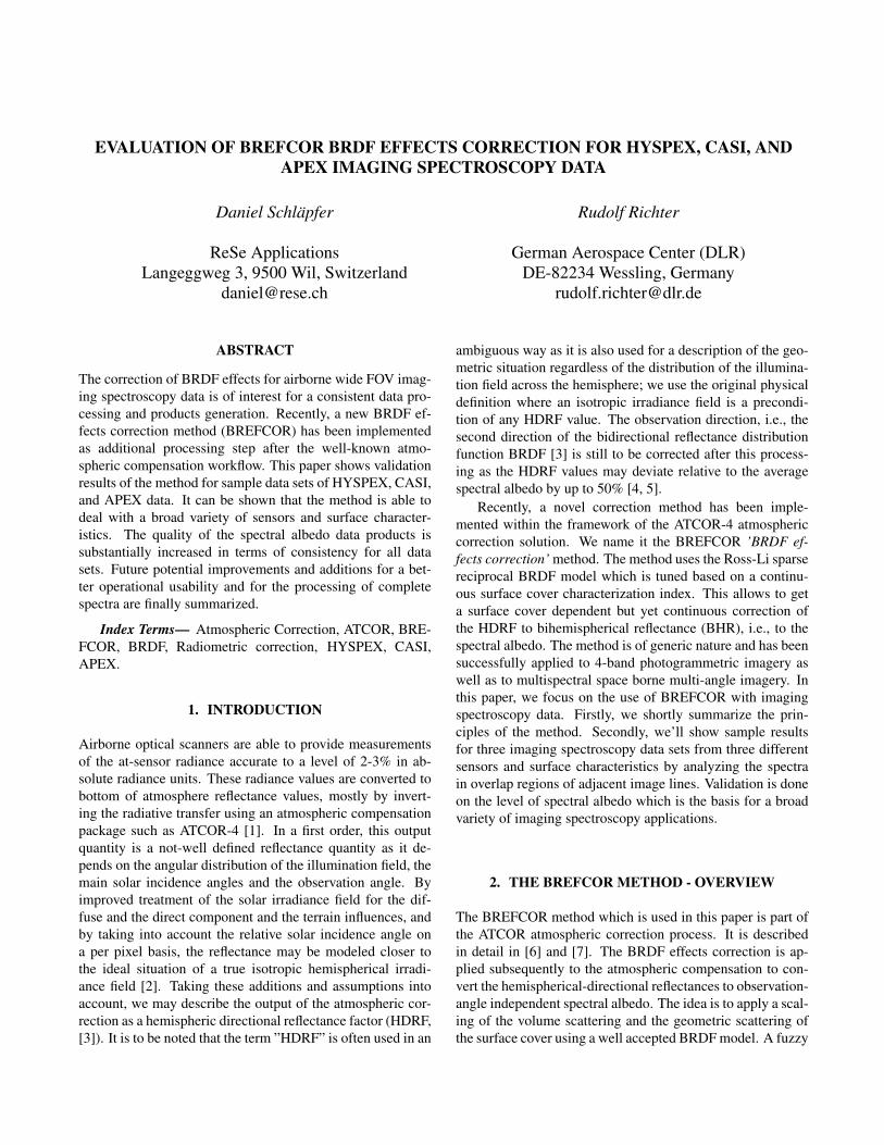
zenith and 113◦ azimuth angle. The Hyspex imaging spec-troscopy system scans the surface with a total FOV of 34◦ in160 contiguous bands for the VNIR spectral range from 410to 990 nm. The BRDF model is calibrated for each of the 160spectral bands individually using 5 steps with calibration lim-its for dense summer vegetation. One of the scenes containedsome clouds and had therefore to be excluded from the modelcalibration step. A result of this correction is shown in Figure1. BRDF effects are well removed for both the grassland andforested areas.
A collection of spectra which illustrate the effect of theBRDF correction is given in Figure 2. The figures show twospectra averages from a 10x10 pixel window of the sametarget viewn from two different observation angles in theoverlapping area of the mosaicked images (see red dots inFigure 2). The BRDF effects are strongly reduced for the
Fig. 1. BRDF correction on Hyspex: left: ATCOR corrected,middle: BREFCOR corrected, right: anisotropy factor. Bandcombination: R:803nm, G:546nm, and B:426nm.
Fig. 2. Spectra of three surface types at edge of image beforeand after BREFCOR correction.
vegetation cover across the full spectral range, reducing theaverage difference in reflectance from 2.5% to below 1%.The concrete sample is hardly affected by the correction as itit shows only small BRDF anisotropy.
4. EVALUATION ON CASI IMAGERY
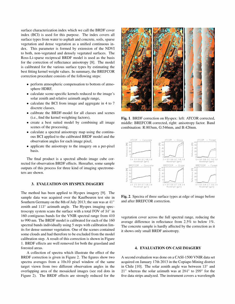
A second evaluation was done on a CASI-1500 VNIR data setacquired on January 17th 2013 in the Copiapo Mining districtin Chile [10]. The solar zenith angle was between 13◦ and21◦ whereas the solar azimuth was at 284◦ to 299◦ for thefive data strips analyzed. The instrument covers a wavelength
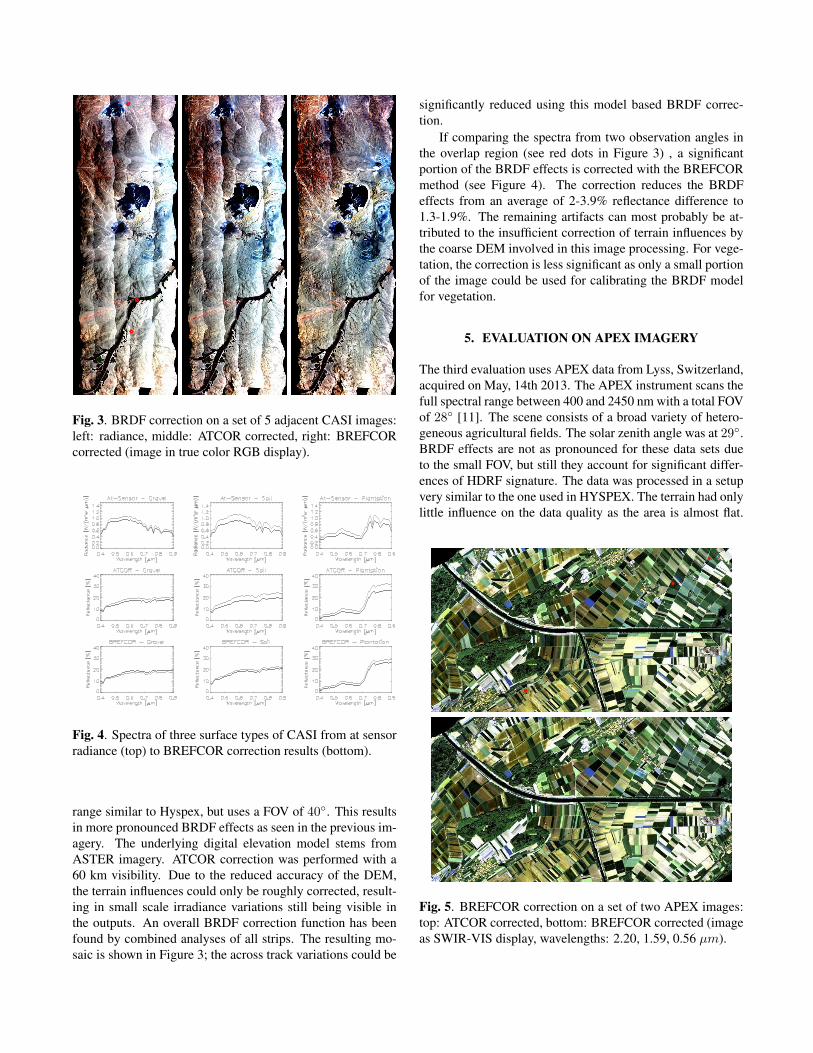
Fig. 3. BRDF correction on a set of 5 adjacent CASI images:left: radiance, middle: ATCOR corrected, right: BREFCORcorrected (image in true color RGB display).
Fig. 4. Spectra of three surface types of CASI from at sensorradiance (top) to BREFCOR correction results (bottom).
range similar to Hyspex, but uses a FOV of 40◦. This resultsin more pronounced BRDF effects as seen in the previous im-agery. The underlying digital elevation model stems fromASTER imagery. ATCOR correction was performed with a60 km visibility. Due to the reduced accuracy of the DEM,the terrain influences could only be roughly corrected, result-ing in small scale irradiance variations still being visible inthe outputs. An overall BRDF correction function has beenfound by combined analyses of all strips. The resulting mo-saic is shown in Figure 3; the across track variations could be
significantly reduced using this model based BRDF correc-tion.
If comparing the spectra from two observation angles inthe overlap region (see red dots in Figure 3) , a significantportion of the BRDF effects is corrected with the BREFCORmethod (see Figure 4). The correction reduces the BRDFeffects from an average of 2-3.9% reflectance difference to1.3-1.9%. The remaining artifacts can most probably be at-tributed to the insufficient correction of terrain influences bythe coarse DEM involved in this image processing. For vege-tation, the correction is less significant as only a small portionof the image could be used for calibrating the BRDF modelfor vegetation.
5. EVALUATION ON APEX IMAGERY
The third evaluation uses APEX data from Lyss, Switzerland,acquired on May, 14th 2013. The APEX instrument scans thefull spectral range between 400 and 2450 nm with a total FOVof 28◦ [11]. The scene consists of a broad variety of hetero-geneous agricultural fields. The solar zenith angle was at 29◦.BRDF effects are not as pronounced for these data sets dueto the small FOV, but still they account for significant differ-ences of HDRF signature. The data was processed in a setupvery similar to the one used in HYSPEX. The terrain had onlylittle influence on the data quality as the area is almost flat.
Fig. 5. BREFCOR correction on a set of two APEX images:top: ATCOR corrected, bottom: BREFCOR corrected (imageas SWIR-VIS display, wavelengths: 2.20, 1.59, 0.56 µm).
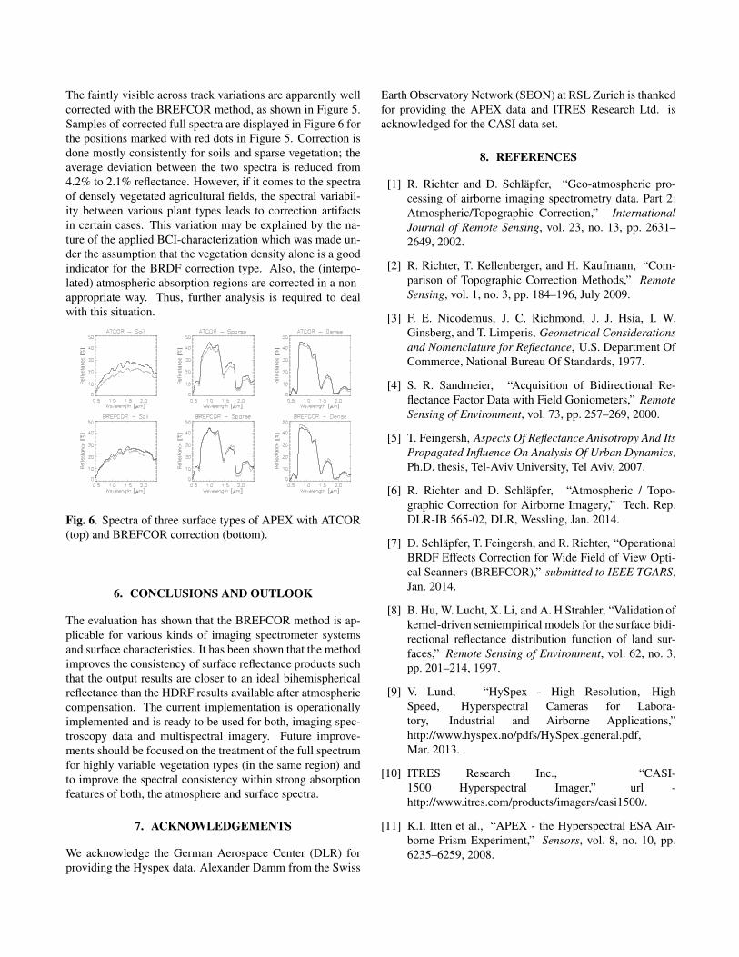
The faintly visible across track variations are apparently wellcorrected with the BREFCOR method, as shown in Figure 5.Samples of corrected full spectra are displayed in Figure 6 forthe positions marked with red dots in Figure 5. Correction isdone mostly consistently for soils and sparse vegetation; theaverage deviation between the two spectra is reduced from4.2% to 2.1% reflectance. However, if it comes to the spectraof densely vegetated agricultural fields, the spectral variabil-ity between various plant types leads to correction artifactsin certain cases. This variation may be explained by the na-ture of the applied BCI-characterization which was made un-der the assumption that the vegetation density alone is a goodindicator for the BRDF correction type. Also, the (interpo-lated) atmospheric absorption regions are corrected in a non-appropriate way. Thus, further analysis is required to dealwith this situation.
Fig. 6. Spectra of three surface types of APEX with ATCOR(top) and BREFCOR correction (bottom).
6. CONCLUSIONS AND OUTLOOK
The evaluation has shown that the BREFCOR method is ap-plicable for various kinds of imaging spectrometer systemsand surface characteristics. It has been shown that the methodimproves the consistency of surface reflectance products suchthat the output results are closer to an ideal bihemisphericalreflectance than the HDRF results available after atmosphericcompensation. The current implementation is operationallyimplemented and is ready to be used for both, imaging spec-troscopy data and multispectral imagery. Future improve-ments should be focused on the treatment of the full spectrumfor highly variable vegetation types (in the same region) andto improve the spectral consistency within strong absorptionfeatures of both, the atmosphere and surface spectra.
7. ACKNOWLEDGEMENTS
We acknowledge the German Aerospace Center (DLR) forproviding the Hyspex data. Alexander Damm from the Swiss
Earth Observatory Network (SEON) at RSL Zurich is thankedfor providing the APEX data and ITRES Research Ltd. isacknowledged for the CASI data set.
8. REFERENCES
[1] R. Richter and D. Schlapfer, “Geo-atmospheric pro-cessing of airborne imaging spectrometry data. Part 2:Atmospheric/Topographic Correction,” InternationalJournal of Remote Sensing, vol. 23, no. 13, pp. 2631–2649, 2002.
[2] R. Richter, T. Kellenberger, and H. Kaufmann, “Com-parison of Topographic Correction Methods,” RemoteSensing, vol. 1, no. 3, pp. 184–196, July 2009.
[3] F. E. Nicodemus, J. C. Richmond, J. J. Hsia, I. W.Ginsberg, and T. Limperis, Geometrical Considerationsand Nomenclature for Reflectance, U.S. Department OfCommerce, National Bureau Of Standards, 1977.
[4] S. R. Sandmeier, “Acquisition of Bidirectional Re-flectance Factor Data with Field Goniometers,” RemoteSensing of Environment, vol. 73, pp. 257–269, 2000.
[5] T. Feingersh, Aspects Of Reflectance Anisotropy And ItsPropagated Influence On Analysis Of Urban Dynamics,Ph.D. thesis, Tel-Aviv University, Tel Aviv, 2007.
[6] R. Richter and D. Schlapfer, “Atmospheric / Topo-graphic Correction for Airborne Imagery,” Tech. Rep.DLR-IB 565-02, DLR, Wessling, Jan. 2014.
[7] D. Schlapfer, T. Feingersh, and R. Richter, “OperationalBRDF Effects Correction for Wide Field of View Opti-cal Scanners (BREFCOR),” submitted to IEEE TGARS,Jan. 2014.
[8] B. Hu, W. Lucht, X. Li, and A. H Strahler, “Validation ofkernel-driven semiempirical models for the surface bidi-rectional reflectance distribution function of land sur-faces,” Remote Sensing of Environment, vol. 62, no. 3,pp. 201–214, 1997.
[9] V. Lund, “HySpex - High Resolution, HighSpeed, Hyperspectral Cameras for Labora-tory, Industrial and Airborne Applications,”http://www.hyspex.no/pdfs/HySpex general.pdf,Mar. 2013.
[10] ITRES Research Inc., “CASI-1500 Hyperspectral Imager,” url -http://www.itres.com/products/imagers/casi1500/.
[11] K.I. Itten et al., “APEX - the Hyperspectral ESA Air-borne Prism Experiment,” Sensors, vol. 8, no. 10, pp.6235–6259, 2008.