evaluation of load rating procedure for ......evaluation of load rating procedure for metal culverts...
TRANSCRIPT
A R C H I W U M I N S T Y T U T U I N Ż Y N I E R I I L Ą D O W E J
Nr 23 ARCHIVES OF INSTITUTE OF CIVIL ENGINEERING 2017
EVALUATION OF LOAD RATING PROCEDURE FOR METAL CULVERTS UNDER SHALLOW SOIL COVERS1
Kevin WHITE, PE*, Shad SARGAND, PhD**, Teruhisa MASADA, PhD*** *) Water Resoures Group Manager, E.L. Robinson Engineering, Columbus, Ohio, USA
**) Russ Professor, Ohio University, Athens, Ohio, USA ***) Professor, Ohio University, Athens, Ohio, USA
Load rating of corrugated metal (CMP) culverts with very low soil cover is poorly defined by AASHTO Load and Resistance Factor Rating (LRFR) procedures. Because of this the Ohio Department of Transportation (ODOT) developed a load rating proce-dure based on the AASHTO LRFD Design Specifications, National Corrugated Steel Pipe Association Design Data Sheet 19, and the stability method proposed by Galambos. A research study was recently completed in Ohio to evaluate the current load rating method, employed by ODOT, for load-rating corrugated metal culverts installed with soil cover less than the minimum specified by current LRFD specifications. Six corru-gated metal culverts were fully instrumented and subjected to a series of static and dy-namic live load tests. The field test data were analyzed to understand the response of shallow-installation CMP culverts to live loading. The sensor readings were also used to compute the thrust response of the culverts. Then, the current ODOT load-rating proce-dure using the field applied live load was utilized to calculate wall thrust. The field de-termined wall thrusts were then compared to the calculated wall thrusts. It was observed that the current ODOT procedure is very conservative, as the calculated thrust values were much higher than the field values for five of the six test structures.
Key words: Soil-steel bridges, load rating, minimum soil cover
1. INTRODUCTION
The Ohio Department of Transportation (ODOT) has the second largest in-ventory of statutory bridges among all State Departments of Transportation in the U.S. The inventory includes over 3300 corrugated metal structures.
Federal Highway Administration (FHWA) requires all bridges to be load-rated using either the load factor rating method (LFR) or load & resistance factor rating method (LRFR). However, neither FHWA nor AASHTO has a compre-
1 DOI 10.21008/j.1897-4007.2017.23.29

312 Kevin White, Shad Sargand, Teruhisa Masada
hensive procedure for load-rating corrugated metal culverts. It is possible to rate metal culverts for thrust and buckling capacity, and seam strength using known analysis methods. ODOT currently utilizes the procedures outlined in the AASHTO LRFD Bridge Design Specifications (2014) and the National Corru-gated Steel Pipe Association Design Data Sheet 19 for the load rating of corru-gated steel culverts. This method provides reasonable results for structures meet-ing the AASHTO minimum soil cover requirements. However, when soil cover is less than that specified by AASHTO, the methods do not offer guidance on determining appropriate load rating factors.
In 2009, ODOT published a report entitled “Verification of ODOT’s Load Rating Analysis Programs for Metal Pipe and Arch Culverts” (Sezen et al, 2009). The report briefly discussed minimum soil cover and the applicability of a previous method utilized by ODOT to assess a culvert’s load rating factor. The earlier method utilized was a linear reduction in the load rating factor based on the proportion of measured cover to required cover. ODOT recognized that this methodology of determining the load rating factor was conservative.
The result of this methodology was that many existing corrugated metal structures were being load rated less than one solely based on cover. This led to difficulties at the local level where many older in-service structures do not meet current minimum cover requirements. Rerouting of school buses and safety equipment became necessary because of structures being listed with reduced legal loads.
In 2012, ODOT revised its load rating methodology to incorporate a stability method proposed in Guide to Stability Design Criteria for Metal Structures by Galambos (1998). This method considers three buckling modes for arches sub-jected to pure compression loading and provides critical load parameters.
In 2015 Ohio University evaluated the recently-modified ODOT load-rating method for corrugated metal culverts under shallow soil covers. This evaluation was considered important in Ohio because no other study of this nature had been performed before and the legal load restrictions were a considerable hardship to local motorists. It was critical to ensure accurate load ratings for corrugated met-al structures.
2. CURRENT ODOT CORRUGATED METAL LOAD RATING PROCEDURE
The current corrugated metal culvert load rating procedure used by ODOT is based on methods presented in Section 12 of the AASHTO LRFD Bridge De-sign Specifications and the National Corrugated Steel Pipe Association Design Data Sheet 19.
Operating and inventory load ratings are determined using the AASHTO HL-93 single axle, HL-93 tandem axle, and the 4 Ohio legal loads. Design cal-

Evaluation of load rating procedure for metal culverts … 313
culations are made for wall buckling stress, thrust capacity of the wall, wall thrust due to soil cover, and wall thrust due to live load including dynamic load allowance. The wall thrust capacity is based on the lowest of the wall yield strength, wall buckling strength, and seam strength. Next, operating and invento-ry load rating factors are computed based on the wall thrust capacity and load rating factors are computed for the minimum cover requirement. For buried cul-verts, the inventory and operating load rating equations are the same. The only difference between the two is the applied live load gamma factor ( ). It is 1.75 for the inventory rating factor equation and 1.35 for the operating rating factor equation. The wall strength rating factor is then calculated using:
where φc = condition factor; φs = system factor; Tcap = wall thrust capacity; γEV = load factor for vertical earth pressure; ηR = load modifier for redundan-cy; TE = wall thrust due to earth load; γLL = load factor for live load; and T(L+IM) = wall thrust due to live load and dynamic allowance.
The minimum cover rating factors are then determined using provisions based on the stability method of Galambos. The minimum cover rating factor is calculated using:
where Hmin = minimum cover over structure; hmod = modified minimum cover using Galambos results; and
2.36 0.528 1.0
where S = structure span.
Critical load parameters for elastic circular arches in pure compression, as formulated by Galambos, are listed in Table 1. The critical load parameters are dependent upon the condition of the buckled structure. The three conditions are fixed arch, two-hinged arch, or three-hinged arch. The fixed arch has each foot of the arch fixed. The two-hinged arch has each foot of the arch pinned. And, the three-hinged arch includes a third pin-joint added to the crown of the two-hinged arch.
The overall rating factor is then taken as the lessor of the wall thrust capacity rating factor and the minimum soil cover rating factor.
314 Kevin White, Shad Sargand, Teruhisa Masada
Table 1. Critical Load Parameter for Circular Arches in Pure Compression (Galambos (1998)).
Symbols: q = critical intensity of distributed load; S = span; H = critical horizontal reaction at supports; E = modulus of elasticity; and I = moment of inertia.
3. RESEARCH PROGRAM
To perform a verification of the current method used by ODOT, it was nec-essary to measure the structural responses of several shallow-cover metal cul-verts under in-service conditions during controlled field live-load tests.
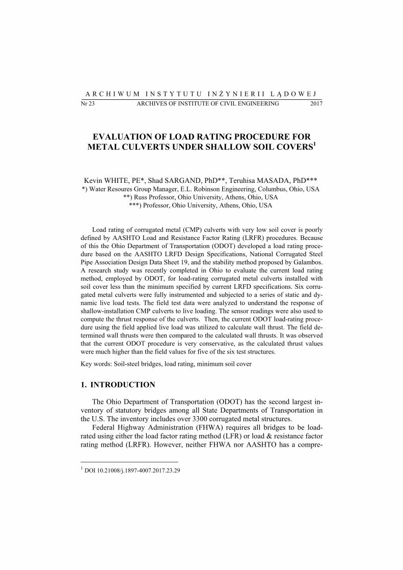
Six shallow-cover corrugated metal culverts were selected for the field test-ing program. One of the structures is shown in Figure 1. Table 2 provides infor-mation on all of the structures tested. Provided information includes the year built, cross-sectional shape, skew angle, soil cover, rise, clear span, and width. Skew angle is the angle between the centerline of the culvert and a perpendicular extension of the roadway centerline. It is also the angle between the corrugations in the culvert and the direction of traffic. If this angle is 0°, the culvert runs per-pendicular to the traffic direction.
Figure 1. WAS-T32-6.25 Arch Culvert (Sargand et. al. (2105))

Evaluation of load rating procedure for metal culverts … 315
Instrumentation Prior to the field live-load tests, each culvert was instrumented with strain
gages under the wheel path located adjacent to either the culvert inlet or outlet end where the soil cover was minimum. Weldable electric resistance strain gages were welded to the surfaces of the aged galvanized steel plates. The strain gages were installed at multiple locations around the circumference at both the crest and valley positions so that axial thrust force and bending moments could be computed from each set of strain gage readings. Furthermore, gauges were placed in pairs and aligned parallel and perpendicular to the corrugation. Sensors were placed under the wheel path, even if the culvert alignment was skewed, because it was anticipated that the greatest stresses and strains would be directly under the test vehicle.
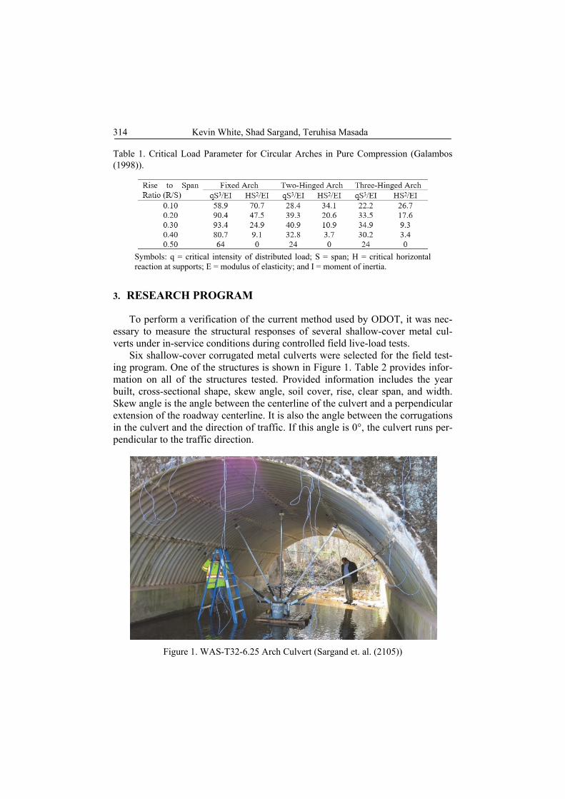
Linear potentiometers were used to record deflections experienced by the culvert during the application of the live load (see Figure 1). In each instrumen-tation section, sensors were installed at key positions such as the crown, shoul-der, and springline (see Figure 2). The exact number and locations of the sensors varied slightly based on the actual in-service conditions of each structure.
4. LIVE LOAD TESTS
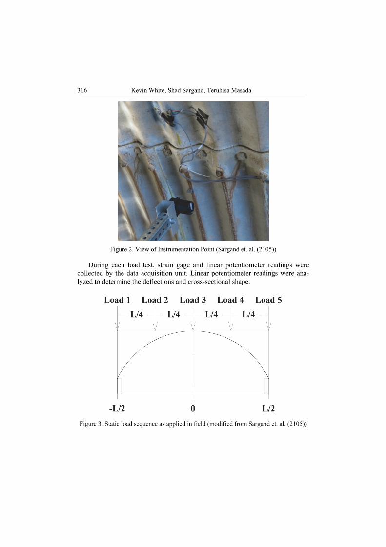
Once instrumentation was complete, the culvert was subjected to static and dynamic loads. Data from the installed sensors were collected using a mobile data acquisition unit. Controlled loads at maximum legal limits were applied to the culvert using a tandem truck. In the static load testing the center of the rear tandem axle of a weighed dump truck was positioned at five different positions over the culvert’s two edges, shoulders, and crown as shown in Figure 3. Figure 4 shows a dump truck’s tandem axles placed above one edge of an arch-shaped culvert. During each dynamic load testing, the same truck was driven over the culvert at speeds of 8, 16, 24, 32, and 40 km/h (5, 10, 15, 20, and 25 mph).
Table 2. Basic Information on Metal Culverts Selected (Sargand et. al. (2105))
316 Kevin White, Shad Sargand, Teruhisa Masada
Figure 2. View of Instrumentation Point (Sargand et. al. (2105))
During each load test, strain gage and linear potentiometer readings were collected by the data acquisition unit. Linear potentiometer readings were ana-lyzed to determine the deflections and cross-sectional shape.
Figure 3. Static load sequence as applied in field (modified from Sargand et. al. (2105))

Evaluation of load rating procedure for metal culverts … 317
Figure 4. Dump Truck Rear Tandem Axle Positioned Above Culvert, Sargand
et. al. (2105)
Potentiometer and Strain Gage Data Analysis Strain gage readings were processed to compute stresses, strains, thrust
force, and bending moment. Normal stresses σA and σB were computed at the sensor locations of the trough and crest of the corrugation (see Figure 5). From these, the stress at the top of the crest, σ′B, is computed to find the extreme strains at the top and bottom of the metal culvert.
Figure 5. Corrugated Plate with Dimensions and Stresses Shown, modified from Sargand et. al. (2105)
5. TEST RESULTS
The narrative provided herein is for the WAS-T32-6.25 culvert. Readers in-terested in viewing test results from the remaining five structures are encouraged to obtain the report by Sargand et al. (2015).
The WAS-T32-6.25 culvert is a single cell, constant radius arch on concrete footings. The structure span is 5.59-m (220-in.). The structure has full-height

318 Kevin White, Shad Sargand, Teruhisa Masada
concrete headwalls. Load testing for the culvert was conducted on Nov. 13, 2013. The rear axle of the truck weighed 177 kN (39.7 kip).
Static load testing resulted in the largest longitudinal strain of –65 με (micro-strain) at the left shoulder and largest crown vertical deflection of –0.81 mm (–0.032 in.) occurring when the load was located at the structure crown (Position 3). The largest transverse strain response of –48 με occurred when the load was located at the right shoulder (Position 2). During the dynamic load testing, the larg-est strains of –74 με longitudinal and –38 με transverse occurred at the left shoul-der. The maximum vertical deflection measured was –0.87 mm ( –0.0344 in.). All of these maximal results resulted from the slowest speed of 8 km/h (5 mph).
Utilizing the the strain gage readings, the largest thrust, located above the right springline was calculated as –73 kN/m (–5.00 kip/ft) when the rear was axle positioned above the left shoulder. The largest moment, located at the crown, was calculated as –0.516 kN-m/m (–116 lb-ft/ft) when the rear axle was positioned above the crown.
Figure 6 through Figure 11present the strains and deflections recorded dur-ing the static and dynamic live load tests.
Figure 6. Longitudinal Strain, Static Position 3 (Sargand et. al. (2015))
Figure 7. Transverse Strain, Static Position 2(Sargand et. al. (2015))
‐70
‐50
‐30
‐10
10
‐100 ‐50 0 50 100
Longitudinal Strain (με)
X‐Coordinate (in)
Peak (A)
Valley (B)
‐60
‐40
‐20
0
20
‐100 ‐50 0 50 100Tran
sverse Strain (με)
X‐Coordinate (in)
Valley (B)
Peak (A)

Evaluation of load rating procedure for metal culverts … 319
Figure 8. Deflection, Static Position 3(modified from Sargand et. al. (2015))
Figure 9. Longitudinal Strain at Left Shoulder, Speed 5 mph(Sargand et. al. (2015))
Figure 10. Transverse Strain at Left Shoulder, Speed 5 mph(modified from Sargand
et. al. (2015))
‐0,040
‐0,030
‐0,020
‐0,010
0,000
0,010
0,020
‐100 ‐50 0 50 100
Deflection (in)
(1 in. = 25.4mm)
X‐Coordinate (in)
‐80
‐60
‐40
‐20
0
20
40
25 30 35 40 45 50 55
Longitudinal Strain (με)
Time (sec)
‐50‐40‐30‐20‐100
1020
25 30 35 40 45 50 55Tran
sverse Strain (με)
Time (sec)

320 Kevin White, Shad Sargand, Teruhisa Masada
Figure 11. Crown Deflection Recorded, Speed 5 mph(modified from Sargand et. al. (2015))
6. ASSESSMENT OF CURRENT ODOT LOAD RATING METHOD
Input data prepared for the six metal culverts are summarized in Table 3. Table 4 lists both the operating load rating factors and the minimum required soil cover computed by three methods (Galambos fixed arch, Galambos 3-hinge arch, and AASHTO LRFD). The fixed arch method provides values that are closer to the values obtained during the field tests. Table 5 compares the thrusts computed from the ODOT load rating methodology and those calculated from the strain gage readings taken during field testing. With the exception of the triple-barrel culvert site (KNO-T123-0.20), the thrusts computed according to the AASHTO LRFD method are significantly larger than those computed from the measured strain gage readings.
Table 3. Load Rating Input Parameters (Sargand et. al. (2015))
1 ft = 0.305 m, 1 ft2 = 0.0929 m2, 1 in2/ft = 0.0021 m2/m, 1 lb = 4.448 N, 1 lb/ft = 14.6 kN/m, 1 pcf = 156.8 kN/m3, 1 psf = 48 N/m2, 1 psi = 6.894 kN/m2. Imperial units are provided because AASHTO standards do not provide metric equivalent equations.
‐0,040
‐0,030
‐0,020
‐0,010
0,000
0,010
25 30 35 40 45 50 55 60
Deflection (in)
(1 in. = 25.4mm)
Time (sec)

Evaluation of load rating procedure for metal culverts … 321
Table 4. Load Rating Factor (LRF) and Min. Soil Cover Values Specified by Three Methods (Sargand et. al. (2015))
** Load distribution through the fill is never sufficiently great to result in the maximum distrib-
uted load (qmax) being less than the critical intensity of distributed load (qcr) ** Actual cover is less than the minimum cover specified for this method Unit Conversion:
1 ft = 0.305 m. Imperial are provided because AASHTO standards do not provide metric equivalent equations.
Table 5. Comparison Between Calculated and Measured Maximum Thrust Force (Sargand et. al. (2015))
This result should be expected because AASHTO methodology is based on compression ring theory. Live loads, regardless of the height of cover, are con-verted to an equivalent pressure. This pressure is applied as a uniform pressure across the entire width of the structure. This results in a calculated thrust re-sponse significantly greater than the actual wall thrust. This inherent weakness in the application of live loads to shallow buried compression rings is minimized with increasing height of covers.
7. SUMMARY AND CONCLUSIONS
This paper describes a limited portion of a comprehensive study conducted in 2015 in Ohio to evaluate the recently modified ODOT’s load-rating method for corrugated metal culverts under shallow soil covers. In the study, six metal culverts with very shallow cover, were instrumented with sensors and subjected to a series of static and dynamic live load tests. The field test data were analyzed

322 Kevin White, Shad Sargand, Teruhisa Masada
to gain insight into the response of shallow-buried metal structures to live load-ing and to assess current ODOT load rating procedure where soil cover is less that that required by AASHTO specifications.
All of the field tested culverts performed very well under live loads that were close to the Ohio legal limit. This is despite the fact that they were under ex-tremely shallow soil covers. The maximum culvert responses (thrust and deflec-tion) were observed at the slowest vehicle speed (8 km/h or 5 mph) and general-ly agreed with those generated by the static load using the same vehicle. This trend was observed for each of the five single-cell culverts. However, the trend did not hold for the multiple culvert configuration.
For all cases the calculated thrust using AASHTO methodologies were greater than the measured thrusts obtained during field experiments.
Based on the limited field data obtained during this investigation, the load rating methodology utilized by ODOT appears to be conservative.
Culverts are very different in some important respects to bridges, and their response to load is more complicated. Bridge loads are entirely supported by the constituent bridge members. However, metal culverts rely on the surrounding soil for a significant portion of their load carrying capability.
There is generally a lack of knowledge about the material properties of the backfill surrounding in-situ culvert installations. Load ratings for shallow cover culverts need to be augmented with proper inspections conducted on a regular basis. These inspections should include an assessment of the surrounding soil. The importance of the surrounding soil cannot be underestimated. A culvert may be rated for heavy loads, but if the backfill weakens, by erosion or saturation, then the culvert should be inspected and the load rating may then need to be significantly reduced to maintain safe operation.
LITERATURE
1. AASHTO (2011). Manual for Bridge Evaluation, 2nd Edition. American Association of State Highway and Transportation Officials, Washington DC, 2011.
2. AASHTO (2014). LRFD Bridge Design Specifications, 7th Edition. American Associ-ation of State Highway and Transportation Officials, Washington DC, 2014.
3. Federal Highway Administration (FHWA) (1986). Culvert Inspection Manual, Sup-plement to the Bridge Inspector’s Training Manual, Report No. FHWA-IP-86-2, July 1986, 200 pages. Available online at http://isddc.dot.gov/OLPFiles/FHWA/ 006625.pdf, accessed March 8, 2013.
4. Galambos, T. V. (1998). Guide to Stability Design Criteria for Metal Structures, 5th edition, John Wiley. (6th edition, 2010, edited by Ronald D. Zieman).
5. Hardert, M., Noll, J., and Dennis, J. (2012). “Field Inspection, Evaluation and Load Rating of Installed Corrugated Metal Culvert Structures”, Presentation at Ohio Trans-portation Engineering Conference, Oct. 31, 2012. Slides available online at http://www.dot.state.oh.us/ engineering/OTEC/2012%20Presentations/58A-NollEtAl. pdf, accessed March 8, 2013.

Evaluation of load rating procedure for metal culverts … 323
6. Korusiewicz, L. and Kunecki, B. (2011). “Behaviour of the steel box-type culvert during backfilling”, Archives of Civil and Mechanical Engineering, 11(3), 637-650.
7. National Corrugated Steel Pipe Association (2013). NCSPA Design Data Sheet 19 “Load Rating and Structural Evaluation of In-Service, Corrugated Steel Structures,” Revised February 2013, 12 pages. Available online at http://www.ncspa.org/ images/stories/technical/ dds19revfeb2013.pdf, accessed March 8, 2013.
8. Sargand, S. M., White, K., Khoury, I., Hussein, H., Mutashar, R., Jordan, B., and Russ, A. (2015). Task 4 – Validation of ODOT Shallow Cover Rating Factor Method-ology for Metal Pipe & Arch Culverts, Structures Research Service Report to Ohio Department of Transportation, February 2015, Civil Engineering Dept., Ohio Univer-sity, Athens, OH. 150 pp.
9. Sezen, H., Fox, P. P., and Yeau, K. Y. (2009). Verification of ODOT’s Load Rating Analysis Programs for Metal Pipe and Arch Culverts, SJN 134225, Report No. FHWA/OH-2009/6 for the Ohio Department of Transportation, August 2009. Availa-ble online at http://www.dot.state.oh.us/Divisions/Planning/SPR/Research/ reportsandplans/Reports/2009/Structures/134225-FR.pdf, accessed March 8, 2013.