evaluation of micromachining processes using … · such as granite and basalt, glass, concrete,...
TRANSCRIPT

Journal of Machine Engineering, Vol.15, No. 4, 2015
Received: 29 July 2015 / Accepted: 22 October 2015 / Published online: 10 November 2015
microfinishing micro-chips,
discontinuity
Wojciech KACALAK1
Katarzyna TANDECKA1*
Lukasz RYPINA1
EVALUATION OF MICROMACHINING PROCESSES USING DATA IN THE
FORMAT AND GEOMETRIC CHARACTERISTICS OF MICRO-CHIPS
Studies on micro-chips formed in the process of micromachining, including grinding and microfinishing using
abrasive films, were conducted. Geometric characteristics of the micro-chips were analyzed and the presence
of very long chips compared to their width was observed. One also reported the presence of very high
temperatures in the treatment zone despite the applied cooling, which resulted in the formation of spherical
chips. The occurrence of two characteristic spherical chip structures was observed followed by evaluation
of their chemical composition. Based on the tabular structure of band chips, characteristic micro-discontinuities
in the microcutting process were determined.
1. INTRODUCTION
Abrasive micromachining processes are commonly used in the production of precise
elements of machines and systems in industries such as construction machinery,
shipbuilding, automotive, aviation, aerospace, military, and also in construction, mining,
medicine and many other industries [6].
Machined materials constitute a very diverse collection - these are steels and alloys,
including light metals and their alloys, ceramics, cemented carbides, composite materials
such as granite and basalt, glass, concrete, wood, plastics, and precious stone crystals such
as diamond, ruby, sapphire, emerald and also silicon monocrystals as well as many other
materials characterized by increased hardness and resistance to abrasion.
Among micromachining processes, one can distinguish grinding with small depths and
high speeds, as well as the processes of microfinishing with abrasive films.
In microfinishing process with abrasive films which is different than grinding,
compliant fixing of abrasive grains in the film pressed against the object with flexible roll
causes the reduction of high of grains’ vertices in the treatment zone which increases the
__________________
1 Koszalin University of Technology, Faculty of Mechanical Engineering, Department of Precision Engineering,
Koszalin, Poland * E-mail: [email protected]
60 Wojciech KACALAK, Katarzyna TANDECKA, Lukasz RYPINA
uniformity of mechanical and thermal loads [8,],[9],[10],[11],[21],[22]. The speed of the
film displacement is several times reduced compared to the speed of the object, which in
turn is much less than the speed of grinding, and therefore results in the formation of very
long machining marks [12],[13].
Microfinishing process consists of several steps in which one uses tools with
successively finer grains [20]. Machining is performed by scrolling the abrasive film from
the feed gear into the winding gear. Between these gears, there is a gear pressing abrasive
film to the workpiece [18],[19],[15]. The hardness of the pressure gear and its pressure force
affect the surface area of the contact zone of the tool with the workpiece [16]. Significant
feature of the process is that the speed of the abrasive film shifting is from 500 to 3000
times lesser than the shifting speed of the workpiece. Consequently, abrasive grains are
found in the treatment zone for a long time and form machining marks of considerable
length. Machining products formed in the smooth zone must fit in the spaces between
grains.
2. GEOMETRIC FEATURES OF MICRO-CHIPS
To study the characteristics of the micro-chips in the process of micromachining,
products formed during microfinishing with abrasive films and grinding using a small
machining depth, were used.
The process of microfinishing with abrasive films was carried out using IMFF-type
abrasive films, that is films for finishing, wherein the abrasive grains made
of electrocorundum are deposited on the surface of the polyester carrier using electrostatic
method, which results in such orientation of abrasive grains to maximize their machined
ability. In the machining process, one used films with a nominal particle size of 15 µm,
the workpiece was 40 H steel shaft thermally improved to a hardness of 60 HRC.
The machining was performed for 160 seconds with a speed of the object estimated at
35 m/min with pressure gear used with elastomer hardness of 80oSh A. The speed of the
film movement was 160 mm/min, and the pressure force was 60 N.
After finishing process, one collected micro-chips samples, which are products
of micro-finishing from the abrasive film surface. In order to determine the geometric
characteristics of micro-chips, data acquisition was performed using a Phenom table-top
scanning electron microscope, which allowed to obtain magnification to 100.000×.
In order to compare the products of micro-machining, one conducted the process
of grinding with small depths. One used 1-250×25×76.2-99A100K7VTE10-35 grinding
wheel with ceramic binder grains’ size of precious electrocorundum sized 125–150 µm.
The following parameters of the process were used: circumferential speed of grinding wheel
35 m/s, conditioning traverse 0.1–0.15 mm, longitudinal feed 25 m/min. Samples were
microfinished using of X153CrMoV12 (NC11LV) material, made of ledeburitic chromium
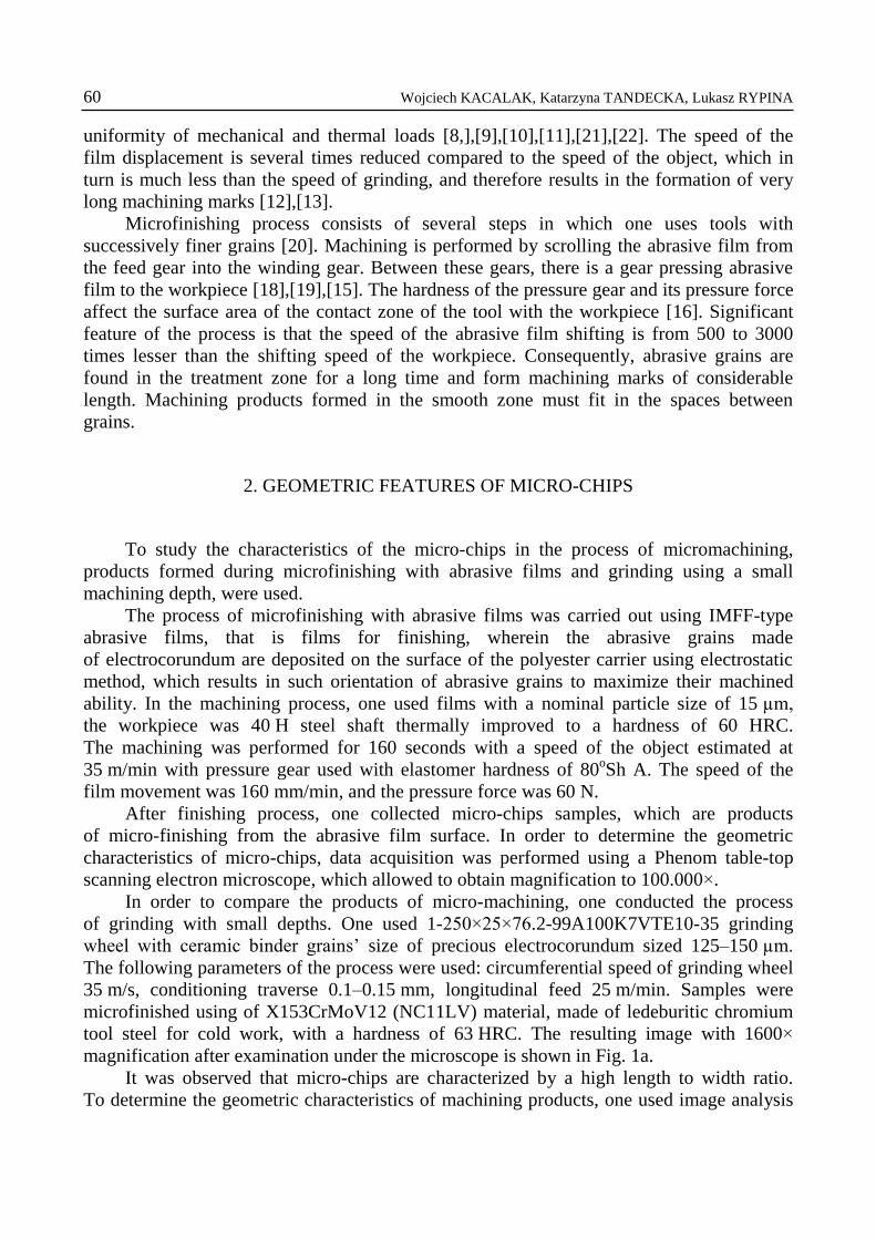
tool steel for cold work, with a hardness of 63 HRC. The resulting image with 1600×
magnification after examination under the microscope is shown in Fig. 1a.
It was observed that micro-chips are characterized by a high length to width ratio.
To determine the geometric characteristics of machining products, one used image analysis
Evaluation of Micromachining Processes Using Data in the Format and Geometric Characteristics… 61
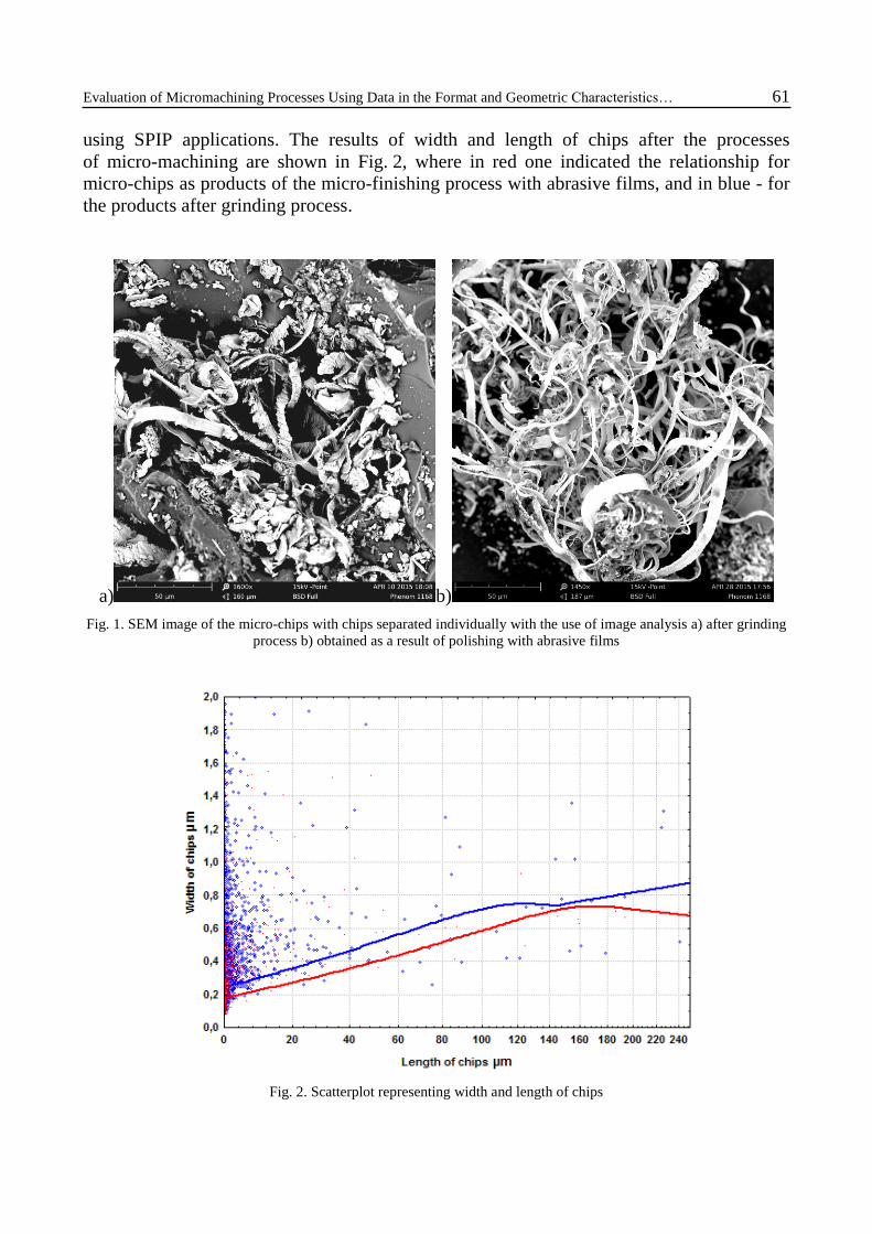
using SPIP applications. The results of width and length of chips after the processes
of micro-machining are shown in Fig. 2, where in red one indicated the relationship for
micro-chips as products of the micro-finishing process with abrasive films, and in blue - for
the products after grinding process.
a) b)
Fig. 1. SEM image of the micro-chips with chips separated individually with the use of image analysis a) after grinding
process b) obtained as a result of polishing with abrasive films
Fig. 2. Scatterplot representing width and length of chips

62 Wojciech KACALAK, Katarzyna TANDECKA, Lukasz RYPINA
The occurrence of long and narrow chips in each of the micromachining processes
tested was reported. Smaller width in relation to chip’s length occurs when micro-polishing
with abrasive films is used, which has a direct relationship with nominal size of grains and
specificity of machining and results in a long surface contact of a single grain with the
workpiece [4],[5].
3. DISCONTINUITY OF THE PROCESS OF MATERIAL DISPLACEMENT IN
THE CONTACT ZONE OF GRAINS AND SUBJECT LAYER SHAPED
In the conducted microscopic studies of micro-chips, one observed large variation in
shapes and forms of machining of products, as well as their characteristic stepped structure.
To better understand the mechanism of formation of such different forms of micro-chips
[1],[2],[3],[17] one performed modeling process of microcutting of a single grain in 3D, in
an environment using finite element method.
The modeling was done using Ansys system for abrasive grains presented in Fig. 3 and
for the workpiece – 4340 stain and microcutting speed vs=25 m/s. To obtain more
information about the particular process for different grains’ depth, sample surface was
inclined so that the depth of microcutting differed from 0 µm to 200 µm.
The objective of this study was to determine the effect of geometric characteristics
of abrasive grain corner on lateral material flow, chip formation and separation of the
material. It should be noted that in micro-machining, lateral (with respect to microcutting
track) material flows are dominated, while typically, one examines only the geometric
conditions of chips’ formation in a perpendicular cross-section to the surface of the object
and parallel to the direction of blade movement [7],[14]
a)

Evaluation of Micromachining Processes Using Data in the Format and Geometric Characteristics… 63
b)
c)
Fig. 3. Discontinuity images in the process of chip formation in micro-cutting with s single grain (a, b, c)
In the modeling study, one used real geometry of grain made of precious
electrocorundum digitized with the use of highly precise GOM's ATOS Triple Scan optical
scanner. It can be observed, that as a result of the action of a single abrasive grains towards
the workpiece, as a result of the uplift of the material particles of the object, numerous chips
of different widths and shapes (Fig. 3) are formed, which has a direct relationship with the
existence of many rubbing planes of abrasive grain of a complex shape.

64 Wojciech KACALAK, Katarzyna TANDECKA, Lukasz RYPINA
4. EVALUATION OF THE FREQUENCY OF MICRO-CHIP ELEMENT FORMATION
OF TABULAR STRUCTURE
Micro-discontinuity of machining processes appears in the form of stepped shaped
construction of micro-chips (Fig. 4). The study of tiles’ thickness gp which form chips
taking into account swelling coefficient wsp allowed determining the frequency of micro-
discontinuity in the micromachining processes tested, that is in grinding and microfinishing
with abrasive films.
a) b)
Fig. 4. The stepped construction of micro-chips as products of grinding process (a), microfinishing with
abrasive films (b)
Fig. 5. Stepped construction of micro-chips products of grinding process: (a) microfinishing with abrasive films,
(b) with determined thicknesses of tiles gp

Evaluation of Micromachining Processes Using Data in the Format and Geometric Characteristics… 65
The frequency of material separation in the process of micro-machining was
determined according to the following formula (1):
spp
p
wwg
vf
(1)
where:
fw – frequency of micro-discontinuity in the process of material separation determined by
the evaluation of chip structure,
vp – speed of the workpiece in the process of microfinishing with abrasive films or
circumferential speed of grinding wheel in grinding process,
gp – thickness of the chip tile of stepped structure (Fig. 5),
wsp – swelling coefficient (resulting also from the displacement of tiles forming the stepped
structure of the chip) which is estimated to be about 10.
The following results were obtained:
fw (microfinishing) = 0,45 MHz fw (grinding) = 25 MHz
Analyzing the results obtained, it can be observed that much higher frequencies
of material separation are reported in the process of grinding, which is directly influenced
by the speed of machining. In both processes, similar thickness of micro-chips’ tiles are
observed, which should be considered depending on the characteristics of the workpiece.
5. CHARACTERISTIC FEATURES OF MICRO-CHIPS OF SPHERICAL SHAPE
In the processes of micro-machining, one also observed chips which form was closely
related to spherical shape. In the microfinishing process, one used coolant injected as a flow
into the machining zone, however despite the cooling used, temperatures in the machining
a) b)
Fig. 6. Chips of spherical form generated in the process of grinding

66 Wojciech KACALAK, Katarzyna TANDECKA, Lukasz RYPINA
a) b)
Fig. 7. Chips of spherical form generated in the process of polishing with abrasive films
zone were high and caused melting and rapid solidification of the small fragments
of material, which results in formation of spherical chips with a very complex structure on
the surface of the spheres. Different sizes of microspheres whose diameter ranged from
a few to tens of micrometers, were observed.
After evaluation of chemical composition of spherical chips (Fig. 8, Table 1), one
observed strong oxidation of the material in comparison to classic forms of chips. At the
same time, one observed two types of chips’ surface structures as a result of microfinishing
with abrasive films shown in Fig. 7.
Fig. 8. Plot of scattered X-radiation energy from the micro-area of the chip tested in the form of Microsphere

Evaluation of Micromachining Processes Using Data in the Format and Geometric Characteristics… 67
Table 1. The volume content of individual elements in spherical micro-chip
Element symbol Element name Volume content % Error of the result
O Oxygen 72.2 0.0
Fe Iron 25.8 0.0
C Carbon 2.0 0.6
6. SUMMARY
The phenomenon of micro-discontinuities of chips’ formation and its frequency may
be determined based on their characteristic, stepped construction. It was found that
thickness of steeped shaped plates forming the chip is approximately 150 nm, which allows
to estimate the frequency of slips (displacement of chip elements) at fw=0.4–25 MHz
depending on the kinematic characteristics of the process.
The adopted methodology allows determining the micro-discontinuities and statistical
parameters of chips and their construction characteristics. The results of the study allow
making recommendations regarding increased efficiency of extremely precise machining,
including the structure of films, characteristics of the pressure rolls and characteristics of the
surface topography of grinding wheels.
ACKNOWLEDGMENTS
REFERENCES
[1] CORONADO J.J., SINATORA A., 2011, Effect of abrasive size on wear of metallic materials and its
relationship with microchips morphology and wear micromechanisms: Part1, Wear, 271, 1794-1803.
[2] DAVIES M.A., BURNS T.J., EVANS C.J., 1997 On the dynamics of chip formation in machining hard metals.
CIRP Annals—Manufacturing Technology, 46, 25-30.
[3] HUA J., SHIVPURI R., 2004, Prediction of chip morphology and segmentation during the machining of
titanium alloys, Journal of Materials Processing Technology, 150, 124-133.
[4] JOURANI A., DURSAPT M., HAMDI H., RECH H., ZAHOUANI H., 2005, Effect of the belt grinding on the
surface texture: Modeling of the contact and abrasive wear, Wear, 259/7–12, 1137-1143,
[5] JOURANI A., HAGEGE B., BOUVIER S., BIGERELLE M., ZAHOUANI H., 2013, Influence of abrasive
grain geometry on friction coefficient and wear rate in belt finishing, Tribology International, 59, 30-37.
[6] KACALAK W., BALASZ B., TOMKOWSKI R., LIPINSKI D., KROLIKOWSKI T., SZAFRANIEC F.,
TANDECKA K., RYPINA L., 2014, Scientific problems and development trends of abrasive micromachining,
Mechanik, 8-9, 157-170/724, (in Polish).

68 Wojciech KACALAK, Katarzyna TANDECKA, Lukasz RYPINA
[7] KACALAK W., KROLIKOWSKI T., RYPINA L., 2013, Modeling process difficult-Microcutting materials in
finite element solver LS-DYNA, Mechanik, 8-9, 226-240, (in Polish).
[8] KACALAK W., TANDECKA K., 2012, Analysis of the impact stereometric features and deployment tops of the
abrasive grains of film on the treated surface shape irregularities, Mechanik, 8-9, 115-127, (in Polish).
[9] KACALAK W., TANDECKA K., 2011, Metrological aspects of the evaluation of diamond abrasive films
topography for precise microfinishing, PAK, 57/5, 531-535, (in Polish).
[10] KACALAK W., TANDECKA K., 2011, Methodology for assessing the topography of the abrasive film for the
precise superfinishing, Archiwum technologii maszyn i automatyzacji, 31/4, 87-95, (in Polish).
[11] KACALAK W., TANDECKA K., Evaluation of the potential of technological abrasive diamond films using
information about the topography of the active surface, Pomiary Automatyka Kontrola, 58/06, 540-544, (in
Polish).
[12] KACALAK W., TANDECKA K., LIPINSKI D., MATHIA T.G., 2014, Micro and nano - discontinuities of
chips formations in diamond foils abrasive finishing process , 2nd International Conference on Abrasive
Processes - ICAP, Cambridge UK, 25.
[13] KACALAK W., TANDECKA K., 2014, The effects of the use of discontinuous active surface of microfinishing
films for superfinishing process, MECHANIK, 8-9, 36-40, (in Polish).
[14] KACALAK W., TANDECKA K., SEMPRUCH R., 2013, Modelling research of Microcutting process,
MECHANIK, 8-9, 189-202/702 (in Polish).
[15] KERSTING P., JOLIET R., KANSTEINER M., 2015, Modelling and simulative analysis of the micro-finishing
process, CIRP, Annals - Manufacturing Technology, 64/1, 321-324.
[16] KHEOLLOUKI A., RECH J., ZAHOUANI H., 2007, The effect of abrasive grain's wear and contact conditions
on surface texture in belt finishing, Wear, 263/1-6, 81-87.
[17] LASRI L., NOUARI M., EL MANSORI M., 2009, Modelling of chip separation in machining unidirectional
FRP composites by stiffness degradation concept, Composites Science and Technology, 69/5, 684-692,
[18] MEZGHANI S., EL MANSORI M., 2008. Abrasiveness properties assessment of coated abrasives for precision
belt grinding, Surface and Coatings Technology, 203/5-7, 786-789.
[19] MEZGHANI S., EL MANSORI M., SURA E., 2009, Wear mechanism maps for the belt finishing of steel and
cast iron, Wear, 267/1-4, 86-91.
[20] SERPIN K., MEZGHANI S., EL MANSORI M., 2015, Multiscale assessment of structured coated abrasive
grits in belt finishing process, Wear, 332-333, 780-878.
[21] GRZESIK W., ZAK K., 2013, Comparison of surface textures produced by finish cutting, abrasive and
burnishing operations in terms of their functional properties, Journal of Machine Engineering, 13/2, 46-58.
[22] TAKAHASHI S., TANABE I., FUKUDA N., 2014, Development of polishing technology using heat for mirror-
like surface of aluminum, Journal of Machine Engineering, 14/2, 57-68.