evaluation of pegit duct connection system
TRANSCRIPT

LBNL 43382
ERNEST ORLANDO LAWRENCE BERKELEY NATIONAL LABORATORY
Evaluation of PEGIT Duct Connection System
I.S. Walker, D.E. Brenner, M.H. Sherman and D.J.
Dickerhoff
Environmental Energy Technologies Division August 2003 This work was supported by the US Department of Energy (DOE) Cooperative Research and Development Agreement BG97-352(01) and by the Assistant Secretary for Energy Efficiency and Renewable Energy, Building Technologies Program of the U.S. Department of Energy under contract no. DE-AC03-76SF00098.

Disclaimer
This document was prepared as an account of work sponsored by the United States Government. While this document is believed to contain correct information, neither the United States Government nor any agency thereof, nor The Regents of the University of California, nor any of their employees, makes any warranty, express or implied, or assumes any legal responsibility for the accuracy, completeness, or usefulness of any information, apparatus, product, or process disclosed, or represents that its use would not infringe privately owned rights. Reference herein to any specific commercial product, process, or service by its trade name, trademark, manufacturer, or otherwise, does not necessarily constitute or imply its endorsement, recommendation, or favoring by the United States Government or any agency thereof, or The Regents of the University of California. The views and opinions of authors expressed herein do not necessarily state or reflect those of the United States Government or any agency thereof, or The Regents of the University of California. Ernest Orlando Lawrence Berkeley National Laboratory is an equal opportunity employer.
2

Evaluation of PEGIT duct connection system INTRODUCTION Most air duct system components are assembled in the field and are mechanically fastened by sheet metal screws (for sheet metal-to-sheet metal) or by drawbands (for flex duct-to-sheet metal). Air sealing is separate from this mechanical fastening and is usually achieved using tape or mastic products after mechanical fastening. Field observations have shown that mechanical fastening rarely meets code or manufacturers requirements and that sealing procedures are similarly inconsistent. To address these problems, Proctor Engineering Group (PEG) is developing a system of joining ducts (called PEGIT) that combines the mechanical fastening and sealing into a single self-contained procedure. The PEGIT system uses a shaped flexible seal between specially designed sheet metal duct fittings to both seal and fasten duct sections together. Figure 1 shows the inner duct fitting complete with rubber seal. This seal provides the air seal for the completed fitting and is shaped to allow the inner and outer fittings to slide together, and then to lock the fittings in place. The illustration in Figure 2 shows the approximate cross section of the rubber seal that shows how the seal has a lip that is angled backwards. This angled lip allows the joint to be pushed together by folding flat but then its long axis makes it stiff in the pulling apart direction. This study was undertaken to assist PEG in some of the design aspects of this system and to test the performance of the PEGIT system.
Figure 1. Inner PEGIT duct fitting showing rubber seal This study was carried out in three phases. The initial phase evaluated the performance of a preliminary seal design for the PEGIT system. After thirst first phase, the seal was redesigned and this new seal was evaluated in the second phase of testing. The third phase performed more detailed testing of the second seal design to optimize the production tolerances of the sheet metal fittings. This report summarizes our findings from the first two phases and provides details about the third phase of testing.
Phase 1. A detailed report on Phase 1 can be found in Appendix 1. In Phase 1, the initial PEGIT design was tested for leakage and evaluated for equivalence to mechanical code requirements. The results of this phase showed that the PEGIT system had the ability to produce duct fitting seals that were as good as a conventional taped connection (less than
3

0.5 cfm leakage at 25Pa) and considerably better than an unsealed connection (1.7 cfm leakage at 25 Pa). However, the testing revealed two problems that were both related to the inability of the inner duct’s formed lip to maintain the position of the seal on the inner duct. The first problem was that the seal was not securely held from moving longitudinally by the lip. Combined with the friction between the rubber seal and duct surfaces, this led to the seal being pulled out of the crimped lip in the round sheet metal as it was inserted into the outer duct section. When the seal was incorrectly seated in this way, it resulted in additional connection leakage. The second problem with the seal was that when it was seated improperly the seal it was not held at the correct angle (as shown in Figure 1). This angle is critical because it is a factor in determining the sealing force and the forces required to assemble or dissemble the duct sections.
Seal angle
Seal correctlyseated in fitting
Seal angle
Seal pulled out offitting
Figure 2. Seal deformation: When the seal is pulled out of the fitting due to
deformation during assembly, the angle of the seal leads to reduced pressure on the inside of the outer fitting
4

To test the mechanical security of the connection, adjustable test samples were constructed. A longitudinal section of the sheet metal was removed (about 0.25 inch (6 mm)) for several inches at the end of the sample. The resulting gap allowed us to adjust the circumference of the fitting using a screw adjuster (see Figure 3). This adjustability meant that it was not possible to evaluate the security of a production fitting. However, the basic concept of having a rubber seal snap into a groove in a sheet metal fitting provides a good mechanical connection that is very difficult to pull apart. This means that the design meets the intent of the Uniform Mechanical Code (UMC (1994)1), which states that sheet metal duct connections must be secured using three sheet metal screws “... or an equivalent fastening method.”. Given that the UMC does not give any specifications for the strength of the duct connection, there is no reason to believe that the PEGIT system should not be acceptable.
Figure 3. Screw adjustable PEGIT fitting
Phase 2. In the second phase of testing, the PEGIT design had been changed based on the findings in Phase 1. A new seal shape and a different profile for the sheet metal fittings was developed that would keep the seal in place. An improved leakage test apparatus using high precision orifices was used for the leakage testing. The forces required to assemble and pull apart the fittings were estimated using simple procedures. The remainder of this section summarizes the procedures and results of our Phase 2 leakage tests and our assembly and disassembly force tests. Appendix 2 provides more details about the Phase 2 tests.
Phase 2 Leakage Testing The Phase 2 leakage tests used the apparatus illustrated in Figure 4. The leakage is determined by pressurizing the test sample over a range of pressure differences from
1 Uniform Mechanical Code. 1994. International Conference of Building Officials. Whittier, CA. Paragraph 601.5.1
5

about 10 Pa to 50 Pa and measuring the airflow required to maintain each pressure difference. For comparison purposes, a reference pressure difference of 25 Pa was chosen; this is a common reference pressure used in duct leakage testing. Based on our tests, the leakage flow at 25 Pa pressure difference is 0.26 cfm (0.12 L/s). This is very close to the 0.3 cfm (0.14 L/s) at 25 Pa measured in Phase 1. This is a very low level of leakage: it was about one half the leakage measured for a well-taped connection of a similar configuration.
Sample Connection
Airflow measurement venturi
Airflow from fan
Figure 4. Phase 2 test apparatus for leakage testing.
Phase 2 Assembly and disassembly forces We used two different methods to assess the force required to push the two parts of the connection together.
Assembly Force, Method1: Placing weight on the sample A simple method of loading the connection that allows large cumulative weights, while allowing very small incremental weight changes, is to add water to a bucket placed on top of the sample connection. This method also ensures that the round sheet metal section is loaded evenly around the circumference. However, we found that even with a full bucket of water the connection was not pushed together. The bucket and water exerted a force of 45 lbf (200 N).
Assembly Force, Method 2: Direct loading on a scale In this second test, the sample was placed on a scale and was loaded by having a technician push on the end of the sample (as shown in Figure 5). The assembly force was 145 lbf (645 N). Even at this high loading, it is necessary to wiggle the fitting from side to side to help slide the outer duct section over the rubber ring seal.
6

Figure 5. Assembly force measurement using a scale
Disassembly Force To pull the connection apart, the joined ducts were suspended from a scale to record the applied force. A lever was used to apply the disassembly force by pulling down on the other end of the connection. This allowed us to safely place large loads on the connection. Figure 6 is a photograph of this experimental apparatus. The connection was loaded with up to 110 lbf (490 N), but did not separate. We stopped testing at this load because it is far in excess of any separation force we can reasonably imagine would be applied in a field installation.
7

Scale
Test sample
Figure 6. Disassembly testing using sca
Phase 2 Summary The results of the second phase of testing showed that metal components solved the problems found in Phase 1required disassembly forces were acceptable, but the asseconsidered 20 lbf (90 N) to be a reasonable limit for assemand deflection of plenum and other duct assemblies made This led to the final phase of testing to investigate opdimensions to balance leakage and assembly force requirem
Phase 3 In Phase 3, a combination of fixed-diameter and adjustdiameter outer sheet metal duct sections were used tobetween the inner and outer ducts. The corresponding outer, fixed inner/fixed outer) are discussed in this sectionto optimize the assembly force and air tightness, andproduction tolerances on system performance. To make tcontrollable, one end of the outer duct section was weldmm×230 mm×4.8 mm) steel plate with a 5” (127 mm) dinside diameter of this duct. The size of the plate coincid
Lever arm
le and lever
the redesigned seals and sheet . The resulting air seal and
mbly forces were too high. We bly force based on the strength
from duct board or sheet metal. timizing the sheet metal part ents.
able-diameter inner and fixed- systematically vary the gap results (adjustable inner/fixed . This adjustability allowed us to investigate the effects of he testing more repeatable and ed onto a 9”×9”×0.188” (230 iameter hole aligned with the
es with the leakage test fixture
8
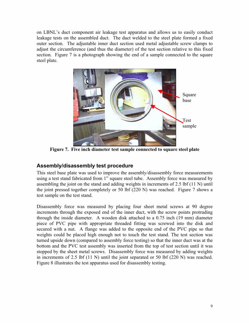
on LBNL’s duct component air leakage test apparatus and allows us to easily conduct leakage tests on the assembled duct. The duct welded to the steel plate formed a fixed outer section. The adjustable inner duct section used metal adjustable screw clamps to adjust the circumference (and thus the diameter) of the test section relative to this fixed section. Figure 7 is a photograph showing the end of a sample connected to the square steel plate.
Square base
Test sample
Figure 7. Five inch diameter test sample connected to square steel plate
Assembly/disassembly test procedure This steel base plate was used to improve the assembly/disassembly force measurements using a test stand fabricated from 1” square steel tube. Assembly force was measured by assembling the joint on the stand and adding weights in increments of 2.5 lbf (11 N) until the joint pressed together completely or 50 lbf (220 N) was reached. Figure 7 shows a test sample on the test stand. Disassembly force was measured by placing four sheet metal screws at 90 degree increments through the exposed end of the inner duct, with the screw points protruding through the inside diameter. A wooden disk attached to a 0.75 inch (19 mm) diameter piece of PVC pipe with appropriate threaded fitting was screwed into the disk and secured with a nut. A flange was added to the opposite end of the PVC pipe so that weights could be placed high enough not to touch the test stand. The test section was turned upside down (compared to assembly force testing) so that the inner duct was at the bottom and the PVC test assembly was inserted from the top of test section until it was stopped by the sheet metal screws. Disassembly force was measured by adding weights in increments of 2.5 lbf (11 N) until the joint separated or 50 lbf (220 N) was reached. Figure 8 illustrates the test apparatus used for disassembly testing.
9

Weights Gear clamp adjuster
Fixed section
Test sample
Fd
Adjustable inner ductsection
outer duct
Square base
Test stand
Figure 7. Apparatus used for assembly force testing
PVC pipe
Force
Weights
Flange
ixed outeruct section
Figure 8. Apparatus used for disassembly force t
Adjustable inner ductsection
esting
10
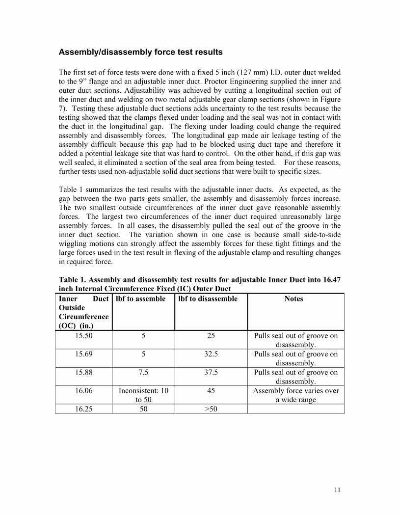
Assembly/disassembly force test results The first set of force tests were done with a fixed 5 inch (127 mm) I.D. outer duct welded to the 9” flange and an adjustable inner duct. Proctor Engineering supplied the inner and outer duct sections. Adjustability was achieved by cutting a longitudinal section out of the inner duct and welding on two metal adjustable gear clamp sections (shown in Figure 7). Testing these adjustable duct sections adds uncertainty to the test results because the testing showed that the clamps flexed under loading and the seal was not in contact with the duct in the longitudinal gap. The flexing under loading could change the required assembly and disassembly forces. The longitudinal gap made air leakage testing of the assembly difficult because this gap had to be blocked using duct tape and therefore it added a potential leakage site that was hard to control. On the other hand, if this gap was well sealed, it eliminated a section of the seal area from being tested. For these reasons, further tests used non-adjustable solid duct sections that were built to specific sizes. Table 1 summarizes the test results with the adjustable inner ducts. As expected, as the gap between the two parts gets smaller, the assembly and disassembly forces increase. The two smallest outside circumferences of the inner duct gave reasonable assembly forces. The largest two circumferences of the inner duct required unreasonably large assembly forces. In all cases, the disassembly pulled the seal out of the groove in the inner duct section. The variation shown in one case is because small side-to-side wiggling motions can strongly affect the assembly forces for these tight fittings and the large forces used in the test result in flexing of the adjustable clamp and resulting changes in required force. Table 1. Assembly and disassembly test results for adjustable Inner Duct into 16.47 inch Internal Circumference Fixed (IC) Outer Duct Inner Duct Outside Circumference (OC) (in.)
lbf to assemble lbf to disassemble Notes
15.50 5 25 Pulls seal out of groove on disassembly.
15.69 5 32.5 Pulls seal out of groove on disassembly.
15.88 7.5 37.5 Pulls seal out of groove on disassembly.
16.06 Inconsistent: 10 to 50
45 Assembly force varies over a wide range
16.25 50 >50
11

Because of the unreliability of the adjustable fitting, the next tests were performed using a series of fixed size inner ducts. Five fixed diameter inner ducts were supplied and tested with the same fixed outer duct. Table 2 shows similar results to the adjustable inner duct tests in Table 1, except that the test at 15.90 OC that is close to the adjustable test at 15.88 OC required greater forces. This is most likely because the fixed size fittings are more rigid than the adjustable fittings. Table 2. Assembly and disassembly test results for Fixed Inner Duct into 16.47 inch Internal Circumference Fixed Outer Duct Inner Duct Outside Circuference (in.)
lbf to assemble lbf to disassemble Notes
15.31 2.5 15 15.51 2.5 15 15.70 5 45 15.90 >50 >50 16.10 Could not assemble
Since many new and replacement duct systems use flexible ducting, the force it took to disassemble flexible ducting from a conventional inner duct and a PEGIT inner duct was also tested. The flex duct core was pulled over the PEGIT sheet metal inner duct with the rubber seal removed. A 0.3175 in. (8.1 mm) wide nylon tie-wrap was placed over the flex duct core and tightened into the groove (where the seal normally sits) in the PEGIT sheet metal fitting. A conventional (non-PEGIT) duct fitting was also tested. The results in Table 3 show that the PEGIT sheet metal fitting is as good as a conventional duct fitting for attaching flex duct cores. Table 3. Force required to remove flex duct from inner sheet metal duct Duct Type. lbf to Disassemble Notes Conventional Inner Duct 25
PEGIT 25 No seal. Tie-wrap aligned and tightened in groove
Air leakage test procedure We used our duct component air leakage test apparatus to determine the air leakage of the PEGIT fittings. It is similar to the system used in Phase 2, and uses the same high precision venturis. However, the apparatus used in Phase 3 differed by having a plenum to which test samples were connected. The plenum has a single square (9”×9” (230 mm×230 mm)) opening to which the square based samples were connected. This opening has a closed cell foam air seal and the box has a built in-pressure port. A baseline test was performed with the test plenum opening blocked to determine the background leakage of the system. The background leakage was subsequently subtracted from the total leakage measurements to obtain the leakage of the sample. This apparatus
12

and the associated calibration procedures made the leakage testing more precise and repeatable and also made comparisons to other duct fittings easier to carry out. The flow venturis were calibrated using a high precision mass flow controller. A set of flow venturis were used to cover a range of flow rates from about 0.05 cfm (0.02 L/s) to about 200 cfm (95 L/s). The test procedure uses a fan to pressurize the sample, with the flow meter located between the fan and the test sample. The leakage is measured at a pressure difference of 25 Pa. Because we could not always exactly match 25 Pa for each test, the airflow results from each test are corrected to the airflow at 25 Pa using Equation 1. We used a pressure exponent of 0.6 based on previous experiments (see Appendix 2) where similar samples were tested over a wide range of pressures and flow to determine their leakage characteristics. This pressure matching correction and the background leakage subtraction gave very small corrections, typically 0.1 cfm or less.
6.025)25(
∆
=measured
measured PQPaQ (1)
The leakage testing was conducted right after the joint was assembled using the assembly force testing procedure and before the disassembly testing. This method streamlined the testing process and made sure that the assembly that was leak tested was the same as the one force tested.
Air Leakage Test Results Table 4 summarizes the air leakage test results for the fixed diameter samples. As expected, the tighter the fit, the less the air leakage. For comparison, the previous tests conducted for phase one of this study showed that a conventional duct fitting carefully sealed with tape has leakage of about 0.5 cfm (0.22 L/s); this should be the maximum target leakage for the PEGIT system. The results show that this target is only met by one combination: the tightest one that could be assembled. However, this combination required greater then 50 lbf (220 N) of assembly force. All the combinations that could be assembled with 50 lbf or less force had too much leakage to be acceptable. Table 4. Fixed Inner Duct into 16.47 inch Inner Circumference Fixed Outer Duct
Inner Duct Outer
Circumference, in.
∆P Leak (Pa)
Venturi flow, cfm (L/s) at ∆P
Leak
Adjusted flow cfm (L/s) at 25Pa
15.31 24.3 7.4 (3.5) 7.5 (3.6) 15.51 25.4 3.2(1.5) 3.2 (1.5) 15.70 24.8 1.4 (0.7) 1.3 (0.6) 15.90 29.1 0.1 (0.1) 0.0 (0.0) 16.10 Could not be
assembled
13
Discussion and Conclusions During this study, the PEGIT system has been evaluated for air leakage and ease of assembly and disassembly. Ideally, the system would have as little leakage as possible, be easy to assemble and difficult to take apart. Significant changes were made by Proctor Engineering to the design of the PEGIT system to improve the air seal and ensure that it stayed in the sheet metal fitting. However, the final results indicate that achieving air leakage equal to or less than a conventional duct fitting sealed with tape requires such a tight fit between the inner and outer duct sections that the resulting assembly forces are greater than 50 lbf. This assembly force seems too large if systems are to be field assembled. The test results are also an indication of acceptable production tolerances. Changes in circumference of 0.2 in. (5 mm) gave significantly different air leakage and assembly force requirements. This implies that production tolerances for circumference need to be better than ±0.1 in. (2.5 mm) for consistent performance. This corresponds to diameter tolerances of ±0.03 in. (0.8 mm). For the connection to flex duct cores, conventional tie-wraps were used and the groove in the inner PEGIT duct fitting was used as the mechanical stop for the drawband, in place of the bead on conventional duct fittings. The tests showed that the PEGIT duct fitting gave as strong a mechanical connection as a conventional fitting. The following are three suggestions to improve the PEGIT fittings in the future:
• Use a softer formulation for the seal. • Change the seal profile to have a thin tip profile that will maintain an air seal
with looser fit between the inner and outer duct sections. • Use a lubricant on the seal (and possibly on the outer duct fitting) to make
assembly easier.
14

Acknowledgements The authors would like to thank Duo Wang and Cyril Guillot of the EPB group and Rob DeKeiffer and Skip Mandracchia of Proctor Engineering Group for their contributions to this work.
15

APPENDIX 1. Report on Initial PEGIT Design
Report for Proctor Engineering Group:
Evaluation of PEGIT Duct Connection System
June 1998
Iain S. Walker
Energy Performance of Buildings Group Lawrence Berkeley National Laboratory
Berkeley, CA 94720
16

Introduction This report outlines the laboratory measurements performed by LBNL on sample PEGIT duct fittings. In addition to discussing the measurement procedure and the test results, some comments on construction of the duct fittings will also be given. The duct fittings were designed by Proctor Engineering Group (PEG) as a method of connecting sections of forced air duct systems. The purpose of the fitting is to combine the mechanical connection and air seal. The mechanical connection is provided by the friction and interlocking of the rubber flange around the duct. The seal is provided by the pressing of the rubber flange against the inside of the mating duct surface. The tests in this report concentrate on the air sealing. The connections designed by PEG are for round metal duct connections. For connecting to flex duct, the round metal connection incorporates a collar that holds the inner liner of the flex duct against the rubber flange on the male part of the connection. After the collar is attached to the flex duct, it may be connected to other sheet metal components: plenums, register boots, other flex duct collars or sheet metal duct.
Sample Construction The test prototypes were prepared in LBNL sheet metal shops to PEG specifications. The major differences between these prototypes and those that would be used in mass production for commercial purposes are: • The prototypes had a different flange connection. Because of the difficulty in
forming the stainless steel to the complex shapes required of the fittings, the crimped lip that retains the rubber flange was of a different shape.
• The prototypes were fabricated from stainless steel. Production ducts and fittings
would of galvanized steel. • The prototypes were designed to be removable. To accomplish this, the clamping
mechanism used a hose clamp style of fastener that could be undone and reused. Production fittings would more likely have overcenter/one time clamps for the collars and no clamp for the duct to duct connection.
Although these are major construction differences, the results of these measurements can still be used to test the concept of the PEGIT system. In addition, the prototype duct sections had a single longitudinal seam that is common in sheet metal duct systems. This was chosen for convenience because it was easier to manufacture than a spiral duct for these prototypes that were made from scratch (flat sheet metal stock).
17
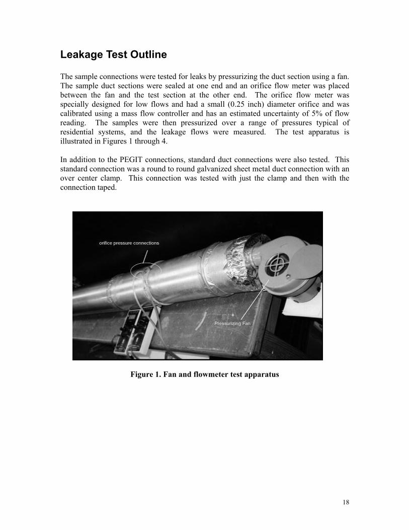
Leakage Test Outline The sample connections were tested for leaks by pressurizing the duct section using a fan. The sample duct sections were sealed at one end and an orifice flow meter was placed between the fan and the test section at the other end. The orifice flow meter was specially designed for low flows and had a small (0.25 inch) diameter orifice and was calibrated using a mass flow controller and has an estimated uncertainty of 5% of flow reading. The samples were then pressurized over a range of pressures typical of residential systems, and the leakage flows were measured. The test apparatus is illustrated in Figures 1 through 4. In addition to the PEGIT connections, standard duct connections were also tested. This standard connection was a round to round galvanized sheet metal duct connection with an over center clamp. This connection was tested with just the clamp and then with the connection taped.
Figure 1. Fan and flowmeter test apparatus
18

Figure 2. Whole test section
Figure 3. Duct to duct connection for PEGIT prototype
Figure 4. Duct to collar PEGIT prototype (for flex or plenum connection)
19

Measured Test Results The measured leakage data shown in Figures 5 through 8 have been least squares fitted to a power law relationship of the form:
nPCQ ∆= where Q is the flow rate (cfm), C is the flow coefficient (cfm/Pan), ∆P is the applied pressure difference (Pa) and “n” is the pressure exponent. The lines in the figures correspond to the results of the least squares fit. In addition, the leakage has been calculated in terms of flow at 25Pa (cfm25). The following table summarizes the results of this analysis. Connection type Flow Coefficient
(cfm/Pan) Pressure Exponent cfm25
PEGIT Duct-duct 0.0139 0.953 0.3 PEGIT Duct-flex 0.0646 0.843 1.0 Untaped Standard Duct-Duct 0.0942 0.894 1.7 Taped Standard Duct-Duct 0.0367 0.885 0.6 These results show that the PEGIT duct fittings have little leakage at the typical pressures seen in residential duct systems. The PEGIT Duct-Duct connection is at least as good as a taped standard connection, and considerably better than an untaped connection.
Duct to Duct PEGIT connection
0
0.1
0.2
0.3
0.4
0.5
0.6
0.7
0.8
0.9
1
0 10 20 30 40 50 60 70 80
Pressure Difference, Pa
Leak
age
Flow
, cfm
Figure 5. Measured pressurization test results for the duct-duct connection.
20

Duct to Flex PEGIT connection
0
0.2
0.4
0.6
0.8
1
1.2
0 5 10 15 20 25 30
Pressure Difference, Pa
Leak
age
Flow
, cfm
Figure 6. Pressurization test results for the duct-flex collar connection.
Standard ConnectionTaped
0
0.2
0.4
0.6
0.8
1
1.2
0 10 20 30 40 5
Pressure, Pa
Flow
, cfm
0
21

Figure 7. Pressurization test results for a standard sheet metal duct connection (taped).
Standard ConnectionUntaped
0
0.2
0.4
0.6
0.8
1
1.2
1.4
0 5 10 15 20
Pressure, Pa
Flow
, cfm
Figure 8. Pressurization test results for a standard sheet metal duct connection (untaped)
22

An additional comparison can be made to the data given in the ASHRAE Fundamentals Handbook (ASHRAE 1997, p. 32.16-32.17). The handbook gives duct leakage values for longitudinal seams and per unit surface area and NO information regarding connections (where most of the leaks actually are). For the purposes of this comparison we will assume that the leakage for a 5m (16ft) duct run of 15 cm (8 inch) diameter round sheet metal duct is all at the connection. The leakage rate is given as 0.15 l/sm2 at 250 Pa for sealed and 1.5 l/sm2 for unsealed. The total surface area is 2.4 m2, so the corresponding leakage rates are 0.36 l/s and 3.6 l/s for sealed and unsealed cases. Converting to 25 Pa from 250 Pa (and assuming a pressure exponent of 0.7) gives 0.07 l/s (0.15 cfm25) and 0.7 l/s (1.5 cfm25). Thus the tested PEGIT connection is much better than the ASHRAE requirement for unsealed ducts and almost as good as the “sealed case”, particularly given that the ASHRAE data is not for connections per se.
Comments and Conclusions The biggest problem with the prototypes tested here was the connection of the rubber flange to the round duct. The lip to hold the flange was not well formed and resulted in a couple of problems. The first problem was that the flange was not securely held in the lip. Combined with the grippiness of the rubber, this led to the flange being pulled out of the crimped lip in the round sheet metal as it was inserted in another duct section or the clamping mechanism. If the flange is incorrectly seated in this way, it can result in additional connection leakage. A possible solution to this problem is to have a more positive lock to keep the rubber flange in the crimped socket by pinching (using a punch mechanism) the sheet metal together at locations around the crimp. A stronger version of this may have a hole punched all the way through. This would add another step to the manufacturing process, however, it is necessary because the integrity of both the seal and the mechanical connection depend on the flange being properly connected. Alternatively, a lubricant could be applied (at the factory, not by the installer) to the flange so that the connection slides together with less friction. The problems to be overcome with this method would be finding a lubricant that does not dry out in storage and does not interact with the rubber flange. The second problem with the flange was that it was not held at the correct angle. This angle can be critical for achieving a proper seal because it is a factor in determining the outward pressure that rubber flange against the metal surface. In addition, this angle is critical in determining the forces required to assemble or dissemble the duct sections. With regards to mechanical security of the connection, the test samples have adjustable clamps so the it was not possible to evaluate the security of a production fitting, however, the basic concept provides a good mechanical connection that is very difficult to pull apart (probably not possible with flex duct without destroying the flex duct itself). This means that it meets the intent of the Uniform Mechanical Code (UMC (1994)) which states that sheet metal duct connections must be secured using three sheet metal screws
23

“... or an equivalent fastening method.”. Given that the UMC does not give any specifications for the strength of the duct connection there is no reason to believe that the PEGIT system should not be acceptable. It should be noted that the UMC requirement is rarely met in residential duct installations. In addition, the PEGIT system is simpler to install than attaching three sheet metal screws, particularly in the limited access spaces that HVAC systems are commonly installed in for residences.
References ASHRAE. 1997. 1997 ASHRAE Handbook of Fundamentals. ASHRAE. Atlanta. GA. p. 32.16-32.17 Uniform Mechanical Code. 1994. International Conference of Building Officials. Whittier, CA. Paragraph 601.5.1.
24

Summary of Fire testing for duct seals. The following UL standards apply: UL 181 “Standard for Factory Made Air Ducts and Connectors”, (Underwriters Laboratories, Inc. Northbrook, Illinois, USA, 1994). UL 181A “Standard for Closure Systems for use With Rigid Air Ducts and Air Connectors”, (Underwriters Laboratories, Inc. Northbrook, Illinois, USA., 1993). UL 181B “Standard for Closure Systems for use with Flexible Air Ducts and Air Connectors”, 1st Edn (Underwriters Laboratories, Inc. Northbrook, Illinois, USA, 1995). Includes ratings for 181B-FX Flexible Tape and 181B-M Mastic. UL 214 “Standard for tests for Flame Propogation of Fabrics and Films” UL 723 “ Standard for test for Surface Burning Characteristics of Building Materials” UL 181 This standard is for factory assembled duct systems and has more fire resistance testing than 181A or 181B. There are four tests in UL 181: 1. Surface Burning Characteristic. The surface burning test is performed according to
another UL standard: UL 723 “ Standard for test for Surface Burning Characteristics of Building Materials”. This test does not look like it applies to the PEGIT connection because the test uses a sealant on a piece of rigid cement board.
2. Flame Resistance. The flame resistance test is another UL test UL 214 “Standard for tests for Flame Propagation of Fabrics and Films”. This is unlikely to apply to the PEGIT connection because there is no “fabric or film”.
3. Flame Penetration. A section of duct wall material is used to form one wall of a furnace.
4. Burning. Samples are exposed to a naked bunsen burner flame. The samples are held at an angle such that any melted seal will run out of the sample and be caught on a cotton cloth. The cotton cloth must not ignite when the seal falls onto it. The bunsen flame is half yellow and so it is not the hottest it could be (although the actual temperatures used are not controlled!).
The attached pages from the UL standard show how these tests are performed. If the PEGIT system does not include the air ducts and is just the connectors, then, as table 4.1 in the attached material shows, the burning and surface burning test apply to air connectors and the flame resistance test applies to joining materials. The flame penetration test is for flat sections of duct wall and will not apply to the PEGIT system.
25

UL 181A UL 181A only has the Burning test from UL181. However, the test is adapted to be specific for three types of sealants. Section 11 describes the test for metal foil tapes on cement board, Section 22 is for metal foil tapes on Duct Board and Section 34 applies to mastic. In each case the sealant is directly exposed to the flame and is not applied to a duct seam, it is just applied to a flat surface. For the PEGIT system a section of duct containing a joint would have to be exposed to the flame because the seal itself is between sheet metal surfaces and not directly exposed to the flame. Or it could be argued that this test is irrelevant BECAUSE none of the seal is directly exposed to flame.
UL 181B UL181B has the UL723 surface burning characteristic test. AS with the burning test the selant is simply applied to flat piece of cement board. This is also a situation that is not really applicable to the PEGIT system.
Summary The only test with any relevance for the PEGIT system is the burning test. We can try to evaluate the materials used in the PEGIT system by doing this test in a fume hood where we expose a PEGIT seal to a naked bunsen flame and see what happens. This has been done previously for the aerosol sealant.
26

Appendix 2.
Status report on Evaluation of PEGIT Connection System July 2002 The sample PEGIT connection used for these tests is a 5-inch round-to-round sheet metal connection. The connection has two parts: a smaller diameter male section including a rubber sealing/locking ring that slides into a second female section of larger diameter. The results for the test sample indicate that large assembly forces are required (greater than 600 N). For ease of field assembly, these forces will need to be reduced. This can be achieved by making the rubber seal smaller or more flexible (particularly as the force required to pull the connection apart is also very high). If the gap between the male and female sheet metal sections were made larger, this would also allow for lower connection forces.
Assembly Force We used two different methods to assess the force required to push the two parts of the connection together.
1. Placing weight on the sample A simple method of loading the connection that allows large cumulative weights, while allowing very small increments is to add water to a bucket placed on top the sample connection. This method also ensures that the round sheet metal section was loaded evenly around the circumference. This even loading allows the testing to be both safe and stable. However, we found that even with a full bucket of water the connection was not pushed together. The bucket and water had a combined weight of 20.35 kg or 45.0lb (determined using a digital scale) representing an assembly force of 200 N.
2. Direct loading on a scale In this second test, the sample was placed on a scale and was loaded by having a technician push on the end of the sample (see Figure 1). It was found that a load of (65.6 kg) 145 lb was required representing an assembly force of 644 N. Even at this high loading it is necessary to wiggle the fitting from side to side to ease the sliding of the female section over the rubber ring seal.
Force required to pull the connection apart To pull the connection apart, it was suspended from a scale to record the applied force. A lever was used to apply a load by pulling down in on the other end of the connection. This allowed us to safely place large loads the connection. When the connection separates, it will do so rapidly, and this system does not place the technician directly in line with the connection. Figure 2 is a photograph of this experimental apparatus. The
27

connection was loaded with up to 110 lb (49.8 kg) or 488 N of separation force, but did not separate. We stopped testing at this load for safety reasons and because this is far in excess of any separation force we can reasonably imagine would be applied in a field installation.
Figure 1. Pressing together the adjustable PEGIT duct fitting on a scale
Load Scale
Sample Connection
Lever to applyload
Figure 2. Separation load testing of PEGIT duct fitting
28

Leakage Test The leakage of the connection was measured using LBNL’s standard test apparatus for measuring low leakage flow of duct connections. It consists of a variable speed fan, a set of accurate orifices, with different sized orifices used for different flow rates. The connection is capped at one end and the other end is connected to the test apparatus – as shown in Figure 3. The sample was tested over a range of pressures, with the leakage flow recorded at each pressure. The results of these tests are shown in Figure 4. The leakage flow at 25 Pa pressure difference is 0.26 cfm. This is very close to the 0.3 cfm at 25 Pa measured for a previous iteration of the test connection about three years ago. This is a very low level of leakage and is about one half the leakage measured for a well taped connection of a similar configuration.
Sample Connection
Air flowmeasurement orifice
Air flowfrom fan
Figure 3. Test apparatus for leakage testing.
Fitted data:Flow (cfm) = 0.0347Pressure(pa)0.6254
0.00
0.05
0.10
0.15
0.20
0.25
0.30
0.35
0.40
0.45
0 10 20 30 40 50 6
Imposed Pressure Difference, Pa
Leak
age
Flow
, cfm
0
Figure 4. Results of leakage testing
29
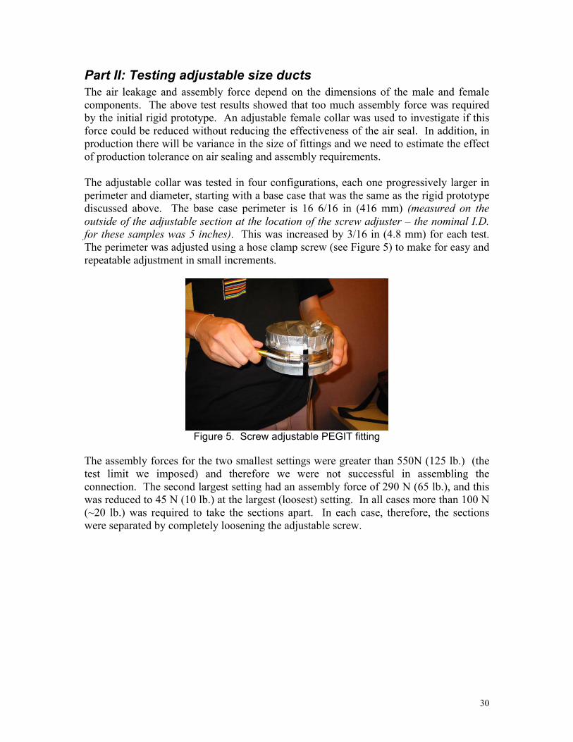
Part II: Testing adjustable size ducts The air leakage and assembly force depend on the dimensions of the male and female components. The above test results showed that too much assembly force was required by the initial rigid prototype. An adjustable female collar was used to investigate if this force could be reduced without reducing the effectiveness of the air seal. In addition, in production there will be variance in the size of fittings and we need to estimate the effect of production tolerance on air sealing and assembly requirements. The adjustable collar was tested in four configurations, each one progressively larger in perimeter and diameter, starting with a base case that was the same as the rigid prototype discussed above. The base case perimeter is 16 6/16 in (416 mm) (measured on the outside of the adjustable section at the location of the screw adjuster – the nominal I.D. for these samples was 5 inches). This was increased by 3/16 in (4.8 mm) for each test. The perimeter was adjusted using a hose clamp screw (see Figure 5) to make for easy and repeatable adjustment in small increments.
Figure 5. Screw adjustable PEGIT fitting
The assembly forces for the two smallest settings were greater than 550N (125 lb.) (the test limit we imposed) and therefore we were not successful in assembling the connection. The second largest setting had an assembly force of 290 N (65 lb.), and this was reduced to 45 N (10 lb.) at the largest (loosest) setting. In all cases more than 100 N (~20 lb.) was required to take the sections apart. In each case, therefore, the sections were separated by completely loosening the adjustable screw.
30

0
0.5
1
1.5
2
2.5
3
3.5
4
4.5
5
0 10 20 30 40 50 60 7
Imposed Pressure Difference, Pa
Leak
age
flow
, cfm
0
perimeter4 : 16 15/16 inperimeter3 : 16 13/16 inperimeter 2 : 16 9/16 inperimeter 1 : 16 6/16 in
Figure 6. Dependence of air leakage on fitting tightness
The air tightness of the adjustable fitting was determined using the same method and apparatus as for the rigid prototype discussed above. Figure 6 shows the expected result that the larger perimeter results in greater air leakage, and the 25 Pa air leakage flows are summarized in Table 1. The two larger perimeters that had more reasonable assembly forces both have more than 1 cfm of leakage at 25 Pa – which is probably unacceptably large. The smallest perimeter tested had about the same leakage at 25 Pa as the rigid prototype.
Table 1. Air Leakage Flow Results For Adjustable Collar Perimeter (inches)
16 6/16 16 9/16 16 13/16 16 15/16
Air Leakage Flow at 25 Pa
0.36 0.75 1.22 2.70
It appears, that with this particular seal shape that we cannot get a reasonable compromise between assembly force and sealing. After inspecting the seal there is a possibility that changing the seal shape to make the material thinner and/or more flexible may improve this situation.
31