evaluation of rtk-gps performance with low-cost...
TRANSCRIPT

Evaluation of RTK-GPS Performance withLow-cost Single-frequency GPS Receivers
Tomoji Takasu, Akio YasudaTokyo University of Marine Science and Technology, Japan
BIOGRAPHY
Tomoji Takasu is a researcher in Funai Laboratory ofSatellite Navigation at Tokyo University of MarineScience and Technology. He was working fordevelopments of satellite systems at NEC Aerospacesystems Ltd. from 1984 to 1997. He is currently involvedin the research and development of precise positioningalgorithms with GPS/GNSS, including PPP, RTK-GPSand INS/GPS integration.
Akio Yasuda graduated in 1966 from Dept. of ElectricalEng., Nagoya Institute of Technology, and obtained Dr. ofEng. degree from Nagoya University, and worked atNagoya University and at Tokyo University of MercantileMarine. Since 2004, he was Prof. at Tokyo University ofMarine Science and Technology. He is currentlyconductor of Funai laboratory of Satellite Navigation. Hewas engaged in research on development of marine wavemeter, BS and GMS reception onboard, regionalpositioning system with geostationary satellites. Hisconcerning of GPS started in 1987. He is presentlyconducting the researches on multipath mitigation,analysis of ionospherical delay, improvement of RTK-GPS algorism, and the other GPS related subjects. He is amember of IEICE (fellow), Japan Inst. Navigation, IONand IEEE.
ABSTRACT
It has been considered that low-cost single-frequencyGPS antenna and receiver are not applicable to precisepositioning by RTK-GPS. In this study, to confirm theRTK-GPS performance with such low-cost antenna andreceiver, some field tests were conducted. At first, byusing the field calibration method, the antenna PCV(phase center variation), carrier-phase multipath and codemultipath were measured with various combination ofantennas and receivers. Next, the RTK-GPS performance,including the positioning accuracy, fix-rate and TTFF forambiguity resolution, was evaluated. According to theresults of the experiments, these antenna and receiver arefeasible for RTK-GPS but some attention should be paidfor practical performance.
INTRODUCTION
RTK-GPS (realtime kinematic GPS) is one of the mostprecise positioning technologies, with which users canobtain cm-level accuracy of the position in real-time byprocessing carrier-phase measurements of GPS signals. Itis generally considered that geodetic-grade dual-frequency GPS antenna and receiver are necessary toachieve practical performance of RTK-GPS. Low-costsingle-frequency GPS antenna and receiver are notapplicable to RTK-GPS because of their poorperformance. However, geodetic-grade antenna andreceiver have been still expensive compared to consumer-grade ones. This is one of the reasons why RTK-GPS isstill not popular and is utilized only for limitedapplications like land survey. If the low-cost antenna andreceiver were available for RTK-GPS, larger number ofusers, who need more precise positions, would intend touse the technique. More applications of RTK-GPS,currently not applicable due to cost issues, would becomepractical. The objective of this study is to evaluate theperformance of RTK-GPS with low-cost single-frequencyantenna and receiver and to clarify issues to apply them toRTK-GPS.
EVALUATION OF ANTENNAS AND RECEIVERSBY FIELD CALIBRATION
The field calibration is often used for evaluation of GPSantennas. According to the technique, a target antenna ismounted on a field with good sky view. A referenceantenna is placed in the vicinity of the target as well. Bothof the antennas are connected to receivers to record rawmeasurement data of GPS signals in a certain periodtypically 24 hours. Recorded data are processed togetherby a post-mission analysis to obtain the antenna phasecenter position and PCV. In this study, some field testswere conducted to evaluate the performances of low-costantenna and receiver with the method. In addition to theantenna phase center position and PCV, carrier-phasemultipaths and code multipaths were also extracted in thesame time. By using dual-frequency antenna and receiveras reference, the characteristics of single-frequencyantenna and receiver were obtained. Figure 1 shows the

configuration of the field test. The target antenna wasmounted on a ground-plane of 21 cm diameter to suppressmultipaths. The baseline length between the target and thereference antennas was approximately 1 m. For eachcombination of antenna and receiver, raw GPSmeasurement data are sampled at the rate of 1 Hz for 24hours. The recorded raw measurement data were analyzedto evaluate the performance of antenna and receiver bythe following way.
ESTIMATION OF ANTENNA PHASE CENTER/VARIATION AND CARRIER-PHASE MULTIPATH
By using EKF (extended Kalman filter) [1], a state vectorx and its covariance matrix P can be estimated by:
1))))(ˆ()())(ˆ())((ˆ()(
)()))(ˆ(()())(ˆ()(ˆ)(ˆ
−+−−−−−=
−−−=+
−+−=+
RxHPxHxHPK
PxHKIPxυKxx
Tkkkkkk
kkkk
kkkk
(1)
where )(xυ , )(xH and R are the residual vector, thematrix of partial derivatives and the covariance matrix ofmeasurement errors, respectively. Assuming the systemmodel stationary and no system noise, the time updatefrom kt to 1+kt of EKF is just expressed as:
)(ˆ)(ˆ 1 +=−+ kk xx , )()(1 +=−+ kk PP (2)
At first, the antenna phase center position is determinedby the following way. The state vector is defined as:
Tmururur
Tu NNN ),...,,,( 21rx = (3)
With single-differenced residuals of carrier-phase
measurements, the double-differenced residuals, thepartial derivatives and the covariance of measurementerrors are expressed as:
)()( , xυDxυ kurk = )()( xDHxH ur= , TurDDRR = (4)
⎟⎟⎟⎟⎟
⎠
⎞
⎜⎜⎜⎜⎜
⎝
⎛
+−
+−+−
=
)(
)()(
)(222
11,
1
mur
mur
mur
ururur
urkurur
ur
N
NN
ρλφ
ρλφρλφ
xυ
⎟⎟⎟⎟⎟
⎠
⎞
⎜⎜⎜⎜⎜
⎝
⎛
−
−−
=
100
010001
)(2
1
mu
u
u
ur
e
ee
xH
)2,...,2,2(diag 222φφφ σσσ=urR
ri
uii
ur rrrr −−−=ρ , ui
uii
u rrrre −−= /)(
where:ur() : single-difference between target and reference
antennasur : target antenna phase center position (m)rr : reference antenna phase center position (m)ir : satellite i position (m)λ : carrier wave length (m)
iuφ : carrier-phase measurement (cycle)iuρ : geometric range (m)iuN : carrier-phase ambiguity (m)
iue : LOS (line of sight) vectorφσ : standard deviation of carrier-phase
measurement error (m)
⎟⎟⎟⎟⎟
⎠
⎞
⎜⎜⎜⎜⎜
⎝
⎛
−
−−
=
1001
01010011
D : single-differencing matrix
By solving the EKF formula (1), (2) with equation (4), thephase center position of the target antenna is obtained asthe final solution of ur̂ . In this case, the carrier-phaseambiguities are not fixed to integers.
In the next step, the target antenna PCV is estimated. Thestate vector is defined as:
TTmururur NNN ),,...,,( 21 cx = (5)
where c is a coefficient vector defined as:
Tscscsc ccccccccc ,...),,,,,,,,( 302222212120111110=c (6)
ReferenceReceiver
(Dual-frequency)
TargetReceiver
PC (Data Logger)
ReferenceAntenna
(Dual-frequency)
Target Antenna
AntennaMount with
Ground Plane
GPS Satellite
Approx. 1 m
Figure 1. Configuration for evaluation of the antenna andreceiver performance by field test
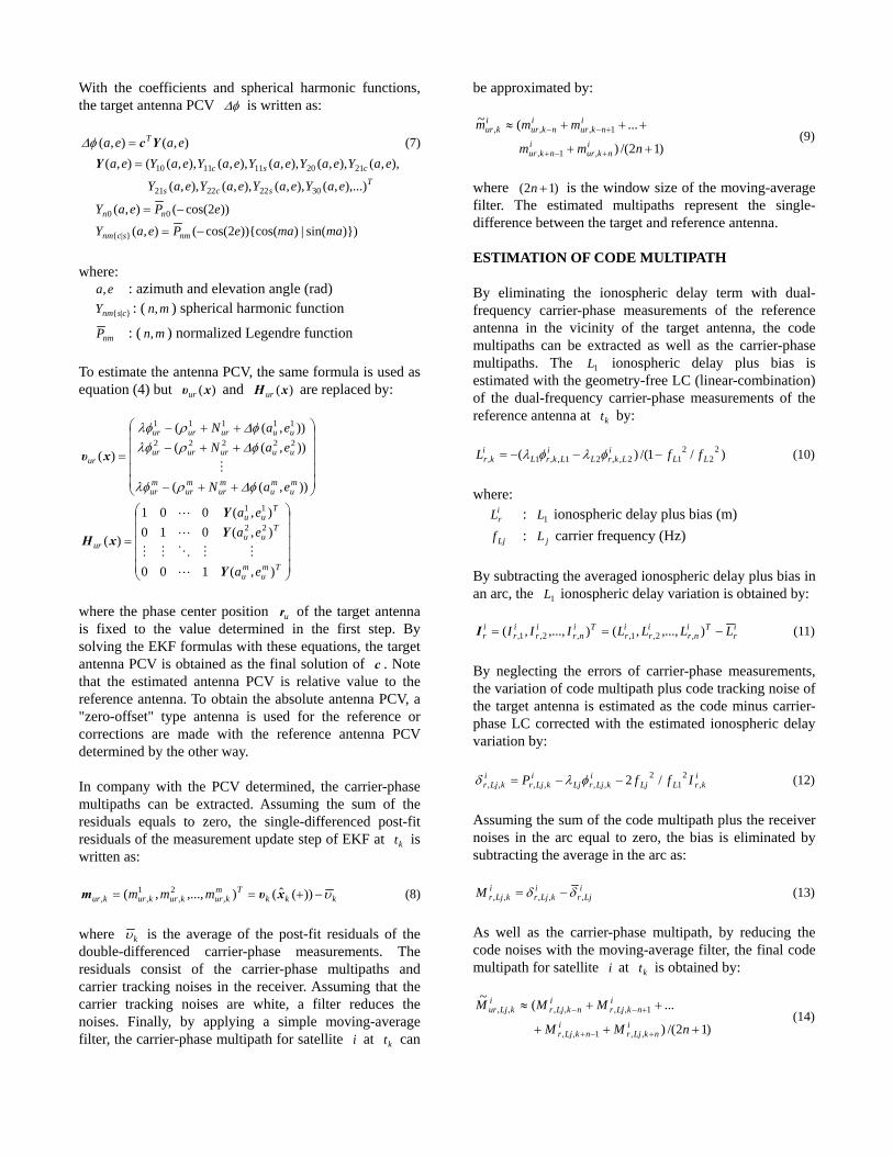
With the coefficients and spherical harmonic functions,the target antenna PCV φΔ is written as:
),(),( eaea TYc=φΔ (7)
Tscs
csc
eaYeaYeaYeaY
eaYeaYeaYeaYeaYea
),...),(),,(),,(),,(
),,(),,(),,(),,(),,((),(
30222221
2120111110=Y
)})sin(|))){cos(2cos((),(
))2cos((),(
}|{
00
mamaePeaY
ePeaY
nmscnm
nn
−=
−=
where:ea, : azimuth and elevation angle (rad)
}|{ csnmY : ( mn, ) spherical harmonic function
nmP : ( mn, ) normalized Legendre function
To estimate the antenna PCV, the same formula is used asequation (4) but )(xυur and )(xHur are replaced by:
⎟⎟⎟⎟⎟
⎠
⎞
⎜⎜⎜⎜⎜
⎝
⎛
++−
++−++−
=
)),((
)),(()),((
)(22222
11111
mu
mu
mur
mur
mur
uuururur
uuururur
ur
eaN
eaNeaN
φΔρλφ
φΔρλφφΔρλφ
xυ
⎟⎟⎟⎟⎟
⎠
⎞
⎜⎜⎜⎜⎜
⎝
⎛
=
Tmu
mu
Tuu
Tuu
ur
ea
eaea
),(100
),(010),(001
)(22
11
Y
YY
xH
where the phase center position ur of the target antennais fixed to the value determined in the first step. Bysolving the EKF formulas with these equations, the targetantenna PCV is obtained as the final solution of c . Notethat the estimated antenna PCV is relative value to thereference antenna. To obtain the absolute antenna PCV, a"zero-offset" type antenna is used for the reference orcorrections are made with the reference antenna PCVdetermined by the other way.
In company with the PCV determined, the carrier-phasemultipaths can be extracted. Assuming the sum of theresiduals equals to zero, the single-differenced post-fitresiduals of the measurement update step of EKF at kt iswritten as:
kkkTm
kurkurkurkur mmm υ−+== ))(ˆ(),...,,( ,2
,1
,, xυm (8)
where kυ is the average of the post-fit residuals of thedouble-differenced carrier-phase measurements. Theresiduals consist of the carrier-phase multipaths andcarrier tracking noises in the receiver. Assuming that thecarrier tracking noises are white, a filter reduces thenoises. Finally, by applying a simple moving-averagefilter, the carrier-phase multipath for satellite i at kt can
be approximated by:
)12/()
...(~
,1,
1,,,
++
+++≈
+−+
+−−
nmm
mmmi
nkuri
nkur
inkur
inkur
ikur (9)
where )12( +n is the window size of the moving-averagefilter. The estimated multipaths represent the single-difference between the target and reference antenna.
ESTIMATION OF CODE MULTIPATH
By eliminating the ionospheric delay term with dual-frequency carrier-phase measurements of the referenceantenna in the vicinity of the target antenna, the codemultipaths can be extracted as well as the carrier-phasemultipaths. The 1L ionospheric delay plus bias isestimated with the geometry-free LC (linear-combination)of the dual-frequency carrier-phase measurements of thereference antenna at kt by:
)/1/()( 22
212,,21,,1, LL
iLkrL
iLkrL
ikr ffL −−−= φλφλ (10)
where:irL : 1L ionospheric delay plus bias (m)
Ljf : jL carrier frequency (Hz)
By subtracting the averaged ionospheric delay plus bias inan arc, the 1L ionospheric delay variation is obtained by:
ir
Tinr
ir
ir
Tinr
ir
ir
ir LLLLIII −== ),...,,(),...,,( ,2,1,,2,1,I (11)
By neglecting the errors of carrier-phase measurements,the variation of code multipath plus code tracking noise ofthe target antenna is estimated as the code minus carrier-phase LC corrected with the estimated ionospheric delayvariation by:
ikrLLj
ikLjrLj
ikLjr
ikLjr IffP ,
21
2,,,,,, /2−−= φλδ (12)
Assuming the sum of the code multipath plus the receivernoises in the arc equal to zero, the bias is eliminated bysubtracting the average in the arc as:
iLjr
ikLjr
ikLjrM ,,,,, δδ −= (13)
As well as the carrier-phase multipath, by reducing thecode noises with the moving-average filter, the final codemultipath for satellite i at kt is obtained by:
)12/()
...(~
,,1,,
1,,,,,,
+++
++≈
+−+
+−−
nMM
MMMi
nkLjri
nkLjr
inkLjr
inkLjr
ikLjur (14)
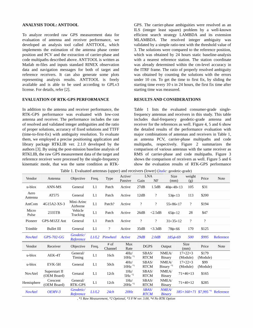
ANALYSIS TOOL: ANTTOOL
To analyze recorded raw GPS measurement data forevaluation of antenna and receiver performance, wedeveloped an analysis tool called ANTTOOL, whichimplements the estimation of the antenna phase centerposition and PCV and the extraction of carrier-phase andcode multipaths described above. ANTTOOL is written asMatlab m-files and inputs standard RINEX observationdata and navigation messages for both of target andreference receivers. It can also generate some plotsrepresenting analysis results. ANTTOOL is freelyavailable and is able to be used according to GPLv3license. For details, refer [2].
EVALUATION OF RTK-GPS PERFORMANCE
In addition to the antenna and receiver performance, theRTK-GPS performance was evaluated with low-costantenna and receiver. The performance includes the rateof resolved and validated integer ambiguities and the ratioof proper solutions, accuracy of fixed solutions and TTFF(time-to-first-fix) with ambiguity resolution. To evaluatethem, we employed a precise positioning application andlibrary package RTKLIB ver. 2.1.0 developed by theauthors [3]. By using the post-mission baseline analysis ofRTKLIB, the raw GPS measurement data of the target andreference receiver were processed by the single-frequencykinematic mode, that was the same condition as RTK-
GPS. The carrier-phase ambiguities were resolved as anILS (integer least square) problem by a well-knownefficient search strategy LAMBDA and its extensionMLAMBDA. The resolved integer ambiguity wasvalidated by a simple ratio-test with the threshold value of3. The solutions were compared to the reference position,which was obtained by 24 hours static baseline-analysiswith a nearest reference station. The station coordinatewas already determined within the cm-level accuracy inthe ITRF frame. The ratio of properly resolved ambiguitywas obtained by counting the solutions with the errorsunder 10 cm. To get the time to first fix, by sliding thestarting time every 10 s in 24 hours, the first fix time afterstarting time was measured.
RESULTS AND CONSIDERATIONS
Table 1 lists the evaluated consumer-grade single-frequency antennas and receivers in this study. This tableincludes dual-frequency geodetic-grade antenna andreceiver for the references as well. Figure 4, 5 and 6 showthe detailed results of the performance evaluation withmajor combinations of antennas and receivers in Table 1,as antenna PCV, carrier-phase multipaths and codemultipaths, respectively. Figure 2 summarizes thecomparison of various antennas with the same receiver asRMS of carrier-phase and code multipaths. Figure 3shows the comparison of receivers as well. Figure 5 and 6show the evaluation results of RTK-GPS performance
Table 1. Evaluated antennas (upper) and receivers (lower) (italic: geodetic-grade)LNAVendor Antenna Objective Freq. Type Active/
Passive Gain NFSize(mm)
weight(g) Price Note
u-blox ANN-MS General L1 Patch Active 27dB 1.5dB 40φ×48×13 105 $31
AeroAntenna AT575 General L1 Patch Active 12dB ? 53φ×13 113 $200
AntCom 4G15A2-XS-3 Mini-ArincAirborne L1 Patch? Active ? ? 55×86×17 ? $194
MicroPulse 2335TB Vehicle
Tracking L1 Patch Active 26dB <2.5dB 65φ×12 28 $47
Pioneer GPS-M1ZZ Ant General L1 Patch Active ? ? 31×35×12 ? ?
Trimble Bullet III General L1 ? Active 35dB <3.3dB 78φ×66 170 $125
NovAtel GPS-702-GG Geodetic/Reference L1/L2 Pinwheel Active 29dB 2.0dB 185φ×69 500 $995 Reference
Vendor Receiver Objective Freq. # ofChannel
MaxRate DGPS Output Size
(mm) Price Note
u-blox AEK-4T General/Timing L1 16ch 4Hz/
10Hz *1SBAS/RTCM
NMEA/Binary
17×22×3(Module)
$179(Module)
u-blox EVK-5H General L1 50ch 4Hz/10Hz *1
SBAS/RTCM
NMEA/Binary *3
17×22×3(Module)
$99(Module)
NovAtel Superstart II(OEM Board) Genaral L1 12ch 1Hz/
5Hz *2SBAS/RTCM
NMEA/Binary 71×46×13 $165
Hemisphere Crescent(OEM Board)
General/RTK-GPS L1 12ch 1Hz/
20Hz *2SBAS/RTCM
NMEA/Binary 71×40×12 $285
NovAtel OEMV-3 Geodetic/Reference L1/L2 24ch 20Hz SBAS/
RTCMNMEA/Binary 185×160×71 $7,995 *4 Reference
, *1 Raw Measurement, *2 Optional, *3 F/W ver. 3.00, *4 No RTK Option

with the same combinations, as the time series ofeast/north/up position errors and TTFF with ambiguityresolution. Table 2 summarizes the RTK-GPSperformance. According to these results, the difference ofthe antenna performances is large between geodetic-gradeand consumer-grade, especially for the phase centerstability and code multipath. Generally, code multipathmuch affects to the performance of the RTK-GPSinitialization. To improve TTFF, it might be effective toreplace a low-cost antenna with geodetic-grade one. Bycontrast, the difference of receivers is not so large. The
carrier-phase multipath level of consumer-grade receiversis almost same as geodetic-grade. Therefore, thepositioning accuracy of RTK-GPS would be sufficienteven with consumer-grade receiver. Dual-frequencyreceivers, however, have an advantage of much shortertime of ambiguity resolution, ideally instantaneous. Theresults of TTFF test indicate that at least a few minutes arenecessary for the first fix with a single-frequency receiver.So, in the environment with many cycle slips like formobile vehicle navigation, a dual-frequency receiver isstill necessary. Though, for the application withcontinuous observation like crustal deformationmonitoring, low-cost single-frequency receiver could beapplicable for short baseline RTK-GPS.
CONCLUSIONS
In this study, The RTK-GPS performance with low-costsingle-frequency antenna and receiver were evaluated bysome field tests. According to the results of theexperiments, it is feasible to apply consumer-gradeantenna and receiver to RTK-GPS. With a low-costantenna, however, performance degradation is large, soreplacing it with a geodetic-grade antenna is mucheffective to improve the performance. By contrast, as toreceivers, the performance difference is smaller betweenthe consumer-grade and the geodetic-grade.
REFERENCES
[1] A.Gelb ed., Applied Optimal Estimation, The M.I.T.Press, London, 1974
[2] GPS L1 Antenna/Receiver Evaluation - Analysis Tool.URL: http://gpspp.sakura.ne.jp/anteva/anttool.htm
[3] T.Takasu et al., N.Kubo and A.Yasuda, Development,evaluation and application of RTKLIB: A programlibrary for RTK-GPS, GPS/GNSS symposium 2007,Tokyo, Japan, 20-22 November, 2007 (in Japanese)
0
0.2
0.4
0.6
0.8
1
AN
N-M
S
AT5
75
4G15
A2-
XS
-3
2335
TB
GP
S-M
1ZZ
Ant
Bul
let I
II
GP
S-7
02-G
G 0
0.2
0.4
0.6
0.8
1
AN
N-M
S
AT5
75
4G15
A2-
XS
-3
2335
TB
GP
S-M
1ZZ
Ant
Bul
let I
II
GP
S-7
02-G
G
Figure 2. Comparison of antennas with the same receiver,phase multipath (cm) (left) and code multipath (m) (right)
0
0.2
0.4
0.6
0.8
1
AE
K-4
T
EV
K-5
H
Sup
erS
tar I
I
Cre
scen
t
OE
MV
-3 0
0.2
0.4
0.6
0.8
1
AE
K-4
T
EV
K-5
H
Sup
erS
tar I
I
Cre
scen
t
OE
MV
-3
Figure 3. Comparison of receivers with the same antenna,phase multipath (cm) (left) and code multipath (m) (right)
Table 2. Summary of RTK-GPS performances (italic: geodetic-grade)Rover Ambiguity Resolution RMS Error of Fixed Solution TTFF with AR
Antenna Receiver Fix-Rate Success- Rate E-W N-S U-D Mean 95% MaxANN-MS OEMV-3 94.8 % 99.8 % 0.47 cm 0.53 cm 1.09 cm 968.5 s 3010.0 s 6310.0 s
AT575 OEMV-3 98.3 % 99.7 % 0.34 cm 0.42 cm 0.90 cm 436.7 s 1370.0 s 3500.0 s4G15A2-XS-3 OEMV-3 96.8 % 99.8 % 0.41 cm 0.49 cm 1.12 cm 514.4 s 1650.0 s 3260.0 s
2335TB OEMV-3 98.4 % 99.6 % 0.38 cm 0.47 cm 1.10 cm 535.8 s 1550.0 s 2940.0 sGPS-M1ZZ Ant OEMV-3 97.1 % 99.5 % 0.45 cm 0.56 cm 1.15 cm 983.2 s 3910.0 s 6600.0 s
Bullet III OEMV-3 99.4 % 99.8 % 0.30 cm 0.47 cm 1.04 cm 256.8 s 816.0 s 2200.0 sGPS-702-GG AEK-4T 99.9 % 100.0 % 0.26 cm 0.34 cm 0.81 cm 131.2 s 490.0 s 1200.0 sGPS-702-GG EVK-5H 0.0 % 0.0 % - - - - - -GPS-702-GG Superstar II 99.6 % 100.0 % 0.28 cm 0.39 cm 0.85 cm 490.1 s 2000.0 s 4280.0 sGPS-702-GG Crescent 99.5 % 100.0 % 0.33 cm 0.46 cm 0.99 cm 183.1 s 730.0 s 1750.0 s
ANN-MS AEK-4T 98.7 % 100.0 % 0.39 cm 0.59 cm 1.08 cm 652.8 s 1840.0 s 3490.0 sANN-MS EVK-5H 0.0 % 0.0 % - - - - - -ANN-MS Superstar II 98.4 % 100.0 % 0.44 cm 0.65 cm 1.23 cm 1033.3 s 2890.0 s 4570.0 sANN-MS Crescent 96.5 % 100.0 % 0.44 cm 0.60 cm 1.37 cm 758.0 s 2270.0 s 5020.0 s
GPS-702-GG OEMV-3 99.8 % 100.0% 0.26 cm 0.36 cm 0.77 cm 132.7 s 630.0 s 1240.0 s

Figure 4. 3D-skyplot of antenna PCV (antenna / receiver, italic: geodetic-grade)(upper right - lower left: north - south directions. note that anomalies in north areas are cased by outage of satellite path)
(ANN-MS / OEMV-3) (AT575 / OEMV-3) (4G15A2-XS-3 / OEMV-3)
(2334-TB / OEMV-3) (GPS-M1ZZ Ant / OEMV-3) (Bullet III / OEMV-3)
(GPS-702-GG / AEK-4T) (GPS-702-GG / EVK-5H) (GPS-702-GG / Superstar II)
(GPS-702-GG / Crescent) (ANN-MS / AEK-4T) (ANN-MS / EVK-5H)
(ANN-MS / Superstar II) (ANN-MS / Crescent) (GPS-702-GG / OEMV-3)

Figure 5. Carrier-phase multipaths (antenna / receiver, italic: geodetic-grade)(x-axis: elevation angle in the range of 0 - 90°, y-axis: carrier-phase multipath in the range of -3 to 3 cm)
(ANN-MS / OEMV-3) (AT575 / OEMV-3) (4G15A2-XS-3 / OEMV-3)
(2334-TB / OEMV-3) (GPS-M1ZZ Ant / OEMV-3) (Bullet III / OEMV-3)
(GPS-702-GG / AEK-4T) (GPS-702-GG / EVK-5H) (GPS-702-GG / Superstar II)
(GPS-702-GG / Crescent) (ANN-MS / AEK-4T) (ANN-MS / EVK-5H)
(ANN-MS / Superstar II) (ANN-MS / Crescent) (GPS-702-GG / OEMV-3)
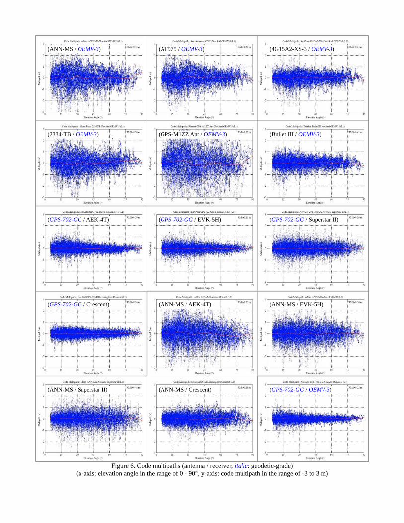
Figure 6. Code multipaths (antenna / receiver, italic: geodetic-grade)(x-axis: elevation angle in the range of 0 - 90°, y-axis: code multipath in the range of -3 to 3 m)
(ANN-MS / OEMV-3) (AT575 / OEMV-3) (4G15A2-XS-3 / OEMV-3)
(2334-TB / OEMV-3) (GPS-M1ZZ Ant / OEMV-3) (Bullet III / OEMV-3)
(GPS-702-GG / AEK-4T) (GPS-702-GG / EVK-5H) (GPS-702-GG / Superstar II)
(GPS-702-GG / Crescent) (ANN-MS / AEK-4T) (ANN-MS / EVK-5H)
(ANN-MS / Superstar II) (ANN-MS / Crescent) (GPS-702-GG / OEMV-3)

Figure 7. Time series of RTK-GPS positioning errors (antenna / receiver, italic: geodetic-grade) (x-axis: time in the range of0 - 24 hr, y-axes: east/north/up errors in the range of -0.2 to 0.2 m, green: fixed solutions, orange: float solutions)
(ANN-MS / OEMV-3) (AT575 / OEMV-3) (4G15A2-XS-3 / OEMV-3)
(2334-TB / OEMV-3) (GPS-M1ZZ Ant / OEMV-3) (Bullet III / OEMV-3)
(GPS-702-GG / AEK-4T) (GPS-702-GG / EVK-5H) (GPS-702-GG / Superstar II)
(GPS-702-GG / Crescent) (ANN-MS / AEK-4T) (ANN-MS / EVK-5H)
(ANN-MS / Superstar II) (ANN-MS / Crescent) (GPS-702-GG / OEMV-3)

Figure 8. TTFF with ambiguity resolution of RTK-GPS (antenna / receiver, italic : geodetic-grade) (x-axis: time in the rangeof 0 - 1800 s, blue bar: number of samples, red line: cumulative distribution in the range of 0 - 100 %)
(ANN-MS / OEMV-3) (AT575 / OEMV-3) (4G15A2-XS-3 / OEMV-3)
(2334-TB / OEMV-3) (GPS-M1ZZ Ant / OEMV-3) (Bullet III / OEMV-3)
(GPS-702-GG / AEK-4T) (GPS-702-GG / EVK-5H) (GPS-702-GG / Superstar II)
(GPS-702-GG / Crescent) (ANN-MS / AEK-4T) (ANN-MS / EVK-5H)
(ANN-MS / Superstar II) (ANN-MS / Crescent) (GPS-702-GG / OEMV-3)