evaluation of stainless steel fasteners …docs.trb.org/prp/17-03530.pdfwilliams, xia, darby, and...
TRANSCRIPT
Williams, Xia, Darby, and Sharp 1
EVALUATION OF STAINLESS STEEL FASTENERS FOR BOLTED FIELD SPLICE 1
CONNECTIONS OF ASTM A1010 CORROSION-RESISTANT STEEL PLATE 2
GIRDERS 3
4
5
6
Thomas R. Williams 7 University of Virginia 8
Thornton Hall B228, 351 McCormick Road, Charlottesville, VA 22903 9
Tel: 434-293-1913; Fax: 434-293-1990; Email: [email protected] 10
11
Xuemeng Xia 12 University of Virginia 13
Wilsdorf Hall B20, McCormick Road, Charlottesville, VA 22903 14
Tel: 434-924-9436; Fax: 434-293-1990; Email: [email protected] 15
16
Thomas E. Darby III, P.E. 17 Virginia Department of Transportation 18
6200 Elko Tract Road, Sandston, VA 23150 19
Tel: 804-328-3166; Fax: 804-328-3136; Email: [email protected] 20
21
Stephen R. Sharp, Ph.D., P.E., Corresponding Author 22 Virginia Transportation Research Council 23
530 Edgemont Road, Charlottesville, VA 22903 24
Tel: 434-293-1913; Fax: 434-293-1990; Email: [email protected] 25
26
27
Word count: 5205 words text + 9 tables/figures x 250 words (each) = 7,455 words 28 29
30
31
32
33
34 Submission Date: November 15, 2016 35
Williams, Xia, Darby, and Sharp 2
ABSTRACT 1 The Virginia Department of Transportation initiated this study to compare the mechanical 2
properties, availability, and costs of stainless steel fastener materials for use with ASTM A1010 3
stainless steel plate. The investigation focused on fastener materials included in ASTM A193 4
and compared them to ASTM A325 bolts. The ASTM A193 bolts tested were the B6, B8, and 5
B8M. 6
Test results indicated that the ASTM A193 B8 fasteners provided the most economic 7
combination of mechanical strength, corrosion resistance, and cost. Uniaxial tension tests and 8
Skidmore-Wilhelm rotational capacity tests revealed that the A193 B6 fasteners had high 9
strength but lower ductility whereas the ASTM A193 B8M fasteners had lower strength but 10
higher ductility. The ASTM A193 B8 fastener had an ideal combination of strength and 11
ductility. The mechanical performance of the ASTM A193 fasteners was further improved by 12
the use of hardened washers. Because the bolts are hot forged, sensitization, which can reduce 13
corrosion resistance, was of concern. Standard testing indicated that the B8 and B8M as-14
received bolts were unsensitized. 15
The cost of ASTM A193 B8 fasteners compared favorably with that of other stainless 16
steel fasteners, and the B8 fasteners are available from manufacturers complying with Buy 17
America requirements. Although the cost of stainless steel fasteners are higher than of ASTM 18
A325 steel fasteners, larger orders as usage increases may help reduce prices. The initial 19
research indicates that stainless fasteners can be a structurally sound option for building reduced 20
maintenance bridges. 21
22
Keywords: ASTM A1010, ASTM A193, ASTM A194, Buy America, plate girder, bolt tension, 23
corrosion, rotational capacity, slip-critical, splice plate connection, stainless steel 24
25
Williams, Xia, Darby, and Sharp 3
INTRODUCTION 1 After World War II, the standard practice in the United States with regard to steel bridge 2
members was to specify the use of ASTM A36 steel with multiple coats of lead-based paint for 3
protection against corrosion. Weathering steel was developed in other industries and adapted to 4
bridge use in accordance with ASTM A709. Weathering steel did not require coating and was 5
believed to add life-cycle cost savings by also avoiding periodic recoating in-service. After 6
limitations with weathering steel were discovered, the FHWA issued a list of contributing factors 7
identifying conditions that should be avoided (1). The use of ASTM A1010 (A1010) steel 8
girders in bridges may provide the combination of corrosion resistance and life-cycle cost 9
savings to address those factors. 10
Several years ago, Fletcher performed a study to compare the corrosion resistance of 11
several steel plate products (2). This study showed that based on life-cycle analysis, the A1010 12
steel plate material had a 90% chance of being more economical than conventional coated steel 13
after 20 years of service and a 100% chance after 40 years of service (2). The savings resulted 14
from the corrosion resistance of the steel, which makes painting and other corrosion-related 15
maintenance unnecessary. 16
In 2004, as part of the Innovative Bridge Research and Construction Program, a multi-17
cell box girder bridge design in Williams, California, used A1010 steel because of the close 18
proximity to water beneath the bridge. An A1010 steel producer used the material to fabricate 19
the first plate girders to support a bridge at their Coatesville Steel Mill in Pennsylvania in 2007. 20
Although these efforts demonstrate the viability of this technology, the Oregon Department of 21
Transportation is particularly notable in their efforts to use A1010 steel as a more corrosion-22
resistant alternative to weathering steel (3). As a result of this work, several other highway 23
agencies are pursuing the use of A1010 steel plate girders. 24
The Virginia Department of Transportation (VDOT) has applications where corrosion-25
resistant steel plate girders would be a competitive solution compared with other materials. 26
However, unlike previously built bridges, the first VDOT A1010 steel plate girder bridge would 27
require the use of bolted splice plate connections. Therefore, with the improved corrosion-28
resistant properties of the A1010 steel plate girders, the type of steel fastener to be used required 29
careful consideration. 30
VDOT specifications require the use of high-strength (ASTM A325 (A325)) bolts. The 31
current specifications, however, do not recognize ASTM A193 fasteners. In addition, the design 32
specifications require bolted splices to meet strict slip-critical behavior limits in design and 33
construction, and field testing is one component. Faying surfaces must meet prescribed friction 34
requirements, and field-tightening requirements must provide the specified clamping force 35
tension. An additional challenge is that the fasteners must meet the Buy America (BA) 36
requirements (4). Therefore, the question arose as to which stainless steel fastener would 37
appropriately balance the requirements of mechanical strength, economy, and corrosion 38
resistance in the assembly of A1010 steel plate girders. 39
40
PURPOSE AND SCOPE 41 To support the maintenance-free properties of A1010 steel plate girders, it is desirable to use 42
corrosion-resistant fasteners at the girder connections. This study used laboratory testing to 43
investigate the feasibility of using stainless steel fasteners with A1010 steel plate girders and to 44
determine if a reliable turn-of-the-nut tightening procedure could be developed. The study 45

Williams, Xia, Darby, and Sharp 4
assessed mechanical properties, corrosion resistance, shipping time, cost, and material 1
availability in accordance with BA requirements. 2
Bolt installation acceptance criteria were then developed around the splice plate design 3
for the replacement of the Route 340 Bridge over the South River in Waynesboro, Virginia. This 4
information provided appropriate information needed for selecting a fastener and determining the 5
turn-of-nut tightening procedure for splicing A1010 steel plate girders. 6
7
METHODS 8 9
Literature Review 10 The researchers reviewed current specifications regarding stainless steel bolting and bridge 11
construction to determine the material options available for testing. The literature included 12
ASTM, VDOT, and FHWA standards. 13
14
Selection and Ordering of Materials 15 Existing VDOT specifications allow the use of high-strength A325 bolts and matching nuts and 16
washer material (5). A325 bolts were tested alongside the stainless fastener assemblies for the 17
purpose of comparison (Table 1). ASTM A193 (A193) bolts manufactured from stainless steel 18
alloys were known to approach the VDOT specified strength for high-strength bolts. 19
20 TABLE 1 Matching ASTM and SAE Stainless Steel Material Types 21 Assembly
ID
Quantity
ASTM Bolt Designation
(SAE Bolt Designation)
ASTM Nut Designation
(SAE Bolt Designation)
Washer
B6 20 A193 B6 (Type 410) A194 Grade 6 (Type 410) SAE 410
B8 20 A193 B8 Class 2 (Type 304) A194 Grade 8 (Type 304) SAE 304
B8M 20 A193 B8M Class 2 (Type 316) A194 Grade 8M (Type 316) SAE 316
A325
Uncoated
20 A325 Type I Plain A563 Grade DH Plain, ASTM F436
A325
Galvanized
20 A325 Type I Galvanized A563 Galvanized, Grade
DH
Galvanized, ASTM
F436
22 The primary experimental concern with the A193 bolts was their ability to achieve 23
adequate mechanical properties. The fasteners selected would provide an alternative to standard 24
steel fasteners and needed to achieve the necessary clamping force with standard installation 25
methods. 26
Although mechanical properties are critical, A193 fasteners are produced to meet high 27
temperature service applications needed in the mechanical engineering field, but BA 28
requirements are not an industry issue in many of these applications (6). However, for federally 29
funded highway programs, BA requirements guide the procurement process for locating potential 30
suppliers and placing orders for steel and iron goods (4). Therefore, this study needed to confirm 31
procurement of fasteners complied with the BA requirements. To assess costs, the initial order 32
provided the values for the cost comparison. In addition, the researchers recorded the delivery 33
times of the initial and subsequent fastener orders. 34
Finally, since minimizing maintenance is important, the long-term durability of the 35
fasteners is critical. The inherent corrosion properties of the A193 bolts in comparison to A1010 36
was not of concern since the A193 bolts contain more chromium than A1010, making them more 37
corrosion resistant. However, for the manufacturing of B8 and B8M Class 2 bolts, it is common 38
in the United States to hot forge. The bolt head is placed on a threaded rod by heating the rod 39

Williams, Xia, Darby, and Sharp 5
red hot and forming the hex head. This can potentially lead to the release of tension that 1
occurred during strain hardening and a phenomenon called sensitization to occur (7). 2
Sensitization refers to the migration of chromium from the center of the grain to the grain 3
boundaries to bind with carbon to form chromium carbides because of improper heating and 4
cooling. This migration of chromium causes the material to become susceptible to intergranular 5
corrosion, which becomes a problem following installation and cause premature bolt failure. 6
7
Design of Route 340 Bridge 8 The bridge replacement project in Waynesboro was designed to allow for the use of 7/8-inch 9
stainless steel fasteners with a minimum tensile strength of 100 ksi at the splices. The design 10
followed AASHTO design guidelines and incorporated factors such as the number of slip planes, 11
surface condition factor, and hole size factor. Based on this analysis, a required minimum bolt 12
tension of 30 kips per bolt was used, rather than the conventional minimum bolt tension of 39 13
kips for a 7/8-inch A325 bolt, to determine if the fasteners were acceptable and would provide 14
the clamping load needed for a splice plate connection. 15
16
Testing 17 Uniaxial Tension Testing 18
Tension testing of the full-size fasteners in accordance with ASTM A370 determined ultimate 19
strength values and the elongation at failure (8). 3 ½ inch bolts were used for testing with the 20
distance between the grip length varying, with the variability in length being approximately 1 – 3 21
threads exposed above the lower grip. The data from the tension testing provided force-22
displacement graphs that illustrated the strength and ductility properties of each fastener type. A 23
laser extensometer measured the bolt elongation as the bolt was pulled in a tension frame. 24
25
Incremental Rotation Testing 26
VDOT’s Road and Bridge Specifications, Section 226.02(h), specify high-strength fastener A325 27
shall meet Rotational Capacity testing, and provides requirements for minimum tension, rotation 28
and maximum torque (5). This test was used on our control group of A325 fasteners and was the 29
basis for developing the incremental rotation test used to study the stainless alloys of A193 30
fasteners. 31
After receiving the fasteners, researchers grouped together fastener assemblies for testing, 32
clearly labeling each assembly to facilitate date recording. To study the rotation-tension 33
relationship in the sample fasteners, a fastener assembly was placed in the Skidmore-Wilhelm 34
device adding enough washers to leave one or two threads sticking out beyond the face of the 35
nut. A pea sized amount of anti-seizing lubricant was applied to the threads before placing the 36
nut at the end followed by tightening the nut to a tension of 4 kips (an industry standard for 7/8 37
inch diameter high-strength fasteners). A reference mark at zero and additional marks at twenty 38
degree increments were made from this position of the nut before turning the nut in the test. 39
The nut was turned twenty degrees and the tension and torque (using a dial type torque 40
wrench) were recorded. This process continued until the nut was turned sufficiently beyond 41
what would be allowed during field installation. 42
To analyze the data, the tension and the torque was plotted against the rotation for each 43
sample lot and these graphs analyzed to determine where the relationships exhibited non-linear 44
plastic behavior. It is difficult to determine an analytical basis because the bolt is under 45
combined tension and shear (torsion) stress, but the torque is resisted by both the bolt and the nut 46

Williams, Xia, Darby, and Sharp 6
at the interface with the washer. For this reason, the researchers decided to rely on the empirical 1
results to affirm the design values were safe. 2
After the first batch of tests, the researchers formalized the testing procedure by writing 3
an acceptance test using specific rotational capacity requirements for the A193 fastener 4
assemblies. The requirements were based on the test results of the first batch of A193 fastener 5
assemblies. The tension and torque requirements were adjusted to account for the different 6
properties of the A193 fasteners as compared with the A325 fasteners. The revised procedure 7
was used for the testing of subsequent bolt batches. 8
9 Hardness Testing 10
11 Rockwell Hardness Testing Rockwell B hardness testing was performed in accordance with 12
ASTM E18 (10). Rockwell hardness testing of the tested nuts was performed at 12 points, at 13
each corner, and at the midpoint between corners. Hardness testing was performed on untested 14
washers at 12 locations, 3 in each cardinal direction, when permissible. 15
A tested B8 bolt was cut longitudinally into three pieces. The samples were polished to a 16
final polish of 1200 grit in accordance with ASTM E3 (9). Hardness tests were then performed 17
down the length of the bolt. 18
19
Vickers Hardness Testing Bolts were cut in the same way as with the tested B8 bolt. The 20
samples were polished to 1200 grit in accordance with ASTM E3 (9). Microhardness tests were 21
performed using the Buehler Micromet 5101 hardness tester with a load of 1 kilogram and a 22
distance of 0.05 inch between data points across the diameter of the bolt. The testing was done 23
in accordance with ASTM E384 (11). The data were reported as the average of the three middle 24
points. 25
26
Optical Microscopy 27
The optical images of the bolt threads were taken on an as-received bolt with the Hirox KH-7700 28
Macro Lens with standard settings and lighting. The microscopy images of the sectioned bolt 29
threads were polished to a 3-micron finish in accordance with ASTM E3 (9). The images were 30
then taken at 100x magnification. 31
32
Scanning Electron Microscopy 33
The bolt fracture samples were first cut to fit inside the scanning electron microscope chamber 34
and then sonicated in ethanol for 5 minutes to remove any remaining stainless steel anti-seize 35
compound that remained on the samples from previous testing. All images were taken in the 36
secondary electron mode. 37
38
Sensitization Testing of B8 and B8M Bolts for Corrosion Resistance 39
The bolts were cut longitudinally into three pieces. These samples were then prepared and tested 40
in accordance with ASTM A262 (12). A second set of samples was prepared with a final polish 41
using a 3-micron diamond polish. All images were taken on the Hirox KH-7700 using the 10C 42
lens with a magnification of 490x unless otherwise specified. 43
The B8 and B8M bolt head samples were polished to 3 microns both to remove the 44
previous etching and to provide a clean surface to sensitize. The two bolt heads were then cut in 45
half. One-half of each bolt head was heated to 675°C (1247°F) in a furnace for 1 hour as guided 46

Williams, Xia, Darby, and Sharp 7
by ASTM A262 (12). Each sample was allowed to cool to room temperature in the closed 1
furnace environment. The samples were etched in accordance with ASTM A262 (12). 2
3
RESULTS AND DISCUSSION 4
5
Selection and Ordering of Materials 6 To assess costs, an initial order included several bolt options. The B6 bolt assembly order 7
included 20 A193 bolts; 20 ASTM A194 (A194) Grade 6 nuts; and 40 SAE Type 410 washers. 8
The B8 bolt assembly order included 30 A193 bolts; 30 A194 Grade 6 nuts; and 60 SAE Type 9
304 washers. The B8M bolt assembly order included 20 A193 bolts; 20 A194 Grade 6 nuts; and 10
40 SAE Type 316 washers. Galvanized and uncoated A325 bolt assemblies meeting the VDOT 11
specification were also ordered to serve as a baseline for comparison during testing. All items 12
discussed in this report met BA requirements; a fourth type of bolt was not included in this study 13
because a supplier that met the BA requirements for A193 B8MN bolts could not be located. 14
Therefore, it is important to know that not all A193 bolts will meet BA requirements. 15
The cost breakdown of each stainless fastener assembly is provided in Table 2. Although 16
it is possible that the price per item was affected by the relatively small quantities of material 17
purchased, it was surprising how substantial the difference in cost was between the B6 and the 18
other fasteners. Earlier work has shown the sensitivity of stainless pricing to alloying elements 19
such as nickel and molybdenum, so it might be expected that the B6 bolt would have a lower 20
cost compared to the B8 and B8M fasteners (13). It was also interesting that the cost of the 21
A193 bolts was around the same order of magnitude, but the cost of the nut and washer for the 22
B6 fasteners was much higher. 23
24 TABLE 2 Costs for Each Stainless Steel Fastener Assemblies Item Listed 25 Item (Dimensions) A325 Uncoated B6 B8 B8M
Bolt (⅞-in x3-½ in ) $1.88 $28.25 $14.65 $14.50
Nut (for ⅞-in bolt) $1.90 $131.00 $16.50 $17.80
Washer (for ⅞-in bolt) $0.31 $130.00 $2.60 $1.90
Total Stainless Steel Fastener Assembly:
1 Bolt, 1 Nut, and 1 Washer $4.09 $289.25 $33.75 $34.20
26
The delivery times for various vendors were also tracked and compared for the initial and 27
subsequent orders. Vendor 1 provided 7/8-inch A325 assemblies, both plain and galvanized, in 6 28
days, which was used as a baseline to evaluate the delivery of the other stainless steel nut, bolt, 29
washer assemblies. Vendor 2 provided 7/8-inch and 1-inch A193 bolts and A194 nuts in 7 days. 30
Vendor 3 provided 7/8-inch 303 stainless steel washers in 5 days. Vendor 3 provided 7/8-inch 31
304 stainless steel washers in 16 days. The first three vendors had reasonably close delivery 32
times as compared to those for an A325 assembly. Vendor 4 required nearly 3 times as long to 33
provide the stainless product when compared to the delivery time for A325 fasteners. Moreover, 34
a second order placed with Vendor 2 for stainless fasteners required 45 days from the time the 35
order was place until it was delivered. It is clear that additional time can be required to receive 36
A193 and A194 stainless fasteners. 37
38
Test Results 39
40 Uniaxial Tension Behavior of Fastener Assemblies 41
Williams, Xia, Darby, and Sharp 8
The A193 standard required the 7/8-inch-diameter stainless fasteners to reach an ultimate 1
strength of up to 115 ksi (6). Figure 1(a) shows the average test results for the uniaxial tension 2
tests of three bolts (7/8-inch diameter, 3.5-inch length) from each of the three stainless fastener 3
types. Each fastener type reached its required strength. The B8M fastener showed the most 4
ductility, and the B6 fasteners the least. The B8 fastener had a combination of high strength and 5
ductility. 6
There were difficulties with the uniaxial tension tests concerning equipment. A laser 7
extensometer recorded the elongation of the bolt in the tension frame. At low elongation and 8
stress values, there were inconsistencies in the test data, which was attributed to the sensitivity of 9
the laser. However, as the displacement value became significant, the inconsistencies stopped. 10

Williams, Xia, Darby, and Sharp 9
1 FIGURE 1 Stress vs. displacement curves showing (a) average response for A193 B8, B8M and B6 stainless 2 fastener assemblies, and (b) graph of variability in uniaxial tension testing for different A193 B8 fasteners, 3 with each line representing results from A193 B fastener testing. 4 5
(a)
(b)

Williams, Xia, Darby, and Sharp 10
A193 B8 Fastener Uniaxial Test Variability The A193 B8 fasteners appeared to show limited 1
variability in the uniaxial tension tests and rotational capacity tests. Figure 1(b) compares the 2
uniaxial test results of three individual A193 B8 fasteners with the overall average. The figure 3
compares only stresses above 90 ksi because of measuring inconsistencies at low displacement 4
values. The solid line represents the average, and the dashed lines represent individual fasteners. 5
Near yielding, the fastener stresses range from approximately 110 ksi to more than 120 ksi. The 6
ultimate strength range generally was between 135 ksi and 140 ksi. 7 8 Incremental Rotation Testing 9
Researchers conducted initial rotational capacity tests on a single batch of stainless steel 10
fasteners and compared the results with those of control tests of A325 fasteners. The stainless 11
steel fasteners tested were as follows: eight B8 assemblies, seven B8M assemblies, seven B6 12
assemblies, eight plain A325 assemblies, and five galvanized A325 assemblies. 13
During initial testing of A193 bolts, after the A325 bolts were tested to develop a baseline 14
for comparison, researchers used a stainless alloy washer that was not specified as a hardened 15
washer. The recorded torques were higher than anticipated, and the cause was the developed 16
friction as the nut ground into the washer. The subsequent distress in the washer was clearly 17
visible without magnification. Soon after these first few bolts were tested, hardened stainless 18
steel washers were obtained for the remaining testing which eliminated this problem and 19
demonstrated that hardened washers must be used. 20
Results were plotted each day after testing using the rotation of the nut as the independent 21
variable and the tension and torques as the dependent variables. The trend indicated on the 22
graphs was studied for consistency to support the validity of the testing method. Researchers 23
expected to note a portion of the graph indicating plasticity since earlier direct tension testing 24
showed a yield point in that mechanism. The levels of stress and rotation necessary to achieve 25
that stress were noted. Next, the amount of rotation beyond the “break point” in the linearity of 26
the graph was noted to ensure the bolts would have reserve strength beyond the installation point. 27
The trend toward the end of the graph was observed to determine if there was a distinct loss of 28
load-carrying capacity prior to failure. Finally, the rotation vs. torque curves were studied to 29
ensure that something unforeseen or unanticipated had not occurred that would be considered 30
detrimental to the long-term load-carrying capacity of the bolt, such as unexplained spikes in the 31
torque during tightening. 32
Figure 2(a) shows the average results of the initial rotational capacity tests. The figure 33
shows the development of tension in the bolted assemblies as the angle of rotation of the nut was 34
increased. The angle of rotation was measured relative to the snug tight condition at 0 degrees. 35
In general, the stainless steel fastener assemblies had lower tension values than the plain steel 36
assemblies at high angles of rotation. The line shows the average data from the A325 uncoated 37
assemblies, serving as a basis for comparison. The relationship between the two material types 38
was not as clear at lower angles of rotation. The B6 and B8 assemblies appeared to develop the 39
highest tension values up to about 150 degrees of rotation. The tension in the A325 galvanized 40
and uncoated assemblies significantly increased between about 125 and 250 degrees. Among the 41
stainless fastener assemblies, the B6 assembly appeared to reach the highest overall tension, 42
followed closely by the B8 assembly. Skidmore-Wilhelm testing showed that the B8 and B8M 43
assemblies were capable of reaching high angles of rotation. 44
The amount of torque required for the B6 and B8 assemblies to reach a given angle of 45
rotation was greater than for the A325 uncoated assembly, as shown by Figure 2(b). Despite 46
this, the stainless assemblies all remained below the current torque limit set by VDOT. 47
Williams, Xia, Darby, and Sharp 11
Researchers gathered the data shown in the figure using a wall-mounted Skidmore-Wilhelm 1
testing device with the aid of a torque multiplier. Over the course of testing, the researchers also 2
used a free-standing Skidmore-Wilhelm test setup. The torque values recorded during testing 3
with the free-standing setup appeared to be consistently higher for all fastener materials than 4
when the wall-mounted device was used. This was attributed to using a torque multiplier for the 5
wall-mounted device which reduced the leverage required while gathering data from the torque 6
wrench. 7
8

Williams, Xia, Darby, and Sharp 12
1 FIGURE 2 Rotational capacity test results showing (a) the tension vs. angle of rotation for fastener 2 assemblies, and (b) the torque vs. angle of rotation for fastener assemblies. Galv. = galvanized. 3 4
Bolt tension did not develop as rapidly in the A193 bolts as it did in the standard A325 5
bolts. However, the A193 bolts reliably attained the 30 kips per bolt assumed in the design. The 6
rotation required to attain the 30 kips was not a concern when compared to the amount of 7
rotation the bolts were able to undergo without fracturing. Because of the expense of obtaining 8
another Skidmore-Wilhelm testing device, the nuts were not turned enough to cause the bolt to 9
(a)
(b)
0
10
20
30
40
50
60
0 100 200 300 400 500 600
Ten
sio
n,
kip
Angle of Rotation, Degrees
B8 B6 B8M 325 Plain 325 Galv. 325 Trendline
0
100
200
300
400
500
600
700
0 100 200 300 400 500 600
To
rque,
ft*
lb
Angle of Rotation, Degrees
B6 B8 B8M B8 Hybrid 325 Plain 325 Galv.

Williams, Xia, Darby, and Sharp 13
fracture, which could have damaged the testing equipment. Instead, the nuts were turned well 1
beyond twice the angle of rotation anticipated to be used during installation. 2
The researchers often noted cracks developed in the root of the thread, as anticipated. In 3
addition, the researchers often noted a second zone just under the head of the bolt where necking 4
was beginning to occur. Discussions with workers at the manufacturing facility indicated that 5
these bolts are often manufactured by heating the round stock to orange hot before forming the 6
head and allowing the bolt to cool. This is thought to relieve some stresses but also reduces the 7
yield point of the steel. Standard practice for A325 bolts uses a greater degree of cold working. 8
This second zone of necking is thought to contribute to the reduction in the linearity of the 9
rotation vs. tension relationship. 10
At the end of the testing program, the researchers were comfortable that the bolts would 11
reliably achieve the 30 kips necessary to support the assumptions used during design and that the 12
bolts would have plenty of reserve capacity to justify the rotations specified to obtain the 13
specified clamping force. However, the tests were conducted on a fairly limited number of bolts 14
from each specified alloy, and only two production lots of bolts were tested. To establish a 15
recommended value for lower clamping force AASHTO splice designs, a statistically significant 16
number of bolt lots will be required to establish a design table. 17
A193 B8 Fastener Tension Variability Figure 3(Left) shows the variability of tension during 18
the tightening of the initial eight A193 B8 fasteners. Figure 3(Right) shows the tension 19
variability of eight A325 plain fasteners. The A325 fasteners showed significantly more 20
variability in tension between about 100 to 250 degrees of rotation from the “snug tight 21
condition.” 22
23
24 25 FIGURE 3 Comparison of variability in tension development in (Left) A193 B8 fastener, and (Right) A325 26 plain fastener. 27 28 All fasteners showed significant torque variability during testing. In general, the A325 29
fasteners required less torque than the A193 fasteners to reach a given angle of rotation, which 30
might in the stainless steel be attributed to thread galling (14). For any fastener type, torque at a 31
given angle of rotation could vary by as much as 100 ft-lb between fasteners of the same 32
production lot. 33
34
Hardness 35
0
10
20
30
40
50
60
70
0 100 200 300 400
Ten
sio
n i
n k
ip
Angle of Rotation, Degrees
0
10
20
30
40
50
60
70
0 100 200 300 400
Ten
sio
n i
n k
ip
Angle of Rotation, Degrees

Williams, Xia, Darby, and Sharp 14
In the standard carbon steel nut, washer, and bolt set, the nut was significantly less hard than the 1
washer. However, in the case of the stainless steel fasteners, the opposite was true. The washers 2
were significantly less hard than the nuts. This resulted in gouges being formed in the washers 3
during initial testing, which means that not all of the torque applied to the nut is used to tighten 4
the nut on the washer. Thus, to minimize the galling phenomenon, the hardness of the washer 5
should be maximized, while still meeting the necessary standards. 6
The B6 bolt showed the most consistent hardness through the length of the bolt. The 7
hardness values of the B8 and B8M bolts, however, varied greatly from the bolt head to the bolt 8
threads. The bolt head (Point 1) was at least 100 HV10 less than the threads (the last two points) 9
were ultimately. The greatest variability was in the bolt shank and the beginning of the threads, 10
most likely because of the manufacturing process. 11
A difference can be seen in the hardness values in the first and second sets of B8 bolts. 12
In the first, the B8 bolts tended to break just below the shank region; in the second, the B8 bolts 13
broke further down in the thread region. The locations of the fractures correlated with the drops 14
in hardness shown in Figure 4. The hardness values of the first set of B8 bolts dropped 15
significantly at Point 4, which is just below the heat mark on the bolt. The hardness values of the 16
second set dropped slightly at Point 5, which is about midway into the threads. These two drops 17
were also seen in the hardness testing of the tested B8 bolt. 18 19
20 FIGURE 4 Vickers microhardness values along bolt length. 21 22 Optical Microscopy 23
Figure 5(a) depicts the typical rough threads that can occur in the bolt manufacturing process. It 24
was determined that the metal smearing effect was due to a machining error as opposed to 25
microcracking that occurred on the surface. Figures 5(b) and 5(c) support the idea that the 26
material in the bolt threads was merely smeared as opposed to cracked. The rough threads did 27
not have an effect on the ability of the bolts to perform as needed. 28

Williams, Xia, Darby, and Sharp 15
1 FIGURE 5 Thread condition showing (a) rough threads on B6 bolt, (b) rough threads looking 2 perpendicularly at longitudinally cut B6 bolt, and (c) smooth threads looking perpendicularly at 3 longitudinally cut B8M bolt. 4 5
Scanning Electron Microscopy 6
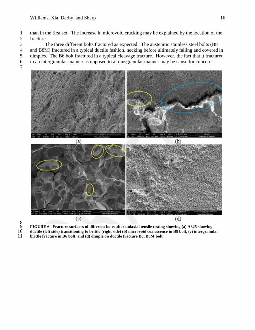
Figure 6(b) shows the two phases of microvoid coalescence cracking. As a ductile material is 7
being tensioned, microvoids begin forming. As more tension is placed on the sample, the 8
microvoids coalesce and form the structure in the region highlighted by the smaller oval. 9
Finally, the microvoids form into a crack, as shown by the region highlighted by the larger oval. 10
Microvoid coalescence cracking is most often seen in ductile fractures, such as that of the B8 11
bolt. The smooth “rock candy” structures that dominate in Figure 6(c) are indicative of an 12
intergranular cleavage fracture. However, the rough surfaces, highlighted by the ovals, show 13
regions of dimpling, which are indicative of some, though minimal, ductility in the material. 14
Figure 6(d) depicts dimples on the B8M fracture surface, which are indicative of a ductile 15
fracture. However, the B8M bolt (Figure 6d) did not show any signs of microvoid cracking on 16
the fracture surface. 17
A second set of B8 bolts was ordered and tested. These bolts also broke in a ductile 18
fashion. However, the fracture occurred lower in the threads and had more microvoid cracking 19
(a)
(b) (c)
Williams, Xia, Darby, and Sharp 16
than in the first set. The increase in microvoid cracking may be explained by the location of the 1
fracture. 2
The three different bolts fractured as expected. The austenitic stainless steel bolts (B8 3
and B8M) fractured in a typical ductile fashion, necking before ultimately failing and covered in 4
dimples. The B6 bolt fractured in a typical cleavage fracture. However, the fact that it fractured 5
in an intergranular manner as opposed to a transgranular manner may be cause for concern. 6 7
8 FIGURE 6 Fracture surfaces of different bolts after uniaxial tensile testing showing (a) A325 showing 9 ductile (left side) transitioning to brittle (right side) (b) microvoid coalescence in B8 bolt, (c) intergranular 10 brittle fracture in B6 bolt, and (d) dimple on ductile fracture B8, B8M bolt. 11

Williams, Xia, Darby, and Sharp 17
Sensitization of B8 and B8M Bolts 1
The B8 and B8M microstructures were evaluated in accordance with ASTM A262. However, 2
because scratches obscured the surface, the decision was made to polish the sample to 3 microns. 3
Figure 7(a) shows the B8 bolt head microstructure, where sensitization due to the manufacturing 4
process is most likely to occur. Although some ditch structures can be seen in the grains 5
highlighted by the ovals, grains are not completely surrounded by ditches. The streaks that are 6
seen across the image are forge lines that appeared only after electroetching. Neither the sample 7
prepared in accordance with ASTM A262 nor that was polished to 3 microns showed 8
sensitization. The as-received B8M bolt did not show any signs of sensitization. 9
A section of the B8 bolt was then intentionally sensitized and compared to an as-received 10
section. Figure 7(b) shows the unsensitized material on the left and the sensitized material on the 11
right in this photograph. The difference between the grain boundaries of the two can be easily 12
seen with grains on the sensitized bolt showing grains that are completely surrounded by ditches. 13
The as-received B8M bolt that received a similar additional heat treatment as the B8 did not 14
show any signs of sensitization. 15
16

Williams, Xia, Darby, and Sharp 18
1 FIGURE 7 Sensitization of (a) B8 bolt head region polished to 3 microns, and (b) comparison of B8 bolt head 2 after sensitization treatment on bolt section (unsensitized on left side of vertical black line and sensitized on 3 right side) at 210x magnification. 4
5
CONCLUSIONS 6
● The A193 stainless fasteners will develop lower tension values than traditional A325 7
steel fasteners at equivalent installation rotations. 8
● The A193 B8 fasteners tested met the minimum bolt splice tension requirement of 30 9
kips per bolt. 10
● The use of hardened washers helps achieve better mechanical performance. 11
(a)
(b)

Williams, Xia, Darby, and Sharp 19
● Bolt installation should be guided by rotation values rather than torque values. 1
● Not all A193 bolts or A194 nuts will meet BA requirements. 2
● Compared to A325 fasteners, additional delivery time should be anticipated when 3
specifying A193 fasteners. 4
● Sensitization was not detected in the as-received B8 or B8M bolts. 5
● A193 B8 bolts can meet the Route 340 splice plate connection design requirements. 6
ACKNOWLEDGMENTS 7 Justin Ocel of FHWA , Hormoz Seradj of Oregon DOT, Andrew Zickler, Keith Harrop, William 8
Via Jr., Larry Lundy, Keith Williams, Trey Simpson, and Brian Simmons of VDOT, and Bill 9
Ordel and James Copeland of VTRC are recognized for their contributions. 10
11
REFERENCES 12 1. Willett, T. O. Uncoated Weathering Steel in Structures. Publication Technical Advisory 13
5140.22. FHWA, U.S. Department of Transportation, 1989. 14
https://www.fhwa.dot.gov/bridge/t514022.cfm. Accessed July 11, 2016. 15
2. Fletcher, F. B. Improved Corrosion-Resistant Steel for Highway Bridge Construction. 16
Publication FHWA-HRT-11-062. FHWA, U.S. Department of Transportation, 2011. 17
3. Hormoz, S. Oregon’s Experience with ASTM A1010. In TRB 94th Annual Meeting 18
Compendium of Papers, Transportation Research Board of the National Academies, 19
Washington, D.C., 2015. 20
4. FHWA. Construction Program Guide: Buy America, March 16, 2016. 21
https://www.fhwa.dot.gov/construction/cqit/buyam.cfm. Accessed Feb. 5, 2016. 22
5. Virginia Department of Transportation. 2007 Road and Bridge Specifications. Richmond, 23
2007. 24
6. ASTM International. ASTM A193/A193M-16 Standard Specification for Alloy-Steel and 25
Stainless Steel Bolting for High Temperature or High Pressure Service and Other Special 26
Purpose Applications. West Conshohocken, Pa., 2016. 27
7. Portland Bolt & Manufacturing Company. Ordering A193 Class 2 Bolts, January 25, 2011. 28
http://www.portlandbolt.com/technical/faqs/ordering-astm-a193-class-2-bolts/. Accessed 29
Feb. 23, 2016. 30
8. ASTM International. ASTM A370-16 Standard Test Methods and Definitions for Mechanical 31
Testing of Steel Products. West Conshohocken, Pa., 2016. 32
9. ASTM International. ASTM E3-11 Standard Test Methods for Rockwell Hardness of 33
Metallic Materials. West Conshohocken, Pa., 2011. 34
10. ASTM International. ASTM E18-16 Standard Guide for Preparation of Metallographic 35
Specimens. West Conshohocken, Pa., 2016. 36
11. ASTM International. ASTM E384-16 Standard Test Method for Knoop and Vickers 37
Hardness of Materials. West Conshohocken, Pa., 2016. 38
12. ASTM International. ASTM A262-15 Standard Practice for Detecting Susceptibility to 39
Intergranular Attack in Austenitic Stainless Steels. West Conshohocken, Pa., 2015. 40
13. Presuel-Moreno, F., J. R. Scully, and, S. R. Sharp. Identification of Commercially Available 41
Alloys for Corrosion-Resistant Metallic Reinforcement and Test Methods for Evaluating 42
Corrosion-Resistant Reinforcement. Publication VTRC 08-R21. Virginia Transportation 43
Research Council, Charlottesville, 2008. 44

Williams, Xia, Darby, and Sharp 20
14. Fastenal Company. Technical Reference Guide, September 13, 2005. 1
http://www.fastenal.com/content/documents/FastenalTechnicalReferenceGuide.pdf. 2
Accessed November 15, 2016. 3