evaluation of stretched wire measurement based on
TRANSCRIPT

EVALUATION OF STRETCHED WIRE MEASUREMENT BASED ON PHOTOGRAMMETRY IN THE CONTEXT OF
CERN
IWAA 2016 – ESRF – Grenoble – France
A. Behrens, D. Mergelkuhl, CERN, Geneva, Switzerland C. Vendeuvre, INSA, Strasbourg, France

Table of content
• Ecartometry for accelerator alignment • Photogrammetry for wire measurement? • Test bench • Real scale mock-up • Alternative approach • Conclusion
04.10.2016

Ecartometry for accelerator alignment
04.10.2016
• Radial offsets with respect to stretched wire
• Precision 0.05 mm within sliding window of 150 m
• Team of 2 persons: 500 m accelerator per day
– Time consuming, cost intensive
– Personnel in radioactive area
How can radial alignment be automated?
Wire of 120 m MB
MQ
Could photogrammetry be a solution?
04.10.2016
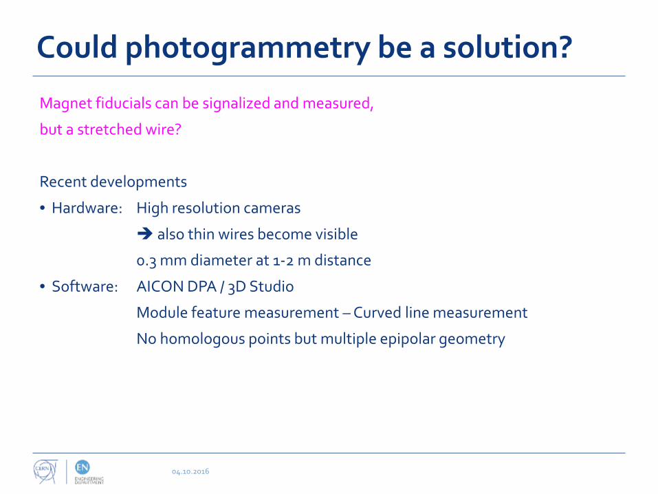
Magnet fiducials can be signalized and measured,
but a stretched wire?
Recent developments
• Hardware: High resolution cameras
also thin wires become visible
0.3 mm diameter at 1-2 m distance
• Software: AICON DPA / 3D Studio
Module feature measurement – Curved line measurement
No homologous points but multiple epipolar geometry

Test bench
04.10.2016
• Test bench used to define different parameters
• Afterwards precision and accuracy for wire measurement has been evaluated
• Steel grooves at each side
• 26 precise ceramic balls in contact
Up to 25 wires stretched between balls
• Photogrammetric sticker targets
• Metrology with precision of 2 µm
• Knowledge of wire position in horizontal,
NOT in vertical direction
Ceramic balls
Wires

Tested parameters ...
Wire
• Non-reflective
• Dark for good contrast
• Monofilament
• Non-metallic
• Of adapted size, wire should correspond to 1-2 pixel in image
black, monofilament fishing wire of 0.3 mm diameter
Software
• Edge method
• Spacing 0.25 mm – 2.0 mm
• Contrast values 20-40
04.10.2016
0
50
100
150
200
250
0 5 10 15 20 25 30 35 40
grey
val
ue
pixel
Grey value profile of "thick" line
0
50
100
150
200
250
0 5 10 15 20 25 30 35 40
grey
val
ue
pixel
Grey value profile of "thin" line
«Edge» method
«Centreline» method

... tested parameters
Camera
• Nikon D3x with 24 Megapixel
• AICON «metric» 28 mm lens
• ISO 100-600
• Exposure time 1/125 – 1/250 sec.
• Aperture 11 or 16
• Top mounted flash
Configuration
• 16 images at distance of ~1.4 m
• Intersection angles above 90 degree
04.10.2016
Image positions
Object points

How to analyze the measurement ?
04.10.2016
• 10 wires measured 10 times
• Horizontal 2D distances between 5 sticker targets and 10 wires
500 measurements for analysis
• Least squares fitted mean line of measured points
• Problems:
• Shadow
• Lines do not end
Iterative error detection


• LHC dipole mock-up in wooden tunnel
• 165 magnet fiducials and additional targets
• 3 wires
• Plumb line as 4th wire for definition of vertical
• 10 photogrammetric measurements
Real scale test
04.10.2016

Real scale test - Results
04.10.2016
• 3D coordinates of 165 targets
• 2D horizontal distances between 10 targets and 3 wires
σ (µm) min (µm) max (µm)
Wire 1 nylon 8.0 -29.4 28.9
Wire 2 vectran 6.3 -20.8 22.0 Wire 3 nylon 7.9 -24.4 26.3
Sigma of points X (µm) Y (µm) Z (µm) Precision AICON 4.2 7.7 4.2 Repeatability 4.0 7.0 4.3
Depth

Comparison to Wild T3000
04.10.2016
• Comparison to theodolite measurement
• 3D coordinates by intersection
• Precision 10-20µm
• Differences for 3D coordinates
• Wire by multiple plane intersection
• Differences for 2D distances
σ (µm) min (µm) max (µm) Quadratic mean 8.1 15.2 13.3
Wire 1 nylon
Wire 2 vectran
Wire 3 nylon
Quadratic mean 19.9 34.2 15.0

Alternative Approach
04.10.2016
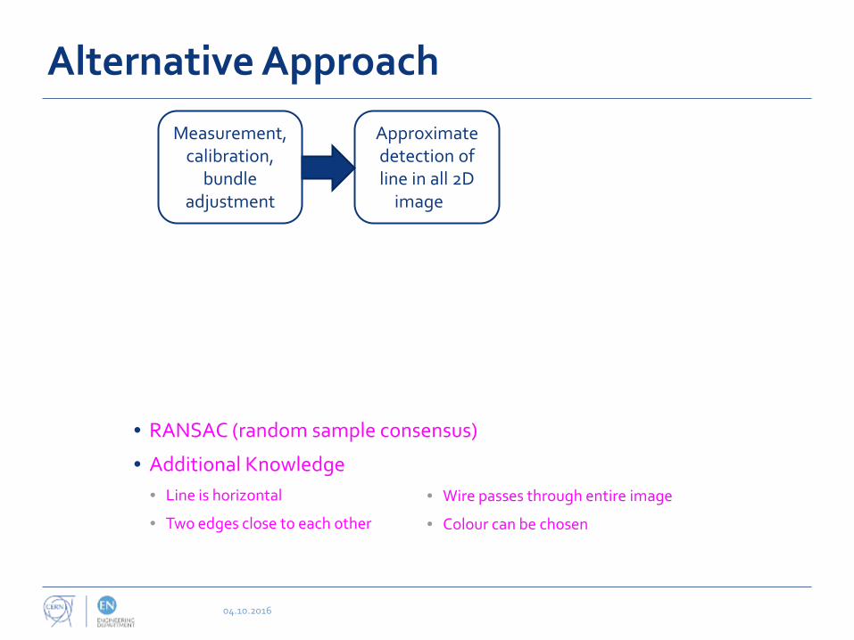
Measurement, calibration,
bundle adjustment
• Existing AICON Move Inspect for collimator train
Alternative Approach
04.10.2016
Approximate detection of line in all 2D
imageof
Measurement, calibration,
bundle adjustment
• RANSAC (random sample consensus)
• Additional Knowledge • Line is horizontal
• Two edges close to each other
• Wire passes through entire image
• Colour can be chosen

Alternative Approach
04.10.2016
Approximate detection of line in all 2D
imageof
Measurement of edge points
for each line
Measurement, calibration,
bundle adjustment
• Sub pixel edge detector Trujillo-Pino
• Iterative correction of distortion
• Edge points separated for both edges

Alternative Approach
04.10.2016
Approximate detection of line in all 2D
imageof
Measurement of edge points
for each line
Calculation of mean line in each image
Measurement, calibration,
bundle adjustment
• Mean line by linear regression for each edge
• Angle bisector corresponds to wire measurement in image

Alternative Approach
04.10.2016
Approximate detection of line in all 2D
imageof
Measurement of edge points
for each line
Calculation of mean line in each image
Transformation of lines from
image space to planes in object
space
Measurement, calibration,
bundle adjustment
• Intersection points of line with image borders projected in object space by collinearity equations

Alternative Approach
04.10.2016
Approximate detection of line in all 2D
imageof
Measurement of edge points
for each line
Calculation of mean line in each image
Intersection of multiple
planes in a line
Transformation of lines from
image space to planes in object
space
Measurement, calibration,
bundle adjustment
• Line calculated by individual adjustment or within bundle adjustment
Alternative approach - Results
04.10.2016
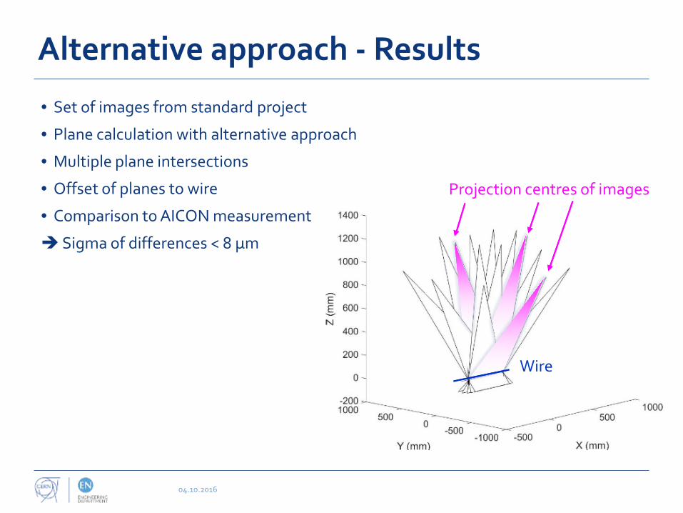
• Set of images from standard project
• Plane calculation with alternative approach
• Multiple plane intersections
• Offset of planes to wire
• Comparison to AICON measurement
Sigma of differences < 8 µm
Projection centres of images
Wire

Conclusion and outlook
04.10.2016
• Photogrammetry is possible tool for ecartometry
• Precision of distances between points and wire less than 10 µm
What comes next?
• Real scale comparison with Micro-triangulation as developed in the PACMAN project (see talk from V. Vlachakis Friday morning)
• Definition of scale
• Introduction of the vertical
• Measurement of complete wire / complete sector in manual mode
• Interesting approach during detector fiducialisation, for example wire chambers
• To be studied...

04.10.2016
Thank you!
Merci!