evaluation of subsurface engineered … · 2018-08-21 · evaluation of subsurface engineered...
TRANSCRIPT
xvEPA
United StatesEnvironmentalProtection Agency
Office of Solid Waste andEmergency Response(5102G)
EPA 542-R-98-005August 1998www.clu-in.com
Evaluation of SubsurfaceEngineered Barriersat Waste Sites
SDMS DocID 2072482
Do

TABLE 3-2MATRIX FOR EVALUATING BARRIER DESIGN AGAINST ACCEPTABLE INDUSTRY PRACTICES
CategoryHydrogeologic InvestigationFeasibility DeterminationGeotechnical Design Investigation
Borings along alignmentGeotech. physical testing
Barrier DesignGroundwater modelingAlignment & key depth+Wall thickness/hydrofractureTrench stability & analysisBackfill permeability
testing/optimizationTrench slurry compatibilityLong term backfill compatibilityBarrier penetration detailsCap/barrier interfaceProtection from dessicationProtection from surface loadingProtection from subsurface breachSediment & erosion control
Less than AcceptableNoneNone
1 boring/>200 ftNone
No Modeling<2ft<2ftNone
<3<3<3
NoneNone<1 ftNoneNoneNone
AcceptableYes*Yes"
1 boring/1 00-200 ft***Yes****
Feasibility Modeling2-4 ft Key
2-4 ftAnalytical
3 Tests3 Tests3 Tests
Contractor DesignedComponent Overlay
1-2 ft Clay CapSpanning ElementsPhysical Protection
Contractor Designed
Better than Acceptable>>
1 boring/<100ft>
Design Performance Modeling>4ft>4ft
Numerical
>3>3>3
Designer DesignedPhysical Connection
>2ft>>
Designer Designed
Documentation of hydrogeological investigation necessary to establish design parameters was available .The feasibility determination was based on adequate geological and hydrogeologic site data.Spacing of borings depends on geologic variability at the site
' Representative gradation, limits, unit weight and key permeability.Soil key shown. Rock key rated less than acceptable (to fractured bedrock-no grouting), acceptable (0.5-1.0 ft into sound rock)better than acceptable (more than 1 ft into sound rock).
20
1.1.1 Historical Development of Engineered Barriers
Historically, vertical barriers have been used on construction projects to prevent inflow ofgroundwater into deep excavations, as well as to support excavation. Sheet pile walls (first ofwood and later of steel) have been installed throughout the world for many decades. The 1950ssaw the development of slurry trenching technology, in which bentonite was used to support thesides of trenches under excavation before they were backfilled. That development took placeindependently in Europe and in the. United States.
A market existed in Europe for the construction of deep excavations in urban areas adjacent toexisting buildings, even historical structures. That demand created a need to developtechnologies for rigid support systems and for limiting the drawdown of the water table outsidethe excavation to minimize subsidence. Secant pile walls first were used after World War II;later, in the 1950s, concrete slurry wall technology was developed. That development was anatural evolution of the secant wall technology, with the goal of decreasing the number of jointsbetween piles, thereby minimizing the risk of blowouts in the mass excavation through faultyjoints. By the end of the 1960s, cement-bentonite cutoff wall technology also had beendeveloped in Europe to allow deep excavation below the groundwater table for power plants andlocks, or to act as a cutoff through pervious overburden soils on dam projects. In Europe to date,the use of cement-bentonite (quite often in conjunction with a geomembrane) remains thepreferred technique for seepage control, with applications including hazardous waste sites.
The development of slurry trenching technology in the United States, occurring independentlyfrom its development in Europe, took place in the late 1940s and early 1950s and was based onthe use of the soil-beritonite technique (still unused in Europe). The main goal was to prevent theflow of water into deep excavations for lock and dam projects, or to minimize seepage beneathand through dams and dikes. The first industrial application of the soil-bentonite technique tookplace in 1950 at the Terminal Island project in California. Slurry trenches then were usedextensively in the 1960s and 1970s for. dam projects as permanent cutoff walls and for theconstruction of the Tombigbee Waterway.
More recently, by the late 1970s and early 1980s, vertical engineered barriers have been used inthe United States to isolate hazardous wastes from groundwater, as slurry walls, primarilysoil-bentonite cutoffs, began to be used to contain hazardous wastes. Initially, the goal was tocontain contaminated groundwater for a "limited" period of time. A 30-year life span for thecontainment was often the objective. By the late 1980s, the concept of establishing a reversegradient appeared. In such applications, an extraction or pumping system is installed in thecontaminated zone, in addition to the peripheral cutoff wall. This approach allows maintenanceof an inward flow through the wall at a very low rate. This approach has its advantages, since itdecreases, if not eliminates, the risk arising from deficiency in design or installation or evenlocalized anomalies in the aquitard layer.
s.
In recent years, new concepts and developments in subsurface engineered systems have beenintroduced. Among them are:
• The funnel and gate, or permeable reactive wall: A contaminant plume is channeledbetween impervious vertical walls, referred to as the funnel, and flows naturally througha permeable reactive barrier gate, where the pollutants are treated in situ during the flowprocess.
• The use of slurry trenching technology to install a deep groundwater extraction trench,instead of an impervious cutoff wall: The slurry used to support the trench is made froma biodegradable material (instead of bentonite, which would reduce flow to the trench).After excavation, the trench is backfilled with a pervious material, and the slurry fillingthe voids of the pervious material biodegrades. Drains installed by this biopolymermethod typically are from 20 to 50 feet deep, and sometimes deeper.
Quite recently, engineers began to be concerned not only about the hydraulic transport ofcontaminants, but also about the diffusion of contaminants through vertical barriers, a chemicalprocess. This issue is crucial for the long term (usually considered to be well in excess of30 years), in terms of the integrity of vertical barriers. New technologies are emerging toincrease the sorption capacity of vertical barriers, primarily through the use of additives in thebackfill materials.
In addition, improvements in barrier construction technology allow the installation of verticalbarriers to depths as much as 400 feet, through various soil and rock conditions, and in hostileenvironments (such as brackish water and water contaminated with chemicals).
Caps have been used to prevent the downward flow of surface runoff and precipitation insidecontaminated sites. The concept is similar to the use of impervious blankets on the upstreamslope of a dam. At first, caps included clay blankets. The introduction of chemically resistantgeosynthetic materials that have minimal diffusive conductivity has significantly improved thequality and the ease of installation of caps. Caps have been used at sites as large as 400 acres.
1.1.2 Types of Engineered Barriers
Engineered barriers, as discussed in this report, are vertical barriers and caps. Appendix Aprovides details of the design, construction, and construction quality assurance (CQA) andconstruction quality control (CQC) for vertical barriers and caps. Significant features of verticalbarriers and caps are discussed below.
Note: This study does not include engineered bottom barriers, a recent development in which animpervious horizontal stratum is created below a hazardous waste site, when no aquitard exists,by grouting or other techniques now in the developmental phase.
Vertical Barriers
Vertical barriers control the subsurface flow of water into or out of a hazardous waste site. Theyare classified into various categories. The most common ones are briefly discussed below:
Barriers Installed with the Slurry Trenching Technology: Such barriers consist of a verticaltrench excavated along the perimeter of the site, filled with bentonite slurry to support the trenchand subsequently backfilled with a mixture of low-permeability material (1 x 10'6 cm/sec orlower) (see Figure 1-1). Such walls are keyed into an aquitard, a low-permeability soil or rockformation, or a few feet below the groundwater elevation when the objective is to contain lightnonaqueous phase liquids (LNAPL). Significant features of a vertical barrier are, at a minimum:
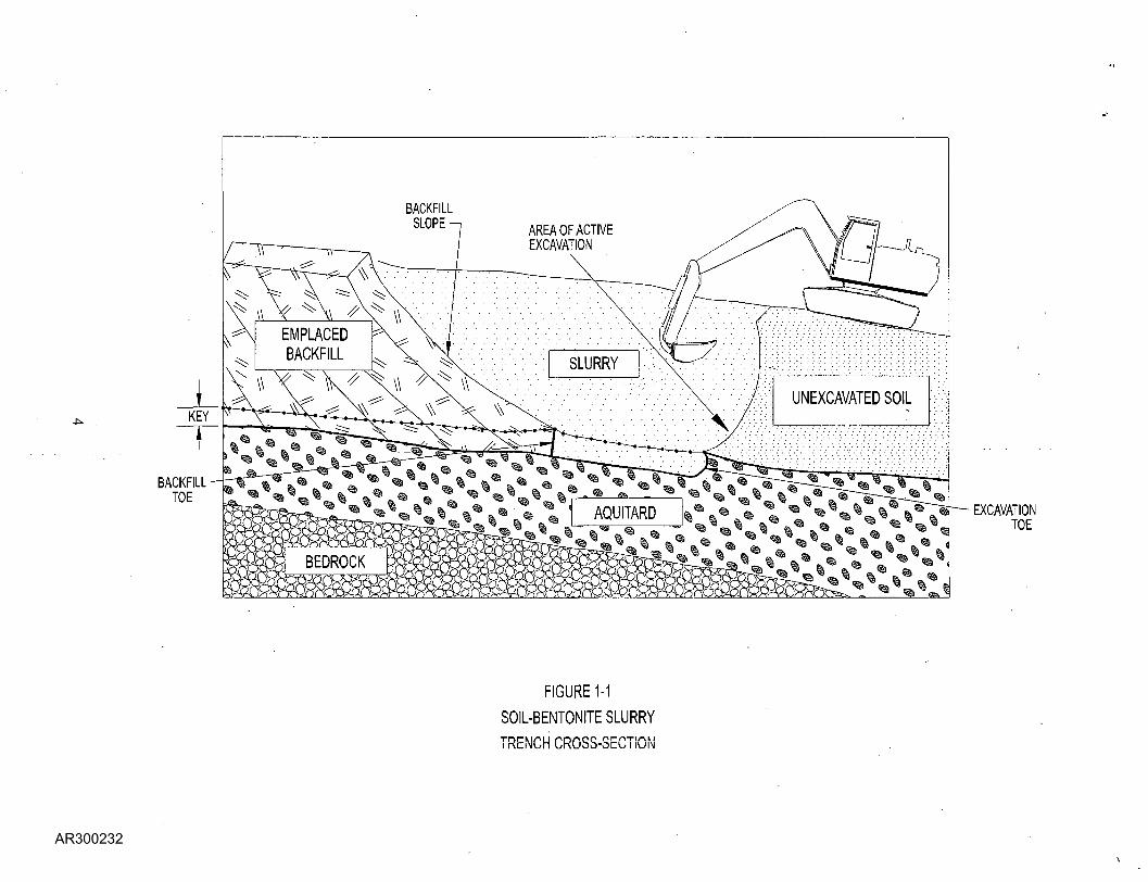
AREA OF ACTIVEEXCAVATION
BACKFILLTOE
EXCAVATIONTOE
FIGURE 1-1
SOIL-BENTONITE SLURRY
TRENCH CROSS-SECTION
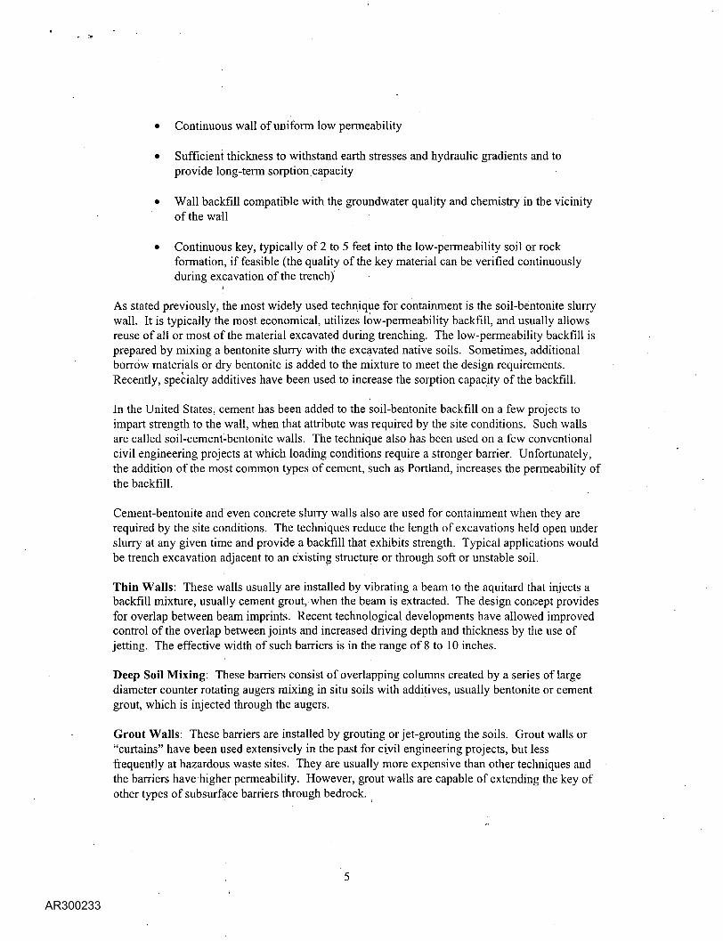
• Continuous wall of uniform low permeability
• Sufficient thickness to withstand earth stresses and hydraulic gradients and toprovide long-term sorption.capacity
• Wall backfill compatible with the groundwater quality and chemistry in the vicinityof the wall
• Continuous key, typically of 2 to 5 feet into the low-permeability soil or rockformation, if feasible (the quality of the key material can be verified continuouslyduring excavation of the trench)
,i • ;
As stated previously, the most widely used technique for containment is the soil-beritonite slurrywall. It is typically the most economical, utilizes low-permeability backfill, and usually allowsreuse of all or most of the material excavated during trenching. The low-permeability backfill isprepared by mixing a bentonite slurry with the excavated native soils. Sometimes, additionalborrow materials or dry bentonite is added to the mixture to meet the design requirements.Recently, specialty additives have been used to increase the sorption capacity of the backfill.
In the United States, cement has been added to the soil-bentonite backfill on a few projects toimpart strength to the wall, when that attribute was required by the site conditions. Such wallsare called soil-cement-bentonite walls. The technique also has been used on a few conventionalcivil engineering projects at which loading conditions require a stronger barrier. Unfortunately,the addition of the most common types of cement, such as Portland, increases the permeability ofthe backfill.
Cement-bentonite and even concrete slurry walls also are used for containment when they arerequired by the site conditions. The techniques reduce the length of excavations held open underslurry at any given time and provide a backfill that exhibits strength. Typical applications wouldbe trench excavation adjacent to an existing structure or through soft or unstable soil.
Thin Walls: These walls usually are installed by vibrating a beam to the aquitard that injects abackfill mixture, usually cement grout, when the beam is extracted. The design concept providesfor overlap between beam imprints. Recent technological developments have allowed improvedcontrol of the overlap between joints and increased driving depth and thickness by the use ofjetting. The effective width of such barriers is in the range of 8 to 10 inches.
Deep Soil Mixing: These barriers consist of overlapping columns created by a series of largediameter counter rotating augers mixing in situ soils with additives, usually bentonite or cementgrout, which is injected through the augers.
Grout Walls: These barriers are installed by grouting or jet-grouting the soils. Grout walls or"curtains" have been used extensively in the past for civil engineering projects, but lessfrequently at hazardous waste sites. They are usually more expensive than other techniques andthe barriers have higher permeability. However, grout walls are capable of extending the key ofother types of subsurface barriers through bedrock.

Sheet Pile Walls: These barriers traditionally have consisted of steel sheeting with some type ofinterlock joint. Recently, such sheeting includes an improved interlock design to accommodatesealing of joints; several innovative techniques have been developed recently to seal and test thejoints between sheet piles. In addition, plastic has been substituted for steel in a number ofapplications (see Figure 1-2).
Liners: Liners also have been used as vertical barriers, either alone or in conjunction with slurrywalls.
A main concern in the application of these technologies is control of the key into the aquitard. Itshould be noted that the slurry trench excavation method is the only one that permits visualinspection of the key material and assurance of the key-in depth during construction. AppendixA describes construction methods used to install vertical barriers.
The applicability of a particular method at a site depends on the in situ groundwater conditions,soil and rock conditions, permeability desired, depth of installation, presence of adjacentstructures, and cost considerations. For example, at one site studied, two walls were installed.The outer wall was constructed by the slurry trench excavation and backfill method as theprimary barrier to migration of contaminated groundwater. An inner wall also was constructedby the vibrating beam.method to limit the area of active (that is, pumping) containment.
Caps ,
To meet the performance standards set forth under RCRA Subtitle C, the cap design shouldinclude the following layers (EPA 1989):
• A base soil layer to support the other layers• A low-permeability layer (1 x 10'cm/sec or less)• A drainage layer• A soil cover, including a vegetative layer
A gas collection and venting layer maybe required to control contained gases, such as methane.The gas collection layer typically is constructed of granular soils and collection and vent pipes.The low-permeability layer is constructed of clays and geosynthetic material (geosynthetic clayliners as a substitute for clay and geomembranes). The drainage layer is constructed of granularsoils, or geosynthetic materials, and the soil cover usually is silty soils. The vegetative layerconsists of topsoil that supports vegetation. In industrial areas, a parking lot or other alternativesurface can be constructed over the soil cover. Appendix A. provides details of typical capdesign, construction, GQA/CQC, and cost.
1.1.3 Previous Studies
Previous studies have focused on the performance of caps, especially the stability of caps in casesin which geosynthetic materials are used (EPA 1993). The performance of different Jow-permeability soil mixtures for use in vertical barriers has been studied to a lesser degree, butsome notable works are available (U.S. Army Corps of Engineers [USAGE] 1996; Evans 1994).
DEVELOPMENT AND
SCREENING OF ALTERNATIVES
FROM:• PreDminaiy
Assessment• 8»« Inspection
NPL Using /
i TOEATABIUTYCHARACTERIZATION , INVESTIGATION
SCOPING OF THE RUFS
AILED ANALYSISTERNATTVES
DEVELOPMENT ANDSCREENING
OF ALTERNATIVES
TO:• Remedy Selection• Record of Decision• Remedial Design• Remedial Action
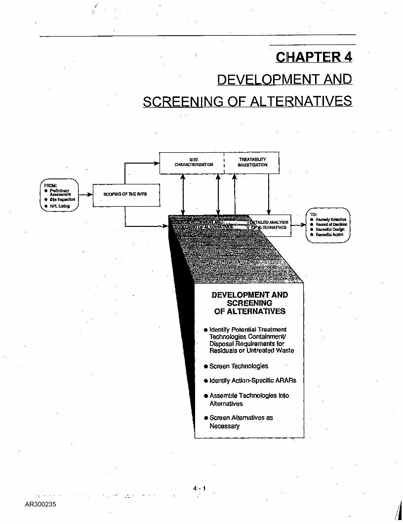
• Identify Potential TreatmentTechnologies Containment/Disposal Requirements forResiduals or Untreated Waste
• Screen Technologies
• Identify Action-Specific ARARs
• Assemble Technologies intoAlternatives
• Screen Alternatives asNecessary
\Wqrjd-searchable version_- Not a true copy \
4 - 1
Chapter 4Development and Screening of Alternatives
4.1 Introduction
4.1.1 Purpose of Alternative Development andScreening
The primary objective of this phase of the FS is to developan appropriate range of waste management options thatwill be analyzed more fully in the detailed analysis phaseof the FS. Appropriate waste management options thatensure the protection of human health and theenvironment may involve, depending on site-specificcircumstances, the complete elimination or destruction ofhazardous substances at the site, the reduction of'concentrations of hazardous substances to acceptablehealth-based levels, and prevention of exposure tohazardous substances via engineering or institutionalcontrols, or some combination of the above. Alternativesare typically developed concurrently with the Rl sitecharacterization, with the results of one influencing theother in an iterative fashion (i.e., Rl site characterizationdata are used to develop alternatives and screentechnologies, whereas the range of alternatives developedguides subsequent site characterization and/ortreatabilitystudies). An overview of the entire FS process ispresented in the following subsections.
4.1.2 FS Process Overview
The FS may be viewed (for explanatory purposes) asoccurring in three phases: the development of alternatives,the screening of the alternatives, and the detailedanalysis of alternatives. However, in actual practice thespecific point at which the first phase ends and thesecond begins is not so distinct. Therefore, thedevelopment and screening of alternatives are discussedtogether to better reflect the interrelatedness of theseefforts. Furthermore, in those instances in whichcircumstances limit the number of available options, andtherefore the number of alternatives that are developed, itmay not be necessary to screen alternatives prior to thedetailed analysis.
4.1.2.1 Development and Screening ofAlternatives
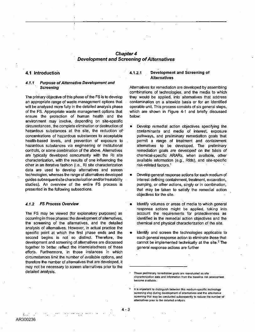
Alternatives for remediation are developed by assemblingcombinations of technologies, and the media to whichthey would be applied, into alternatives that addresscontamination on a sitewide basis or for an identifiedoperable unit. This process consists of six general steps,which are shown in Figure 4-1 and briefly discussedbelow:
• Develop remedial action objectives specifying thecontaminants and media of interest, exposurepathways, and preliminary remediation goals thatpermit a range of treatment and containmentalternatives to be developed. The preliminaryremediation goals are developed on the basis ofchemical-specific ARARs, when available, otheravailable information (e.g., Rfds), and site-specificrisk-related factors.1
• Develop general response actions for each medium ofinterest defining containment, treatment, excavation,pumping, or other actions, singly or in combination,that may be taken to satisfy the remedial actionobjectives for the site.
• Identify volumes or areas of media to which generalresponse actions might be applied, taking intoaccount the requirements for protectiveness asidentified in the remedial action objectives and thechemical and physical characterization of the site.
• Identify and screen the technologies applicable toeach general response action to eliminate those thatcannot be implemented technically at the site.2 Thegeneral response actions are further
These preliminary remediation goals are reevaluated as sitecharacterization data and information from the baseline risk assessmentbecome available.
4 - 3
It is important to distinguish between this medium-specific technologyscreening step during development of alternatives and the alternativescreening that may be conducted subsequently to reduce the number ofalternatives prior to the detailed analysis.
\W0rd-searcfaablej>ersiqn -^fpta_ true copy _
V_Scoping
S_Establish Remedial Action Objectives
iDevelop General ResponseActions Describing Areas orVolumes of Media to WhichContainment Treatment, or
Removal Actions May Be Applied
IIdentify PotentialTreatment and
Disposal Technologiesand Screen Based on
Technical Implementability
Evaluate Process Options Basedon Effectiveness, Implementability,
and Relative Cost to Select aRepresentative Process for each
Technology Type
Repeat Previous Scoping Steps:- Determine New Data Needs- Develop Sampling Strategies
and Analytical Support toAcquire Additional Data
-RepeatSteps in RlSiteCharacterization
Combine Media-SpecificTechnologies into
Alternatives
Detailed Analysisof Alternatives
Figure 4-1 Alternative development.
4 -4
Word-searchablejversion -Nota true copy
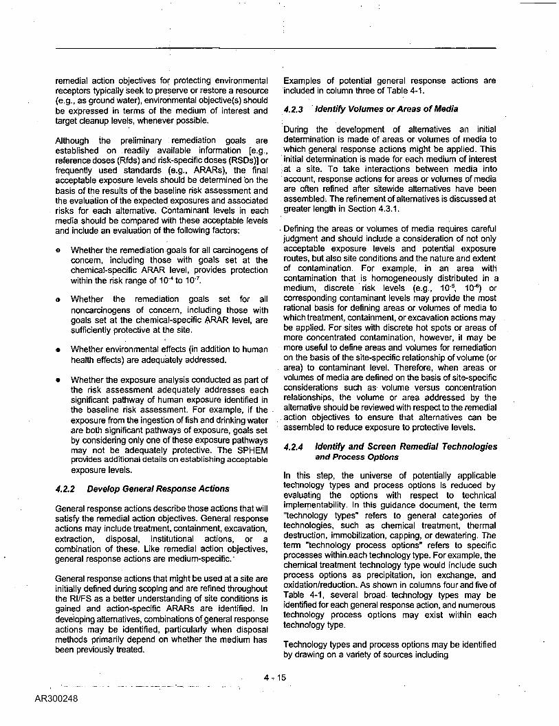
defined to specify remedial technology types (e.g.,the general response action of treatment can befurther defined to include chemical or biologicaltechnology types).
« Identify and evaluate technology process options toselect a representative process for each technologytype retained for consideration. Although specificprocesses are selected for alternative developmentand evaluation, these processes are intended torepresent the broader range of process options withina general technology type.
« Assemble the selected representative technologiesinto alternatives representing a range of treatment andcontainment combinations, as appropriate.
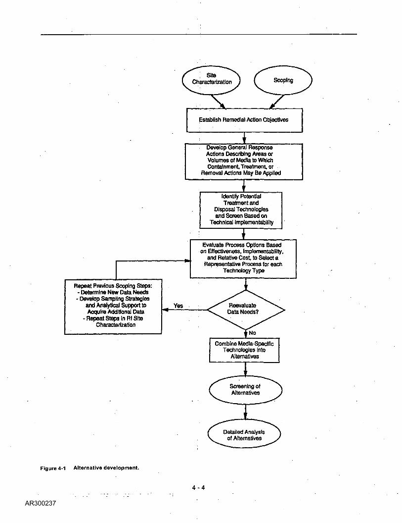
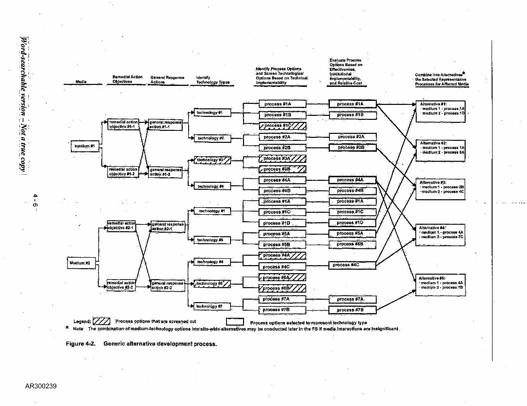
Figure 4-2 provides a generic representation of thisprocess. Section 4.2 contains a more detailed descriptionand specific examples of alternative development.
For those situations in which numerous wastemanagement options are appropriate and developed, theassembled alternatives may need to be refined andscreened to reduce the number of alternatives that will beanalyzed in detail. This screening aids in streamlining thefeasibility study process while ensuring that the mostpromising alternatives are being considered.
As discussed earlier, in other situations the number ofviable or appropriate alternatives for addressing siteproblems may be limited; thus, the screening effort maybe minimized or eliminated if unnecessary. The scope ofthis screening effort can vary substantially depending onthe number and type of alternatives developed and theextent of information necessary for conducting thedetailed analysis. The scope and emphasis can also varydepending on either the degree to which the assembledalternatives address the combined threats posed by theentire site or on the individual threats posed by separatesite areas or contaminated media. Whatever the scope,the range of treatment and containment alternativesinitially developed should be preserved through thealternative screening process to the extent that it makessense to do so.
As part of the screening process, alternatives areanalyzed to investigate interactions among media interms of both the evaluation of technologies (i.e., theextent to which source control influences the degree ofground-water or air-quality control) and sitewideprotectiveness (i.e., whether the alternative providessufficient reduction of risk from each media and/orpathway of concern for the site or that part of the sitebeing addressed by an operable unit). Also at this stage,the areas and quantities of contaminated
media initially specified in the general response actionsmay also be reevaluated with respect to the effects ofinteractions between media. Often, source control actionsinfluence the degree to which ground-water remediationcan be accomplished or the time frame in which it can beachieved. In such instances, further analyses may beconducted to modify either the source control orground-water response actions to achieve greatereffectiveness in sitewide alternatives. Using these refinedalternative configurations, more detailed information aboutthe technology process options may be developed. Thisinformation might include data on the size and capacitiesof treatment systems, the quantity of materials requiredfor construction, and the configuration and designrequirements for groundwater collection systems.
Information available at the time of screening should beused primarily to identify and distinguish any differencesamong the various alternatives and to evaluate eachalternative with respect to its effectiveness,implementability, and cost. Only the alternatives judgedas the best or most promising on the basis of theseevaluation factors should be retained for furtherconsideration and analysis.3 Typically, those alternativesthat are screened out will receive no further considerationunless additional information becomes available thatindicates further evaluation is warranted. As discussed inSection 4.2.6, for sites at which interactions amongmedia are not significant, the process of screeningalternatives, described here, may be applied tomedium-specific options to reduce the number of optionsthat will either be combined into sitewide alternatives atthe conclusion of screening or will await further evaluationin the detailed analyses. Section 4.3 contains more detailabout screening alternatives.
4.1.2.2 Detailed Analysis of Alternatives
During the detailed analysis, the alternatives broughtthrough screening are further refined, as appropriate, andanalyzed in detail with respect to the evaluation criteriadescribed in Chapter 6. Alternatives may be further refinedand/or modified based on additional site characterizationor treatability studies conducted as part of the Rl. Thedetailed analysis should be conducted so thatdecision-makers are provided with sufficient information tocompare alternatives with respect to the evaluation criteriaand to select an appropriate remedy. Analysis activitiesare described in greater detail in Chapter 6.
3 As with the use of representative technologies, alternativesmay be selected to represent sufficiently similar managementstrategies; thus, in effect, a separate analysis for eachalternative is not always warranted.
Word-searchableyersion ^JNota true copy \
4 - 5
If!
I
a •
ili-I-
a>
MediaRemedial Action General Response IdentifyObjectives Actions Technology Types
remedial actior^-*>objective;|i2-2
H» remedial action I—>J general responseobjecflye: -1 \. faction #1-1
remedial action f ] general responseobjective #1-2 | »j acUpn #1 -2
general .responseaction #2-2'
-»| technology #1 [r
technology #5
technology «4
Identify Process Optionsand Screen Technologies;Options Based on TechnicalImplementabllity
Evaluate ProcessOptions Based onEffectiveness,InstitutionalImplementabllity,and Relative Cost .
process #1D . .[ ' [[3 prQcess *t1p
i
'•j process frtC . . . ]*
. H technojogy ~f>/\ :
*) technology fi1 process #7B
Legend:
* Note
Figure 4-2.
"\, process;*^ ^| [ process #5A
[ i [ process #58
-| process #4C
process #7 A
1 process #7B
.Process options that are screened out
Generic alternative development process.
Process options selected to represent technology type
Combine into Alternatives*the Selected RepresentativeProcesses for Affected Media
Alternative #1:• medium i - process 1 A• medium'2 - process.lD
Alternative #2:• medium i t process 1A• medium 2 - process 6A
Alternative S3:• medium 1 - process 2B•'medium^ • process 4C
Alternative <M:• medium 1 - process 4A} medium 2 - process<7C
Alternative #5:• medium 1 - process 4A• medium 2 - process 7B

4.1.3 Alternative Ranges
Alternatives should be developed that will providedecision-makers with an appropriate range of options andsufficient information to adequately compare alternativesagainst one another. In developing alternatives, the rangeof options will vary depending on site-specific conditions.A general description of ranges for.source control andgroundwater response actions that should be developed,as appropriate, are described below.
4.1.3.1 Source Control Actions
For source control actions, the following types ofalternatives should be developed to the extent practicable:
« A number of treatment alternatives ranging from onethat would eliminate or minimize to the extentfeasible the need for long-term management(including monitoring) at a site to one that would usetreatment as a primary component of an alternative toaddress the principal threats at the site.4 Alternativeswithin this range typically will differ in the type andextent of treatment used and the managementrequirements of treatment residuals or untreatedwastes.
« One or more alternatives that involve containment ofwaste with little or no treatment but protect humanhealth and the environment by preventing potentialexposure and/or reducing the mobility ofcontaminants.
• A no-action alternative5
Figure 4-3 conceptually illustrates this range for sourcecontrol alternatives.
Development of a complete range of treatment alternativeswill not be practical in some situations. For example, forsites with large volumes of low concentrated wastes suchas some municipal landfills and mining sites, analternative that eliminates the need for long-termmanagement may not be reasonable given siteconditions, the limitations of technologies, and extremecosts that may be involved. If a full range of alternatives is
4 Alternatives for which treatment is a principal element couldinclude containment elements for untreated waste or treatmentresiduals as well.
5 Although a no-action alternative may include some type ofenvironmental monitoring, actions taken to reduce the potentialfor exposure (e.g., site fencing, deed restrictions) should not beincluded as a component of the no-action alternatives. Suchminimal actions should constitute a separate "limited" actionalternative.
not developed, the specific reasons for doing so should bebriefly discussed in the FS report to serve asdocumentation that treatment alternatives were assessedas required by CERCLA.
4.1.3.2 Ground-water Response Actions
For ground-water response actions, alternatives shouldaddress not only cleanup levels but also the time framewithin which the alternatives might be achieved.Depending on specific site conditions and the aquifercharacteristics, alternatives should be developed thatachieve ARARs or other health-based levels determinedto be protective within varying time frames using differentmethodologies. For aquifers currently being used as adrinking water source, alternatives should be configuredthat would achieve ARARs or risk-based levels as rapidlyas possible. More detailed information on developingremedial alternatives for ground-water response actionsmay be found in "Guidance on Remedial Actions forContaminated Ground Water at Superfund Sites" (U.S.EPA, August 1988).
4.2 Alternative Development Process
The alternative development process may be viewed asconsisting of a series of analytical steps that involvesmaking successively more specific definitions of potentialremedial activities. These steps are described in thefollowing sections.
4.2.1 Develop Remedial Action Objectives
Remedial action objectives consist of medium-specific oroperable unit-specific goals for protecting human healthand the environment. The objectives should be as specificas possible but not so specific that the range ofalternatives that can be developed is unduly limited.Column two of Table 4-1 provides examples of remedialaction objectives for various media.
Remedial action objectives aimed at protecting humanhealth and the environment should specify:
• The contaminant(s) of concern
• Exposure route(s) and receptor(s)
• An acceptable contaminant level or range of levels foreach exposure route (i.e., a preliminary remediationgoal)
Remedial action objectives for protecting human receptorsshould express both a contaminant level and an exposureroute, rather than contaminant levels alone, becauseprotectiveness may be achieved by reducing exposure(such as capping an area, limiting access, or providing analternate water supply) as well as by reducingcontaminant levels. Because
4 - 7
Word-searchable^yersion —lNot_ajtru_e copy \

1. No action:Hot" Spots
SoilExceeds
SoilExceeds1x1cr6Risk
Background
2. Treatment which eliminates or minimizes to the extent feasible the need for long-termmanagement.
2A. All Contaminated SoilExcavated and Treated
2B. All Soil Above 1x10Excavated & Treated
\Wqrd-searchable_versiqn -Not a true copyj
4 - 8

3. Alternatives using treatment as a principal element
"Hot" Spots Excavated& Treated
4. Containment with little or no treatment
Cap_•_•_•_•_•_•_•_
• i i toS;li»l».: &t*>&:t.MiM®^^«l;iS^&8&8i&*
4 - 9
Word-searchable version - Not a true cgpyj

Table 4-1. Example of Remedial Action Objectives, General Response Actions, Technology Types, and ExampleProcess Options for the Development and Screening of Technologies
EnvironmentalMedia
Remedial Action Objectives(from site characterization)
General Response Actions(for all remedial action objectives)
Remedial Technology Types(for general response actions) Process Options
Ground Water For Human Health;
Prevent ingestion of water having[carcinogen(s)] in excess of[MCL(s)] and a total excess cancerrisk (for all contaminants)ofgreater than 10-' to 10''.
No Action/Institutional Actions:No actionAlternative residential water supplyMonitoring
Containment Actions:Containment
No Action/ Institutional options:FencingDeed restrictions
Containment Technologies:CappingVertical barriersHorizontal barriers
Clay cap, synthetic membrane, multi-layerSlurry wall, sheet pilingLiners, grout injection
Prevent ingestion of water having[non-carcinogentsl] in excess of[MCLJs] or [reference dose(s)].
Collection/Treatment Actions:Collection/treatment discharge/ in -situ groundwater treatment
Individual home treatment units
Extraction technologies:Ground water collection/pumpingEnhanced removal
Wells, subsurface or leachate collectionSolution mining, vapor extraction, enhancedoil recovery
For Environmental Protection
Restore ground water aquifer to[concentration(s)] for[contaminant(s)] .
Treatment technologies:Physical treatment
Chemical treatment
In situ treatment
Coagulation/flocculation, oil-water-seperation, air stripping, adsorptionNeutralization, precipitation, ion exchangeoxidation/reductionSubsurface bioreclamation
Disposal'Technologies:Discharge to POTW (aftertreatment)
Discharge to surface water(after treatment)
Soil For Human Health
Prevent ingestion/direct contactwith soil having [non-car cinogen(s)] in excess of[reference dose(s)].
Prevent direct contact/ ingestionwith soil having 10'4 to 10'* excesscancer risk from [carcinogen(s)) .
Prevent inhalation of[carcinogen(s)] posing excess risklevels of 10"' to 10'*.
For Environmental Protection;Prevent migration of contaminantsthat would result in ground watercontamination in excess oc[concentration!3)! for[contaminant(s)].
No Action/Institutional Actions:No actionAcess restriction
Containment Actions:Containment
Excavation/Treatment Actions:Excavation/ treatment/disposal
In situ treatmentDisposal excavation
No Action/Institutional Actions:FencingDeed restrictions
Containment Technologies:CappingVertical barriersHorizontal barriersSurface controls
Sediment control barriersDust control
Removal technologies:Excavation
Treatment Technologies:Solidfacation, fixation,stabilization, imnobilization,DewateringPhysical treatmentChemical treatmentBiological treatmentIn situ treatmentThermal treatment
Clay cap, synthetic membrane, multi-layerSlurry wall, sheet piling Liners, groutinjectionDiversion/collection, grading, soilstabilization
Coffer dams, curtain barriers, Revegetatioh,capping *
Solids excavation
Sorption, pozzolanic agents, encapsulationBelt filter press, dewatering, and dryingbedsWater/solvent leaching (with subsequentliquids treatment)Lime neutralizationCultured micro-organismSurface bio-remediationIncineration, pyrolysis
4-10

Table 4-1. Continued
EnvironmentalMedia
Surface Water
Remedial Action Objectives(from site characterization)
General Response Actions(for all remedial action objectives)
For Human Health:
prevent ingestion of water having[carcinogen(s)]in excess of[MCL(s)] and a total excess cancerrisk (for all contaminants)ofgreater than 10'4 to 10"'.
Prevent ingestion of water having[non-carcinogen(s) ] in excess of[MCL)s] or [reference dose (s)] .•
For Environmental Protection
Restore surface water to [ambientater quality criteria] for[contaminant(s)].
No Action/Institutional Actions:No actionAcess restrictionsMonitoring
Collection/Treatment Actions:Surface water runoff interception/treatment/discharge
Remedial Technology Types(for general response actions)
No Action/ Institutional Options:FencingDeed restrictions
Collection Technologies:Surface controls
Treatment Technologies:Physical treatment
Chemical treatment
Biological treatment(organics)In situ treatment
Disposal Technologies:Discharge to POTW (aftertreatment)
Process Options
Grading, diversion, and collection
Coagulation/flocculation, oil-waters'eperation, filtration, adsorption
Precipitation, ion exchange, neutralization,freeze crystalization biological treatment.Aerobic and anaerobic spray irragation
In situ precipitation, in situ bioreclamation
Sediment For Human Health:
Prevent direct contact withsediment having [carcinogen(s)] inexcess of 10"* to 10° excess cancerrisk.
. For Environmental Protection
Prevent releases of[contaminant(s)] from sedimentsthat would result in surface waterlevels in excess of [ambient waterquality criteria] .
No Action/Institutional Actions:No actionAcess restrictions toMonitoring
Excavation Actions:Excavation
Excavation/Treatment Actions:Removal/disposalRemoval/treatment/disposal
No Action/Institutional Actions:FencingDeed restrictions
Removal Technologies:Excavation
Containment Technologies:CappingVertical barriersHorizontal'barriersSediment control barriers
Treatment Technologies:Solidfacation, fixation,stabilization,DewateringPhysical treatment
Chemical treatment
Biological treatmentIn situ treatmentThermal treatment
Sediments excavation
Removal with clay cap, multi-layer, asphaltSlurry wall, sheet pilingLiners, grout injectionCoffer dams, curtain barriers, Revegetation,capping barriers
Sorption, pozzolanic agents, encapsulation
Sedimentation, dewatering, and drying bedsWater/solids leaching (with subsequenttreatment)Neutralization, oxidation, electrochemicalreductionLandfarmingSurface bioreclemationIncineration, pyrolysis
Air For Human Health;
Prevent inhalation of[carcinogen(s)] in excess of 10"'to 10"' excess cancer risk.
No Action/Institutional Actions:No action
. Acess restrictions to Monitoring
Collection Actions:Gas collection
No Action/ Institutional Options:FencingDeed restrictions
Removal Technologies:Landfill gas collection Passive vents, active gas collection systems
^Vord-searchable version^-Not a true copy]
4-11

Table 4-1. Continued
EnvironmentalMedia
Structures
Remedial Action Objectives(from site characterization)
General Response Actions(for all remedial action objectives)
For Human Health;
Prevent direct contact withsediment having [carcinogen(s)] inexcess of 10'' to 10-7 excess cancerrisk.
Prevent migration of[carcinogen(s)] which would resultin ground water concentrations inexcess of 10'4 to 10"' total excesscancer risk level.
Prevent-migration .of[carcinogen(s)] which would resultin soil concentrations in excessof [reference dose(s)].
For environmental Protection
Prevent migration of[contaminants] that would resultin ground water concentrations inexcess of [concentration(s)].
No Action/Institutional Actions:No actionAcess restrictionsDemolition/Treatment Actions:Demolition/disposalDecontamination
Remedial Technology Types(for general response actions)
No Action/Institutional Options:FencingDeed restrictions
Removal Technologies:DemolitionExcavation
Treatment Technologies:Solids processing
Solids treatment
Process Options
Demolition- -Excavation, debris removal
Magnetic processes, crushing and grinding,screeningWater leaching, solvent leaching, steamcleaning
Solid Wastes For Human Health;
Prevent ingestion/direct contactwith wastes having [non-carcinogen(s)] in excess of[reference dose(s)].
Prevent ingestion/direct contactwith wastes having 10'4 to 10''excess cancer risk from[carcinogen (s)].
I Prevent inhalation of[carcinogen(s)] posing excesscancer risk levels of 10"4 to 10'7.
Prevent migration of[carcinogen(s) ] that would resultin ground water concentrations inexcess of [MCLs] or 10'4 to 10'7
total excess cancer risk levels.
No Action/Institutional Actions:No actionAcess"restriction to [location]
Containment Actions:Containment
Excavation/Treatment Actions;Removal/disposal
Removal/treatment/disposal
No Action/Institutional Options:. FencingDeed restrictions
Containment Technologies:CappingVertical barriersHorizontal barriers
Removal Technologies:ExcavationDrum removal
Treatment Technologies:Physical treatment
Chemical treatmentBiological treatmentThermal treatment
Solids processing
Clay cap, synthetic membrane, multi-layerSlurry wall, sheet pilingLiners, grout injectionDust controls •
Solids excavationDrum and debris removal
water/solvent leaching (with subsequentliquids treatment) 'NeutralizationCultured micro-organismsIncineration, pyrolysis, gaseous incinerationCrushing and grinding, screening,classifacation
I Word-searchable version - Not a true
4-12
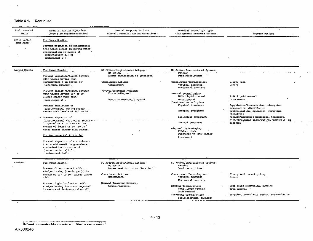
Table 4-1. Continued
EnvironmentalMedia
Solid Wastes(continued)
Remedial Action Objectives(from site characterization)
For Human Health;
Prevent migration of contaminantsthat would result in ground watercontamination in excess of[concentration(s)] of[contaminant (s)] .
General Response Actions(for-all remedial action objectives)
Remedial Technology Types(for general response actions) Process Options
Liquid .wastes . For Human Health;
Prevent ingestion/direct contactwith wastes having [non-carcinogen (s) 3 in excess of-[reference dose(s)].
prevent ingestion/direct contactwith wastes having 10"* to 10"T
excess cancer risk from[carcinogen(s)J.
. Prevent inhalation of[carcinogen(s)] posing excesscancer risk levels of 10"' to 10''.
- Prevent migration of• - - - • - - [carcinogen(s)l that would result
in ground water concentrations inexcess of [MCLs] or 10"* to 10"T
total excess cancer risk levels.
For Environmental Protection;
Prevent migration of contaminantsthat would result in groundwatercontamination in excess of[concentration(s)) for[contaminant (s)].
No Action/Institutional Actions:No actionAxcess restriction to [location]
Containment Actions:Containment
Removal/Treatment Actions:Removal/disposal
Removal/treatment/disposal
No Action/Institutional Options:Fencing" ' " " "Deed .restrictions
Containment Technologies:Vertical barriersHorizontal barriers
Removal Technologies:Bulk liquid removalDrum removal
Treatment Technologies:Physical treatment
Chemical treatment
Biological treatment
Thermal treatment
Disposal Technologies:Product reuseDischarge to POTW (aftertreatment)
Slurry wallLiners
Bulk liquid removalDrum removal
Coagulation/flocculation, adsorption,evaporation, distillationNeutralization, oxidation, reduction,photolysisAerobic/anaerobic biological treatment,biotechnologies Incineration, pyrolysis, co-disposal
Sludges For Human Health;
Prevent direct contact withsludges having [carcinogen(s)]inexcess of 10'* to 10'7 excess cancerrisk.
Prevent ingestion/contact withsludges having [non-carcinogen(s)]in excess of [reference dose(s)]'.
NO Action/Institutional Actions:No actionAxcess restriction to [location]
Containment Actions:Containment
Removal/Treatment Actions:Removal/disposal
NO Action/Institutional Options:FencingDeed restrictions
Containment Technologies:Vertical barriersHorizontal barriers
Removal Technologies:Bulk liquid removalDrum removal
Treatment Technologies:Solidification, fixation
Slurry wall, sheet pilingLiners
Semi-solid excavation, pumpingDrum removal
Sorption, pozzolanic agents, encapsulation
version-Nota true copy \
4-13

Table 4-1. Continued
EnvironmentalMedia
Sludges(continued)
Remedial Action Objectives(from site characterization)
General Response Actions(for all remedial action objectives)
Prevent migration of[carcinogen(s)] that would resultin ground water concentrations inexcess of 10'4 to 10'7 excess cancerrisk levels.
For Environmental Protection:
Prevent releases of[contaminant(s)] from sludge thatwould result in surface waterlevels in excess of [ambient waterquality criteria].
Prevent releases of[contaminant(s)] from sludge thatwould result in ground waterlevels of [contaminant (s)] inexcess of (concentration(s)l .
Removal/Treatment/disposal
Remedial Technology Types(for general response actions)
Physical treatment
Chemical treatmentBiological treatment
Thermal treatment (organics)Dewatering
Disposal Technologies:Product reuseLandfilling (after treatment)
Process Options
Freeze crystallization, neutralization,oxidation, electrochemical reductionOxidation, reduction, photolysisAerobic/anaerobic treatment, land-treatmentnew biotechnologiesIncineration, pyrolysis, co-disposalGravity thickening, belt filter press, vacuumfiltration
4-14
remedial action objectives for protecting environmentalreceptors typically seek to preserve or restore a resource(e.g., as ground water), environmental objective(s) shouldbe expressed in terms of the medium of interest andtarget cleanup levels, whenever possible.
Although the preliminary remediation goals areestablished on .readily available information [e.g.,reference doses (Rfds) and risk-specific doses (RSDs)] orfrequently used standards (e.g., ARARs), the finalacceptable exposure levels should be determined on thebasis of the results of the baseline risk assessment andthe evaluation of the expected exposures and associatedrisks for each alternative. Contaminant levels in eachmedia should be compared with these acceptable levelsand include an evaluation of the following factors:
o Whether the remediation goals for all carcinogens ofconcern, including those with goals set at thechemical-specific ARAR level, provides protectionwithin the risk range of 10'4 to 10'7.
» Whether the remediation goals set for allnpncarcinogens of concern, including those withgoals set at the chemical-specific ARAR level, aresufficiently protective at the site.
• Whether environmental effects (in addition to humanhealth effects) are adequately addressed.
• Whether the exposure analysis conducted as part ofthe risk assessment adequately addresses eachsignificant pathway of human exposure identified inthe baseline risk assessment. For example, if theexposure from the ingestion offish and drinking waterare both significant pathways of exposure, goals setby considering only one of these exposure pathwaysmay not be adequately protective. The SPHEMprovides additional details on establishing acceptableexposure levels.
4.2.2 Develop General Response Actions
General response actions describe those actions that willsatisfy the remedial action objectives. General responseactions may include treatment, containment, excavation,extraction, disposal, institutional actions, or acombination of these. Like remedial action objectives,general response actions are medium-specific/
General response actions that might be used at a site areinitially defined during scoping and are refined throughoutthe RI/FS as a better understanding of site conditions isgained and action-specific ARARs are identified. Indeveloping alternatives, combinations of general responseactions may be identified, particularly when disposalmethods primarily depend on whether the medium hasbeen previously treated.
Examples of potential general response actions areincluded in column three of Table 4-1.
4.2.3 Identify Volumes or Areas of Media
During the development of alternatives an initialdetermination is made of areas or volumes of media towhich general response actions might be applied. Thisinitial determination is made for each medium of interestat a site. To take interactions between media intoaccount, response actions for areas or volumes of mediaare often refined after sitewide alternatives have beenassembled: The refinement of alternatives is discussed atgreater length in Section 4.3.1.
Defining the areas or volumes of media requires carefuljudgment and should include a consideration of not onlyacceptable exposure levels and potential exposureroutes, but also site conditions and the nature and extentof contamination. For example, in an area withcontamination that is homogeneously distributed in amedium, discrete risk levels (e.g., 10~5, 10~6) orcorresponding contaminant levels may provide the mostrational basis for defining areas or volumes of media towhich treatment, containment, or excavation actions maybe applied. For sites with discrete hot spots or areas ofmore concentrated contamination, however, it may bemore useful to define areas and volumes for remediationon the basis of the site-specific relationship of volume (orarea) to contaminant level. Therefore, when areas orvolumes of media are defined on the basis of site-specificconsiderations such as volume versus concentrationrelationships, the volume or area addressed by thealternative should be reviewed with respect to the remedialaction objectives to ensure that alternatives can beassembled to reduce exposure to protective levels.
4.2.4 Identify and Screen Remedial Technologiesand Process Options
In this step, the universe of potentially applicabletechnology types and process options is reduced byevaluating the options with respect to technicalimplernentability. In this guidance document, the term"technology types" refers to general categories oftechnologies, such as chemical treatment, thermaldestruction, immobilization, capping, or dewatering. Theterm "technology process options" refers to specificprocesses within.each technology type. For example, thechemical treatment technology type would include suchprocess options as precipitation, ion exchange, andoxidation/reduction.. As shown in columns four and five ofTable 4-1, several broad technology types may beidentified for each general response action, and numeroustechnology process options may exist within eachtechnology type.
Technology types and process options may be identifiedby drawing on a variety of sources including
4-15
Word-searchable^ version-Not a true copy j

references developed for application to Superfund sitesand more standard engineering texts .not specificallydirected toward hazardous waste sites. Some of thesesources are included in Appendix D of this document.
During this screening step, process options and entiretechnology types are eliminated from further considerationon the basis of technical implementability. This isaccomplished by using readily available information fromthe Rl site characterization on contaminant types andconcentrations and onsite characteristics to screen outtechnologies and process options that cannot beeffectively implemented at the site.
Two factors that commonly influence technologyscreening are the presence of inorganic contaminants,which limit the applicability of many types of treatmentprocesses, and the subsurface conditions, such as depthto impervious formations or the degree of fracture inbedrock, which can limit many types of containment andground-water collection technologies. This screening stepis site-specific, however, and other factors may need tobe considered. Figure 4-4 provides an example of initialtechnology screening for ground-water remediation at asite having organic and inorganic contaminants andshallow, fractured bedrock.
As with all decisions during an RI/FS, the screening oftechnologies should be documented. For most studies, afigure similar to Figure 4-4 provides adequate informationfor this purpose and can be included in the FS report.
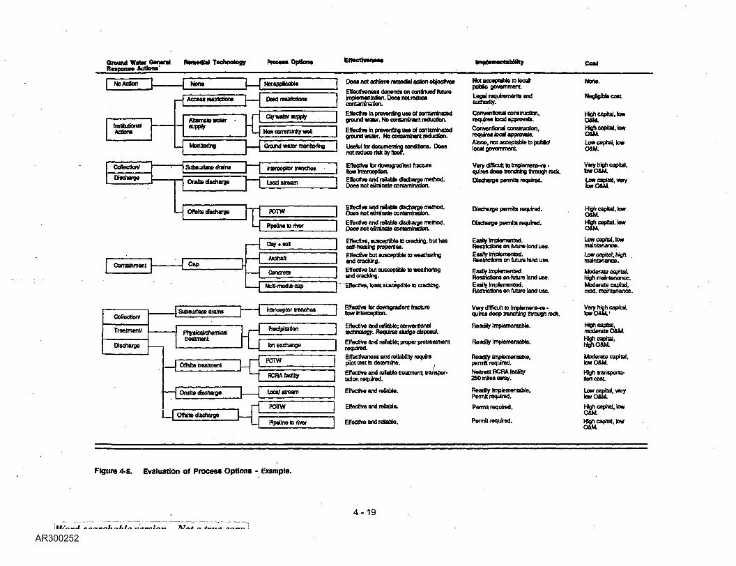
4.2.5 Evaluate Process Options
In the fourth step of alternative development, thetechnology processes considered to be implementableare evaluated in greater detail before selecting oneprocess to represent each technology type. Onerepresentative process is selected, if possible, for eachtechnology type to simplify the subsequent developmentand evaluation of alternatives without limiting flexibilityduring remedial design. The representative processprovides a basis for developing performance specificationsduring preliminary design; however, the specific processactually used to implement the remedial action at a sitemay not be selected until the remedial design phase. Insome cases more than one process option may beselected for a technology type. This may be done if twoor more processes are sufficiently -different in theirperformance that one would not adequately represent theother.
Process options are evaluated using the same criteria -effectiveness, implementability, and cost -that are usedto screen alternatives prior to the detailed analysis. Animportant distinction to make is that at
, this time these criteria are applied only to technologiesand the general response actions they are intended tosatisfy and not to the site as a whole. Furthermore, the
, evaluation should typically focus on effectiveness factorsat ' this stage with less effort directed at theimplementability and cost evaluation.
Because of the limited data on innovative technologies, itmay not be possible to evaluate these process options onthe same basis as other demonstrated technologies.Typically, if innovative technologies are judged to beimplementable they are retained for evaluation either as a"selected" process option (if available informationindicates that they will provide better treatment, fewer orless adverse effects, or lower costs than other options),or they will be "represented" by another process option ofthe same technology type. The evaluation of processoptions is illustrated in Figure 4-5 and discussed in moredetail below.
4.2.5.1 Effectiveness Evaluation
Specific technology processes that have been identifiedshould be evaluated further on their effectiveness relativeto other processes within the same technology type. Thisevaluation should focus on: (1) the potential effectivenessof process options in handling the estimated areas orvolumes of media and meeting the remediation goalsidentified in the remedial action objectives;6 (2) thepotential impacts to human health and the environmentduring the construction and implementation phase; and(3) how proven and reliable the process is with respect tothe contaminants and conditions at the site.
Information needed to evaluate the effectiveness oftechnology types for the different media includescontaminant type and concentration, the area or volumeof contaminated media, and, when appropriate, rates ofcollection of liquid or gaseous media. For some media itmay be necessary to conduct preliminary analyses orcollect additional site data to adequately evaluateeffectiveness. This is often the case for processes inwhich the rates of removal or collection and treatment areneeded for evaluation, such as for ground-waterextraction, surface-water collection and treatment, orsubsurface gas collection. In such cases, a limitedconceptual design of the process may need to bedeveloped, and modeling of the potential environmentaltransport mechanisms associated with their operationmay be undertaken. Typically, however, such analysesare conducted during the
6 The ability of some collection/removal systems, such as ground-water pumping, to sufficiently recover contaminated media forsubsequent treatment may also be assessed as part of thisevaluation.
4-16
Word-searchable version^- Not a true copy !

Ground Wttw CentralRoaponc* Actions
RmMdW Technology PFOCMC Opttonft Scrawling Comments*
No action
Deeds for property In the area of Influencewould Include restrictions on weds
Extension of existing municipal well systemto serve residents In the area o( Influence
New uncontamlnated wells to serve residentsIn the area of Influence
Ongoing monitoring of wells
cttonweV '////A Series of weds to extract contaminated, , , , , S f f / f A nmmd water
Cap
Clay end soU
Asphalt
Concrete
Multimedia cap
% \W*W
/Horizontal barrfera '
ground water
Injection web Inject uncomamlnatedwater to Increase flow to extraction wells
Perforated pipe In trenches backfilled withporous media to collect contaminated water
Extracted water discharged to stream on .tne site
Extracted water discharged to deep wenInjection systemExtracted water discharged to local POTWfor treatmentExtracted water discharged to river offslte
Compacted day covered with sou over areasof contamination
Spray application of a layer of asphalt overareas of contamination
Installation of a concrete slab over areasof contamination
day and synthetic membrane covered by souover areas of contamination
Trench around areas of contamination Is filledwith a soil (or cement) bentontte slurryPressure Injection of grout In a regular pattern.of drilled notes
Vibrating force to advance beams Into the groundwith Injection of slurry as beam Is withdrawn
Pressure Injection of grout at depth throughclosely spaced drBled holes
In conjunction with vertical barriers, Injectionof slurry In notched Injection holes
Required for consideration by NCP
Potentially applicable
Potentially applicable
Potentially applicable
Potentially appficafate
Not feasible for Intercepting contamtnantsIn fractured bedrockNot feasible for Intercepting contaminantsIn fractured bedrock
Potentially applicable
Potentially applicable
Deep aquifer not suitable for Injectionof oontomlnflnts
Potentially applicable
.Potentially applicable
PoterrtaHy applicable
PotonBally applicable
Potentially applicable
Potentially applicable
Not feasible because of very shallow depthto bedrock
Not effective because of fractured bedrock
Not feasible because of very sha9cw depthto bedrock
Not effective because of fractured bedrock
Not feasible because of very shallow depthto bedrock
Legend v ' -f ' ' - Technotojlea that are screened out
• Screening comment! may or may not be appfcabte to actual sits*.
Figure 4-4. An example of Initial screening of technologies and process options.
4-17

Ground Water GeneralRespone* Actions Re medal Technology Process Options Description Comments*
V See •ColtectkxVDIscharge* above
—'^{JJ J/S/S/Sj/SA Degradation of onjanto uslrig rricrcorganislrns' y*hl ////////A In an aerot* environment>LLf '///////\ Degradation of oroartes using mterooroanislrrwto*™?*? ///////A Inan anaerocfc eorironment
AJteratlon of chemical equilibria to reduce•olubHiy of t» contaminant*
'/SS/S///\ Mbdng large volumes of air with water In a'///////A peri wlunm to promote transfer of VOCsn air
"ration " ~///A Adsorption of contaminants onto activated carbon> s s ////\ by passing water through carbon column
LeganJ &~T~Z7\ • Teohnatogiei that m loaened OUL
•Scrssnlng comnem« nay or may not be ippnnim to uaua UK.
Figure 4-4. Continued. •
Use of high pressure to force water through amembrane leaving contaminants behindContaminated water ta passed through a resin bedwhere tons are exchanged between resin and waterCombustion In a horlzontaUy rotating cylinderdesigned for uniform heat transferWaste Injected into hot agitated bed of sand wherecombustion occursExtractBd ground water discharged ID local POTWfor treatmentExtractBd ground water discharged to ffscensedRCRA tedBty for treatment anoVor disposalSystem of Injection and extraction wells. Introducebacteria and nutrients to degrade contaminationSystem of weds to Inject air Into ground water toremove votaflles by air strippingDowngradtent trenches backfUted with activatedcarbon to remove contaminants from waterSystem of Injection wefts to Inject oxidizer suchas hydrogen peroxide to degrade contaminants
\ See Discharge under "Coflectlon// Discharge' above
)
Not feasible for Intercepting contaminantsin fractured bedrockNot feasible for intercepting contaminantsIn fractured bedrockPotonttaJyappScabte
Not applicable s> inorgarte contaminantsfound bi ground water at the siteNot applcabtelo Inorganic contaminantsbund In ground water at the sitePotanttaOy appDcaUe
Not applicable to Inorganic contaminantsfound In ground water at the siteNot applicable to Inorganic eontamlnartBfound In ground water at the siteContaminant concentrations too low fortreatment
Poteraaly applicable
Not appScable to Inorganic contaminantsfound In ground water at the siteNot applicable to Inorganic contaminantsfound in ground water at the site
^Potentially applicable
Potential applicable
Not feasible because of fractured bedrock
Not feasible because of fractured bedrock
Not feasible because of shallow depth to bedrock,fractured bedrockNot feasible because of fractured bedrock
Potenfiaty applicable
PotanflaSy applicable
Deep aquifer not suitable for Injectionof contaminated water
Potentially appfcabje
Word-searchable version —'i
4-18
around water aenara iisiaeoiai [aennoiogyResponse Actions'
HTW*M v/fxuin
NBAction ~1 1 None | 1 N« applicable
• — 1 Access restrictions 1 Daed restrictions
, 1 «_»_». - rl ayw.ttf.wlyInstitutional supply -J iActions L_j New community wet!
L Monitoring
Collection' — — j Subsurface drains
Obdmy* __j nmiH^Kht_0 — —I
L| Offslte discharge |
L
1—
Containment 1 C30 [•
Ground water monitoring
Interceptor trenches
Local stream
BiHHSii-naumTy c ,
1 Does not achieve rsmeoWactfai objectives r»* acceptable to locaV None.J puUc government
I lmptementationTDaM not reduce Legal requirements and Negligible cost,contamination. authority.
1 Effective In preventing use of eomambialod Conventional construction, High capital, lowJ ground water. No contaminant reduction. require* local approval. o&M.
1 Effective in preventing use of contamlralad Con£"! ^lruc5on' Hgh capital, lowJ ground water. No contaminant reduction. requires local approvals. O&M,1 . p Alone, not acceptable to 'pubic/ Low capital, low
not reduce risk by toeff.
] Effective for downgradfent fracture Very dttficutt to implemern-rs - Very high capital,J How Interception. quires deep trenching through rock. fawO&M.1 Effective and reliable dbcharge method. Discharge permits required. Low capital, veryj Does not eliminate contaminalion. tow O&M
I POTW
Pipeline to river
Qay + so!
Aiphatt
1 — 1 [_ Concrete
L-1 Subsurface drains 1
Mdti-media-cap
Interceptor trenches
TreatmenV phytk-nl hmrilffll J — 1 P"**"8*0"
Efecharga . L j ton exchange
._1 Offslte treatment 1 1H H-L
1 Onsto dfecharge J
!
POTW
RCRAfacffiiy
Local stTQSfn
POTW
Pipeline to river
i cuvuiwtuiuiiwauivuauuauviiiQUMu. Discharge permits required. High capital, low
1 Effective and reliable discharge method. Discharge permits required. Hgh capital, lowJ Does not eliminate contamination. O&M,
1 Effective, susceptible to cracking, but has Easfly Imptementad. Low capital, lowJ self-healing properties. Restrictions on future land use. maintenance.1 Effective but susceptible to weathering Easily Implemented. Low capital, highI and cracking. Restrictions on future land use. maintenance.I Effective but susceptible to weathering EaaTy Implemented. Moderate capital.J andcradung. Restrictions on future land use. Hgh maintenance.T~ 'Effective, least susceptible to cracMng. Easily Implemented. . Moderate capital,J Restrictions on future land use. mod. maintenance.
1 Effective tor downgradent fracture Very difficult to Implement-re - Very high capital.J flow Interception. quire* deep trenching through rock. lowO&M.'
Effective and reliable; conventional Readily Implementable. High capital,technology. Requires sbdge disposal. moderate O&M.
Effective and reliable; proper pretreatment Readily Implementable. MohO™L 'required. v ivwm.Effectiveness and reliability require Readily Implementable, Moderate capital,pilot test to determine. permit required. low O&M.Eflective and relaUa treatment; transpor- Nearest RCRA fadflly Hgh transpona-taflon required. 2SO mles away. Son cost
Effective and reliable. ReadHy Implementable, Low capital, veryPermit required. low O&M.
Effective and ratable. Permit required. High capital, lowO&M.
Effective and reliable. Permit required. High capital, lowO&M
Figure 4-s. Evaluation of Process Options - Example.
version -Not a trite copy I
4-19

later phases of the FS when alternatives are refined andevaluated on a sitewide basis.
If modeling of transport processes is undertaken duringthe alternative development and screening phases of theFS to evaluate removal or collection technologies, and ifmany contaminants are present at the site, it may benecessary to identify indicator chemicals, as is oftendone for the baseline risk assessments, to simplify theanalysis. Typically, indicator chemicals are selected onthe basis of their usefulness in evaluating potential effectson human health and the environment. Commonlyselected indicator chemicals include those that are highlymobile and highly toxic.
4.2.5.2 Implementability Evaluation
Implementability encompasses both the technical andadministrative feasibility of implementing a technologyprocess. As discussed in Section 4.2.4, technicalimplementability is used as an initial screen of technologytypes and process options to eliminate those that areclearly ineffective or unworkable at a site. Therefore, thissubsequent, more detailed evaluation of process optionsplaces greater emphasis on the institutional aspects ofimplementability, such as the ability to obtain necessarypermits for offsite actions, the availability of treatment,storage, and disposal services (including capacity), andthe availability of necessary equipment and skilledworkers to implement the technology.
4.2.5.3 Cost Evaluation
Cost plays a limited role in the screening of processoptions. Relative capital and O&M costs are used ratherthan detailed estimates. At this stage in the process, thecost analysis is made on the basis of engineeringjudgment, and each process is evaluated as to whethercosts are high, low, or medium relative to other processoptions in the same technology type. As discussed inSection 4.3, the greatest cost consequences in siteremediation are usually associated with the degree towhich different general technology types (i.e.,containment, treatment, excavation, etc.) are used. Usingdifferent process options within a technology type usuallyhas a less significant effect on cost than does the use ofdifferent technology types.
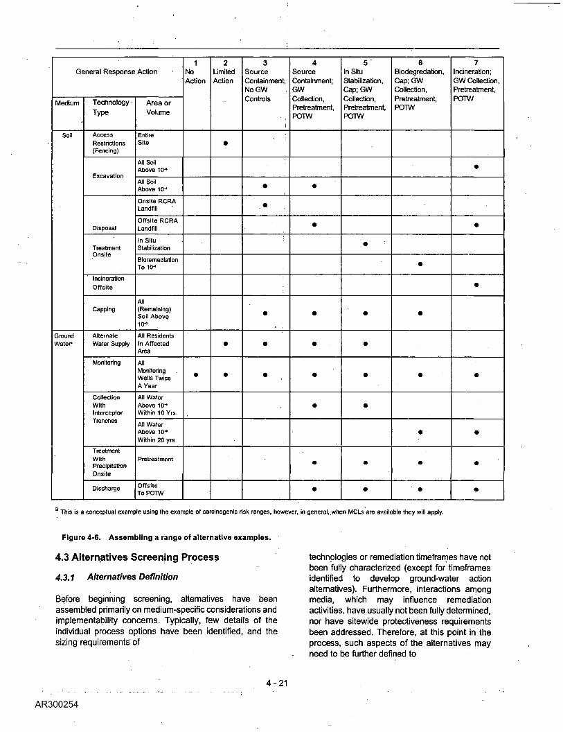
4.2.6 Assemble Alternatives
In assembling alternatives, general response actions andthe process options chosen to represent the varioustechnology types for each medium or operable unit arecombined to form alternatives for the site as a whole. Asdiscussed in Section 4.1.2.1, appropriate treatment andcontainment options should
be developed. To assemble alternatives, general responseactions should be combined using different technologytypes and different volumes of media and/or areas of thesite. Often more than one general response action isapplied to each medium. For example, alternatives forremediating soil contamination will depend on the typeand distribution of contaminants and may includeincineration of soil from some portions of the site andcapping of others.
For sites at which interactions among media are notsignificant (i.e., source control actions will not affectground-water or surface-water responses) the combinationof medium-specific actions into site wide alternatives canbe made later in the FS process, either after alternativeshave been screened or prior to conducting thecomparative analysis of alternatives. For example, ifmedia interactions are not of concern, an FS mightdescribe three source control options, three soilremediation options, and four ground-water remediationoptions, (instead of developing numerous comprehensivesitewide alternatives). Although this approach permitsgreater flexibility in developing alternatives and simplifiesthe analyses of sitewide alternatives, it may involve
, greater effort in developing and analyzing medium-specificoptions.
Figure 4-6 illustrates how general response actions maybe combined to form a range of sitewide alternatives. Forthis relatively simple example, the two media of interestare soil and ground water. The range of alternatives
i developed include a no-action alternative (alternative 1); a. limited action alternative (alternative 2); sourcecontainment options with and without ground watertreatment (alternatives 3 and 4); and three alternativesthat employ various levels of source treatment, withground-water collection and treatment (alternatives 5, 6,and 7).
Although not shown in this example, a description of eachalternative should be included in the FS report. For thealternatives presented in Figure 4-6, such descriptionswould include the locations of areas to be excavated orcontained, the approximate volumes of soil and/or groundwater to be excavated and collected, the approximatelocations of interceptor trenches, the locations of potentialcity water supply hook-ups, the locations of connectionsto the local publicly owned treatment works (POTW),management options for treatment residuals, and anyother information needed to adequately describe thealternative and document the logic behind the assemblyof general response actions into specific remedial actionalternatives. In describing alternatives, it may be useful tonote those process options that were not screened outand that are represented by those described in thealternative.
4-20
Word-searchable_version- Not a true copy
General Response Action
Medium
Soil
Groundwater-
Technology •
Type
AccessRestrictions(Fencing)
Excavation
Disposal
TreatmentOnsite
IncinerationOffsite
Capping
AlternateWater Supply
Monitoring
CollectionWithInterceptorTrenches
TreatmentWithPrecipitationOnsite
Discharge
Area or
Volume
EntireSite
All SoilAbove 10-*
All SoilAbove 10-"
Onsite RCRALandfill
Offsite RCRALandfill
In SituStabilization
BioremediationTola4
All(Remaining)Soil Above10-"
All ResidentsIn AffectedArea
AllMonitoringWells TwiceA Year
All WaterAbove 10-*Within 10 Yrs.
All WaterAbove 1O*Within 20 yrs
Pretreatment
OffsiteToPOTW
1.NoAction
•
2LimitedAction
•
•
•
3SourceContainment;NoGW .
Controls '.
•
•
•
•
•
4SourceContainment;GWCollection,Pretreatment,POTW
•
•
•
•
•
•
•
•
5In SituStabilization,Cap;GWCollection,Pretreatment,POTW
•
•
•
•
•
•
•
6Biodegredation,Cap;GWCollection,Pretreatment,POTW
•
• •
•
•
•
' •
7Incineration;GW Collection,Pretreatment,POTW
•
•
•
•
•
•
•
This is a conceptual example using the example of carcinogenic risk ranges, however, in general, when MCLs are available they will apply.
Figure 4-6. Assembling a range of alternative examples.
4.3 Alternatives Screening Process
4.3.1 Alternatives Definition
Before beginning screening, alternatives have beenassembled primarily on medium-specific considerations andimplementability concerns. Typically, few details of theindividual process options have been identified, and thesizing requirements of
technologies or remediation timeframes have notbeen fully characterized (except for timeframesidentified to develop ground-water actionalternatives). Furthermore, interactions amongmedia, which may influence remediationactivities, have usually not been fully determined,nor have sitewide protectiveness requirementsbeen addressed. Therefore, at this point in theprocess, such aspects of the alternatives mayneed to be further defined to
4-21
^ord-seqrchable version-Not a true copy \

form the basis for evaluating and comparing thealternatives before their screening.
4.3.1.1 Specific Objectives
Alternatives are initially developed and assembled to meeta set of remedial action objectives for each medium ofinterest. During screening, the assembled alternativesshould be evaluated to ensure that they protect humanhealth and the environment from each potential pathwayof concern at the site or those areas of the site beingaddressed as part of an operable unit. If more than onepathway is present, such as inhalation of airbornecontaminants and ingestion of contaminants in groundwater, the overall risk level to receptors should beevaluated. If it is found that.-an alternative is not fullyprotective, a reduction in exposure levels for one or moremedia will need to be made to attain an acceptable risklevel.
In refining alternatives, it is important to note thatprotectiveness is achieved by reducing exposures toacceptable levels, but achieving these reductions inexposures may not always be possible by actuallycleaning up a specific medium to these same levels. Forexample, protection of human health at a site may requirethat concentrations of contaminants in drinking water bereduced to levels that could not reasonably be achievedfor the water supply aqujfer; thus, protection could beprovided by preventing exposures with the use of awellhead treatment system. The critical selection of howrisk reductions are to be achieved is part of the riskmanagement decisionmaking process.
4.3.1.2 Define Media and Process Options
Alternatives should be defined to provide sufficientquantitative information to allow differentiation amongalternatives with . respect to effectiveness,implementability, and cost. Parameters that often requireadditional refinement include the extent or volume ofcontaminated material and the size of major technologyand process options.
Refinement of volumes or areas of contaminated media isimportant at some sites at which ongoing releases fromthe source (or contaminated soils) significantly affectcontaminant levels in other media (e.g., ground water)because such interactions may not have been addressedwhen alternatives were initially developed by groupingmedium-specific response actions. If interactions amongmedia appear to be important at a site, the effect ofsource control actions on the remediation levels or timeframes for other media should be evaluated.
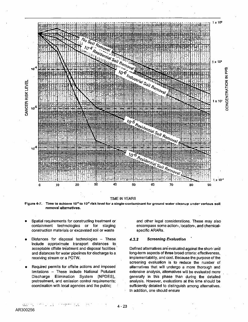
Figure 4-7 provides an example of such an analysis inwhich volatile organics in soil are migrating into an
underlying aquifer composed of unconsolidated materials.Using a model of transport processes at the site, theeffect of different soil removal actions on ground-waterremediation (using a specified extraction scheme) couldbe estimated. In this example, development of alternativesthat consider ground water actions independent of soilremoval (i.e., the no-soil-removal scenario) could result inunderestimating the achievable remediation level oroverestimating the time frame for ground-wateriremediation. This could result in an overestimation of theextraction and treatment requirements for technologyprocesses for ground water. By evaluating soil and groundwater actions together, the rates and volumes of groundwater extraction to achieve the target remediation levelscan be refined more accurately.
After the alternatives have been refined with respect tovolumes of media, the technology process options needto be defined more fully with respect to their effectiveness,
i implementability, and cost such that differences amongalternatives can be identified. The following information
. should be developed, as appropriate, for the varioustechnology processes used in an alternative:
i
• Size and configuration of onsite extraction andtreatment systems or containment structures - Formedia contaminated with several hazardoussubstances, it may be necessary to first determine
i which contaminant(s) impose the greatest treatmentrequirements; then size or configure accordingly.Similarly, for ground-water extraction technologies atsites with multiple ground-water contaminants, it maybe necessary to evaluate which compounds imposethe greatest limits on extraction technologies, either
' because of their chemical/physical characteristics,concentration, or distribution in ground water.
• Time frame in which treatment, containment, orremoval goals can be achieved - The remediation
, time frame is often interdependent on the size of atreatment system or configuration of a ground-waterextraction system. The time frame may bedetermined on the basis of specific remediation goals(e.g., attaining ground-water remediation goals in 10years), in which case the technology is sized andconfigured to achieve this; the time frame may also
• be influenced by technological limitations (such asmaximum size consideration, performancecapabilities, and/or availability of adequate treatmentsystems or disposal capacity).
• Rates or flows of treatment - These will also influencethe sizing of technologies and time frame withinwhich remediation can be achieved.
4-22
Word-searchable version-^Not^a true'copy_j
-T 1X10³
LU
cccc
^L-:::: - 1 x 10-'70 80 90
TIME IN YEARSFigure 4-7. Time to achieve 10"" to 10"" risk level for a single-contaminant for ground water cleanup under various soil
removal alternatives.
Spatial requirements for constructing treatment orcontainment technologies or for stagingconstruction materials or excavated soil or waste
Distances for disposal technologies - Theseinclude approximate transport distances toacceptable offsite treatment and disposal facilitiesand distances for water pipelines for discharge to areceiving stream or a POTW.
Required permits for offsite actions and imposedlimitations - These include National PollutantDischarge Elimination System (NPDES),pretreatment, and emission control requirements;coordination with local agencies and the public;
and other legal considerations. These may alsoencompass some action-, location-, and chemical-specific ARARs.
4.3.2 Screening Evaluation
Defined alternatives are evaluated against the short- andlong-term aspects of three broad criteria: effectiveness,implementability, and cost. Because the purpose of thescreening evaluation is to reduce the number ofalternatives that will undergo a more thorough andextensive analysis, alternatives will be evaluated moregenerally in this phase than during the detailedanalysis. However, evaluations at this time should besufficiently detailed to distinguish among alternatives.In addition, one should ensure
Word-searchable version —Not a true cqpy\ 4-23

that the alternatives are being compared on anequivalent basis (i.e., definitions of treatmentalternatives are approximately at the same level ofdetail to allow preparation of comparable costestimates).
Initially, specific technologies or process options wereevaluated primarily on the basis of whether or not theycould meet a particular remedial action objective.During alternative screening, the entire alternative isevaluated as to its effectiveness, implementability, andcost.
During the detailed analysis, the alternatives will beevaluated against nine specific criteria and theirindividual factors rather than the general criteria used inscreening. Therefore, individuals conducting the FSshould be familiar with the nine criteria (see Section6.2.2) at the time of screening to better understand thedirection that the analysis will be taking. Therelationship between the screening criteria and the nineevaluation criteria is conceptually illustrated in Figure4-8.
It is also important to note that comparisons duringscreening are usually made between similar alternatives(the most promising of which is carried forward forfurther analysis); whereas, comparisons during thedetailed analysis will differentiate across the entirerange of alternatives. The criteria used for screening aredescribed in the following sections.
4.3.2.1 Effectiveness Evaluation
A key aspect of the screening evaluation is theeffectiveness of each alternative in protecting humanhealth and the environment. Each alternative should beevaluated as to its effectiveness in providing protectionand the reductions in toxicity, mobility, or volume thatit will achieve. Both short- and long-term components ofeffectiveness should be evaluated; short-term referringto the construction and implementation period, andlong-term referring to the period after the remedialaction is complete. Reduction of toxicity, mobility, orvolume refers to changes in one or more characteristicsof the hazardous substances or contaminated media bythe use of treatment that decreases the inherent threatsor risks associated with the hazardous material.
4.3.2.2 Implementability Evaluation
Implementability, as a measure of both the technicaland administrative feasibility of constructing, operating,and maintaining a remedial action alternative, is usedduring screening to evaluate the combinations ofprocess options with respect to conditions at a specificsite. Technical feasibility refers to the ability toconstruct, reliably operate, and meettechnology-specific regulations for process options untila remedial action is complete; it also includesoperation, maintenance, replacement, and monitoring
of technical components of an alternative, if required,into the future after the remedial action is complete.Administrative feasibility refers to the ability to obtainapprovals from other offices and agencies, theavailability of treatment, storage, and disposal servicesand capacity, and the requirements for, and availabilityof, specific equipment and technical specialists.
The determination that an alternative is not technicallyfeasible and is not available will usually preclude it fromfurther consideration unless steps can be taken tochange the conditions responsible for thedetermination. Typically, this type of "fatal flaw" wouldhave been identified during technology screening, andthe infeasible alternative would not have beenassembled. Negative factors affecting administrativefeasibility will normally involve coordination steps tolessen the negative aspects of the alternative but willnot necessarily eliminate an alternative fromconsideration.
4.3.2.3 Cost Evaluation
Typically, alternatives will have been defined wellenough before screening that some estimates of costare available for comparisons among alternatives.However, because uncertainties associated with thedefinition of alternatives often remain, it may not bepracticable to define the costs of alternatives with theaccuracy desired for the detailed analysis (i.e., +50percent to -30 percent).
Absolute accuracy of cost estimates during screeningis not essential. The focus should be to makecomparative estimates for alternatives with relativeaccuracy so that cost decisions among alternatives willbe sustained as the accuracy of cost estimatesimproves beyond the screening process. Theprocedures used to develop cost estimates foralternative screening are similar to those used for thedetailed analysis; the only differences would be in thedegree of alternative refinement and in the degree towhich cost components are developed.
Cost estimates for screening alternatives typically willbe based on a variety of cost-estimating data. Bases forscreening cost estimates may include cost curves,generic unit costs, vendor information, conventionalcost-estimating guides, and prior similar estimates asmodified by site-specific information.
Prior estimates, site-cost experience, and goodengineering judgments are needed to identify thoseunique items in each alternative that will control thesecomparative estimates. Cost estimates for itemscommon to all alternatives or indirect costs(engineering, financial, supervision, outside contractorsupport, contingencies) do not normally warrant
4-24
Word-searchableversion -Not a true copy'.

:SSCREENINGCRITERIA
NINE EVALUATIONCRITERIA
ROLE OF CRITERIA DURINGREMEDY SELECTION
*lI
I:
cn
Implementability
Overall Protection of Human Healthand Environment
Compliance with ARABS
Long-term Effectiveness and Permanance
Reductions In Toxlcity, Mobility, andVolume Through Treatment
Short-term Effectiveness
Cost Cost
Threshold" Factors
"Primary Balancing" Factors
Stats Acceptance
Community Acceptance
"Modifying" Considerations
Figure 4-8. Relationship of Screening Criteria to the Nine Evaluation Criteria.

substantial effort during the alternative screening phase.
Both capital and O&M costs should be considered, whereappropriate, during the screening of alternatives. Theevaluation should include those O&M costs that will beincurred for as long as necessary, even after the initialremedial action is complete. In addition, potential futureremedial action costs should be considered duringalternative screening to the extent they can be defined.Present worth analyses should be used during alternativescreening to evaluate expenditures that occur overdifferent time periods. By discounting all costs to acommon base year, the costs for different remedial actionalternatives can be compared on the basis of a singlefigure for each alternative.
A more detailed discussion of cost evaluations ispresented in Chapter 6.
4.3.2.4 Innovative Technologies
Technologies are classified as innovative if they aredeveloped fully but lack sufficient cost or performancedata for routine use at Superfund sites. In many cases, itwill not be possible to evaluate alternatives incorporatinginnovative technologies on the same basis as availabletechnologies, because insufficient data exist on innovativetechnologies. If treatability testing is being considered tobetter evaluate an innovative technology, the decision toconduct a test should be made as early in the process aspossible to avoid delays in the RI/FS schedule.
Innovative technologies would normally be carried throughthe screening phase if there were reason to believe thatthe innovative technology would offer significantadvantages. These advantages may be in the form ofbetter treatment performance or implementability, feweradverse impacts than other available approaches, or lowercosts for similar levels of performance. A "reasonablebelief exists if indications from other full-scaleapplications under similar circumstances or frombench-scale or pilot-scale treatability testing supports theexpected advantages.
4.3.3 Alternative Screening
4.3.3.1 Guidelines for Screening
Alternatives with the most favorable composite evaluationof all factors should be retained for further considerationduring the.detailed analysis. Alternatives selected forfurther evaluation should, where practicable, preserve therange of treatment and containment technologies initiallydeveloped. It is not a requirement that the entire range ofalternatives originally developed be preserved if allalternatives in
a portion of the range do not represent distinct viableoptions.
The target number of alternatives to be carried throughscreening should be set by the project manager and thelead agency on a site-specific basis. It is expected thatthe typical target number of alternatives carried throughscreening (including containment and no-actionalternatives) usually should not exceed 10. Feweralternatives should be carried through screening, ifpossible, while adequately preserving the range ofremedies. If the alternatives being screened are stillmedium-specific and do not address the entire site oroperable unit, the number of alternatives retained for eachspecific medium should be considerably less than 10.
4.3.3.2 Selection of Alternatives for DetailedAnalysis
i Once the evaluation has been conducted for each of thealternatives, the lead agency and its contractor shouldmeet with the support agency to discuss each of thealternatives being considered. This meeting does notcorrespond to a formal quality control review stage but
: provides the lead agency and its contractor with inputfrom the support agency and serves as a forum forupdating the support agency with the current direction ofthe FS.
The alternatives recommended for further considerationshould be agreed upon at this meeting so thatdocumentation of the results of alternative screening iscomplete; any additional investigations that may benecessary are identified; and the detailed analysis cancommence.
Unselected alternatives may be reconsidered at a laterstep in the detailed analysis if similar retained alternativescontinue to be evaluated favorably or if information isdeveloped that identifies an additional advantage notpreviously apparent. This provides the flexibility to doublecheck a previous decision or to review variations ofalternatives being considered (e.g., consideration of othersimilar process options). However, it is expected thatunder most circumstances, once an alternative isscreened out it will not be reconsidered for selection.
4.3.3.3 Post-screening Tasks
The completion of the screening process leads directlyinto the detailed analysis and may serve to identifyadditional investigations that may be needed toadequately evaluate alternatives. To ensure a smoothtransition from the screening of alternatives to the detailedanalysis, it will be necessary to identify and beginverifying action-specific ARARs and initiate treatabilitytesting (if not done previously) and additional sitecharacterization, as appropriate.
4-26
Word-searchable^versiott—Not a true cgpy\

Although the consideration of action-specific ARARsbegins earlier as process options are combined, theidentification of action-specific ARARs'will need to bemore definitive as the alternatives become better defined.At the conclusion of screening, sufficient informationshould exist on the technologies and the most probableconfigurations of technologies so that the lead agencyand support agency can better define and agree onaction-specific ARARs. As with chemical-specificARARs, action-specific ARARs should include all Federalrequirements and any State requirements that either aremore stringent than Federal ARARs or specifyrequirements where no Federal ARARs exist.
Once the field of alternatives has been narrowed, thetechnology processes of greatest interest can beidentified. At this point, the need for treatability tests (ifnot identified earlier) can be determined for processoptions that will require additional data for- detailedanalysis. Although the results of treatability testing maynot be used until the detailed analysis, they should beinitiated as early in the process as possible to minimizeany potential delays on the FS schedule. The type andscope of treatability tests depends on the expected datarequirements for detailed analysis of alternatives. Factorsinvolved in determining the need for and scope oftreatability studies are discussed in Chapter 5.
In some cases, the need for additional sitecharacterization may also be identified during thescreening phase. Because the nature and extent ofcontamination is usually well defined at this time,additional field investigations should be conducted only tobetter define the effect of site conditions on theperformance of the technology processes of greatestinterest.
4.4 Community Relations DuringAlternative Development andScreening
The community relations activities implemented for sitecharacterization may also be appropriate during thedevelopment of alternatives. Activities focus on providinginformation to the community concerning the developmentand screening of remedial alternatives and obtainingfeedback on community interests and concerns'associated with such alternatives. Community relationsactivities should be site- and community-specific and areusually stipulated in the community relations plan that isprepared during scoping activities. Community relationsactivities during the development of alternatives mayinclude, but are not limited to, a fact sheet describingalternatives identified as potentially feasible, a workshoppresenting citizens with the Agency's considerations fordeveloping alternatives, briefings for local officials andconcerned citizens on alternatives under consideration, a
small group meeting for citizens involved with the site,and news releases describing technologies beingevaluated. It is important to note that public interesttypically increases as the feasibility study progresses;and that the technical adequacy of a remedy does notensure community acceptance. Therefore, the communityrelations activities should be planned and conducted toaddress such interest and potential concerns.
If alternatives are being developed concurrently with the Rlsite characterization, information on the screening oftechnologies and remedial alternative development shouldbe included in public information materials and activitiesprepared during site characterization. If alternatives aredeveloped after site characterization, additionalcommunity relations activities should be conducted. Ingeneral, community relations activities during alternativedevelopment and screening are most appropriate ifcitizens are significantly concerned over site conditionsand RI/FS activities that are being implemented at thesite. The level of effort for community relations at thisphase should be described in the community relationsplan.
4.5 Reporting and CommunicationDuring Alternative Development andScreening
Although no formal report preparation is required duringthe development and screening of alternatives (exceptwhatever routine administrative and project managementtracking methods have been designated for use by thelead agency and its contractor(s))7, some form of writtendocumentation of the methods, rationale, and results ofalternative screening (e.g., graphical representationsimilar to Figures 4-5 and 4-6 or a technicalmemorandum) needs to be provided to the lead andsupport agencies. If a technical memorandum is prepared,it can serve as the basis for later development of thechapter(s) in the FS report that discusses thedevelopment and screening of alternatives.
Communication among the lead and support agenciesand their contractor(s) is very important to obtain inputand agreement on the technologies or processes andalternatives considered for implementation at the site. Asshown in Table 4-2, communication should occur tofacilitate the initial screening of technologies and processoptions, to agree on what additional site data may beneeded, and to gain input and agreement on the choice ofrepresentative processes and combinations to be
7 The RPM may require a written deliverable from the PRPs duringalternative development and screening for a PRP-lead RI/FS.
4 r 2 7
true copyl
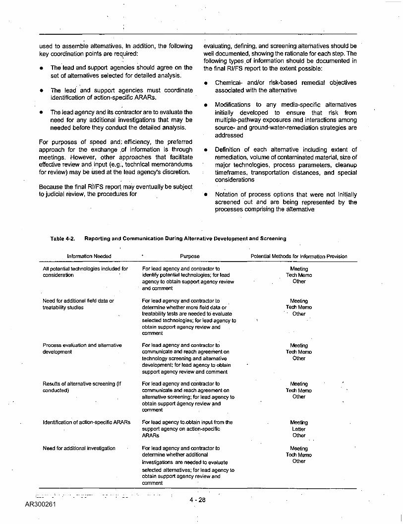
used to assemble alternatives. In addition, the followingkey coordination points are required:
• The lead and support agencies should agree on theset of alternatives selected for detailed analysis.
• The lead and support agencies must coordinateidentification of action-specific ARARs.
• The lead agency and its contractor are to evaluate theneed for any additional investigations that may beneeded before they conduct the detailed analysis.
For purposes of speed and; efficiency, the preferredapproach for the exchange ,of information is throughmeetings. However, other approaches that facilitateeffective review and input (e.g:, technical memorandumsfor review) may be used at the lead agency's discretion.
Because the final RI/FS report may eventually be subjectto judicial review, the procedures for
evaluating, defining, and screening alternatives should bewell documented, showing the rationale for each step. Thefollowing types of information should be documented inthe final RI/FS report to the extent possible:
• Chemical- and/or risk-based remedial objectivesassociated with the alternative
• Modifications to any media-specific alternativesinitially developed to ensure that risk frommultiple-pathway exposures and interactions amongsource- and ground-water-remediation strategies areaddressed
• Definition of each alternative including extent ofremediation, volume of contaminated material, size ofmajor technologies, process parameters, cleanuptimeframes, transportation distances, and specialconsiderations
• Notation of process options that were not initiallyscreened out and are being represented by theprocesses comprising the alternative
Table 4-2. Reporting and Communication During Alternative Development and Screening
Information Needed Purpose Potential Methods for Information Provision
All potential technologies included forconsideration
Need for additional field data ortreatability studies
Process evaluation and alternativedevelopment
Results of alternative screening (ifconducted)
Identification of action-specific ARARs
Need for additional investigation
For lead agency and contractor toidentify potential technologies; for leadagency to obtain support agency reviewand comment
For lead agency and contractor todetermine whether more field data ortreatability tests are needed to evaluateselected technologies; for lead agency toobtain support agency review andcomment
For lead agency and contractor tocommunicate and reach agreement ontechnology screening and alternativedevelopment; for lead agency to obtainsupport agency review and comment
For lead agency and contractor tocommunicate and reach agreement onalternative screening; for lead agency toobtain support agency review andcomment
For lead agency to obtain input from thesupport agency on action-specificARARs
For lead agency and contractor todetermine whether additionalinvestigations are needed to evaluateselected alternatives; for lead agency toobtain support agency review andcomment
MeetingTech Memo
Other
MeetingTech Memo
Other
MeetingTech Memo
Other
MeetingTech Memo
Other
MeetingLetterOther
MeetingTech Memo
Other
Word-searchable version — Not a true copy 4 - 28