evaluation of the deformation behavior of nylon materials used in ballistic applications
TRANSCRIPT

AD-A171 281
US ARMY
MATERIEL
COMMAND CONTRACT REPORT BRL-CR-554 DTlC
S :LECTEDAUU 19 "D
EVALUATION OF THE DEFORMATION BEHAVIOR
OF NYLON MATERIALS USED INBALLISTIC APPLICATIONS
Battelle Pacific Northwest LaboratoryP.O. Box 999
Richland, WA 99352
0..
June 1986
t- APMROVED FOR PUBULI RELEASE; DISTRIBUTION UNUMITED.
US ARMY BALLISTIC RESEARCH LABORATORYABERDEEN PROVING GROUND, MARYLAND
"• "" " " A c)
-
k 0P- -~v vr ~rW% ~*~ %'

Destroy this report when it is no longer needed.Do not return it to the originator.
Additional copies of this report may be obtainedfrom the National Technical Information Service,U. S. Department of Commerce, Springfield, Virginia22161.
The findings in'this report are not to be construed as an officialDepartment of the Army position, unless so designated by otherauthorized documents.
The use of trade names or manufacturers' names in this reportdoes not constitute indorsement of any commercial product.

UNCLASSIFIEDSECURITY CLASSIFICATIO4 OF THIS PAGE (Mion Dbte Entered)
REPORT DOCUMENTATION PAGE 1 READ INSTRUCTIONSREPORTDOCUMENTATIONPAGEBEFORE COMPLETING FORM
I REPORT NUMBER 2. GOVT ACCESSION NO. 3 RECIPIENT'S CATALOG NUMBER
CONTRACT REPORT BRL-CR- 554 ý _ 4. -
4. TITLE (Mid Subtitle) i TYPE OF REPORT a PERIOD COVERED
EVALUATION OF THE DEFORMATION BEHAVIOR OF NYLONMATERIALS USED IN BALLISTIC APPLICATIONS
6 PERFOR,*ING ORG. REPORT NUMBER
7. AUTHOR(e) 11. CONTRACT OR GRANT NUMBER(.)
, Mark T. SmithEdwmrd M. Pattrm
9. PERFORMING ORGANIZATION NAME AND ADDRESS 10. PROGRAM ELEMENT. PROJECT. TASK
Battelle Pacific Northwest Laboratory- AREA A WORK UNIT NUMBERS
P.O. Box 999 1L162618AH80Richland, WA 99352II. CONTROLLING OFFICE NAME AND ADDRESS 12. REPORT DATE
US Army Ballistic Research Laboratory June 1986ATTN: SLCBR-DD-T 1). NUMBER OF PAGES
Aberdeen Proving Ground, MD 21005-5066 35I4 MONITORING I.GENCY NAME A ADDRESS(II dlflerent from Confrollin& Office) IS. SECURITY CLASS. (of this report)
UNCLASSIFIED1I[,a1 DECL ASSIFIrC ATI ON/OOWN GRADING
SCHEDULE
I6 OISTRIPI)TION STATEMENT (of thle Report)
Approved for public release, distribution unlimited.
17. DISTRIBUTION STATEMENT (of he ebesrect Mntered in Block 20. if different from .eport)
IS. SUPPLEMENTARY NOTES
IS. KEY *OROS (Continue on reverese ide if neceeew'y Mid Identify by blork number)
Nylon ObturatorMechanical Properties Compression TestsStrcss-Straln Behavior Elastic Modulus
Yi'ld Point
20 AVSTrACT (Corana on rer, ee. .td If nv wory & idefslift by block number)
The deformation behavior of two nylon 6/6 (Zytel 101) materials under variouscompressive loading conditions was evaluated in support of Phase III of theProjectile Foundation Moment Generation project.
(over)
DO I 147 OITIOW OF t NOV6 IS OSOLETF IUJCLASSIFIED
SECURITY CLASSIFICATION OF THIS -A-.E (When Dore Pnteoe,)

UNCLASSIFIEDSECURITY CLASSIFICATION Of THIS PAOE(Whan Date AntateQ
20. Abstract (cont'd)
Extruded and centrifugally cast nylon, representative of current projectileobturator band materials, were tested in compression at static and dynamicloading rates. The high strain rates associated with the dynamic compressiontest (2600 in./in./min) resulted in significantly higher yield and compressivestrengths, but only a minimal (8%) increase In elastic modulus.
Elastic constants for both materials were measured using the ultrasonic pulse-echo method, and the results show good agreement with mechanical test values.However, the experimentally determined elastic modulus values for bothmaterials were found to be considerably higher than published book values.
The effects of an elevated confining pressure on compressive deformationbehavior were evaluated using a compressive load frame equipped with ahydrostatic fluid chamber. Although test results obtained at a confiningpressure of 7000 psi indicate that the extruded nylon yield behaviorapproaches that predicted by Von Mises' yield criterion, improvements in
displacement instrumentation would be necessary before these ddLa could becompared directly with other mechanical test results.
It is concluded that a dynamic compression test inI which the specimen isexposed to a hydrostatic confining pressure would be required to fullysimulate the deformation response of obturator materials under ballistic
launch conditions-...
0
UNCLASSIFIED
%ECURITY CLASSIFiCATION OF THIS PAGE110- t).(. Fs,.,,d'

TAIKit OF ON€rnTS
PACE
List of Illustrations ... .............................................. 5
1.0 INTRODUCTION .......... ............. # ................. ............ 7
2.0 ANALYSIS OF OBTURATOR STRESS STATE .............................. 8
3.0 EXPERIMENTAL TEST PROGRAM ....................... 9
3.1 EXPERIMENTAL PROCEDURE ......... . ......... ... * ...... o ........ 9
3.1.1 Static Compression Test .............................. 9
3.1.2 Ultrasonic Determination of ElasticConstants ......... ... ...... ............ ..... ........ 10
3.1.3 Dynamic Compression Testing .......................... 10
3.1.4 Compression Tests on Nylon at ElevatedConfining Pressures .............. .................... 11
4.0 RESULTS AND DISCUSSION ............... ..... . .......... 14
4.1 STATIC COMPRESSIVE PROPERTIES .......................... 14
4.2 DYNAMIC COMPRESSIVE PROPERTIES ......................... 16
4.3 HYDROSTATIC COMPRESSIVE PROPERTIES .................... 19
5.0 CONCLUSIONS AND RECOMMENDATIONS ............................. 21
REFERENCES ....................................................... 22
APPENDIX: Calculation of Material Elastic ConstantsFrom Measured ULtrasonic Wave Velocities .............. 23
DIST UTION LIST .................................. 25

LIST OF ILUISTRATIONS
Figure Page
I Two-Dimensional Obturator Finite-Element Mesh ................... 8
2 !95drostatic Compression Fixture with SpecimenInstalled ............................................ .......... 11
3 Instrumented Hydrostatic Compression Assembly .................. i2
4 Hydrostatic Test System .............................. .. ........ 13
5 Static and Dynamic Stress/Strain Curves ......................... 18
6 Hydrostatic Compressive Stress/Strain Curve ..................... 20
I4

1.0 INTRODUCTION
Modern kinetic energy projectil's utilize nylon or nylon-based polymer materials to provide in-bore contact between thegun barrel tube and sabot components. In addition, the rear-most nylon band, known as the obturator, must provide a sealagainst the high propellant gas pressures used to launch thesahot/penetrator system.
Design requirements for the obturator band specify the useof DuPont Zytel 101 nylon or nylon-filled material meeting IMil-M-20693. This material, which is a nylon 6/6 composition,' canbe produced in tubular form by centrifugal casting or pressureextrusion processes. The tubular product form is then cut andmachined to specific dimensions required for the obturatordesign.
Although conventional material properties such as tensileand compressive strengths, flexural modulus, elongatio I, anddensity are available in the literature for Zytel 101,1 suchproperty values are of limited usefulness for modeling of in-bore dynamic behavior of nylon obturator bands. The inadequacyof conventional test methods to predict material behavior underballistic loading conditions appears to be due primarily to thedependence of polymer deformation response on loading or strainrate. For semicrystalline polymers such as Zytel 101, increasesin deformation rate can be expected to result in higher valuesof elastic modulus and yield strength due to anelasticeffects. Standard ASTM procedures for tensile and compressivetesting of polymeric materials specify strain rates of 0.01 to0.10 in./in./min, while ballistic launch conditions typicallyimpose strain rates 3 to 5 orders of magnitude higher.
The major objective pf this study, conducted by PacificNorthwest Laboratory (PNL)ýa) for the Ballistic Research Labora-tory (BRL), was therefore to investigate and characterize thebehavior of Zytel 101 nylon under test conditions that morenearly duplicate ballistic loading conditions. The experimentaltest plan, in addition, had the objective of determining thedependence of material properties on processing methods andspecimen orientation. n C I C
Copy
0
(a) Operated for the U.S. Department of Energy by Battelle ..........--Memorial Institute under Contract OE-AC06-76RLO 1830.
y Codes
" [ D 1 .t . • ' ic /a r
A-it

2.0 ANALYSIS OF OBTURATOR STRESS STATE
A twvo-dimensional, axisymmetric, finite-element model of anXM829 obturator band tinder ballistic loading conditions was usedto determine the magnitude and state of stress for a typicalvalue of base gas pressure. Because the obturator material isconstrained between the sabot and the gun barrel tube in therAlial direction, application of a gas surface pressure in thed:r'ection of the gun barrel axis produces a triaxial compressivestress state. A two-dimensional illustration of the obturatorband finite-element mesh is shown in Figure 1. Calculated val-ues for the three principal stresses, Sx, S., Sz, and the shearstress -c% indicate that a triaxial comprdssive stress with avery low hear stress component occurs over the majority of theobturator band. Near the front of the obturator, significantshear stresses are developed such that T = S, S , Sz. A com-plete listing of the principal stress va'lues and hear stressesis contained in Table Al of the Appendix.
502 41942 48 05152 10 56 0
511
Figure 1. Two-Dimensional Obturator Finite-Element Mesh
High-strain-rate deformation of the obturator materialoccurs through a number" of mechanisms that include the initialrise in chamber pressure, projectile travel through the gun bar-rel forcing cone, and cyclic deformation induced by projectileoscillations during in-bore travel. Calculation of the radialstrain rate • r occurring as the obturator band traverses theforcing cone indicates a strdin rate approaching10,000 in./in./min.
i I I I I II I I I4I7

3.0 EXPERIMENTAL TEST PROGRAM
The two material samples used in this study were obtainedin the form of tubular sections produced by either the centrifu-gal casting technique or the pressure extrusion nethod. Thecentrifugally cast nylon Zytel 101, purchased from CadillacPlastics and Chemical Company, had an outer diameter of 3.0 in.with a 0.84-in. wall thickness and was supplied in compliancewith Federal Specification LP410-A. The extruded nylonZytel 101 was produced by Polymer Corporation in the form of a5.125-in. outer diameter tube with a 0.77-in. wall thickness,supplied as Composition A, Type 1 meeting Mil-M-20693specifications.
The initial phase of the material characterization workinvolved comparative tests to determine the effects of materialprocessing methods and material orientation on the mechanicalproperties of Zytel 101. Standard static compression tests wereperformed on both material samples utilizing specimens that hadeither an axial or a radial orientation. The ultrasonic pulse-echo technique was used to determine values for Young's modulus,E, shear modulus, G, and Poisson's ratio, v, for each materialtype and orientation.
The second phase of the experimental test program wasdesigned to investigate material behavior under test conditionssimulating actual obturator band loading conditions. Because ofthe high compressive strain rates experienced by the obturatorband during ballistic launch, an experimentally developeddynamic compression test was used to generate a high-strain-rate, elastic/plastic stress-strain curve for use in finite-element material modeling. In addition, a limited investigationof the stress-strain behavior of Zytel 101 under simulatedhydrostatic loading conditions was performed.
3.1 EXPERIMENTAL PROCEDURE
3.1.1 Static Compression Test
Static compression tests were conducted utilizing a sub-press compression tpft fixture mounted in a servo-hydraulic loadframe. Specimen deflection was monitored continuously with a0.5-in. gage length axial extensometer. Load and deflectionwere recorded autographically using an x-y-y recorder. Machinecompression rates of 0.050 in./min and 0.50 in./min were used,resulting in specimen strain rates of 0.10 in./in./min and1.00 in./in./min, respectively. A total of three compressionspecimens were tested for each material type, orientation, andstrain rate.
Specimen geometry selected for initial static compressiontesting was that of a right-hand circular cylinder having a
I I I I I II I I I I II I I

length of 0.750 in. and a diameter of 0.375 in. for a length-to-diameter ratio of 2.0.
Additional compression tests utilizing a 0.936-in. lengthby 0.375-in. diameter specimen (L/D = 2.5) were performed todetermine the effect of increasing the L/D ratio on the elasticmodulus and yield strength. All specimens were tested in a 30%to 40% relative humidity environment after 5 to 10 days of con-ditioning in the same environment.
3.1.2 Ultrasonic Determination of Elastic Constants
Previous, unreported work performed on nylon samples at PNLindicated a good correlation between values of elastic constantsdetermined by ultrasonic techniques and those obtained fromdynamic mechanical test methods. For this reason, an ultrasonictest block was machined from each of the Zytel 101 sample mate-rials for use in determination of the elastic constants E, G,
and v. Each test block was oriented such that a flat machinedsurface was formed perpendicular to the axial, radial, and tan-gential material directions.
Ultrasonic wave velocity measurements utilizing the pulse-echo technique 2 were performed in the following manner. Foreach test specimen, longitudinal mode ultrasound at a frequencyof 2.25 MHz and shear-mode ultrasound at 1.0 MHz were generatedin the three principal material directions, and the two-way wavetravel time was recorded using an oscilloscope. The appropriatewave velocities were then used in the elastic constant equa-tions 2 to calculate values of E, G, and v for each material typeand orientation. These equations appear in the appendix of thisreport.
Wave velocity measurements were repeated for the extrudedZytel 101 specimen to determine experimental reproducibility.
3.1.3 Dynamic Compression Testing
A series of eight compression specimens machined fromextruded Zytel 101 material were tested under dynamic loadingconditions to evaluate the elastic/plastic material behavior athigh strain rates. Of the eight specimens tested, four wereinstrumented with a single foil-type strain gage, oriented in
the axial specimen direction to provide increased resolution ofthe elastic portion of the stress-strain curve.
Al tests were conducted using a dynamic compression testfixture mounted in a drop-tower test frame with a
microprocessor-controlled data acquisition and analysis sys-tem. The dynamic compression fixture incorporated a high-frequency-response 50,000-lb load cell for specimen load sensingand dual-channel, linear-variable differential transducers(LVDTs) for specimen displacement measurement.
*IC
I

A digital oscilloscope was used to record load versus timeand displacement or strain versus time signals.
Compression specimen dimensions were chosen to produce max-imum loads compatible with the load cell. This resulted in a1.563-in.-long specimen having a 0.625-in. diameter for a L/Dratio of 2.5:1.
The initial strain rate of the specimen was calculated tobe 1850 in./in./min for the 3.0-in. drop height (single test)and approximately 2600 in./in./min for the 6.0-in. drop height.
3.1.4 Compression Tests on Nylon at Elevated ConfiningPressures
Comprecsion testing of two nylon Zytel 101 specimens sub-jected to elevated confining pressures was performed to investi-gate the effect of a hydrostatic constraint on materialstress/strain behavior.
For each compression test a 0.625-in.-diameter, 1.563-in.-long extruded Zytel 101 specimen was placed in a compressionfixture as shown in Figure 2. The specimen was then instru-mented with a diametral strain gage extensometer and axial LVDTsto mueasure specimen displacements during loading. The instru-mented compression fixture and associated loading rams beforebeing placed in the high-pressure confining vessel are shown inFigure 3. The instrumented fixture and confining vessel werethen mounted in a TerraTek Systems test frame and subjected toeither a 7,000 psi or a 10,000 psi confining pressure (see
~ •.
Figure 2. Hydrostatic Compression Fixture with SpecimenInstalled
11

Figure 3. Instrumented Hydrostatic Compression Assembly
Figure 4.) The compression test was then initiated by displac-ing an axial loading ram under stroke control until a 0.2-in.displacement was reached. A computer record of load and dis-placement was then used to calculate and plot compressive stressa- a function of specimen displacement.

41)
4.-
L.

4.0 RESULTS AND DISCUSSION
4.1 STATIC COMPRESSIVE PROPERTIES
Results for static compression tests of the 2.0 L/D com-pression specimens are presented in Table 1. Listed are aver-aged values for the 0.2% offset yield strength, 1.5% offsetcompressive strength, and elastic modulus, E, for each materialorientation and specimen strain rate. The averages of threestatic compression tests performed on extruded Zytel 101 speci-mens having an increased L/D ratio of 2.5 are also listed.
The test results presented in Table 1 for the static com-pression tests of extruded and centrifugally cast Zytel 101nylon indicate that the two materials, on a comparative basis,display equivalent compressive properties. In addition, compar-ison of compressive properties for the axial and radial orienta-tion of each material shows that for analytical purposes thecompressive behavior can be considered isotropic. Both materi-als were found to display yield and compressive strengths thatare in general agreement with published values; however, themodulus of elasticity of approximately 550,000 psi, which istypical of the test results, is considerably higher than pub-lished values. Although the reason for the apparently highstiffness of the test materials is not clear, two possibleexplanations for the high stiffness values are 1) the promotion
of a higher degree of polymer crystallinity through the cen-trifugal casting and pressure extrusion process methods, and2) the influence of specimen geometry on deformation response.
The latter point was investigated to determine whetherspecimen geometry, due to end constraint effects, was promotinghigh apparent modulus values. The test specification (ASTMD 695) requires a specimen slenderness ratio of 11 to 15:1 fordetermination of elastic modulus, where the slenderness ratio(S.R.) is equal to the ratio of the specimen length to its leastradius of gyration. The compression test specimens used formost of the compression tests had an S.R. equal to 8.0:1 andtherefore did not meet the above requirements, However, com-pression tests utilizing the longer 2.5 L/D specimens were con-ducted to determine whether increasing the slenderness ratio hada noticeable effect on either the modulus or the yieldstrength. Compression test results for these specimens, whichhave an S.R. of 10.0, are not appreciably different from theshorter 2.0 L/D specimens. This indicates that specimen geome-try, while not meeting ASTM D 695 requirements, is probably notresponsible for the high elastic modulus values obtained fromthe compression tests.
It therefore appears more likely that processing conditionsthat promote increased crystallinity are responsible for thedifference between published values and test results.
p ,

L.J4-' C
>) u
to .- O* r-o o
C-) 4A -J
C) coo
44
SO.In .. Cý CC~C.
C)4
o 4to
0) 0w 4 W xo
ci .)
(X m
C) - C: 4 '1x. 4) x 4
'Ui 9- J w 9 C. AJ L) C~
U U 4' V15

The calculated values for the elastic constants E, G, and vdetermined from ultrasonic velocity measurements of extruded andcentrifugally cast Zytel 101 are listed in Table 2. Valuesreported for the extruded nylon are the average of three veloc-ity measurements, while those reported for the centrifugallycast nylon are calculated from a single set of velocity measure-ments.
Table 2. Ultrasonically Determined Elastic Constantsfor xt-ruded and Centrifugally Cast Nylon
Modulus Of Shear Poisson'sElasticity Modulus Ratio
Material Orientation (E), ksi (G), ksi (v)
Axial 559 200 0.395Extruded
Radial 558 200 0.394
Centrifugally Axial 573 206 0.392Cast
Radial 573 205 0.398
The elastic constants determined by ultrasonic testing pro-vi'i further support for the high stiffness values obtained fromstatic compression testing. As presented in Table 2, themodulus of elasticity for the extruded and centrifugally castZytel 100 was found to be 559,000 psi and 573,000 psi, respec-tively, for the axial material orientation. These values are ingood agreement with the modulus values determined for the staticcompression test and indicate that the centrifugally cast mate-rial is marginally stiffer than the extruded material. Anequally important result of the ultrasonic testing is that theshear modulus, G, and Poisson's ratio, v, calculated from theshear and longitudinal wave velocities correlate well with therespective quantities calculated independently from Hooke's Lawequations for elastic constants.
This result indicates that at the high stiffness levelsassociated with the two test materials, deformation responseapproaches classical, or Hookian, behavior under ultrasonic testconditions.
4.2 DYNAMIC COMPRESSIVE PROPERTIES
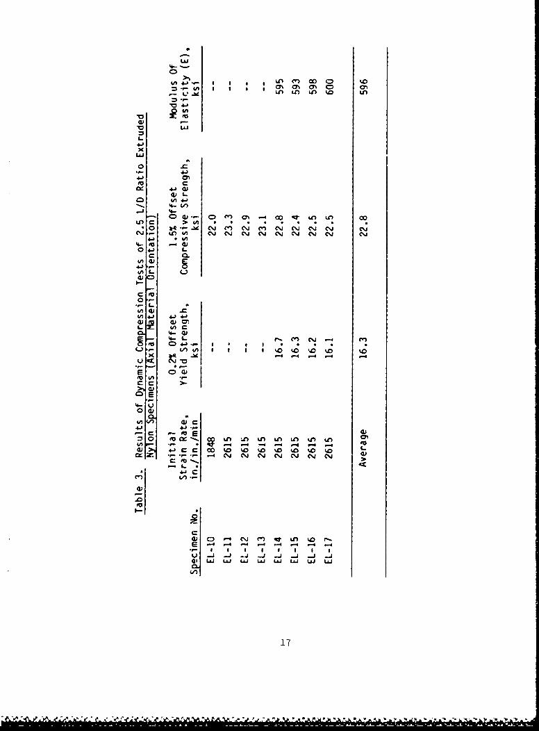
The results of the dynamic compression tests are presentedin Table 3 for both the noninstrumented specimens (EL-IO throughEL-13) and the strain-gage instrumented specimens (EL-14 throughEL-17). Due to the relatively poor signal response of the LVDTdisplacement measuring system utilized for specimens 10, 11, 12,and 13, no 0.2% yield strength or elastic modulus could bedetermined. The average values for the dynamic yield and com-pressive strengths and for the elastic modulus are listed at the
e WL
L&J
IfLA4-)- 00 CD %0 ~
LL
Li4J
4Ab
4-)x
'41
'4-E 414)
04- V)
4.-
0.-
V) 4 J 4J 4.)
4V '4- 0)CL 4 L r' '4).J
1,0) o I I I 1 %.0 %0 %D .0 'x _u -4 -SID
C;
0 4)
4-1 4.i.
a o)4
C -4 -4 -4 -4 -4-44
cr~ ~ ~ 21 .
-4 --4 4 -- e" -4 -4
17

bottom of Table 3. Static and dynamic stress/strain curvesrepresenting average values of modulus, 0.2% yield strength,and 1.5' offset compressive strength are shown in Figure 5.
23Nylon Zytel-1015/8 "Dia x 1.562" Length DynamicSpecimen 23.20(4)-Tests
20 a 43 ,n./in.isec. 22 570 2600 in.!n.,min. 21.86 1.5% Offse"
// 1.0% Offset Compressive
165 Yield Strength0.2% Offset
15 Yield 14.00 ksi
12.0 ksi 1.5% Offset Sac"Proportional Yie ld Elatic yeldtc
'a Limit (Approx.) Modulus10- E = 595.0 ks,0o (Dynamic)
zElastic Static CompressionModulus Nylon Zytel-l01
E = 550 ksi 3/8 "Dia x 0.75' Length
5.0 (Static) Specimen.0 0 kst 6 = 0.100 in.,'in.imin.ProportionalLimit
0 0.01 0.02 0.03 0 04 0 05 0.06 e In.,In.
0 1.0 20 3.0 4.0 5.0 6.0 % Strain
Strain
Figure 5. Static and Dynamic Stress/Strain Curves
The dynamic compression test results for the extruded Zytel101 specimens provide information on the material compressivebehavior at strain rates of the same orders of magnitude as aretypical of ballistic launch cor.ditions. Although the dynamiccompression test does not fully simulate the stress state of theobturator band, it does allow material strain rate effects to beevaluated and compared with slow-strain-rate test results undersimilar specimen stress states.
Comnparing dynamic compression test results for the fourinstrumented specimens with the results for the static compres-sion tests indicates that the primary effect of increasinastrain rate is to increase the materials yield and compressivestrength levels.
Using average values for the 0.2"ý yield and 1.51 compressivestrengths for comparison indicates that increasing the specimenstrain rate from 0.100 in./in./min to appi oximately 2600in./in./min results in a 47% and G3°) increase in yield and 1.5%compressive strength, respectively. In contrast to therelatively large increases in strength levels, comparison of
t p . '-• Z ,• - .-A , I Q . ?. ' . . . .- " L J

average modulus of elasticity for the two strain rates showsonly an 8% increase at the higher testing rates.
The unpublished results for static and dynamic tensiletests of Zytel 101 nylon performed at PNL indicate a muchstronger strain rate depondence for material properties in thetensile deformation mod(e. in this work, static tensile testingperformed at a strain rate of 0.04 in./in./min resulted in anelastic modulus value of 370,000 psi, while the dynamic tensiletest ( - 2,545 in./4n./min) indicated an E value of526,000 psi. Comparison of the static and dynamic 0.2% yieldstrength indicated that increasing strain rate resulted in anincrease in yield strength of approximately 58%.
These results are particularly interesting because theyindicate that for small, primarily elastic strains, the dominantcompressive deformation mechanism is relatively insensitive tostrain rate effects while comparable changes in strain rateresult in significant anelastic behavior for Zytel 101 in ten-sion. However, increases in strain rates appear to produceessentially equal increases in measured strength levels forZytel 101 in both the tensile and the compressive deformationmode.
4.3 HYDROSTATIC COMPRESSIVE PROPERTIES
As previously mentioned, a limited effort was made to eval-uate the compression properties of Zytel 101 under an elevatedconfining pressure. The two tests conducted on the 0.625-in.-diameter extruded compression specimens were performed by super-imposing an axial displacement on a specimen subjected to anelevated confining pressure of either 7,000 or 10,000 psi.Because of instrumentation problems, only the results of thefirst test, conducted at 7,000 psi confining pressure, arereported here. A plot of stress for this test as a function ofLVDT displacement is shown in Figure 6. Graphical estimates ofthe modulus of elasticity, E, and 0.2% offset yield strengthwere made and indicate a modulus of approximately 530,000 psi,13.0 ksi yield strength, and a 1.5% compressive strength of 15.5ksi. Material strain rat,, for the test was 0.032 in./in./min.
Although the results are in general agreement with the moreconventional compression test results reported previously,experimental difficulties with the LVDT displacement measuringsystem make specific comparisons difficult.
The significant result of this test is that subjecting thenylon specimen to an elevated confining pressure, which simu-lates hydrostatic loading conditions, apparently does not have amajor effect on the axial yield strength or modulus ofelasticity. This woujd indicate that, in contrast to conven-tional polymer theory, the yield behavior of extruded Zytel 101approaches that predicted by the Von Mises' criterion.
-----------------------------......................

Nylon Zytel-101 (Extruded)
5/8 "'Dia x 1.562" Length Specimen
15.5 kbi1.5% Offset
20 Elastic Modulus CompressiveE V 532 kui Strength
S15S~ 12.8 ksi
€ 0.2% Yieldzl Strength
S0 8.8 ksi
Z ProportionalLimit
O0 0.01 0.02 0.03 0.04 0.05 0.06 a in/in
1 0 2.0 3.0 4.0 5.0 6.0 a %
Strain
Figure 6. Hydrostatic Compressive Stress/Strain Curve
21

5.0 CONCLUSIONS AND RECOMMENDATIONS
1) The static and dynamic compression tests subject the nylontest material to a stress state that is more representativeof obturator band loading conditions than is possible withuniaxial tensile tests.
2) Comparison of compression test results for the two materialprocessing methods and orientation indicates that both theextruded and the centrifugally cast Zytel 101 materials canbe considered equivalent and isotropic in compressiveproperties.
3) The modulus of elasticity in compression for Zytel 101,determined by three different test methods, was found to berelatively insensitive tu strain rate effects. In contrast,increases in strain rate were founa to increase the yieldand 1.5% compressive strength by an average of 47% and 63%,respectively.
41 Limited experimental results obtained for deformation ofnylon at elevated confining pressures indicate that thehydrostatic stress component has a relatively small influ-ence on the elastic modulus and yield strength. Further
e,-ting with improved displacement instrumentation would berequired to confirm this observation.
5) To fully simulate the loading conditions associated withnylon obturator bands during ballistic launch conditionswould require development of a dynamic compression test inwhich an elevated confining pressure could be superimposed.
21
!WN = 1

REFERENCES
1. Modern Plastics Encyclopedia, 1981-82, Vol. 58, No. 1OA,McGraw-Hill, New York.
2. Krautrkrmcer, J., and Krautkramer, H., 1977, Ultrasonic Testringof Materials, 2nd Ed., Springer-Verlag, New York.
3. Alder, W.F., James, T.W., and Kukuchek, P.E., 1981, DeM entof a Dynamic Com pression Fixture for Brittle Materials,Technical Report CR-81-918, Effects Technology, Inc., SantaBarbara, California.
4. Dieter, G.E., 1976, echanical metallurgy, 2nd Ed., McGraw-Hill, New York.
22

APPENDIX
CALCULATION OF MATERIAL ELASTIC CONSTANTS FROM MEASUREDULTRASONIC WAVE VELOCITIES
S C1
Acoustic Velocity Ratio r = • (1)
Shear Modulus G PCs 2 (2)
Poisson's Ratio v = - r 2/2 (3)1 - r 2
Young's Modulus E = GL_ 4 r2] (4)
where C1 = longitudinal wave velocity
Cs - shear wave velocity
p = mass density of Zytel 101.
23
wa.

Table Al. Finite Element Obturator Stress Listing
Element Number Sx 8y Txy Sz(STIF 42) psi psi psi psi
402 -10899 -14474 -2793 -11150403 -2479 -5320 -3120 -3154405 1975 1528 -1388 1887406 -9257 -12774 -6704 -9671407 -5624 -9245 -279 -6298408 -3271 -12035 -3325 -6594
410 -5069 -6028 -1100 -4808411 -18552 -25528 -10732 -19945412 -20994 -28803 -2994 -21932413 -38302 -48929 -9084 -38543414 -35378 -41499 -2296 -34237416
477 -25624 -51123 -10655 -34127478 -45043 -66657 -10671 -49592479 -49427 -57920 -4898 -47495480 -44878 -54097 -5192 -43883481 -52514 -54562 -2080 -47608
494 -39046 -62902 422.3 -44920495 --56213 -76961 2886 --58995496 -58227 -92119 -7867 -66528497 -81202 -72622 7407 -68469498 -48991 -75580 -6543 -54933
499 -87191 -1.27 E6 -9023 -95468500 -56927 -65967 -2970 -54033501 -58299 -58932 -1579 -52072502 -65452 -84326 6732 -64983503 -55996 -67085 654.8 -52333
504 -58784 -62792 2046 -52599505 --57473 -61346 518 -51985506 60308 -60203 -816 -53444507 -65606 -66572 -352 -54912508 -63346 -64073 432 -54237509 61996 62080 1841 -53665
510 63618 --58330 1639 -53661511 -66354 -68811 -1464 -55903512 - 67308 -66630 431 -56210513 75900 -73375 217 -64010514 - 71863 -69816 2240 -61515515 -71004 -63640 2078 -59844

DISTRIBUTION LIST
No. of No. ofCopies Organization Copies Organization
12 Administrator I HQDA (DAMA-CSS-5), J. BryantDefense Technical Info Center Washington, DC 20310ATTN: DT]C-DDACameron Station I HQDAAlexandria, VA 22314 DAMA-ART-M
Washington, D.C. 20310Director of Defense
Research & Engineering (OSD) 10 Central Intelligence AgencyATTN: R. Thorkildsen Office of Central ReferenceWashington, DC 20301 Dissemination Branch
Room GE-47 HQSDirector of Defense Washington, DC 20502Research & Engineering (OSD)ATN: J. Persh 1 Commander
Washington, DC 20301 US Army Materiel Command
ATTN: AMCDRA-STDirector 5001 Eisenhower AvenueDefense Advanced Research Alexandria, VA 22333
Projects Agency1400 Wilson Boulevard I CommanderArlington, VA 22209 US Army Materiel Command
ATTN: DRCLDCDirector 5001 Eisenhower AvenueInstitute of Defense Analysiu Alexandria, VA 22333ATTN: Documents Acquisition1801 Beauregard Street CommanderAlexandria, VA 22311 US Army Materiel Command
ATTN: DRCDEHQDA (DAMA-MS) Deputy DirectorWashington, DC 20310 5001 Eisenhower Avenue
I HQA (AMAZA)Alexandria, VA 22333HQDA (DAMA-ZA)
Washington, DC 20310 1 CommanderUS Army Materiel Command
HQDA (DAMA-ZD), H. Woodall ATTN: DRCDE-RWashington, DC 20310 5001 Eisenhower Avenue
Alexandria, VA 22333HODA (DAMA-ARZ-A),
M.E. lasser 1 CommanderWashington, DC 20310 US Army Materiel Command
5001 Eisenhower Avenue2 HQDA (DAMA-CSN-VA) Alexandria, VA 22333
(DAMA-CSM-CA)Washington, DC 20310
25

DISTRIBUTION4 LIST
No. of No. ofCopies Organization -2) i:! Organization
8 Comm~ander 5 ComM.3nderUS Army AMCC0M US Army ANCCOM, ARDCATTN: SMCAR-LCA, A. Moss ATTN: SMCAR-LCU,
SM CAR- LC, E. BarrieresSMCAR- SE SMCAR-LCU, R. Davit(SMCAR- SA SMGAR-LCU-I',SMCAR-AC D. Robertson
F. ax U AmyMCRCUCUM-C.LasoTT:SMCAR-SCA-, CJ ce
AJ. Gero .Wis oldsei
SMCAR-LCF-,F.Sx SMCAR-SCA-, E. Leeser
SMCAR-LCUSS Doer NJA-SF L.78rmaNJ 0781 tiARSCZ P Ptrll
~~~~Dover, NJ 078017 Comne
~~~~SArmy AMCCOM, ARDC9 Comde
SICRTS US Army AMCCOM, ARDC MA-CSGodtiAT NJ 07801 ATTN SMCAR-SGM,
SMCASMCAR-SCM F.. Bloorek4 Co mandr-C SMCAR-SCM, E. Mulneri
USAmy AR-CCOAD SMCAR-SCS, B.. BSodmanzAT:SMCARTDC SMCAR-SCS, T. HurmngDoeNCAR-TDA SMrCAR-SCA, P. Gadomski
USAm MCAR-TDS 9 ComadeAT:SMCAR-TDC, C. Larmo SMCAR-SCA-T,
Doer NJ:z 0 7 8 0 1 ATTNr: SMCAR-SCA,.aMet
4 ~~~ ~ ~ ~ Commander SCRSM .Bo
US ~~~ ~ ~ ~ Army AMCCOM, ARDC SCRSM .Mlei
ATTN: Moor LIATTN SMCAR-LCA, B. WilliverSMCR-LS, . GegoitsSMCAR--LCA, T. Beungti
SMCAR-LCSD, .Ru SMCAR-LCA, W. GdemsitrcSMCAR-LCA, T.A-SA Daido Dove, NJ0780SMCAR-LCA, E. Fariedmn
SMCAR-LCAC.ALeSCergeDover, NJ 07801 P ezoe
7 Comandr SMAR-SA-TF. Dhd26
USAmIMCM RD oeN 70

DISTRIMBTION LIST
No. of No. ofCopies Organization Copies Organization
4 Commander CommandJrUS Army AmCCOH, ARDC US Army AMCCOM, ARDCATTN: SMCAR-LCA, S. Yim ATTN: Army Fuze Mgt
SHCAR-LCA, L. Rosendorf Project OfficeSMCAR-LCA, S.H. Chu SMCAR-FUSMCAR-LCW, R. Wrenn Dover, NJ 07801
Dover, NJ 07801
2 Commander6 Director US Army AMCCOM, ARDC
Bernet Weapons Laboratory ATTN: SMCAR-DPArmament R&D Center Development ProjectUS Army AMCCOM, ARDC Office tor SelectedATTN: SMCAR-LCB-TL Ammunitions
SMCAR-LCB Dover, NJ 07801SMCAR-LC B- RA,
R. Scanlon 2 CommanderSMCAR-LCB-RM, US Army AMCCOM, ARDC
M. Scarullo ATTN: ProductSMCAR- LCB- RA, Assurance Directorate
R. Soanes, Jr. SMCAR-QASMCAR-LCB-RA, Dover, NJ 07801
J. VasilakisWmt:ervliet, NY 12189 1 Commander
US Army AMCCOM, ARDC7 Director ATTN: SMCAR--NS
US Army AMCCOM, ARDC Dover, NJ 07801Benet Weapons LaboracoryATTN: SMCAR-LCB-RA, 1 Commander
T. Simkins US Army AMCCOM, ARDCSMCAR-LCB-D, J. Zweig ATTN: L. GoldsmithSMCAR-LCB-RA. G. Pfleg] Dover, NJ 07801SMCAR-LCB-M, J. PurtellSMCAR-LCB-RA, I Commande.e
R. Racicot US Army ARPCOMSMCAR-LCB-DS, ATTN: SMCAI-TSE-SW,
.J. Santini R. fladKiewicz
SMCAR-LCB-RA, I. Wu Rock Island, IL 61299Watervliet, NY 12189
2 Commander2 Commander US Army ARRCOH
US Army AMCCOM, ARDC ATTV: SMCAR-TEP-LATTN: SMCAR-SC' SMCAR-TSE-SY,
SMCAR-SC, B. Shulman G. StrahlDover, NJ o7801 Rock Island, I1. 61299
27

DISTRIBUTION LIST
No. of No. ofCopies Organization Copies Organization
Commander I Commander:JS Army ARRCOM ERADCOM Technical LibraryATTN: SARRI-RLS ATTN: DELSD-LRock Island, IL 61299 (Reports Section)
Fort Monmouth, NJ 07703-5301Commander
US Army Aviation Research Commanderand Development Command Atmospheric Sciences Lab.
ATTN: AMSAV-E USA Electronics Research4300 Goodfellow Blvd. and Development CommandSt. Louis, Mo 63120 ATTN: DELAS-EO-MO,
R.B. GomezDirector White Sands Missile RangeUS Army Air Mobility Research NM 88002
and Development LaboratoryATTN: Hans Mark 3 Commander
R.L. Cohen USA Harry Diamond Lab.Ames Research Center ATTN: DELHD-I-TR,Moffett Field, CA 94035 H.D. Oirchak
DELHD-I-TR, H. Davis2 Director DELHD-S-QE-ES,US Army Research & Technology 2800 Powder Mill Road
Laboratories Adelphi, MD 20783Ames Research CenterMoffett Field, CA 94035 Commander
USA Harry Diamond Labs.2 Director ATTN: DELHD-TA-L
US Army Research & Technology 2800 Powder MilJ RoadLaboratories Adelphi, MD 20783
ATTN: DAVDL-AS,DAVDL-AS, I Director
Ames Research Center Night Vision Laboratory
Moffett Field, CA 94035 Fort Belvoir, VA 22060
S2 CommanderUS Army Missile CommandResearch, Development and
Engineering CenterATTN: AMSMI-RD
AMSMI-YDI,Redstone Arsenal, AL
35898-5500
DirectorUS Army Missile and Space
Intelligence CenterATTN: AIAMS-YD)L
Redstone Arsenal, Al,
35898-5500

DISTRIRJTION LIST
No. of No. ofCopies Organization O(pies Organ za ion
2 CommandantUS Army Infantry SchoolATTN: ATSH-CD-CSO-OR 3 CommanderFort Henning, GA 31905 US Army Research OfficeP.O. Box 12211
2 Commander ATTN: Technical DirectorUS Army Missile Command Engineering DivisionATTN: DRCPM-TO Metallurgy & Materials
DRCP?4-HD DivisionRedstone Arsenal, AL 35898 Research Triangle Park,
NC 27709-2211
CommanderUS Army Mobility Equipment Director
Research & Development COd US Army Mechanics andFort Belvoir, VA 22060 Materials Research Center
ATTN: Director (3 cys)3 Commander DRXMR-ATL (I cy)
US Army Tank Automotive Ond Watertown, MA 02172ATTN: AMSTA-TSL
AMSTA-ZSA, R. Beck 2 CommanderAMSTA-NS US Army Materials and
Warren, MI 48397-5000 Mecharices Research CenterATTN: .3. Mescal]
I Commander Tech. Library
US Army Natick Research Watertown, MA 02172
and Development CommandATTN: DRDNA-DT CommanderNatick, MA C.762 US Army Training and
Doctrine CommandDirector ATTN: TRADOC Lib,US Army TRADOC Systems Fort Monroe, VA 23651
Analysis Activity CommanderATTN: ATAA-SLWhite Sands Missile Range, US Army Armor SchoolNM 88002 ATTN: Armor Agency, MG Brown
Fort Knox, KY 40121
2 PresidentUS Army Armor and Engineering 1 Commander
Board uS Army Field ArtilleryATTN: ATZK-AE-CV School
ATZK-AE-IN, L. Smith ATTN: Field Artillery AgencyFort Knox, KY 40121 Fort Sill, OK 73503
3 Commander Superintendent
US Army Research Office Naval Postgraduate SchoolATTN: R. Weigle ATTN: Dir of LibE. SEibel Monterey, CA 93940
J. Chandra
P.O. Box 12211 1 CommanderResearch Triangle Park USAFAC & Fort LeavenworthNC 27709-2211 Ft. Leavenworth,KS 66027-5080
29

DISTRIBUTION LIST
No. of 1No. ofcopies Organization Ooples Organization
Commander 3 CommanderUS Army Combat Development Naval Surface Weapons Center
Experimentation Command ATTN: Code E-31, R.C. ReedATTN: Tech Info Center M.T. WalchakBldg. 2925, Box 22 Code V-14,Fort Ord, CA 93941 W.M. Hinckley
Silver Spring, MD 20910Co~iander
Naval Sea Systems Commaiid 5 CommanderATTN: 9132 Naval Surface Weapons CenterWashington, DC 20362 ATTN: Code G-33,
T.N. TschirnCommander Code N-43, J.J. YaglaNaval Sea Systems Command L. Anderson
(SEA-62R41) G. Soo Hoo
ATTN: L. Pasiuk Code TX, W.G. Soper
Washington, DC 20362 Dahlgren, VA 22448
Commander 1 CommanuerNaval Research Laboratory Naval Weapons Center
ATTN: H. Peritt, China Lake, CA 93555Code R31
Washington, DC 20375 1 Commander
Naval Weapons CenterCommander ATTN: J. O'Malley
Naval Ship Research and China Lake, CA 93555Development Center
Bethesda, MD 20084 2 Commander
Naval Weapons Center5 Commander ATTN: Code 3835, R. Sewell
Naval Research Laboratory Code 3431, Tech Lib
ATTN: W.J. Ferguson China Lake, CA 93555C. Sanday
H. Pusey 2 CommanderTech Library US Naval Weapons Center
Washington, DC 20375 ATTN: Code 608, R. Derr
Code 4505, C. Thelen
6 Commander China Lake, CA 93555Naval Surface Weapons Center
ATTN: Code X211, Lib 3 CommanderE. Zimet, P13 Naval Weapono Center
R.R. Bernecker, R13 ATTN: Code 4057
J.W. Forbes, R13 Code 3835, B. LundstromS.J. Jacobs, RIO Code 3835, M. Backman
K. Kim, R13 China Lake, CA 93555
Silver Springs, MD 20910
1 CommanderNaval Ordnance Station
Indian Head, MD 20640
30

DISTRIDJTIO LIST
no. of No. ofCopies Organization Copies Organization
2 Commander 2 Battelle Memorial InstituteNaval Ordnance Station ATTN: L.E. HulbertATTN: Code 5034, Ch. Irish J.E. Backofen, Jr.
T.C. Smith 505 King AvenueIndian Head, MD 20640 Columbus, OH 43201
Office of Naval Research 3 Battelle Pacific NorthwestATTN: Code ONR 439, Laboratory
N. Perrone ATTN: M.T. SmithDepartment of the Navy F.A. Simonen800 North Quincy Street L.A. StropeArlington, VA 22217 P.O. Box 999
Richland, WA 99352CommandantUS Marine Corps Bell Telephone Labs. Inc.ATTN: AX Mountain AvenueWashington, DC 20380 Murray Hill, NJ 07971
1 AFATL/DLXP DirectorATTN: W. Dittrich Lawrence Livermore LaboratoryEglin AFB, FL 32542 P.O. Box 808
Livermore, CA 94550I AFATL/DLD
ATTN: D. Davis 2 DirectorEglin AFB, FL 32542 Lawrence Livermore Laboratory
ATTN: E. Farley, L92 ADTC/DLJW D. Burton, 1200
Eglin AFB, FL 32542 Livermore, CA 94550
I ADTC/DLODL, Tech Lib 3 DirectorEglin AFB, FL 32542 Lawrence Livermore Laboratory
ATTN: T.T. Chaio, L338
M.L. WilkinsR.M. Christensen, L338
Livermore, CA 94550I AYWL/SUL
ATTN: J.L. Bratton I DirectorKirtland AFB, NM 87117 NASA - Ames Research Center
Moffett Field, CA 940351 AFML/LLN (T. Nicholas)
Wright-Patterson AFB, 2 Forrestal Research Center
OH 45433 Aeronautical Engineering Lab.ArTN: S. Lam
2 ASD (XROT, G. Bennett; A. EringenENSSS, Martin Lentz) Princeton, NJ 08540
Wright-Patterson AFB,OH 45433 1 Sandia National Laboratories
ATTN: D.E. Waye
Livermore, CA 94550
31

DISTRIBUTION LIST
No. of No. ofCopies Organization Copies Organization
AFELM, The Rand Corporation I Kaman-TempoATTN: Library-D ATTN: E. Bryant1700 Main Street 715 Shamrock RoadSanta Monica, CA 90406 Bel Air, MD 21014
Aircraft Armaments Inc. 1 General Electric ArmamentATTN: John Hebert and Electrical SystemsYork Road & Industry Lane ATTN: D.A. GrahamCockeysville, MD 21030 Lakeside Avenue
Burlington, VT 054022 ARES, Inc.
ATTN: Duane Summers I Olin CorporationPhil Conners Badger Army Ammunition Plant
Port Clinton, OH 43452 ATTN: R.J. ThiedeBaraboo, WI 53913
2 AVCO CoroporationStructures and Mechanics Dept I S&D Dynamics, Inc.ATTN: W. Broding ATTN: M. Soifer
j. Gilmore 755 New York Avenue201 Lowell Street Huntington, NY 11743Wilmington, MA 01887
1 Soutnwest Research Institute3 BLM Applied Mechanics ATTN: P.A. Cox
Consultants 8500 Culebra RoadATTN: A. Boresi San Antonio, TX 78228
R. MillerH. Langhaar I Southwest Research Institute
3310 Willett Drive ATTN: T. JeterLaramie, WY 82070 8500 Culebra Road
San Antonio, TX 78228Martin Marietta LaboratoriesATTN: J.I. Bacile I University of DaytonOrlando, FL 32805 Research Institute
ATTN: S.J. BlessH.P. White Laboratory Dayton, OH 454693114 Scarboro RoadStreet, MD 21154 1 University of Delaware
Department of MechanicalCALSPAN Corporation EngineeringATTN: E. Fisher ATTN: H. KingsburyP.O. Box 400 Newark, DE 19711
Buffalo, NY 142256 University of Illinois
FMC Corporation College of Engineeringordnance Engineering Division ATTN: A. Zak (2)San Jogc, CA 95114 1). C. irucker
Urbana, IL 61801
32

DISTRIBUTION LIST
No. of No. ofOpies Organization Copies Organization
2 University of Iowa 4 SRI InternationalCollege of Engineering ATTN: D. CurranATTN: R. Benedict L. Seaman
E.J. Haug Y. GuptaIowa City, IA 52240 G.R. Abrahamson
333 Ravenswood AvenueRutgerc University Menlo Park, CA 94025
Dept. of Mechanical
and Aerospace Engineering 5 Brown UniversityP.O. Box 909 Division of EngineeringATTN: T.W. Lee ATTN: R. CliftonPiscataway, NJ 08854 H. Kolsky
A. PipkinUniversity of Wisconsin P. SymondsMechanical Engineering Depart J. MartinATTN: S.M. Wu Providence, RI 02912Madison, WI 53706
3 California Institute ofUniversity of Wisconsin TechnologyMathematics Research Center Division of Engineering610 Walnut Street and Applied ScienceATTN': B. Noble ATTN: J. MiklowitzMadison, WI 53706 E. Sternberg
J. KnowlesAFFDL/FB (J. Halpin) Pasadena, CA 91102Wright-Patterson AFB,OH 45433 1 University of California
at Los Angeles3 Honeywell, Inc. Department of Mechanics
Defense Systems Division ATTN: W. Goldsmith5901 South City Road 504 Hilgard AvenueEdina, MN 55436 Los Angeles, CA 90024
4 Los Alamos Scientific Lab. I Drexel Institute ofATTN; Tech Lib Technology
J. Taylor Wave Propagation ResearchR. Karpp CenterU.F. Kocks ATTN: P.C. Chou
P.O. Box 808 32nd and Chestnut StreetsLivermore, CA 94550 Philadelphia, PA 19104
4 Sandia National Laboratories I Harvard UniversityATTN: L. Davison Division of Engineering and
P. Chen Applied PhysicsL. Bertholf ATTN: G. CarrierW. Herrmann Cambridge, MA 02138
Albuquerque, NM 87115
33

DISTRIBUTION LIST
No. of No. ofCopies Organization Copies Orgauization
Iowa State University 2 Southwest Research InstituteDepartment of Engineering Department of Mechanical
Science and Mechanics SciencesATTN: C.P. Burger ATTN: U. Lindho]mAmes, IA 50010 W. Baker
8500 Culebra Road2 Iowa State University San Antonio, TX 78228
Engineering Research Lab.ATTN: G. Nariboli 2 University of Delaware
A. Sedov Department of MechanicalAmes, IA 50010 Engineering
ATTN: J. Vinson4 The Johns Hopkins University M. Taya
ATTN: J. Bell Newark, DE 19711R. GreenR. Pond, Sr. 3 t,-.versity of FloridaC. Truesdell norartment of Engineering
34th and Charles Streets cience and MechanicsBaltimore, MD 21218 ATTN: C. SciammarillA
L. MalvernLouisiana State University E. Walsh
Department of Mechanical Gainesville, FL 32611Engineering
ATTN: W. Sharpe 2 University of IllinoisP.O. Box 16006 at Chicago CircleBaton Rouge, LA 70803 College of Engineering
Dept. of Materials4 Massachusetts Institute Engineering
of Technology ATTN: A. SchultzATTN: R. Probstein T.C.T. Ting
A.S. Argon P.O. Box 4348F. McClintock Chicago, IL 60680K.J. Bathe
77 Massachusetts Avenue 2 University of MinnesotaCambridge, MA 02139 Department of Engineering
MechanicsNew Mexico Institute of ATTN: R. Fosdick
Mining and Technology J. EricksonTerra Group Minnedpolis, MN 55455Socorro, NH 87801
CommanderRensselaer Polytechnic Inst. Armament R&D CenterDepartment of Mechanical U.S. Army AMCCOM
Engineering ATTN: SMCAR-TSSATTN: E. Krempl Dover, NJ 07801Troy, NY 12181
34

DIMINTI(M LIST
go. of No. ofCOpies Organization Copies Organization
Commander I Yale UniversityArmament R&D Center Department of EngineeringU.S. Army AMCCOM and Applied ScienceATTN: SMCAR-TDC ATTN: A. PhillipsDover, NJ 07801 New Haven, CT 06520
Commander 2 Washington State UniversityU.S. Army Armament, Munitions Department of Physics
and Chemical Command ATTN: G.E. DuvallATTN: SMCAR-ESP-L R. FowlesRock Island, IL 61299 Pullman, WA 99163
Ccommander Aberdeen Provini GroundU.S. Army Aviation Research
and Develpment Command Dir, USAMSAAATTN: AMSAV-E ATTN:AMXSY-D4300 Goodfellow Blvd AMXSY-MP, H. CohenSt. Louis, MO 63120 AMXSY-G, E. Christman
Commander AMXSY-OSD, H. BurkeAMXSY-G, R.C. Conroy
U.S. Army Communications - AMXSY-LM, J.C.C. FineElectronics Co.nmand Dir, USAHEL
ATTN: ANSEL-ED ATTN:A.H. Eckles, IIIFort Monmouth, NJ 07703 Cdr, USATECOM
ATTN: AMSTE- CEAMSTE-TO-FDir, USCRDC, Bldg. E3516, EAATTN :SMCAR-RSP-ASMCAR-MUSMCAR- SPS- IL
Commander SMCAR-SC-LU.S. Army Development and SMCAR-MS
Employment Agency SMCAR-CLNATTN: MODE-TED-SAB SMCAR-CLN-D, L. ShaffFort Lewis, WA 98433 SMCAR-CLN-D,
F. DagostinAir Force Armament Laboratory SMCAR-CLN-D, C. HughesATTN: AFATL/DLODL SMCAR-CLN,Eglin AFB, FL 32542-5000 J. McKivrigan
SMCAR-CLJ-L6 Sandia National Laboratories
ATTN: C.W. RobinsonG.A. Benedetti
M.L. CallabresiD.J. BammannM.R. Birn),aumN.A. Lapetina
Livermore, CA 9455035
•'" '• • ', X' k • 'i•:..J •' :. .--.: .• -•,, ", • ,.' ,,,. ",, ,,'..",- - - -- "• ; ,,-.. .. ......... . . . . . ....- - -•-

USER EVALUATION SHEET/CHANGE OF ADDRESS
This Laboratory undertakes a continuing effort to improve the quality of thereports it publishes. Your comments/answers to the items/questions below willaid us in our efforts.
1. BRL Report Number Date of Report
2. Date Report Received
3. Does this report satisfy a need? (Comment on purpose, related project, orother area of interest for which the ieport will be used.)
4. How specifically, is the report being used? (Information source, designdata, procedure, source of ideas, etc.)
S. Has the information in this report led to any quantitative savings as faras man-hours or dollars saved, operating costs avoided or efficiencies achieved,etc? If so. please elaborate.
6. General Comr'ents. What do yov think should be changed to improve futurereports? (Indicate changes to organization, technical content, format, etc.)
Name
CURRENT Organization
ADDRESS Address
ý.ity, State, Zip
7, If indicating a Change of Address or Address Correction, please provide theNew or Correct Address in Block 6 above and the Old or Incorrect address below.
Name
OLOD OrganiYTat-onADDRESS
Address
City. State, Zip
(Remove this sheet along the perforation, fold as iidicated, staple or tapeclosed, and mail.)
- - .... . . .

I