evaluation of the liquefaction hazard - … a preliminary map of liquefaction risk was constructed;...
TRANSCRIPT
21
2. GEOTECHNICAL ZONATION OF THE CATANIA SOILS ANDEVALUATION OF THE LIQUEFACTION HAZARD
2.1 Introduction(M. Maugeri and E. Faccioli)
It is well known that local geological and topographic conditions play a majorrole on earthquake ground motions and distribution of damage. This aspect becomeseven more critical in areas with sharp transitions between stiff surface formationsand softer soil materials, typically found in a volcanic zone like Catania which lies atthe foot of the Mt. Etna volcano and was affected by many eruptions in historical andpre-historic times. Hence, a substantial effort was devoted to the zonation andseismic characterisation of soils in the Catania area. This task was carried out both byexploiting the existing data and by performing special investigations at some selectedsites.
The creation of a database of about 860 boreholes provided the basis for ageotechnical zonation of the Catania municipal area; based on existing in situ tests(SPT, CPT, cross-hole and down-hole measurements) the mapping of the shear wavevelocity for earthquake engineering purposes was carried out. All the borehole and insitu test data were stored in the database and the investigation sites located via GISsystem (see 2.2).
To integrate the previous data, investigations were carried out for measuringthe shear wave velocity by surface wave methods (see 2.3), in particular SASWinvestigations have been performed at beach sites south of the city (La Plaja), wheresaturated sand deposits exhibit a marked susceptibility to liquefaction.
Laboratory cyclic tests were performed to characterise the non linear soilbehaviour, which may occur during strong earthquakes, such as the 1693 scenarioearthquake (see 1). Two boreholes were made, in which down-hole velocitymeasurements have been executed, and undisturbed samples were retrieved.Resonant column tests and cyclic loading torsional shear tests were performed toinvestigate the initial shear modulus Go and shear modulus degradation with shearstrain, as well as damping ratio degradation (2.4).
Land vulnerability to earthquake-triggered phenomena was also investigated,mainly from the viewpoint of landslide and liquefaction hazard. For the landslideproblem, one significant case was considered (Monte Po slide), but the data availableare insufficient and it will not be treated in the following. On the other hand, soilliquefaction effects were reported by historical sources following the 1693 and 1818earthquakes (see 2.5).
The susceptibility of a site to seismic-induced liquefaction may be assessedcomparing the cyclic soil resistance to the cyclic shear stresses induced by theground motion. The latter is of course a function of the earthquake parameters, whilethe former depends on the soil shear strength and can be computed using results fromin situ tests.

22
A preliminary map of liquefaction risk was constructed; eleven potentiallyliquefiable sites have been identified, where the liquefaction potential has beenevaluated based on SPT and CPT data, and also on Vs data. In particular, all thesedifferent data were available at one specific site (San Giuseppe La Rena), where thethree previous methods were employed and the results compared for a betterassessment of liquefaction potential (2.6).

23
2.2 Geotechnical zoning of the urban area of Catania for earthquakeengineering porposes(V. Pastore and R. Turello)
2.2.1 Introduction
Since the beginning of the Catania Project, in 1996, it has been recognised thatthe construction of realistic earthquake damage scenarios for the city of Cataniawould require a reasonably detailed model of the surface geology and geotechnicalcharacteristics of the area.
To achieve this goal, data from geotechnical borings, water wells, geophysicalinvestigations and geotechnical laboratory test have been collected, reprocessed andorganised in a digital database. Subsequently, using the processed data, a number ofgeotechnical cross-sections, representative of ground conditions of different zones inthe Catania urban area were prepared.
Based on the cross-sections and on an existing local geological map, a map ofgeotechnical units has been created; this was verified in the field and integrated withnew data for the specific purpose of the Catania Project.
Each geotechnical unit in the map has been described through the values ofselected parameters measured in the borings and on the recovered soil samples, orthrough geophysical investigations. The choice of the parameters has been stronglyoriented towards the seismic characterisation of the different soil materials. As a by-product of the basic geotechnical map, a map of the distribution of near surface S-wave velocity (VS) values in the area of interest was prepared.
Based on the data provided by some 860 borehole investigations, a depthcontour map of the top of the clays constituting the base formation of the referencesequence has also been drawn, as well as a map of the water table.
The results of this study are available by anonymous-ftp at:esdra.stru.polimi.it.
2.2.2Geological framework
Three fundamental structural domains can be recognised in Eastern Sicily (Fig.2.1): the Hyblean Foreland, a Triassic to Quaternary thick calcareous sequence withfrequent tectonically undisturbed volcanic episodes; the Gela-Catania Foredeep,filled up with Pliocene-Quaternary deposits; the Appenninic-Maghrebian Chain(Lentini, 1982).
Only the most recent deposits of the Foredeep dominion outcrop in the area ofCatania, , representing a time interval that spreads from Miocene to Quaternary,locally covered by recent and present deposits, both marine and continental.
North of Catania, the effusive materials from the Etna volcano predominate.Slightly to the South of the urban area, in the zone called the “Terreforti” hills, asedimentary series of Pleistocene age outcrops (South-Etnean series). At the base ofthe series there are grey-bluish marly clays (Kieffer, 1971) interbedded with

24
quartziferous sandy silts (Francaviglia, 1940). The observed thickness rangesbetween 10 and 100 m; the maximum thickness can however be considered ofhundreds of meters, as found in the deep borings in the Catania plain.
CataniaSICILY
T3
T3
Alg
Alf
R-Dt
Cc
P
E
X
ASg
M Aa
Ai
SG
37°34'17"
14°55'17"
37°34'12"
15°07'12"
37°20'41" 37°20'41"15°07'29"14°55'18"
Palermo
0 5 km
Fig.1
T4
T5T4
T2T2
T5
Figure 2.1 - Map of geotechnical units of the municipal area of Catania (see Table 1 for definition).
Overlying the grey-bluish marly clays there is a sequence, about 50 m thick, ofgreenish and yellow clays interbedded with layers of fine sands, with rare sandstonehorizons with calcareous cement; horizons of pyroclastic material are also present.

25
Coarser deposits follow upward, consisting of sands, gravels and pebbles locallyshowing some stiffness due to cementation (sandstones and conglomerates), withmaximum thickness of the order of 40 m.
Interbedded tuffs occur in every stratigraphic term of Pleistocenic age (tuff arealready reported in the upper portions of the grey-bluish clays), but mostly at the topand inside of the sand and -gravel layers.
South of the Terreforti Hills lies the Catania flood plain, a lowlandcharacterised by recent and present alluvium deposits grading to coastal deposits(Giovannino et al., 1960). The depth of these deposits is between 40 and 80 m.
The flood plain is limited to the South by hilly relief, where ancient terrains arepresent, ranging from Miocene to infra-Pleistocene age (North-Hyblean series), madeup by limestones, marls and calcarenites with clayey layers. All these rocks arecrossed at different levels by alkaline lava flows.
2.2.3Data collection and elaboration
The data largely consist of the stratigraphic log of borings (geotechnicalboreholes, water wells, etc.), characterised by variable degrees of accuracy; some areaccompanied by in situ and/or laboratory tests. In total, the database assembled forthe project includes 860 boring locations, with a density distribution of theinvestigation points highly varying from site to site. Processing of this informationhas resulted in the mentioned map of geotechnical units, shown in Fig. 2.1, linked toa digital boring database via the GIS Arc-Info.
Because of their relevance on the estimation of local ground shaking and siteeffects, data from in-hole geophysical surveys (down- and cross-hole measurements)and Seismic Analysis of Surface Waves (SASW technique) have been examined withspecial attention, particularly for S wave velocity measurements. Down-hole datawere available from previous investigations at six different sites, in the urban areaand in the industrial zone (located South of the urban agglomeration) of the plain.They include measurements in different lava flows, tuffs, sandy and marly clays andalluvial fine-grained deposits.
For the specific purpose of the Catania Project, two new borings were executedin 1997 to the depth of 40 m in the central city area (via Stellata and Piazza Palestro),with down-hole tests and sample recovery (see sub-sect. 2.4 below for the test resultsobtained from the samples). Specifically performed for the Project in 1997 were alsothree investigations using surface wave techniques for determining the Vs profiles,described in sub-sect. 2.3 below. Such investigations concerned the playa sand ofcoastal deposits, some conglomerates, and a lava flow.
2.2.4Adopted procedure
First, the boring data have been summarised according to a simple lithologicaldescription, through the choice of few fundamental classes. Next, a number of cross-sections have been drawn through the area of study (see Fig. 2.1), describing the

26
borehole logs according to the fundamental classes. Based on these cross-sections,and making reference to the geological model of the area, the geotechnical unitsgiven in Table 2.1 have been defined and characterised.
The denominations of the fundamental classes are consistent with thedefinitions of the Italian Geotechnical Association (AGI, 1977), considering grainsize fractions and their percentage relationship: peats, clays, silts, sands, gravels andpebbles are defined with the first letter of the name (in Italian T, A, L, S, G, C),while their percentages are expressed with simple notations (conjunction, comma orparenthesis).
Table 2.1: geotechnical units.R - Dt Top soil and fill (R); debris and landslides (Dt)
M Marine deposits
Alf Fine alluvial deposits (silts and clays with subordinated sand lenses)
Alg Coarse alluvial deposits (sands, gravels and pebbles)
X Scoriaceous lavas, lavas in blocks, "rifusa" and volcanoclastic rocks
E Fractured to slightly fractured lavas, with subordinated horizons of scoriaceouslavas, lavas in blocks, "rifusa" and volcanoclastic rocks
P Pyroclastic rocks
SG Yellow or brown quartzose sands and sandstone, gravels and conglomerates withpyroclastic alternations
ASg Yellowish or brown clays ans sandy silts, with sandy interbeddings andpyroclastic alternations
Aa Silty clays and grey-bluish marly clays
Ai Clayey interlayers in Cc unit
Cc Calcarenites and block-calcarenites; limestone, marly limestones and alternationsof marls and limestones
2.2.5Geotechnical characterisation
In a second, detailed phase of the geotechnical characterisation of the variousunits identified, we evaluated characteristic (average) values of some representativegeotechnical parameters, as shown in Table 2.2.
The following soil parameters were considered:• Physical characteristics (unit weight, moisture content, grain size, Atterberg’s
limits)• Shear strength (in drained and undrained conditions)• Shear wave propagation velocity Vs.

27
It must be noted that the previous parameters were selected on the basis of bothdirect measurements and empirical correlations with in situ or laboratory tests: atypical example is the angle of effective shearing resistance φ′ and the relativedensity Dr of the granular materials M-A1g-P-SG, which have been estimated fromwell known correlations with the measured NSPT values).
For the Cc and Ai formations outcropping in the South–western portion of theCatania municipal area, very few geotechnical data was available, given the smallnumber of borings made in this zone. Therefore, geotechnical parameters wereestablished from existing geological literature and from the correspondingdescription and estimated age of the materials.
The artificial fill materials (R) at the surface and the debris deposits (Dt), areextremely heterogeneous. It has been assumed that a unique characterisation of suchmaterials was not feasible, due to the extreme local variability of composition anddegree of compaction.
2.2.6Thematic maps
2.2.6.1Geotechnical units
The map of geotechnical units (Fig. 2.1) including the cross-sections, togetherwith the borehole digital database accessible via GIS, represent the main operatingtool contributed by this study for the creation of a seismic loss scenario in the townarea of Catania. As shown in the following sections of this report, this tool has beenused in the creation of scenario ground shaking maps via an engineering approach, aswell as in more sophisticated modelling approaches to obtain acceleration synthetics.
The reliability of the geotechnical map varies from place to place, according tonumber and quality of available boring data. In the urban area, boreholes and densityof data are rather high, and the map is believed to represent ina realistic way thegeotechnical nature of the foundation soils.
For instance, the thickness of lava flows has been determined with goodaccuracy, as well as the depth of grey-bluish marly clays top. In the Catania plain thetrend of the clay base formation and thickness of alluvial deposits have been quitewell ascertained with data of some deep water-wells.
2.2.6.2Shear wave velocity
Contours representing the estimated average values of Vs in the uppermost 30m, or Vs(30), were drawn, starting from the available data from in situ cross-hole,down-hole and surface wave tests. Areas with overall lava flow thickness exceeding10 m (within the uppermost 30 m) have been excluded from the contour linedatabase, since their extremely high values could substantially bias the numericalinterpolation, leading to misleading interpretation. The final shear-wave velocity mapis shown in Fig. 2.2.

28
Figure 2.2 - Map of average shear wave velocity (m/s) in 0÷30 m depth interval. The studied areacorrespond to the municipal area of Catania (see key map). Co-ordinates are written in latitude andlongitude format. (1) Sectors with lava thicker than 10 m in 0÷30 m interval (shaded); external limitof sectors with lava thinner than 10 m in 0÷30 m interval (bold lines). (2) Seismic survey sites (down-hole, cross-hole, SASW).
ReferencesA.G.I. (1977). Moduli and Damping factors for dynamic analyses of cohesionless soils.
Earthwake Eng. Res. Center. Report UCB/EERC-84/14.Bolton Seed H., Wong R. T., Idriss I. M., Tokimatsu K. (1984). Moduli and Damping factors
for dynamic analyses of cohesionless soils. Earthwake Eng. Res. Center. ReportUCB/EERC-84/14.

29
Bousquet J.C., Gresta S., Lanzafame G., Paquin C. (1987). Il campo degli sforzi attuali equaternari nella regione dell’Etna. Mem. Soc. Geol. It., 38, 483-506.
Carrubba P., Maugeri M. (1988). Determinazione delle proprietà dinamiche di un’argillamediante prove di colonna risonante. Rivista Italiana di Geotecnica, 22, 2, 101-113.
Cascone E., Cavallaro A.M.F., Maugeri M. (1996). Analysis of impact and traffic-inducedvibrations for the characterization of a clayey soil, 11th World Conference on EarthquakeEngineering, Acapulco, Mexico, 23-28 June, 1848.
C.N.R., Istituto Internaz. di Vulcanologia (Catania) (1979). Carta geologica del Monte Etna.Giovannini E., Accordi B., Lugo P. (1960). I terreni della Piana di Catania. La geologia del
bacino del Simeto, Tecnica Agricola, XII, 3, 219-244.Francaviglia A. (1940). Osservazioni geologiche sulle colline delle terreforti (regione etnea).
Giornale di Geologia, XIV , 55-81, Bologna.Frenna S.M., Maugeri M. (1995). Analisi della risposta del terreno nella Piana di Catania
durante il terremoto del 13/12/1990, VII National Conference of Associazione Nazionaledi Ingegneria Sismica - L’Ingegneria Sismica in Italia -Siena , 25-28 September 1995, 1,205-214.
Kieffer G. (1971). Dépôts et niveaux marins et fluviatiles de la région de Catane (Sicile),leurs corrèlations avec certains èpisodes d’activitè tectonique ou volcanique. Abstract of“Mediterranée”, 5-6, 591-626.
Lentini F. (1982). The geology of the mt. Etna basement, Mem. Soc. Geol. It., 23, 7-25.Lombardo G. (1985). Approach to the seismic microzoning of the area of Librino (Catania
Italy), Bollettino di Geofisica Teorica ed Applicata, XXVII , 25-40.Maugeri M. (1983). Indagini geotecniche per la valutazione della proprietà dinamiche di un
terreno argilloso, Procedings of XV National Conference of Geotechnics, Spoleto 4-6May 1983, III , 147-152.
Maugeri M., Frenna S.M. (1988). Determinazione del modulo trasversale del terrenomediante prove con vibrodina, Procedings of C.N.R. Conference Soil deformation andsoil-structure interaction under operational conditions, Monselice (PD), 5-6 October1988, 1246-1263.
Maugeri M., Frenna S.M., Spatola P. (1996). On Rayleigh waves propagation in layeredsoils, World Conference on Earthquake Engineering, Acapulco, 23-28 June, 1840.
Maugeri M., Carrubba A., Carrubba P. (1988). Caratterizzazione dinamica e risposta delterreno nella zona industriale di Catania, Ingegneria Sismica, 2, 9-18.
Ohta Y., Goto N. (1978). Empirical Shear Wave Velocity Equations in Terms ofCharacteristics Soil Indexes, Earthquake Engineering and Structural Dynamics, 6.
Puglia A., Addia R., Relazione di dettaglio delle aree a sud della circonvallazione di Catania,Geological-geotechnical study for the master plane of the town of Catania.
Puglia A., Addia R., Catania N., Ciappina A., Relazione geologico-tecnica. Geological-geotechnical study for the master plane of the town of Catania.
Romano R., Sturiale C. (1981). Geologia del versante sud-orientale etneo: F 270 IV (No, Ne,So, Se). Boll.Soc.Geol. It., 100, 15-40.
Schmertmann J.H. (1975). Measurement of in situ Shear Strength, Proceedings ASCESpecialty Conference on In-Situ Measurement of Soil Properties, 2, 57-138, Raleigh.
Sciuto Patti C., 1877, Carta idrografica della città di Catania e dintorni.Sturiale C. (1967). Su alcune piroclastiti del basso versante meridionale dell’Etna. Abstract
from Rendiconti della Soc. Mineralogica Italiana, XXIII , 427-452.Wezel F.C. (1966). I terreni quaternari del substrato dell’Etna. Atti della Accademia Gioenia
di scienze naturali in Catania, suppl. sc. geologiche, 271-281, Catania.

Uni
tV
alue
s of
soi
l par
amet
ers
Uni
tV
alue
s of
soi
l par
amet
ers
Cc
γ =
21.0
÷ 2
3.5
kN/m
3E
E1
- po
orly
frac
ture
d to
med
ium
frac
ture
d la
vav S
= 50
0 ÷
800
m/s
γ =
22.0
KN
/m3
Ai
γ =
21.0
÷ 2
3.5
KN
/m3
v S =
750
÷ 1
500
m/s
c U =
150
÷ 2
50 [k
Pa]
for
dep
th<
10 m
from
g.l.
E2
- ve
ry fr
actu
red
lava
c U =
250
÷ 4
00 [k
Pa]
for
dep
th >
10 m
from
g.l.
γ =
24.
0 K
N/m
3
v S =
300
÷ 4
50 m
/s f
or d
epth
< 10
m fr
om g
.l.v S
= 3
50 ÷
500
m/s
v S =
450
÷ 6
50 m
/s f
or d
epth
>10
m fr
om g
.l.v P
= 1
700
÷ 30
00 m
/sA
aγ
= 19
.5 ÷
20.
2 K
N/m
3 (
incr
easi
ng w
ith d
epth
)X
γ =
18.0
÷ 1
8.5
KN
/m3
w =
24
÷ 29
% (
gene
rally
dec
reas
ing
with
dep
th -
26%
on
aver
age)
v S =
180
÷ 3
00 m
/sLL
≥ 5
5 %
(ty
pica
l val
ues
60%
)v P
= 7
00 ÷
800
m/s
IP =
30
÷ 38
%P
γ =
16.0
÷ 1
7.0
KN
/m3
Gs
= 2.
70 ÷
2.7
4φ‘
= 3
3 ÷
38°
(es
timat
ed v
alue
s fr
om S
PT
cor
rela
tions
)c U
= 8
0 ÷
90 k
Pa
at s
hallo
w d
epth
s (w
eath
ered
mat
eria
l)C
’ = 0
÷ 2
0 kP
a (
assu
me
zero
for
unce
men
ted
mat
eria
l of t
he p
lain
)c U
= 20
0 ÷
250
kPa
for
dep
th >
10 m
from
g.l.
(up
to 4
00 k
Pa)
v S =
250
÷ 5
00 m
/sv S
= 3
20 ÷
450
m/s
for
dep
th<
10 m
from
g.l.
v P =
110
0 ÷
1500
m/s
v S =
450
÷ 6
00 m
/s f
or d
epth
≥ 1
0 m
from
g.l.
Alf
γ =
18.5
÷ 1
9.5
KN
/m3
v P =
165
0 ÷
1700
m/s
w =
27
÷ 32
%A
Sg
San
dy fa
cies
(co
hesi
onle
ss)
LL ≥
44
÷ 53
%γ
= 19
.3 ÷
20.
0 K
N/m
3IP
= 1
9 ÷
27%
φ‘ =
33
÷ 39
° (
estim
ated
val
ues
from
SP
T c
orre
latio
ns)
c U =
30
÷ 50
kP
a f
or d
epth
<10
mC
’ = 0
c U =
50
÷ 80
kP
a f
or d
epth
≥ 1
0 m
v S =
220
÷ 4
00 m
/s f
rom
dow
n-ho
le te
sts
φ‘ =
25
÷ 28
°v P
= 1
350
÷ 14
00 m
/s
fro
m d
own-
hole
test
sC
’ = 0
÷ 1
5 kP
aC
ohes
ive
faci
esv S
= 1
30 ÷
210
m/s
fro
m d
own-
hole
test
sγ
= 19
.3 ÷
20.
0 K
N/m
3 (
incr
easi
ng w
ith d
epth
)v P
= 3
50 ÷
450
m/s
fro
m d
own-
hole
test
sw
= 2
3 ÷
32 %
Alg
γ =
18.0
÷ 1
9.5
KN
/m3
LL ≥
55
÷ 60
%D
r =
50 ÷
65%
IP =
28
÷ 36
%φ‘
= 3
3 ÷
38°
c U =
70
÷ 15
0 kP
a (
from
labo
rato
ry T
X-U
U a
nd U
C)
C’ =
0φ‘
= 2
4 ÷
25°
(fr
om d
irect
she
ar te
sts,
n 4
ser
ies)
v S =
210
÷ 2
80 m
/sC
’ = 1
0 ÷
20 k
Pa
v P =
400
÷ 5
00 m
/sv S
= 2
20 ÷
400
m/s
fro
m d
own-
hole
test
sM
γ =
18.3
÷ 1
9.7
KN
/m3
v P =
135
0 ÷
1400
m/s
fro
m d
own-
hole
test
sD
r =
60 ÷
70%
SG
γ =
19.8
÷ 2
0.8
KN
/m3
φ‘ =
34
÷ 38
° (
estim
ated
val
ues
from
SP
T c
orre
latio
ns)
Dr
= 70
÷ 8
5%C
’ = 0
φ‘ =
36
÷ 40
° (
estim
ated
val
ues
from
SP
T c
orre
latio
ns)
v S =
210
÷ 2
80 m
/sC
’ = 0
÷ 7
0 kP
a (
assu
me
zero
for
unce
men
ted
mat
eria
l of t
he p
lain
)v P
= 5
00 ÷
550
m/s
v S =
350
÷ 5
00 m
/sR
,Dt
γ =
17.0
÷ 1
9.0
KN
/m3
v P =
130
0 ÷
1600
m/s
v S =
130
÷ 2
20 m
/s; v
P =
350
÷ 4
00 m
/s
Tab. 2.2: Characteristic values of some representative geotechnical parameteers

31
2.3 Seismic characterisation of the representative soils of Catania(C. Nunziata, G. Costa, M. Natale, A. Sica, R. Spagnuolo)
2.3.1 Introduction
We illustrate in this contribution the work performed on two topics relevant tothe characterisation of the soil behaviour in the Catania area under strong earthquakeshaking, such as expected for the scenario events.
Firstly, to enlarge the limited database of in-hole geophysical surveys of theshear wave velocity Vs (described in 2.2), independent seismic measurements of thisquantity have been carried out by surface wave techniques along a few profiles.These include some of the most representative near-surface geological materialsfound in Catania (Fig.2.3), such as the shore sands, the conglomerates of the“Terreforti” Formation (see also sub-sect. 2.2), the lava flow of the 1669 Etnaeruption (Recent Mongibello), and the Larmisi lava flow of the Prehistoric Etnaeruption (Prehistoric Mongibello).
Secondly, the liquefaction potential of the shore sands at La Plaja beach hasbeen evaluated by means of the standard approach based on the estimation of a safetyfactor between the cyclic shear resistance to liquefaction and the earthquake inducedshear stresses. In addition, an empirical correlation between shear seismic velocitiesVs and horizontal peak ground accelerations (Andrus and Stokoe, 1996) has beenused.
Figure 2.3 - Geological sketch map of the Catania area.
a
bc
N
La Plaja beach S. Giorgio Alto
Nesima Superiore ex San Berillo quarter6
Catania
Industrial area
0 1 km
Legend:1. Etna volcanic products2. Fluvial deposits of sand and conglomerates3. Present & recent alluvial deposits4. (a) Marshy deposits, (b) Shore dunes, (c) Present beach deposits5. Catania accelerograph station6. Location of the investigated sites.
1
2
3
4
5

32
2.3.2 Determination of Vs profiles
The Vs velocity profiles have been evaluated through the inversion of Rayleighgroup velocities. The FTAN method (Dziewonski et al., 1969; Levshin et al., 1972)has been employed to measure group velocities, since it can be used even whenhigher mode contamination occurs. A sequence of frequency filters and timewindows has been applied to the dispersion curve for an easy extraction of thefundamental mode. The dispersion curves obtained in such way have been invertedwith the non-linear Hedgehog method developed by Valyus et al. (1968) anddiscussed in detail by Panza (1981). By this approach, a number of solutions(profiles) are obtained that are within an assigned error band, depending upon thequality of the measurements.
In the following we present the Vs profiles, Hedgehog solutions for eachsurveyed site.
Shore sand at the La Plaja beachAlong the southern coast line of Catania, at the La Plaja beach, seismic
measurements with forward and backward spreadings of 32 and 64 m have beencarried out (Fig. 2.3).
The investigated site is characterised by fine sands with thin interbeddings ofgravelly sands having a mean grain size between 0.24 mm (in the uppermost 10 m ofsoil) and 0. 13 mm. The water table lies around 2 m below the ground surface. Conepenetration tests (CPTs) show a sharp decrease of the tip resistance values qc1,corrected of the overburden pressure and fine content (Robertson, 1990), whichcorrespond to a change of relative density Dr from 75% to about 40%. This trendseems to be correlated with Vs profiles showing an increase of velocities at 2-3 m ofdepth, then a decrease of them at 5 m of depth, and again an increase at 11 m ofdepth (Fig. 2.4). All the profiles exhibit Vs values of 220 m/s at 5-11 m of depth and280 m/s up to 20m of depth (Nunziata et al., 1999).
An estimation of the seimic quality factor Q was also obtained from thecomparison of the synthetic fundamental mode computed for one of the Hedgehogsolutions with that extracted from the measured signal. A gross Q value of 70 wasobtained (Nunziata et al., 1999).
Conglomerates at S. Giorgio AltoSeismic measurements have been executed in a quarry of fluvial deposits of
conglomerates and sands (Terreforti formation) at S. Giorgio alto (Fig. 2.3). Thesignals recorded at 100, 110 and 130 m offsets in a refraction survey have beenanalysed. The Hedgehog solutions obtained from the inversion of the average FTANgroup velocity give a detailed Vs profile down to 30 m depth (Fig. 2.5). The averageVs values increase from 320 m/s at 3 m of depth, up to 450 m/s at 30 m of depth. Thehigh velocity in the topmost 3 m of conglomerates may be an effect of the soilcompaction due to the truck traffic inside the quarry (Nunziata et al., 1999).

33
Figure 2.4 - Geotechnical and shear seismic properties of shore sands of Catania at La Plaja beach;qc1 corrected of overburden pressure and fine content; the blow count number N1, corrected ofpressure, and computed from the qc1 by the empirical correlation given by Tatsuoka et al. (1990) andMeyerhof (1957). The Vs models (Hedgehog solutions) and the average model (thick line) are shown(Nunziata et al., 1999).
1669 Lava flow at Nesima SuperioreSeismic measurements with forward spreadings of 27 and 37 m have been
carried out in the western part of the urban area (Fig. 2.3), close to the CivilProtection building, located in viale Lorenzo Bolano. Lava flows from Mt. Etnaerupted in 1669 outcrop at the investigated site. They consist of scoriaceous andvacuous lava, highly fractured at higher depths. The Hedgehog solutions obtainedfrom the inversion of the average FTAN group velocity have provided a Vs profiledown to 15 m depth. The Vs velocities are consistent with the volcanological data,since they have average values of 110 m/s for the topmost 4.5 m and of 150 m/sdown to 15 m of depth (Fig. 2.6).
2.3.3 Liquefaction potential of the shore sands at La Plaja beach
To evaluate the liquefaction potential of the shore sands at La Plaja beach, thestandard safety factor method has been used first; see e. g. Ishihara (1993) for adetailed description. The method requires that a safety factor F be computed, definedas the ratio between the cyclic resistance ratio (CRR) and the cyclic stress ratio(CSR) induced by the reference earthquake. At each depth, liquefaction is said to belikely if F is less or equal to 1. The liquefaction potential has been evaluated both forthe earthquake of December 1990 (so-called “St.Lucia earthquake”), for which a fewstrong motion records are avialable, and for the level I scenario earthquake, i. e. anassumed repetition of the M≅7, 1693 event. The S. Lucia earthquake (ML=5.4) waspresumably generated by a rupture along the transverse segment of the Maltaescarpment fault, and was recorded in Catania at an accelerograph station lying on
0
4
8
1 2
1 6
2 0
F ine c onten t (% ) qc (kg /m q ) N D r (% ) V s (m /s )1 1
0 40 80 0 100 200 0 30 60 50 100
Dep
th (
m)
F ine sandSa nd w ithgravel ly in tercala tion
0 200 400

34
some 60 m of alluvium (see also 4.1 below). Using SHAKE, the recordedaccelerogram has been reduced by deconvolution to the seismic bedrock (assumedVs=800 m/s) represented by the blue clay formation (Aa, see sub-sect. 2.2 Table 2.2).
We have also estimated the peak acceleration of the scenario earthquake (M7.0 to 7.5) using an attenuation law.
Moreover, we have considered the accelerogram recorded at Sortino station, onrock, at the same epicentral distance but at different azimuth.
The scenario earthquake has been simulated starting from the normal fault ofthe Malta escarpment. Two synthetic seismograms have been taken into account,both computed for 2D models of the local earth crust. The first one, computed byRomanelli and Vaccari (1999, see also 4.2 below), is relative to a 1D referencemodel (amax = 0.45g) and has been associated to outcropping seismic bedrock. Thesame waveform has also been scaled to amax = 0.35g. The second syntheticaccelerogram, computed by Priolo (1999, see also 4.1 below), is relative to areceiver on the top of 75 m soil column. This waveform has been treated in twodifferent ways: 1) by associating it to the ground surface, and computing the cyclicstress ratio (CSR) values down to 20 m depth along the soil column assumed by theauthor; 2) by reducing it by deconvolution to 75 m of depth, to suppress theamplification effect of the soil column, and later assuming it as input to our soilvelocity profile (Fig. 2.4).
All the previous waveforms are represented in Figure 2.7 in terms ofacceleration response spectra. The 1D amplification effect of the shore sands hasbeen computed taking into account the variation of shear modulus and damping withshear strain according to Seed and Idriss (1982).
The safety factor F against liquefaction is found to be greater than 1 if we takeas seismic input the 1990 earthquake ground motions recorded both at Catania andSortino. The same happens if estimate the peak ground motion for a scenario ofmagnitude 7-7.5 by the attenuation law of Sabetta and Pugliese (1987).
On the other hand, the shore sands are found to be susceptible to liquefaction ifthe synthetic scenario earthquake accelerograms are used as an input. The results arepractically the same for the two accelerograms previously discussed down to 10 m ofdepth (Fig. 2.8a). At larger depths, the F factor computed with the accelerograms byRomanelli and Vaccari (1999) is higher than 1, in agreement with improvinggeotechnical and geophysical properties at depths higher than 12 m (Fig. 2.4).Instead, the F values resulting from the accelerogram by Priolo (1999) are still lowerthan 1. This means that the shore sand would liquefy down to 12m in the case of thescenario synthetics by Romanelli and Vaccari (1999), and down to 20m in the case ofthe scenario synthetics by Priolo (1999). If we apply instead the procedure proposedby Andrus and Stokoe (1996), the shallowest 7 m of sand layer are not susceptible toliquefaction (Fig. 2.8b) for the 1990 earthquake. The sand layer between 5 and 11 mof depth is going to liquefy using the synthetic accelerogram by Priolo (1999), if weassume the soil profile by the author. If we reduce such accelerogram to thebasement and then compute amax along our soil model, these values are close enough

35
to the boundary between liquefaction and no liquefaction. This latter result is foundalso if we consider the synthetic accelerogram by Romanelli and Vaccari (1999).
In conclusion, the analysis of the geotechnical data and shear seismic velocitiesand the assumption of different descriptions of the scenario earthquakes, indicate ahigh probability of liquefaction occurrence of the shore sands of La Plaja beach foran M 7 earthquake.
Figure 2.5 - The Vs models for theconglomerates at S. Giorgio Alto
Figure 2.6 - The Vs models for the 1669 lavaflow at Nesima Superiore
Si lty san dw it h gra ve llyi nte rc ala tio n
C ong lo m e ra te s
S hear w av e v e loc ity (m /s)
Dep
th (
m)
Terre for t i form at ion
0
4
8
12
16
20
24
28
0 200 400 600
Si lty san dw it h gra ve llyi nte rc ala tio n
S h ear w a v e v e lo c ity ( m /s )
Dep
th (
m)
1 6 6 9 lav a flo w
0
4
8
M an - m ad e gro u n d
Scoriaceousand vacuous
lavas
Highly fractured
lavas
0 100 200 300
0
4
8
12
16

36
Figure 2.7 - Acceleration response spectra (damping 5%) of the studied earthquakes for theliquefaction susceptibility.
Figure 2.8 - Analysis of the liquefaction susceptibility of the shore sands at La Plaja beach (a) withthe safety factor empirical method (Tatsuoka et al., 1990; Seed and Idriss, 1971) and (b) with theprocedure proposed by Andrus and Stokoe (1996).
S . L u c ia 1 3 /1 2 /90 C a ta n ia N S red uce d to b a sem en t (M l= 5 .4 )
S . L u c ia 1 3 /1 2 /90 S or t ino W E (M l= 5 .4 )
S cen ar io ear th qu a k e a = 0 .45 g m a x
(R o m an ell i an d Va cca r i, 19 99 )
S cen ar io ear th qu a k e re du ce d to 7 5m a = 0 .26 g m a x
(P r io lo , 19 99 )
S cen ar io ear th qu a k e a = 0 .77 g m a x
(P r io lo , 19 99 )
R e spo nse spe ctra (dam p in g 5 % )
5
43
2
1
S . L u c ia 1 3 /1 2 /9 0 C a ta n ia N S re d u c e d to th e b ase m e n t (M l= 5 .4 )
S . L u c ia 1 3 /1 2 /9 0 C a ta n ia N S (M = 7 .5 , a f te r S a b e tta an d P uglie se, 1 9 8 7 )
S . L u c ia 1 3 /1 2 /9 0 S o rtin o W E (M l= 5 .4 )
S c e n a r io e ar thqu a k e a = 0 .4 5g m a x
(R o m a n e ll i a n d Va cc ar i, 1 9 9 9 )
S c e n a r io e ar thqu a k e a = 0 .3 5g m a x
(R o m a n e ll i a n d Va cc ar i, 1 9 9 9 )
S c e n a r io e ar thqu a k e re d u ce d to 7 5 m a = 0 .2 6g m a x
(P rio lo , 1 9 9 9 )
S c e n a r io e ar thqu a k e a = 0 .7 7g m a x
(P rio lo , 1 9 9 9 )
0 1 2 3
0
4
8
12
16
20
De
pth
(m
)
S a fe ty f ac to r
0 100 200 300
0.0
0.4
0.8
1.2
V s (m /s )
a (
g)
ma
x
L iq uefaction
Noliq uefaction
M w = 6 (d epth <7m )
M w = 7 (d epth <12 m )
a ) b )
1234567
1 = S. Lucia 13/12/90 Catania NS reduced to basement (Ml=5.4)2 = S. Lucia 13/12/90 Sortino WE (Ml=5.4)3 = Scenario earthquake amax=0.45g (Romanelli and Vaccari, 1999)4 = Scenario earthquake reduced to 75m amax=0.26g (Priolo, 1999)5 = Scenario earthquake amax=0.77g (Priolo, 1999)
7 6 4 5 2 3 1

37
ReferencesAndrus R.D., Stokoe II K.H. (1996). Guidelines for evaluation liquefaction resistance using
in situ shear wave velocity, Proc. NCEER Workshop on evaluation of liquefactionresistance, Jan. 4-5, 1996. Salt Lake City, UTAH.
Dziewonski A., Bloch S., Landisman M. (1969). A Tecnique for the Analysis of TransientSeismic Signals, Bull.Seism.Soc.Am., 59, pp.427-444.
Ishihara K. (1993). Liquefaction and flow failure during earthquakes, Géotechnique, 43 (3):351-415.
Levshin A., Pisarenko V.F., Pogrebinsky G..A. (1972). On a frequency-time analysis ofoscillations, Ann. Geophys., t.28, fasc.2, pp.211-218.
Meyerhof G.G. (1957). Discussion on session I. Proc. 4 Int. Conf. Soil Mech..3,10,110.Nunziata C., Costa G., Natale M., Panza G.F., 1999, Seismic characterization of the shore
sand at Catania, Journal of Seismology, 2, 1-12.Panza G.F. (1981). The Resolving Power of Seismic Surface Waves with respect to Crust
and Upper Mantle Structural Models, In: The solution of the inverse problem ingeophysical interpretation. Cassinis R. Ed. : Plenum Publishing Corporation.
Priolo E. (1999).. 2-D spectral element simulations of destructive groundshaking in Catania(Italy), Journal of Seismology, 3, 3, 289-309.
Robertson P.K. (1990). Soil classification using the CPT, Can. Geot. J., 27 (1): 151-158.Romanelli F., Vaccari F. (1999). Site response estimation and ground motion spectral
scenario in the Catania Area, Journal of Seismology, 3, 3, 311-326.Sabetta F., Pugliese A. (1987). Attenuation of peak horizontal acceleration and velocity from
italian strong-motion records, Bull. Seism. Soc. Am., No.5, pp. 1491-1513.Seed H.B., Idriss I.M. (1971). Simplified Procedure for Evaluating Soil Liquefaction
Potential, J. of Geotechnical Engineering Division, ASCE, New York, NY, 97, (3):458-482.
Seed H.B., Idriss I.M. (1982). Ground Motion and Soil Liquefaction during earth-quakes,Earthquake Engineering. Research Institute.
Tatsuoka F., Zhou S., Sato T., Shibuya S. (1990). Evaluation method of liquefactionpotential and its applications, Report on seismic hazards on the ground in urban areas.Ministry of Education of Japan (in Japanese).
Valyus V.P., Keylis-Borok V.I., Levshin A.L. (1968). Determination of the velocity profileof the upper mantle in Europe Nauk SSSR, Vol.185, No.8, pp.564-567.

38
2.4 Non linear soil behaviour of Catania clays(M. Maugeri and A. Cavallaro)
2.4.1 Introduction
During strong earthquakes, such as that of 1693 assumed as the primaryscenario event in this project, the soil tend to behave as non-linear material (see sub-sect.2.5 below). The non-linear behaviour had been investigated a few years ago byCarrubba and Maugeri (1988a, 1998b) and by Maugeri et al. (1988) for the claylayers found in the Catania plain (geotechnical unit Alf in Table 2.2). On the otherhand, for the clay layers typically found in the central area of Catania (geotechnicalunit ASg), the non-linear behavior has been investigated by Resonant Column Tests(RCT) and Cyclic Loading Torsional Shear Tests (CLTST), performed onundisturbed Shelby samples retrieved from one recent borehole (located in ViaStellata, see sub-sect. 2.2), specifically executed for the project.
2.4.2 Shear modulus and damping ratio
The Resonant Column/Torsional shear apparatus (Lo Presti et al. 1993) wasused for evaluation of the shear modulus, G, and the damping ratio, D, of Cataniaclay (geotechnical unit Asg).
G is the unload-reload shear modulus evaluated from CLTST and RCT, whileG0 is the maximum value or also "plateau" value as observed in the G-log(γ) plot,where γ is the cyclic shear strain amplitude. Generally G is constant until a certainstrain limit is exceeded. This limit is called elastic threshold shear strain ( )γ t
e and itis believed that soils behave elastically at strains smaller than γ t
e. The elastic stiffnessat γ< γ t
e is thus the already defined G0.For CLTSTs the damping ratio was carried out using the definition of
hysteretic damping ratio (D) by:
DW
4 W= ∆
π Eq. (2.1)
in which ∆W is the area enclosed by the unloading-reloading loop and represents thetotal energy loss during the cycle and W is the elastic stored energy. For RCTs thedamping ratio was determined using two different procedures: (a) following thesteady-state method (SSM), the damping ratio was obtained during the resonancecondition of the sample, and (b) following the amplitude decay method (ADM) Dwas obtained from the amplitude decay of free vibration.
The laboratory test conditions and the obtained small strain shear modulus Goare listed in Table 2.3. The G0 values, reported in Table 2.3, indicate moderateinfluence of strain rate even at very small strain where the soil behaviour is supposedto be elastic. To appreciate the rate effect on Go, it is worthwhile to remember that
the equivalent shear strain rate [%/s]) f240( γγ ⋅⋅⋅=� experienced by the specimens

39
during RCT can be three orders of magnitude greater than those occurring in theCLTST (Cavallaro 1997).
Table 2.3: Test Conditions.Test No. H
[m]′σvc
[kPa]e PI CLTST
RCTGo ( )1[MPa]
Go ( )2[MPa]
1 17.00 172 0.551 26.05 U 91 -
2 22.00 246 0.582 28.60 U 45 64
3 35.70 375 0.653 20.02 U 62 77
4 39.00 411 0.695 31.40 U 77 93
where: H = depth of sample, ′σvc = effective confining stress, e = void ratio, PI = plasticity index. Go(1) from CLTST, Go (2) from RCT.
Figure 2.9 shows the results of RCTs normalised by dividing the shearmodulus G(γ) for the initial value Go at very low strain. The experimental results ofspecimens from site C were used to determine the empirical parameters of theexpression proposed by Yokota et al. (1981) to describe the shear modulus decaywith shear strain level:
�
o (%).�1
1
G
)�G(
+= Eq. (2)
in which: G(γ) = strain dependent shear modulus; γ = shear strain; α, β = soilconstants.
0
0.2
0.4
0.6
0.8
1
1.2
0.0001 0.001 0.01 0.1 1γ [%]
G/G
o
Test N°. 2 Test N°. 3Test N°. 4Yokota et al. (1981)
CATANIA SITERCT
Figure 2.9 - G/Go-γ curves from RCT tests.
Expression (2) allows the complete shear modulus degradation to beconsidered with strain level. The values α = 11 and β = 1.119 were obtained for thecentral Catania clay. The same equation was used by Carrubba and Maugeri (1988a).They obtained, for the clay of the Catania plain, α = 7.15 and β = 1.223.
A comparison between the damping ratio values obtained from RCT and thoseobtained from CLTST is shown in Figure 2.10.

40
0
5
10
15
20
25
30
35
0.0001 0.001 0.01 0.1 1γ [%]
D [
%]
CLTST
RCT - Amplitude Decay Method
RCT - Steady-State Method
CATANIA SITETest N°. 4σ'c = 411 kPa
Figure 2.10 - Damping ratio from CLTST and RCT tests.
The damping ratio values obtained from RCT using two different proceduresare alike, although higher values of D have been obtained from SSM for strainshigher than 0.2 %.
We note that the damping ratio from CLTST, at very small strains, is equal toabout 1 %. Greater values of D were obtained from RCT for the whole investigatedstrain interval. It is supposed, in agreement with Shibuya et al. (1995) e Tatsuoka etal. (1995), that resonant column tests provide larger values of D than CLTSTbecause of the rate (frequency) effect. Moreover soil damping, at very small strains,is mainly due to the viscosity of the soil skeleton or of the pore fluid, depending onthe strain rates or frequencies.
As suggested by Yokota et al. (1981), the inverse variation of damping ratiowith respect to the normalised shear modulus has an exponential form as illustratedin Figure 2.11:
( )
⋅−⋅=
oG
�G�exp�)(%)�D( Eq. (3)
in which: D(γ) = strain dependent damping ratio; η, λ = soil constants. The values η= 31 and λ = 1.921 were obtained for the central Catania clay. Equation (3) gives amaximum value Dmax = 31 % for G(γ)/Go = 0, and a minimum value Dmin = 4.54 %for G(γ)/Go = 1.
Therefore, equation (3) can be re-written in the following normalised form:
( )
⋅−=
omax G
�G�exp
)�D(
)�D( Eq. (4)
The same expression had been used in the previous study Catania plain clay(Carrubba and Maugeri 1988a), where the following values of the parameters wereobtained: η = 19.87, λ = 2.16 using the damping values assessed by means of theSSM.

41
1
10
100
0 0.2 0.4 0.6 0.8 1G/Go
D [
%]
Test N°. 2Test N°. 3Test N°. 4Yokota et al. (1981)
CATANIA SITERCT
Figure 2.11 - D-G/Go curves from RCT tests.
ReferencesAzzaro R. (1999). Liquefaction induced features for the scenario earthquake in the Catania
area. GNDT, Progetto Catania, par. 2.5.Carrubba P., Maugeri M. (1988a). Determinazione delle proprietà dinamiche di un’argilla
mediante prove di colonna risonante. Rivista Italiana di Geotecnica, Vol. 22, No. 2, 101-113.
Carrubba P., Maugeri M. (1988b). Sulle correlazioni tra il modulo dinamico trasversale e lecaratteristiche dei terreni in campo statico. Atti Convegno C.N.R., Deformazione deiTerreni ed Interazione Terreno – Struttura in Condizioni di Esercizio, Monselice (PD), 5-6 Ottobre 1988, 305-325.
Cavallaro A.M.F. (1997). Influenza della velocità di deformazione sul modulo di taglio esullo smorzamento delle argille. Ph. D. Thesis, University of Catania.
Lo Presti D.C.F., Pallara, O, Lancellotta, R., Armandi, M., Maniscalco, R. (1993).Monotonic and cyclic loading behaviour of two sands at small strains. GeotechnicalTesting Journal, Vol 16, No 4, 409-424
Maugeri M., Carrubba A., Carrubba P. (1988). Caratterizzazione dinamica e risposta delterreno nella zona industriale di Catania, Ingegneria Sismica, No. 2, 9-18.
Pastore V., Turello E., 1999, Geotechnical zoning of the urban area of Catania forearthquake engineering purposes. GNDT - Final Report Catania Project, sub-sect. 2.2.
Shibuya S., Mitachi T., Fukuda F., Degoshi, T. (1995). Strain rate effect on shear modulusand damping of normally consolidated clay, Geotechnical Testing Journal 18:3, 365-375.
Tatsuoka F., Lo Presti D.C.F., Kohata Y. (1995). Deformation characteristics of soils andsoft rocks under monotonic and cyclic loads and their relations. 3rd InternationalConference on Recent Advances in Geotechnical Earthquake Engineering and SoilDynamic, State of the Art 1, 2, 851-879.
Yokota K., Imai T., Konno M. (1981). Dynamic deformation characteristics of soilsdetermined by laboratory tests. OYO Tec. Rep. 3, 13-37.

42
2.5 Liquefaction-induced features for the scenario earthquakes in the Cataniaarea(R. Azzaro)
Seismic liquefaction phenomena were reported by historical sources followingthe 1693 and 1818 earthquakes. The most significant liquefaction features seem tohave occurred in the Catania area, situated in the meisoseismal region of both events.These effects are significant for the implications on hazard assessment mainly for thealluvial flood plain just south of the city, where most industry and facilities arelocated.
2.5.1The January 11, 1693 earthquake
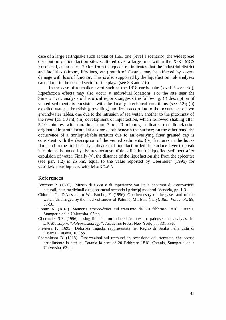
Extensive liquefaction effects occurred in the Catania area following theJanuary 11 mainshock. Probably due to the severity of the earthquake (Ms = 7.0, Io =X-XI MCS; see sub-sect. 1.2), contemporary sources tended essentially to describethe catastrophic consequences of damage suffered by the towns, providing onlygeneric information on seismogeological effects among which the liquefaction-induced features. In particular Boccone (1697) reported the widespread occurence ofventing of water to the surface in the Catania plain (Fig. 2.12, site 1), issuing fromswales and long linear fissures:
“In the plain and the territory of Catania in more than fifty places thereappeared holes, from which sprang ample sources of water, mixed with sand, butceased to flow 12 hours after the earthquake of the 11th as if they were connectedwith a large well, or with the sea itself, by the newly made fissures in the Earth […]In the Catania plain it is said that from one of these very long fissures, four or moremiles from the sea, salt water sprang as if the very same water from the sea”.
In addition Privitera (1695) supplied a description of liquefaction for the areanear the Simeto river:
“At the very time of the earthquakes, were to be seen in most parts of theCatania plain […] spouting streams of water, rising up to 10 canne high, throwingout also sulphur; forming sand hills, this occurring beyond the Simeto river”.
2.5.2The February 20, 1818 earthquake
More detailed descriptions of liquefaction features are available for the 1818earthquake, both because of the greater attention devoted to the scientificinvestigation of natural phenomena in general and of the lesser impact of this shockon the land (Ms = 6.2, Io = IX MCS, see sub-sect. 1.2). Longo (1818) reportedevidence for liquefaction-induced features in two areas near Catania: (i) in theoutskirts of Paternò, 18 km west of Catania, and (ii) in the Catania plain. The first

43
site (Fig. 2.12, site 2), locality Salinelle (37.573 lat. N, 14.889 long. E), is not ofstrict interest for the project since it is located beyond Catania’s communeboundaries. Here, sand blows observed during the 1818 earthquake cannot beascribed to real liquefaction features but to well-known phenomena of secondaryvolcanism characterised by continuous eruptions of water and CO2 leading to thetypical mud volcanoes (Chiodini et al., 1996), with paroxysms often in connectionwith seismic or volcanic activity.
On the contrary, features observed in the Catania plain site (Fig. 2.12, site 3),locality Paraspolo (37.404 lat. N, 15.089 long. E) 1 km east of the road SS114 nearthe mouth of the Simeto river, are clearly related with earthquake-inducedliquefaction. The area affected by liquefaction, apparently rather limited, is located inthe littoral zone 300 m from the sea, along the transitional strip separating the sandydeposits of the shore from the silty-clayey sediments which extensively outcrop inthe floodplain (see 2.2). Fissuring and venting took place in recent-Holocene terrains.Field observations by Longo (1818) also provide information on the development ofliquefaction:
“ Worthy of further comment however, is the phenomenon which occurred inthe estate of the Duke of Misterbianco known as Paraspolo not far from the Simeto.Five or six minutes after the earthquake there suddenly sprang forth 14 jets of water,arising up to 6 palms (about 1.5 m) creating a considerable clamour. These jetsencompassed an area of about 20 canes (40 m). The water emanated was salty. Thejets lasted for about 20 minutes and gradually diminished until they disappeared.Around the holes of 2/3 of a palm in diameter (17 cm) remained quite covered insand which on analysis comprised only quartz, silicate sand and calcium carbonate,
Augusta
MT. ETNA
Lentini
0 15 km
1
2
3
3a)
b)
Figure 2.5.1 a): location of the 1693 (horizontal bars) and 1818 (stars) liquefaction sites and related seismicsources (solid lines). 1, approximate boundary of the Catania plain; 2, Salinelle of Paternò; 3, Paraspolo. b):topographic map showing the location of the Paraspolo site.
Ionian Sea
1818
CATANIA
1693

44
all impregnated with muriatic soda1. The limestone-clay soil there is about 20 palms(5 m) above sea level, and is 150 canne from the beach (310 m). One of these ventsvisited by our Professor of Botany D. Ferdinando Cosentino on Sunday 22 Februarywas still so hot as to not allow him to suffer the heat on his naked arm which whenremoved was hot and damp. He was not able to measure the temperature for the lackof a thermometer; but the steam coming out well indicated that it must have beenvery high2. A fissure in the land was also notable not longer than 6 palms (1.5 m),and four fingers wide (32 cm), which reached as far as the above mentioned sealevel, from which it is unknown what came out. Some time afterwards the peasants inthe near dwellings heard a loud din like a thunder clap, and thinking that some wallshad fallen they went to various houses to inspect them. The following day they foundthat in the storehouse the cement floor made of lime and crushed brick wascompletely separated from the walls and split in various directions; but they did notobserve any cracks in the walls”.
A similar description of the Paraspolo site is also reported by Spampinato(1818):
“Eight to ten minutes after the strike of the earthquake of 20 February, in theestate of the Duke of Misterbianco, where the land is limestone-clay, not far from theSimeto, one saw 14 jets of water gushing forth, according to some, to the height ofabout 6 palms (1.5 m), and in the space of 7 or 8 minutes, decreasing and ceasing.The water coming out was certainly sea water; it had all the properties and the sea isnot far from this location. In addition, the area around the vents from which sprangthe water, remained quite covered in sand which when analysed showed all thecharacteristics of sand which is found on the beach, having however a bitumen-likeodour and a blackish colour”.
2.5.3Conclusion
Information reported in historical sources confirms that the alluvial region ofthe Catania plain is quite susceptible to the occurrence of liquefaction phenomenanot only during strong (Ms ≈ 7.0) but also during moderate shaking (Ms = 6.2). In the
1 “ Sand gathered from a number of holes has certain particularities which distinguish itfrom others. It has the following characteristics: it is notably finer and more powdery, lesscoarse to the touch, it is a yellowish colour, scarce in quartz, abundant in calciumcarbonate, and placed on hot coals it crumbles less, and gives off an odour of a burnt animalsubstance. I would not know with certainty where this empyreumatic smell comes from;perhaps from a little bitumen oil”.2 “ The above cited Professor of Botany observed on location that the plants, which hadbeen watered by the salt water sprung from the vents, quickly dried up, except those nearonly three holes, which although of the same species were growing prosperously. Thiscircumstance would lead to suspect that salt water did not spring from these three vents, butrather fresh river water, which from there is not further than 60 paces (50 m)”.
45
case of a large earthquake such as that of 1693 one (level 1 scenario), the widespreaddistribution of liquefaction sites scattered over a large area within the X-XI MCSisoseismal, as far as ca. 20 km from the epicentre, indicates that the industrial districtand facilities (airport, life-lines, etc.) south of Catania may be affected by severedamage with loss of function. This is also supported by the liquefaction risk analysescarried out in the coastal sector of the playa (see 2.3 and 2.6).
In the case of a smaller event such as the 1818 earthquake (level 2 scenario),liquefaction effects may also occur at individual locations. For the site near theSimeto river, analysis of historical reports suggests the following: (i) description ofvented sediments is consistent with the local geotechnical conditions (see 2.2); (ii)expelled water is brackish (prevailing) and fresh according to the occurrence of twogroundwater tables, one due to the intrusion of sea water, another to the proximity ofthe river (ca. 50 m); (iii) development of liquefaction, which followed shaking after5-10 minutes with duration from 7 to 20 minutes, indicates that liquefactionoriginated in strata located at a some depth beneath the surface; on the other hand theoccurrence of a nonliquefiable stratum due to an overlying finer grained cap isconsistent with the description of the vented sediments; (iv) fractures in the housefloor and in the field clearly indicate that liquefaction led the surface layer to breakinto blocks bounded by fissures because of densification of liquefied sediment afterexpulsion of water. Finally (v), the distance of the liquefaction site from the epicentre(see par. 1.2) is 25 km, equal to the value reported by Obermeier (1996) forworldwide earthquakes with M ≈ 6.2-6.3.
ReferencesBoccone P. (1697)., Museo di fisica e di esperienze variate e decorato di osservazioni
naturali, note medicinali e ragionamenti secondo i principj moderni. Venezia, pp. 1-31.Chiodini G., D'Alessandro W., Parello, F. (1996). Geochemestry of the gases and of the
waters discharged by the mud volcanoes of Paternò, Mt. Etna (Italy). Bull. Volcanol., 58,51-58.
Longo A. (1818). Memoria storico-fisica sul tremuoto de' 20 febbraro 1818. Catania,Stamperia della Università, 67 pp.
Obermeier S.F. (1996). Using liquefaction-induced features for paleoseismic analysis. In:J.P. McCalpin, “Paleoseismology”, Academic Press, New York, pp. 331-396.
Privitera F. (1695). Dolorosa tragedia rappresentata nel Regno di Sicilia nella città diCatania. Catania, 105 pp.
Spampinato B. (1818). Osservazioni sui tremuoti in occasione del tremuoto che scosseorribilmente la città di Catania la sera dè 20 Febbraro 1818. Catania, Stamperia dellaUniversità, 63 pp.

46
2.6 Liquefaction potential of saturated sand deposits in the urban area ofCatania(T.Crespellani, E.Cascone, F.Castelli, S.Grasso, M.Maugeri, G.Vannucchi)
2.6.1 SPT-based evaluation of liquefaction potential
One of the most common parameters for estimating soil resistance toliquefaction is the number of blows N obtained from standard penetration tests. Infact the NSPT- value, not only reflects the soil relative density and the soil fabric, butalso allows to estimate soil shear strength in undrained conditions. In addition to that,a large number of case histories of earthquake-induced soil liquefaction have beeninterpreted using SPT data, making it possible the development of reliable empiricalcorrelations between soil resistance to liquefaction and SPT values.
Two procedures, based on SPT data, have been applied to evaluate theliquefaction potential of five sites located in the municipal area of Catania. Actually,eleven potentially liquefiable sites have been identified within the municipalboundary, but only for five of them SPT data was available. The sites are shown bythe arabic numerals in Figure 2.13, and the sites for which SPT data was availableare nos. 1, 3, 4, 10 and 11. The procedures employed for the evaluation of theliquefaction potential are those due to Iwasaki et al. (1978), and Robertson andWride (1997); the former authors introduce a liquefaction potential index PL withvalues ranging between 0 and 100. Low risk is for PL < 5, and high risk for 5 < PL <15.
The results expressed in terms of risk level are given in Figure 2.13 Among theinvestigated sites, only site no. 11 has a liquefaction potential index greater than 5,corresponding to a high risk level.
The single boring available for site no.1 indicates that the local soil depositconsists of a silty sand layer 15 m thick. At site no. 3 three borings were available,and SPT tests were carried out in all of them; the data allow to distinguish a layer ofsilty sand (10-15 m thick) resting on a clayey soil. At site no. 4 two borings wereavailable, with SPT test data. The profile obtained from the borings showed that thesoil deposit consists of clayey sands, for which the development of liquefaction isunlikely; thus, the liquefaction potential PL is close to zero for this site. At site no. 10only one boring existed, showing a layer of sand (14 m thick) resting on a layer ofclayey sand. The evaluation of the liquefaction potential index for this site resulted inPL ≅ 0 because of the high value of NSPT (>40).
At site no.11 eight borings, that is nos. 418÷425 in the boring database theproject (see 2.2 above), were available together with SPT data. Near the borings,eleven CPT tests had also been carried out. The subsoil exploration revealed thepresence of a sand layer with a fine content FC < 30% down to a depth of about 10m. The SPT profiles for borings 418 and 425 are shown in Figure.2.14a and 2.15arespectively. The liquefaction potential index PL, is greater than 5 (Figure 2.14b and2.15b).

47
Very low risk Low risk High risk No data
Figure 2.13 – Map of the risk of liquefaction within the Catania municipality. Arabic numeralsdenotes sites with SPT data.
Figure 2.14 - Site 11, boring n.418: a) NSPT profile; b) liquefaction potential index.
0,00
5,00
10,00
15,00
20,00
0 10 20 30 40 50
NSPT
Dep
th.[m
]
0,00
2,00
4,00
6,00
8,00
10,00
12,00
14,00
16,00
18,00
20,00
0 2 4 6 8 10
Liquefaction potential index (P L)
Dep
th.[m
]
Iwasaki et al.
Robertson & Wride

48
Figure 2.15 - Site 11, boring n.425: a) NSPT profile; b) liquefaction potential index.
Finally a parametric analysis has been performed to investigate the influence ofthe maximum ground acceleration, amax, on the liquefaction potential index computedaccording to Robertson and Wride (1997). In Figure 2.16, for the borings of siteno.11, the variation of PL with depth is plotted for amax ranging from 0.30g to 0.45g.Such results clearly demonstrate that the ground acceleration is a crucial parameter: a0.1g increase of amax produces in fact a doubling of PL
Figure 2.16 - Parametric analysis: a) boring n. 418; b) boring n. 425
0,00
5,00
10,00
15,00
20,00
0 10 20 30 40 50 60
NSPT
Dep
th.[m
]
0,00
2,00
4,00
6,00
8,00
10,00
12,00
14,00
16,00
18,00
20,00
0 2 4 6 8 10
Liquefaction potential index (P L)
Dep
th.[m
]
Robertson & Wride
Iwasaki et al.
0,00
5,00
10,00
15,00
20,00
0 5 10 15 20Liquefaction potential index (P L)
Dep
th.[m
]
0,30g 0,35g 0,40g 0,45g
0,00
5,00
10,00
15,00
20,00
0 5 10 15 20Liquefaction potential index (P L)
Dep
th.[m
]
0,30g 0,35g 0,40g 0,45g

49
2.6.2 CPT-based evaluation of liquefaction potential
Cone penetration testing (CPT) is not significantly affected by test equipment,and also allows to obtain a more continuos data profile than standard penetrationtesting. For these reasons, methods assessing the soil resistance to liquefaction basedon CPT data have been developed in the last decade. The most credited among theseprocedures is at present the Robertson and Wride (1997) method in its most up-todate version.
Eleven CPT tests are available for site no.11, which is located in the area calledSan Giuseppe La Rena, near the seashore and the airport. The site consists of alluvialdeposits resting on a very thick clay formation (see 2.2).
Figure 2.17 provides a plot of the liquefaction potential index for CPT no.1(located near borehole no.425 of the boring database) which attains the maximumvalue 6.73 at a depth of 10.4 meters. Therefore, for the first level scenario groundmotions, the liquefaction risk must be considered to be high, since the threshold PL =5 is exceeded.
It is reminded that in this project the first-level scenario ground motions havebeen deterministically estimated (see 3. below), having in mind a possible repetitionof the catastrophic 1693 earthquake, and that a second-level scenario was alsoconsidered for events of less severity, and a shorter return period. For the latter, thedamaging earthquake that occurred in 1818 was used as reference. Since in bothcases considerable uncertainties inevitably exist on the values of the seismicparameters, a parametric analysis was carried out to clarify the influence of theearthquake magnitude and of the peak acceleration amax on the liquefaction potentialindex PL. The results obtained are shown in Figure 2.18 and in Table 2.4. Formagnitude M lower than 6.5, and a maximum acceleration lower than 0.5g, theliquefaction risk is low. For more severe earthquakes, the liquefaction risk can behigh, but never very high.
Table 2.4 - Effect of earthquake magnitude M and of amax on the liquefaction potential index PL.
M 5.0 5.5 6.0 6.5 7.0 7.5 8.0 8.5amax/g0.100.150.200.250.300.350.400.450.50
0.080.200.300.44
0.030.200.320.530.881.26
0.070.260.490.911.422.153.13
0.010.270.571.202.053.274.415.47
0.220.571.342.594.105.426.677.78
0.030.431.262.794.566.137.558.9010.05
0.180.812.244.406.267.919.4310.6511.63
0.311.403.755.977.939.6711.0112.0612.89

50
-20
-15
-10
-5
0
0 5 10 15 20
PL
z (m
)
0
5
10
15
20
0 0.1 0.2 0.3 0.4 0.5 0.6
(amax/g)
P L
M = 5
M = 5.5
M = 6
M = 6.5
M = 7
M = 7.5
M = 8
M = 8.5
Figure 2.17 - Liquefaction potential index PL
for CPT n.1.Figure 2.18 – Effect of magnitude and of amax onthe liquefaction potential index PL.
2.6.3 Conclusions
Information from historical sources confirms that the alluvial deposits of theCatania plain have suffered liquefaction effects in past earthquakes not only for verystrong shaking (Ms ≈ 7.0) but also for a moderate one (Ms = 6+), as reported in 2.5.On the other hand, the results obtained from site response analyses using in situ Vsmeasurements (see 2.3) show that there is a high probability of liquefaction in thearea of the Plaja beach for the first-level scenario earthquake.
In our study, the results obtained from the SPT data (Par. 2.6.1) allow us todraw the following conclusions: the occurrence of liquefaction at sites no.2, 5, 6, 7, 8and 9 cannot be evaluated because further investigations are required; liquefaction atsite no.4 (originally included among the liquefiable sites) is very unlikely due to thehigh clay content; the liquefaction risk at site no. 10 is very low due to the high soilstrength; the liquefaction risk at sites no.1 and 3 is low and occurs only at depthsgreater than 10 m. Finally, liquefaction under the scenario earthquake at site no.11, inthe area called San Giuseppe La Rena, is high both according to the SPT and to theCPT procedures, and is relevant across the whole thickness of the sand layer.
The results obtained from the SPT data for site no.11 using the Robertson andWride (1997) method compare well with those based on CPT data from the samesite. Finally, the parametric analysis showed that the value of the maximum groundacceleration strongly affects the liquefaction potential index.

51
ReferencesIwasaki T., Tatsuoka F., Tokida K., Yasuda S. (1978). A practical method for assessing soil
liquefaction potential based on case studies at various sites in Japan, Proceedings 2nd
International Conference on Microzonation for Safer Construction, Research andApplication, San Francisco, California, Vol.2, pp.885-896.
Robertson P.K., Wride (Fear) (1997). C.E., Cyclic liquefaction and its evaluation based onSPT and CPT, Final Contribution to the Proceedings of the 1996 NCEER Workshop onEvaluation of Liquefaction Resistance, Salt Lake City, Utah.
Catania Project Report, National Research Council-National Group for the Defence AgainstEarthquakes in cooperation with the municipality of Catania (in Italian), 1997.
2.7 Conclusions(M. Maugeri and E. Faccioli)
The creation of a database of about 860 boreholes has allowed to make a first,realistic geotechnical zonation of the urban area of Catania, includingcharacterisation of geotechnical units with strength parameters and mapping of theaverage S wave velocity Vs,30 for earthquake engineering purposes (2.2). Thedatabase includes borehole locations and profiles accessible via GIS, can becontinuously updated, and is a powerful tool for seismic microzonation. Specialinvestigations were carried out for better characterisation of the soil behaviour underthe strong ground shaking generated by the first-level scenario earthquake.
Vs profiles with depth have been additionally obtained for some representativelocal soils by surface wave techniques. Surprisingly, at 15 m depth at one locationthe Vs values (150 m/s) in the 1669 lava flow were found to be lower than in theshore sands (280 m/s). The highest velocities (450 m/s) have been measured in theconglomerates (unit SG), while the Vs values in some near-surface prehistoric lavasrank between those of incoherent soils (shore sands) and stiff soils (conglomerates).This would suggest that the seismic basement to be assumed for seismic responseanalyses in Catania should be taken deeper than 15 m in the city centre, deeper than30 m for the fluvial deposits (conglomerates and sands), and deeper than 20 m for theshore sands (see 2.3). However, more measurements are needed to draw a firmconclusion, especially in some city areas
Under strong ground motions such as those expected in the scenario earthquakethe soil behaves non-linearly. Non-linear soil behaviour of the clay in the Cataniacentral area (unit ASg) has been investigated by cyclic laboratory tests onundisturbed samples retrieved from one borehole (see 2.4). The values of the small-strain shear modulus measured by laboratory tests are in good agreement with thoseevaluated from in situ down-hole tests. The shear modulus degradation for this clayis close to that evaluated for the Piana di Catania clay (geotechnical unit Alf). Thesmall-strain damping ratio evaluated by cyclic torsional tests is about 1%,considerably less than the value of about 4% evaluated by resonant column tests.

52
Information from historical sources confirms that the alluvial deposits of theCatania plain are susceptible to liquefaction. The distribution of liquefaction sitesover a large area within the X-XI MCS isoseismal of the 1693 destructiveearthquake, as far as some 20 km from the epicentre, indicates that the industrialdistrict and the airport area south of Catania may be affected by severe liquefactiondamage, with consequent loss of their function (2.5).
Therefore, liquefaction potential analyses have been performed. The resultsbased on data coming from Vs measurements show that there is a high probability ofliquefaction in the area of the Plaja beach for a scenario earthquake of magnitude 7(see 2.3). The results obtained from standard geotechnical analyses with SPT datashow that the liquefaction risk is high for one area near the seashore (San GiuseppeLa Rena); this indication is in good agreement with the procedure based on CPT data(see 2.6).