evaluation of thermal spray coatings and shape memory...
TRANSCRIPT

GRC Transactions, Vol. 37, 2013
87
KeywordsElastomer, Thermal Spray, HVOF spray, twin-wire arc spray, oxides, Shape Memory Alloys
AbstrAct
Geothermal and deep oil/gas applications require downhole tools to operate at high temperatures (in excess of 300 °C (572 °F) in some cases) and pressures greater than 15,000 psi (1034 bar). Traditional elastomer o-ring seals are commonly used and are adequate for short term deployments at moderate pressures and temperatures but fail at these extreme conditions especially if the tools are deployed for more than a few hours. Elastomer choices for downhole tools include fluoroelastomer (Viton® A), AFLAS and others with similar chemistry but optimized for specific ap-plications. All of the traditional elastomers have a manufacturer’s recommended maximum temperature of approximately 200 °C (392 °F). Less common and considerably more expensive is the perfluoroelastomer (Kalrez® Spectrum 7090) class of O-rings. They are rated by the manufacturer to operate up to 325 °C (617 °F). While they have a high temperature rating, they have a high compression set when they are exposed to temperatures above 300 °C (572 °F) which creates an issue in high pressure applica-tions. Metal-to metal sealing techniques, such as metal c-rings, can tolerate this harsh environment but cannot be used in all seal designs. This study focuses on using Thermal Spray and Shape Memory Alloys (SMA) to possibly replace elastomers, and also serve as an additional backup seal to both traditional o-rings and metal c-rings.
Introduction
Elastomer O-rings have been the seal of choice in downhole tools but as the need increases to access hotter geothermal and deep oil/gas reservoirs, these seals are marginal and in some cases inadequate to handle the higher temperatures when combined with high pressures. Pressure seals are required for all electronic downhole tools and seal failures can lead to severe tool damage to
the electronics. In addition, high temperature electronics capable of operating continuously at temperatures of 250 °C (482 °F) and higher are available and greatly extend the time the tools are exposed to these extreme conditions. Traditionally, electronics are placed in a Dewar flask that thermally protects the electronics from heat but limit the time the electronics can stay in the well. As such, the seals have limited exposure and are replaced after every deployment. Using high temperature electronics, long term deployments (months even years) are possible and in these applications any leak will lead to tool failure.
Thermal Spray is a group of coating processes which include plasma spray, wire-arc spray, flame spray, high-velocity oxy-fuel spray (HVOF), and detonation gun spray. Each of these processes uses either an electrical or combustion energy source to soften or liquefy the coating material, powder, wire, or rod, into small droplets or particles (Figure 1). These droplets or particles are then accelerated and propelled onto a prepared surface using pro-cess gases or atomization jets. At impact, the softened or molten coating material is significantly transformed into thin layers (-1 to 20 µm) called “splats” that deform and adhere to the substrate surface (Figure 2). The splats generally cool at accelerated rates (>106 Kelvins/s for metals) and are uniform, very fine grained, polycrystalline coatings or deposits. Sprayed deposits contain some level of porosity, oxide inclusions, unmelted or partially melted particles, and entrained air (Figure 3). (ASM Thermal Spray Society, 2004, p. 3).
Evaluation of thermal spray coatings and shape Memory Alloys as Pressure seals for Downhole tools
Dennis King1 and Joe Henfling
1sandia National Laboratories
Detonation-Gun Spray
H.V.O.F.Spray
FlameSpray
Wire-ArcSpray
PlasmaSpray
Chemical (Combustion)Heat Source
ElectricalHeat Source
Thermal Spray Processes
Figure 1. Thermal Spray Processes. (Flame Spray Inc.)

88
King and Henfling
Based on experience and recommendations from Sandia National Laboratories’ thermal spray department and a supplier of these services, Thermal Spray Solutions, the spray processes and type of coatings were selected. The selection criterion for the coatings was based on a need to have a material that could withstand some wear and exhibit high corrosion resistance. Table 1 provides a list of processes and coating materials that were selected. Preference was given to processes adaptable for field application of the coating, thus enabling field repair of the downhole tool.
table 1. Coating Materials and Processes.
Coating Material Process
Inconel (Ni 328) HVOF
Metco 5803 (WC-Co) HVOF
Ni Al Twin Wire Arc Spray
Bondarc Wire-75B, 95% Nickel/5% Aluminum Twin Wire Arc Spray
Nickel Wire-06T, 99% Nickel Twin Wire Arc Spray
Moly Wire-13T, 99% Molybdenum Twin Wire Arc Spray
Stainless Steel-316L Cold Spray
Colmonoy 69 SC, 70% Nickel 17% Chromium HVOF
Shape Memory (NiTi) Alloys (SMA) were discovered in 1962 and have been used in various military equipment, aerospace applica-tions, and weapon designs since the early 1970’s. These alloys are able to withstand static loading, fatigue, high temperature exposure, thermal cycling, and offer good corrosion resistance which make them a good fit for geothermal applications (Bor-den, Use of Shape Memory Alloys in High Reliability Fastening Applications, 2003). The NiTi alloys exhibit a unique ability to recover their shape when a specific temperature is applied to the alloy. This property is very different than thermal expansion. This unique effect is produced by a crystalline phase change called martensitic transformation. The transformation occurs over a range of temperature, above which the material is in the austenitic phase and below which the material is in the martensitic phase (Figure 4). (Borden, Shape-Memory Alloys: Forming a Tight Fit, 1991, pp. 66-68)
The Shape Memory material that was selected for our testing is known as a heat-to-recover (HTR) alloy. This means at room temperature the alloy is in the expanded state (martensitic phase) and begins the transformation to the contracted state (austenitic phase) at 45°C (113 °F). This transformation is complete at 165 °C (329 °F) and at that temperature the alloy has fully recovered to its original memory shape and will retain that shape until the temperature is lowered to -100 °C (-148 °F). While in the origi-nal memory shape the alloy will exert a clamping force on the substrate that can be calculated based on the alloy size, shape and the gap distance between the ring and the substrate. The nominal clamping force for the 1-3/4” SMA rings that were used during this test is 38,620 lbs. .
thermal spray testing and resultsSetup
There were two different types of 304L stainless steel test samples used for the experiments. The first was a simple design made from two pieces of stainless steel that could be screwed together to form a tool joint. The second was an actual 1-3/4”
Figure 2. Scheme of the thermal sprayed coatings process. (Key to Metals AG 2013).
Figure 3. Schematic cross-section of thermally sprayed layer. (Flame Spray Technologies).
Figure 4. Microscopic Diagram of the Shape Memory Effect. (2001 SMA/MEMS Research Group).
89
King and Henfling
OD tool joint design that has been used in many of Sandia’s downhole tools.
When the two tool sections are assembled a metal to metal contact point is created and when tightened could form a seal, which could skew the results of the thermal spray seal testing. In order to isolate the effectiveness of the applied seal and alleviate the possibility of a seal being formed along this contact point, 50 grit sandpaper was used to pre-condition the face of the female sec-tion and the two sections were only torqued to 25 ft/lbs (Figure 5).
Holes were drilled in the interior of the samples to form a cav-ity. This cavity allowed space for water or oil to enter if the joint leaked during the test. The amount of leakage was determined by weighing the mock tool before and after each test. A non-coated control sample was tested along with the coated samples. The mock tools were grit blasted with size 24 aluminum-oxide grit and cleaned with acetone and alcohol rinse before each spray applica-tion. After the thermal spray application was completed the mock tools were weighed and placed in a pressure chamber filled with water and pressurized to 5,000 psi (354 bars). The hydrostatic test lasted for a minimum of four hours, but some were held at test pressure for as long as 10 days. The variation in the time for the tests was to ensure that the samples were not leaking before the next test sequence was initiated. Once the hydrostatic test had been completed, the samples that did not leak were subjected to a pressure/temperature test.
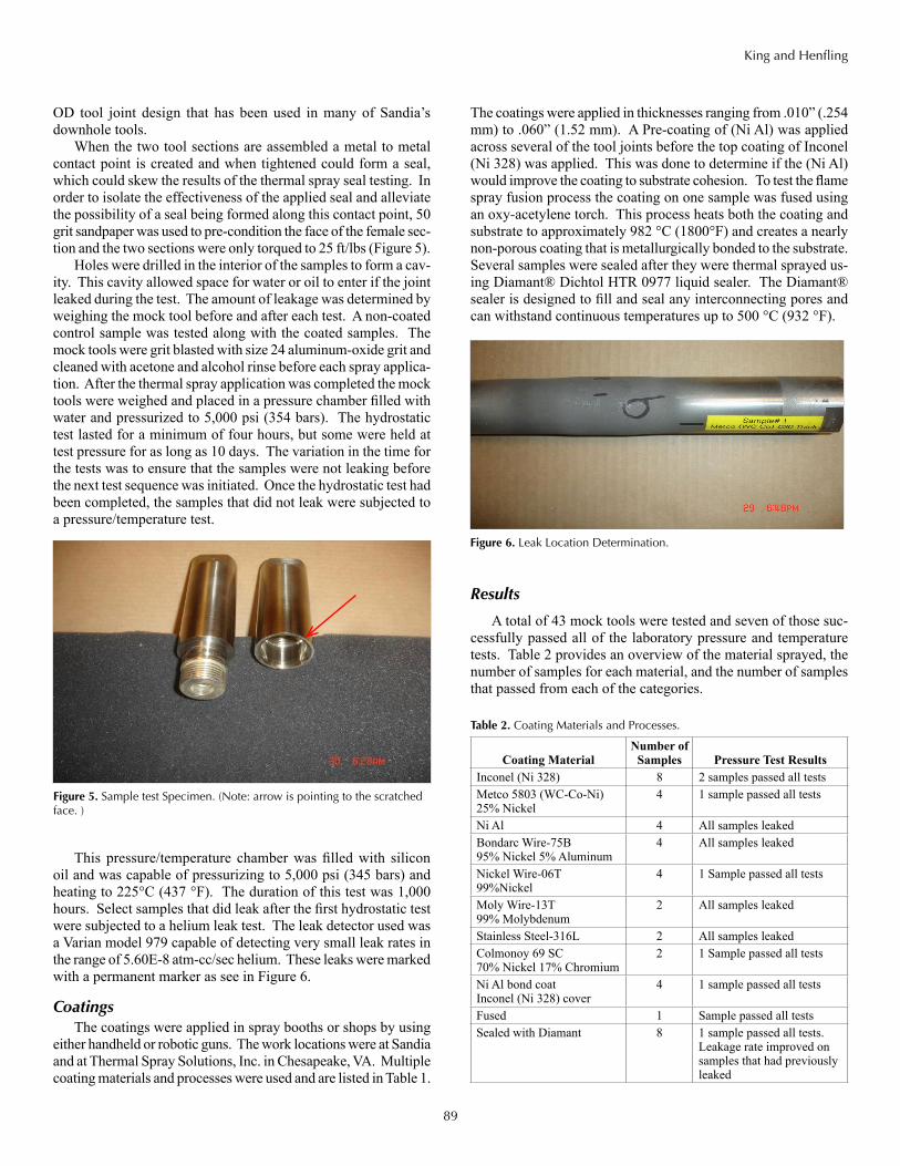
This pressure/temperature chamber was filled with silicon oil and was capable of pressurizing to 5,000 psi (345 bars) and heating to 225°C (437 °F). The duration of this test was 1,000 hours. Select samples that did leak after the first hydrostatic test were subjected to a helium leak test. The leak detector used was a Varian model 979 capable of detecting very small leak rates in the range of 5.60E-8 atm-cc/sec helium. These leaks were marked with a permanent marker as see in Figure 6.
CoatingsThe coatings were applied in spray booths or shops by using
either handheld or robotic guns. The work locations were at Sandia and at Thermal Spray Solutions, Inc. in Chesapeake, VA. Multiple coating materials and processes were used and are listed in Table 1.
The coatings were applied in thicknesses ranging from .010” (.254 mm) to .060” (1.52 mm). A Pre-coating of (Ni Al) was applied across several of the tool joints before the top coating of Inconel (Ni 328) was applied. This was done to determine if the (Ni Al) would improve the coating to substrate cohesion. To test the flame spray fusion process the coating on one sample was fused using an oxy-acetylene torch. This process heats both the coating and substrate to approximately 982 °C (1800°F) and creates a nearly non-porous coating that is metallurgically bonded to the substrate. Several samples were sealed after they were thermal sprayed us-ing Diamant® Dichtol HTR 0977 liquid sealer. The Diamant® sealer is designed to fill and seal any interconnecting pores and can withstand continuous temperatures up to 500 °C (932 °F).
Results
A total of 43 mock tools were tested and seven of those suc-cessfully passed all of the laboratory pressure and temperature tests. Table 2 provides an overview of the material sprayed, the number of samples for each material, and the number of samples that passed from each of the categories.
Figure 5. Sample test Specimen. (Note: arrow is pointing to the scratched face. )
Figure 6. Leak Location Determination.
table 2. Coating Materials and Processes.
Coating MaterialNumber of
Samples Pressure Test ResultsInconel (Ni 328) 8 2 samples passed all testsMetco 5803 (WC-Co-Ni) 25% Nickel
4 1 sample passed all tests
Ni Al 4 All samples leakedBondarc Wire-75B 95% Nickel 5% Aluminum
4 All samples leaked
Nickel Wire-06T 99%Nickel
4 1 Sample passed all tests
Moly Wire-13T 99% Molybdenum
2 All samples leaked
Stainless Steel-316L 2 All samples leakedColmonoy 69 SC 70% Nickel 17% Chromium
2 1 Sample passed all tests
Ni Al bond coat Inconel (Ni 328) cover
4 1 sample passed all tests
Fused 1 Sample passed all testsSealed with Diamant 8 1 sample passed all tests.
Leakage rate improved on samples that had previously leaked

90
King and Henfling
The spray parameters for the seven samples that passed are listed in Table 3. It should be noted that:
• Samples 1, 5, 6, 7, & 9 were sprayed using the HVOF process.
• Sample 10 was sprayed with Nickel Wire-06T using the electric arc spray process also called twin-wire arc.
• Sample 4 was sprayed with a self-fluxing alloy using a flame spray process called combustion powder spraying. The coating was then fused with an oxy-acetylene torch.
• Sample 1 had a Ni/Al bond coat sprayed over the joint be-fore a cover pass of Metco 5803 (WC-Co-Ni) was sprayed.
Discussion
Five thermal spray processes were evaluated and three of those produced promising pressure seals. These three processes are HVOF, twin-wire arc and fused flame spray. Of these pro-cesses, the HVOF process was the most successful. There is some difficulty however in getting uniform coatings as illustrated in the two micrographs below. Figure 6 has an average poros-ity of .19% and an oxide content of 1.33% and Figure 7 has an average porosity of .23% and an oxide content of 22.99%. The oxide inclusions are dark elongated phases that appear in strings in the coating cross section. The average oxide content
for the 6 samples that were micrographed is 15.65%. Oxide inclusions are often considered detrimental to coating proper-ties. It has been found that oxide inclusions add to the hardness of the coating, since oxides have hardnesses exceeding 1000 Diamond Pyramid Hardness (DPH). Therefore, the composite mixture of the metal and metal oxides becomes harder than the metal coating itself. This increased hardness can lead to brittle coatings, because oxides fracture easily. If too concentrated, the oxides may interfere with splat-to-splat cohesion, leading to decreased cohesion strength of the coating. (ASM Thermal Spray Society, 2004, p. 48) The presence of large quantities of oxide combined with the occurrence of normal porosity could be creating the leak paths that were detected with the helium leak tester (Figure 6). This HVOF process would be the most difficult to use in the field because of the amount of specialized equipment required. The coatings could successfully be applied in a lab or shop setting but more extensive testing will need to be done to minimize the number of oxide inclusions by altering spray parameters.
table 3. Spray parameters for samples that passed the pressure/tempera-ture tests.
Sample # 1 4 5 6 7 9 10Process Type
HVOF X X X X XTwin Wire Arc X XPlasma Spray X
MaterialInconel (Ni 328) X XMetco 5803 (WC-Co-Ni) X X
Nickel Wire-06T XColmonoy 69 SC XNi/Al Bond coat XFused XSealed with Diamont X
Coating ParametersGun to work dis-tance 11" 9.5" 11" 11" 9.5" 11"
Surface feet/minute
Preheat temperature 212- 302 °F
212- 302 °F
212- 302 °F
212- 302 °F
212- 302 °F
212- 302 °F
212- 302 °F
Max temperature ≈ 250 °F
1,800 °F
≈ 250 °F
≈ 250 °F
≈ 250 °F
350 °F
≈ 250 °F
Spray rate lbs./hr.# of passes 9 60 10
Thickness per pass 0.00034 0.021
Coating ThicknessStarting diameter (inches) 1.448 1.449 1.4645 1.467 1.5 1.5175 1.492
Final diameter (inches) 1.4885 1.469 1.499 1.5075 1.551 1.5595 1.514
After finished (inches) 0.020 0.010 0.017 0.020 0.026 0.021 0.011
Figure 7. Micrograph of a Ni-328 Coating Average Porosity of .19% and an Oxide Content of 1.33%).
Figure 8. Micrograph of a Ni-328 Coating Average Porosity of .23% and an Oxide Content of 22.99%.

91
King and Henfling
Only one of the twin-wire arc coatings appeared to be a promising choice for coating downhole tools. One of the first samples sprayed passed all of the tests but we were unable to reproduce another of the same quality. It’s possible that this one sample passed because of a metal to metal face seal that was created when the two mock tool halves were torqued together using a force of 125 ft/lbs. After this realization the procedure was changed to a torque of 25 ft/lbs and pre-conditioning the face with 50 grit sand paper. The advantages of twin-arc is that the equipment can be easily transported to a field site, the coating is applied at a low temperature which in turn keeps the substrate cool, and the materials are relatively inexpensive. The biggest disadvantage is that the coating porosity is high, and it is difficult to produce a coating that will not leak when exposed to high pressures.
The Flame spray (fused) process forms a positive seal over the tool joint but the 982 °C (1,800 °F) temperature required to fuse the coating will damage any electronics in close proxim-ity. The resulting seal is similar to a welded joint and in reality, welding would be a more cost effective solution. Both the fused flame spray coating and welding potentially over-heats the tool’s internal components and would require an elaborate cooling system to help prevent damage to the electronics. This approach is not practical and as such, these processes are not the preferred sealing method. The other thermal spray processes deposited the coating with minimal heat to the tool housing, thus not damaging the electronics or redundant elastomer seals. Testing was performed on four samples to determine if the fusion could be done at a lower temperature, but the tests were unsuccessful due to the spray material separating from the substrate. The substrate and the coating need to be at the same temperature for the fluxing action to occur.
shape Memory Alloy testing and resultsSetup
The SMA testing utilized two different mock tool designs. The first was a generic design that had a 1” OD to accommodate an off the shelf SMA ring. This ring was purchased from Intrin-sic Devices, Inc., part number AHE 1010-0141-0400 and has a nominal clamping force of 8720 lbs. Later testing used the tool joint design as shown in Figure 5. An SMA ring from Intrinsic Devices, Inc., part number of AHE1780-0250-1000CP, with a nominal clamping force of 38,620 lbs. was used on these mock tools. This ring had a 45° chamfer on the outer edge and raised ridges machined on the ID as shown in Figure 9. The radiused ridges increase the contact pressure between the ring and the tool joint to create the seal. There were two materials used under the rings in an attempt to seal any surface scratches that may have been present on the mock tools. The materials used are Teflon® tape and lead tape. The interior of some of the rings were also plated with gold or silver to aid in the surface sealing. The procedure for installing the ring was to slide the ring over the tool joint and center it using collar clamps. The mock tool samples were then heated in an oven to 200 °C (392 °F) causing the crystalline phase change from martensite to austenite. The samples were then ex-
posed to the same hydrostatic and temperature tests as described in the thermal spray “Setup” section.
ResultsEighteen mock tools were tested with 12 passing and six failing
as shown in (Table 4). The 1” samples all had rings with smooth ID’s. The samples that passed either had gold plating, Teflon® tape or lead tape between the ring and the mock tool. Eight of the nine 1-3/4” mock tools passed all of the temperature/ pres-sure tests. The one 1-3/4” mock tool that did not pass was not gold plated, and the inner ridge had a flat spot. The flat spot was similar to the one that can be seen in the photo, (Figure 9 upper ridge left side) and appears as a dark streak.
To alleviate this problem, the ID of each ring was machined true before the ridges were subsequently machined. The gold plat-ing on the NiTi was an experimental process to select an etching compound that would properly etch the NiTi. Figure 10 shows a sample of the plating process. It can be seen that the ridges are well coated and this particular ring was used on sample 6 and passed all of the tests.
table 4. sMA test Parameters. (Several of the samples had the rings removed and new ones installed and this is indicated by 2A, 2B etc.)
Sample # 2A 2B 3A 3B 4A 4B 4C 6 7 2 3 4 5 6 10 16 17 181” mock tool X X X X X X X X X1-3/4” mock tool X X X X X X X X XSmooth ID X X X X X X X X XRidge on ring ID X X X X X X X X XGold Plating X X X X X X X XSilver Plating XTeflon Tape X XLead Tape X XPassed Pressure/Temp. Test X X X X X X X X X X X X
Failed Pressure/Temp. Test X X X X X X
Figure 9. SMA Ring. (Intrinsic Devices Inc. part # AHE1780-0250-1000CP.) The ridges on the ID of the rings were ma-chined after the parts were purchased.
Figure 10. Gold Plating on the Inner Ridges of the SMA Ring.
Contact ridge flat spot

92
King and Henfling
conclusion
Using thermal spray technology to create a pressure seal is possible, but to date has not shown consistent results. While considerable progress was made during the course of the program, the inconsistencies would need to be greatly reduced to make this a viable option for high pressure/high temperature seals. Further investigation in a controlled spray environment, such as the facility at Sandia, could help reveal and eliminate the parameters leading to the inconsistent seal performance seen during the test program. This would require an expanded testing program and was beyond the scope of this project.
The test results show that the SMA rings can be successfully used to seal tool joints and also serve as an additional backup seal to both traditional o-rings and metal c-rings. Plating the ID of the rings proved to be difficult due to the metallurgic properties of the NiTi Shape Memory Alloy. Normally the plating process uses hot chemical baths for etching, but the NiTi alloys start to change phase when the temperature is above 45 °C (113 °F). This
temperature limitation also proved difficult in machin-ing the ID of the rings. The rings had to be sufficiently cooled to prevent them from shrinking in size and being released by the hold-ing chuck. One unique feature of the SMA rings is that it they can be removed from the tool body by cool-ing. There is equipment commercially available that
could be used in the field to remove the rings as shown in Figure 11. This process utilizes liquid CO2, liquid N2, or refrigerant to cool the tool joints and rings. The rings can also be installed in the field using induction heating blankets. While we did not test either of these methodologies the information supplied by the manufacturer indicates that these methods could work for the application.
To establish the SMA ring as a viable option in tool joint sealing additional testing will be needed. There are numerous ring styles that could be designed for both internal and external applications. This paper only addressed the external ring but an internal ring could also provide an effective joint seal. Ring installation and removal in the field will also be an important part of any future testing program.
Acknowledgements
The authors would like to graciously thank DOE Geothermal Technology Program for their funding of this project. We also wish to thank Aaron Hall, Mark Grubelich, Jiann Su, Steve Knudsen, Jeff Greving, Scott Lindblom, James McCloskey, Mark Vaughn (Sandia Retired), Scott Spruce (Thermal Spray Solutions), and Tom Borden (Intrinsic Devices, Inc.) for providing their exper-tise in Thermal Spray Processes and Shape Memory Alloys and assisting in evaluating the paper. In addition we would like to thank Aaron Velasquez (Theta Plate Inc.) and his team for their support with gold plating the SMA rings. Eric Theiling (Protech Lab Corp.), Bruce D. Fishel (Sandia), Steve Bauer (Sandia), and Scott Broome (Sandia) for their support with testing.
referencesASM Thermal Spray Society. (2004). Hanbook of Thermal Spray Technology.
(J. D. Associates), Ed.) Materials Park, OH, USA: ASM International.
Borden, T. (1991, October Vol. 113/No. 10). Shape-Memory Alloys: Forming a Tight Fit. Mechanical Engineering, pp. 66-72.
Borden, T. (2003). Use of Shape Memory Alloys in High Reliability Fasten-ing Applications.
1 Joe Henfling worked for Sandia and originally initiated the project but has since retired from Sandia.
2 Sandia National Laboratories is a multi-program laboratory operated and managed by Sandia Corporation, a wholly owned subsidiary of Lockheed Martin Corporation, for the U.S. Department of Energy’s National Nuclear Security Administration under contract DE-AC04-94AL85000. SAND 2013-3748C.
Figure 11. Qwik-Freezer® COB Indus-tries, Inc.