evaluation of vibratory rollers on three types of … · 2018-11-09 · sisted of the compaction of...
TRANSCRIPT

^
1 TECHNICAL MEMORANDUM NO. 3-271 t
CD SOIL COMPACTION INVESTIGATION CO Oi
to CJD
Q
i > a
Report 10
EVALUATION OF VIBRATORY ROLLERS ON
THREE TYPES OF SOILS
by
J. W. Mall
• o p o 0 c 5 o -I 0 z i <
i > 3 March 1968 z
a M
3 a
U. S. Air Force -. 3 " "^
Conducttd by
U. S. Army Engineer Waterways Experiment Station
CORPS OF ENGINEERS Vickfburg, Mitciisippi
S < THIS DOCUMENT HAS BEEN APPROVED FOR PUBLIC RELEASE • AND SALE; ITS DISTRIBUTION IS UNLIMITED
30

·•·
THIS DOCUMENT IS BEST QUALITY AVAILABLE. THE COPY
FURNISHED TO DTIC CONTAINED
A SIGNIFICANT NUMBER OF
PAGES WHICH DO NOT
REPRODUCE LEGIBLYo

REPORTS OF THIS SERIES ENTITLED "SOIL COMPACTION INVESTIGATION" TECHNICAL MEMORANDUM HO. 3-271
Report No.
1
2
3 k
5
6
T
9 10
am DR
Mine i a.*
Title Date
Compaction Studies on Clayey Sands
Compaction Studies on Silty Clay
Compaction Studies on Sand Subgrades
Subgrade Compp ".ion Studies
Miscellaneous Laboratory Tests
Effect of Size of Feet on Sheepsfoot Roller
Effect on Sol1 Compaction of Tire Pressure and Number of Coverages of Rubber-Tired Rollers and Foot-Contact Pressure of Sheepsfoot Rollers
Effect of Lift Ihiokness and Tire Pressure
Compaction of a Graded Crushed-Aggregate Base Course
Evaluation of Vibratory Rollers on Three Types of Soils
1 ji'f zMm
r nl
«Y mmi n» «vAiumrn eate
DliT. «(All. HOM' VECUl
/
Destroy this report when no longer needed. Do not return it to the originator.
Apr 1949
July 19^9
Oct 19l»9
Feb I95O
June 1950
June I95U
June 1956
Oct 1957
Sept 1963
Mar I968
i
The findings in this report are not to be construed as an offic. Department of the Army position unless so designated
by other authorized documents.

UNCLASSIFIED
AD 667 966
SOIL COMPACTION INVESTIGATION: REPORT 10. EVALUATION OF VIBRATORY ROLLERS ON THREE TYPES OF SOILS
Jim W . Hall
Army Engineer Waterways Experiment Station Vicksburg, Mississippi
March 1968
Processed for . . .
DEFENSE DOCUMENTATION CENTER DEFENSE SUPPLY AGENCY
©[Lüi£\[K?DKl@[HK§)yS[l FOR FEDERAL SCIENTIFIC AND TECHNICAL INFORMATION
U. «. OCPARTMENT OF COMMERCE / NATIONAL BUREAU OF STANDARDS / INSTITUTE FOR APPLIED TECHNOLOGY

r v.
TECHNICAL MLMORANDUM NO. 3-271
SOIL COMPACTION INVESTIGATION Report 10 ,
EVALUATION OF VIBRATORY ROLLERS ON
THREE TYPES OF SOILS
by
J. W. Hall
oioom
«
March 1968
Sponsored by
U. S. Air Force
Conducted by
U. S. Army Engineer Waterways Experiment Station
CORPS OF ENGINEERS Vicksburg, Mississippi
t B >.- V M H .-. j i c K S Bi U n G M I S 1«
THIS DOCUMENT HAS BEEN APPROVED FOR PUBLIC RELEASE AND SALE; ITS DISTRIBUTION IS UNLIMITED

FOREWORD
This investigation is part of the continuing Air Force program
sponsored through Military Construction, Office, Chief of Engineers, for
developing construction methods and techniques for flexible pavements.
The study described herein was accomplished by personnel of the
Soils Division, U. S. Army Engineer Waterways Experiment Station, during
the period May through June 1962. Engineers actively engaged in the
collection and analysis of data were Messrs. C. D. Burns, A. H. Joseph,
and J. W. Hall. The overall study was under the general supervision of
Messrs. W. J. Turnbull, A. A. Maxwell, and R. G. Ahlvin.
Director of the Waterways Experiment Station during the conduct of
this study was COL John R. Oswalt, Jr., CE. Technical Director was
Mr. J. B. Tiffany.
iii

**■«*»,
CONTENT:
FOREWORD
CONVERSION FACTORS, BRITISH TO METRIC UNITS OF MEASUREMENT
SUMMARY
PART I: INTRODUCTION
Background Purpose and Scope
PART II: FIELD TESTS
Test Area Description of Rollers and Traffic Sequence Soils Tests Conducted
PART III: TEST RESULTS
Compactor A Compactor B Compactor C
PART 17: SUMMARY OF RESULTS, AND CONCLUSIONS
Summary of Results Conclusions
TABLES 1-5
PLATES 1-9
.Page
iii
vii
ix
1 2
3 3 k 1*
6
6 8 9
12
12 13

rt^r^ ,y .<^!.-MI!S*iiP
CONVERSION FACTORS, BRITISH TO METRIC UNITS OF MEASUREMENT
British units of measurement used in this report can be converted to metric
units as follows:
Multiply
inches
feet
pounds
pounds per square inch
pounds per cubic foot
tons
JL To Obtain
2.5^
O.3Oi)0
o.,-;5359237
0.070307
16.0185
907.185
centimeters
meters
kilograms
kilograms per square centimeter
kilograms per cubic meter
kilograms
VI3

^— ■ '^■^■'■iv- •^■.,
SUMMARY
This study was conducted for the purpose of determining the ability of vibratory rollers to compact soils. For comparative purposes, a 50-ton rubber-tired roller was used which is a required compaction device in present Corps of Engineers Guide Specirications.
Three vibratory rollers were selected for study based on their operating frequency which encompassed the range over which present vibra- tory rollers operate. Results of this study show that light vibratory rollers can obtain satisfactory densities if lift thicknesses are re- stricted. To evaluate the vibratory rollers, each was used to compact three soil types (a lean clay, a crushed limestone, and a clean sand).
Results indicate that a heavy, low-frequency vibratory roller will compact to greater depths than a l^ght, high-frequency roller; however, the light, high-frequency roller will compact soil satisfactorily for a few inches below the surface.
Soil types have a very definite influence on results obtained with vibratory rollers. The vibratory rollers generally perform better in granular soils; however, the heavy, low-frequency type rollers do a satis- factory job in clay soils.
ix
SOIL COMPACTION INVESTIGATION
EVALUATION OF VIBEATOEY ROLLEES ON THREE TYPES OF SOILS
PART I: INTRODUCTION
Background
1. The appearance in the past decade of a large variety of vibratory
equipment for the compaction of soils has given rise to the question of
whether lightweight vibratory equipment can be substituted for conventional
compaction equipment, which generally depends on its deadweight to densify
soils. Most equipment manufacturers that build compaction equipment are
now producing some type of vibratory machine for compacting soils. A
large percentage of the vibratory equipment being produced makes use of the
principle of an eccentric weight on a rotating shaft to produce the
vibrations. The eccentrically weighted rotating shaft is connected to a
drum or a plate that is used to transfer the vibrations to the soil. The
manufacturers* rating of these compactors is based on the force generated
by the eccentrically weighted rotating shaft. This system of rating the
compactors is misleading because it ignores the phase lag between the
point of generation at the eccentric and the point of compaction within
the soil. This rating system is based on the centrifugal force equation:
F = Meü)2
where
F = force, lb*
M = mss of the eccentric weight, ■&.£ = —i£__ e ' gravity ft/sec2
e = distance from center of gravity of eccentric mass to center of rotation, in.
ü> = angular velocity of the rotating mass in radians per minute, and is equal to (2«) (ipm)
Thic equation gives the centrifugal force generated at the center of
* A table of factors for converting British units of measurement to metric units is presented on page vli.

rotation of the eccentric, but due to damping in the roller system and to
the relation of the inertial forces of the roller to the generated forces,
It is difficult, if not impossible, to compute the compaction effort
received by the soil. Flexibility within the roller, but more particularly
in the soil, produces damping which can reduce the generated force to a
fraction of its originell magnitude.
Purpose and Scope
2. The purpose of this investigation was to determine the effective-
ness of vibratory rollers for compacting soils. To accomplish this
purpose, three vibratory rollers were obtained for the study. The selec-
tion of the vibratory rollers was based primarily on the frequency at
which they operated with respect to the frequency range over which most
vibratory rollers operate. One each from the low-, medium-, and high-
frequency ranges was selected for testing. For comparison purposes, a
50-ton rubber-tired roller was also used. In order that the rollers
could be evaluated over a range of conditions, each roller was used to
compact three types of soils: a crushed limestone, a fine sand, and a
lean clay. For each soil, the moisture content was controlled at three
different levels, i.e. at wet of optimum, optimum, and dry of optimum,
based on the optimum moisture content as obtained from the modified
AASHO (MIL-STD-621, CE55) moisture-density relation. (Hereinafter, MIL-
STD-621, CE55 moisture-density relation will be referred to simply as
modified AASHO maximum density.) This variation of moisture content
produced nine conditions of compaction for each roller operated (i.e.
three soil types and three moisture contents for each soil). The
density of the soil and the depth to which compaction was being obtained
were measured throughout the period of traffic by the rollers.

PAKT II: FIELD TESTS
Test Area
3. The field tests were conducted under shelter at the Waterways
Experiment Station (WES) in order that better control could be maintained
over all phases of the testing program. Four 9O- by 10-ft test lanes
were excavated for use in this compaction study, one lane for each of the
vibratory rollers (lanej 1, 2, and 3) and a lane (lane k) for the 50-ton
rubber-tiri'd roller. Each lane was divided into three items, which con-
tained soil with dry of optimum, optimum, and wet of optimum moisture con-
tents, respectively. Plate 1 shows a layout of the test section. The test
procedure, which was as far as possible identical for each roller, con-
sisted of the compaction of 1-ft-thick lifts of limestone and lean clay
and U-ft-thick lifts of sand (measurements are of compacted thicknesses).
After the completion of tests on a particular soil, the soil was removed
from the test trenches and replaced by another soil type and the com-
paction test was repeated. The lean clay material was mixed ^o the proper
moisture content for each item before it was placed in the test trench.
The limestone and sand were placed in the trenches with items separated by
cutoff walls before the desired moisture was added and mixed into the
materials.
Description of Rollers and Traffic Sequence
k. The physical characteristics of the vibratory rollers and the
rubber-tired roller used in this compaction study are tabulated below:
Dead- Drum Contrlfucal Type welght Dimensions rpm Force Generated
jie Roller
A
of Koller
Vibratory
Mobility
Towed
lb in. Ranee
000-1600
at Max rpm, lb
1 7,000 ht'&O 15,'XJO
2 B Vibratory Towed 3,150 i0y!,h 3600 11,000
3 C Vibratory Self- propelled
:,270 ■;xei< ÖOO-1'IOO 6-/J , ■ V
Jt D Kubber- tlred
Towed 100, («0 (•'• tire.:. ::'0C>v2', in.. A- rra)
• The sequence of traffic for compacting the soil in place had to be varied
due to the difference in width of the rollers. For rollers A and B, two
passes were required to make a complete coverage of the 10-ft-wide lane.
The two passes overlapped 1+ to 6 in. in the center of the lane to ensure
complete coverage. Roller C, whi'ch is 8k in. wide, was passed over the
center of the lane one time for a coverage. Two passes of the rubber-
tired roller were required for a coverage. For each test lane,
16 coverages were applied.
Soils
5. The soils used in this compaction study (a crushed limestone, a
sand, and a lean clay) were selected in an attempt to cover the reuige of
materials generally used in pavement construction. Laboratory tests on
these materials were conducted to determine the gradation and modified
AASHD maximum density. Plate 2 is a plot of the gradation of the three
soils used in this study. Plate 3 shows the moisture-density relations
for the soils.
Tests Conducted
6. Since compaction was accomplished for only one lift thickness,
it was not practical to determine the density gradient with depth after
each coverage of the roller; however, surface densities were measured
after k, 8, and 16 coverages of each roller, and a complete density-
depth relation was established after 16 coverages. The density values
obtained at various depths at 16 coverages are shown for each soil type
at dry of optimum moisture content, at optimum, and at wet of optimum for
each of the rollers used in this study in tables 1, 2, and 3 for the sand,
limestone, and lean clay, respectively. It can be noted from these tables
that the after-traffic moisture contents for the sand and limestone were
quite different from the moisture contents at which the soils were com-
pacted. This is the result of the water draining from the high-porosity
soils. There is a problem of maintaining moisture in granular soils during

compaction, and It is not known how these changes in moisture affected the
results. During the first stages of compaction of the deep sand test lane
with the rubber-tired roller, the roller would bog down and it was neces-
sary to use an additional tractor to pull the roller through the sand.
After several passes the rubber-tired roller could negotiate the sand lane
without the additional tractor, but compaction did not occur from the sur-
face down as it did in the case of the vibratory rollers. Comparisons will
be made later herein between the vibratory rollers and the rubber-tired
roller since the densities obtained with the rubber-tired roller are
considered representative of its capability.
7» Each vibratory roller was instrumented to measure the frequency
of its vibration during the compaction process. Instrumentation was also
placed in each item of the soil being compacted to measure the frequency
of vibration and the vertical movement of the soil. Velocity-type pickups
were installed at the center position in each item at the l-ft depth in the
limestone, the lean clay, and lane 1 of the sand section, and at depths of
1, 2, and ^ ft in the items with optimum moisture contents in lanes 2 and
3 of the sand section. Table 5 summarizes the vertical movement of the
soils measured by the ground instrumentation.
8. During the field testing in this study, a motorized automatic-
recording nuclear moisture and density device (road logger) was used to
check the moisture and density of the surface of the compacted soil behind
each roller at 1, 2, U, and 8 coverages. Portions of the data obtained
with this device have been incorporated into this report to supplement the
conventional data where needed; however, the primary purpose of the testing
with this device was to evaluate the device itself. A report of this phase
of the field testing will be published separately.

PAKT III: TEST RESULTS
Conpactor A
Sand test section
9. Compactor A was a towed-type vibratory conpactor with a gross
weight of 7000 it. The density-depth data taken after 16 coverages on
the sand section are presented for all three moisture contents in table 1
and plate k. The greatest compaction obtained by compactor A for each of
the three moisture conditions was 92.2^ of modified AASHO maximum density
at the 18- to 2U-in. depth in the dry of optimum moisture item, 9^.2^ of
modified AASHO maximum at the 12- to l8-in. depth for the optimum moisture
item, and 96.7^ of modified AASHO maximum at the 6- to 12-in. depth for
the wet of optimum moisture item. At greater depths than those correspond-
ing to these maximum values, density fell off charply as depth increased.
Moisture was a big factor in the amount of densification in the sand
section; the highest densities were obtained at the wet of optimum
moisture content. It is interesting to note from table k and plate 7
that the densities in all three items decreased between k and 8 coverages
and then increased between 8 and 16 coverages. The densities at 16 cover-
ages were less than 1 pcf higher than those at k coverages for the optimum
and wet of optimum moisture items, and about 7 pcf lower for the dry of
optimum item. Overall, compactor A did the poorest job of any of the
vibratory compactors in the sand--the densities obtained with compactor A
and the rubber-tired roller were about the same at the surface; however,
at the 12- to l8-in. depth compactor A obtained only about 905^ of that
obtained with the rubber-tired roller.
Limestone test section
10. The l6-coverage depth-density data for conpactor A in the lime-
stone section are given in table 2, and shown graphically in plate 5.
The highest density obtained in the dry of optimum item was 92.5^ of
:jodified AASHO maximum at the 0- to 6-in. depth, the highest density in
the optimum moisture was 98.1^ of modified AASHO maximum at the 0- to
6-in. depth, and the highest density in the wet of optimum item was 97.9^

of modified AASHO maximum at the 6- to 12-in. depth. The highest density
obtained in the limestone section by compactor A was the 98'1^ of modified
AASHO mxlswa at the 0- to 6-in. depth for the optimum moisture item, but
density in this item fell off with depth to a value of 95.8^ at the
6- to 12-in. depth. Density values for the other two moisture conditions
were practically constant for the entire depth of the section. The
density-versus-coverage data given in table k and plate 8 show densities
increasing with coverages in all three items. The increase in density
between h and 16 coverages was 6.9 pcf at dry of optimum moisture and
5.2 pcf for both optimum and wet of optimum moisture conditions. The
data used in obtaining plate 8 were the road logger data shown in table k,
and do not exactly agree with the values obtained by the direct sampling
method which are also shown in table h for 16 coverages. The road logger
data were the only data obtained at different coverage levels in the lime-
stone section. Compactor A produced about 102^ of the compaction
developed b> the rubber-tired roller for the full 1-ft depth in the wet
of optimum item. Density values produced by compactor A for the other
two moisture conditions were about 99.5^ of those of the rubber-tired
roller at the 0- to 6-in. depth and about 101^ of those of the rubber-
tired roller at the 6- to 12-in. depth for both optimum and dry of
optimum items.
Lean clay test section
11. The l6-coverage density-depth data for the lean clay section
are presented in table 3 and plate 6. Compactor A obtained its highest
density in the lean clay at the optimum moisture content. The maximum
values for each item were 91-3^ of modified AASHO maximum at the
0- to 2-in. depth for dry of optimum moisture, 9^.1^ of modified AASHO
maximum at the 0- to 2-in. depth for optimum moisture, and 90.7$ of
modified AASHO maximum at the 0- to 2-in. depth for wet of optimum
moisture. Compaction by compactor A was generally equivalent to that
of the rubber-tired roller to a depth of 5 in.; as depth increased below
that depth, conipactor A densities dropped to a low of about Sh% of those of
the rubber-tired roller at the 8- to 10-in. depth. Density data wore
obtained at h and 16 coverages only and are given in table U and plate Q.

i h
Conpactor A densities increased between h and 16 coverages by 5«0 pcf at
dry of qptimmn moisture content, 8.^ pcf at optimum moisture, and 3-3 pcf
at wet of optimum moisture. The rubber-tired roller showed very little
added densification between k and 16 coverages.
Compactor B
Sand test section
12. Conpactor B was a towed-type vibratory conpactor with a gross
weight of 3150 lb. The l6-coverage density-depth data presented in table 1
and plate h show maximum densities to be 92.1^ of modified AASHO maximum
at the 6- to 12-in. depth for the dry of optimum moisture item, and 10^.0^
of modified-AASHO maximum at the 6- to 12-in. depth for the wet of optimum
moisture item. Plate k shows that the density increased with depth to a
maximum of about 9 in. and decreased sharply below this depth. The maxi-
mum densification at each depth occurred in the wet of optimum moisture
item. For the 0- to 12-in. depth, compactor B produced about $6% of the
compaction produced by the rubber-tired roller at dry of optimum moisture,
about 100^ at optimum moisture, and 107^ at wet of optimum moisture.
Plate k shows that for depths greater than 9 in., the compactor B density
values were all lower than those of the rubber-tired roller. The density-
coverage data presented in plate 7 show a decrease in dersity for com-
pactor B between k and 8 coverages and an increase between 8 and 16 cover-
ages to a maximum value for all three moisture contents.
Limestone test section
13. Maximum density values as given in table 2 for compactor B in
the limestone section were 91.6% of modified AASHO maximum at the 0- to
6-in. depth for dry of optimum moisture, 9^'7^ of modified AASHO maximum
at the 0- to 6-in. depth for optimum moisture, and 96.1^ of modified
AASHO maximum at the 0- to 6-in. depth for wet of optimum moisture.
Therefore, the greatest density was obtained at wet of optimum moisture
content. The rubber-tired roller produced its maximum density at the
optimum moisture content. Plate 5 shows density values for compactor B
to be much lower than those of the mbber-tired roller except at the 0- to
8

6-in. depth in the wet of optimum item where the values are about the same.
The road logger density-coverage data presented in table k and plate 8
show practically no increase in density between k and 16 coverages for
all three moisture contents, and a slight decrease in density between
k and 8 coverages for the dry of optimum and wet of optimum conditions.
Lean clay test section
Ik. The maximun density obtained in the lean clay section was 91.6^
of modified AASHO maximum at the 0- to 2-in. depth for optimum moisture
content. Maximum densities in the dry of optimum and wet of optimum
moisture items were 86,3 and 90.85^ of modified AASHO maximum, respectively,
both at the 0- to 2-in. depth. As shown in plate 6, the densities
produced by compactor B were much lower than those of the rubber-tired
roller for all three moisture contents. Compactor B produced from 95^
of the compaction of the rubber-tired roller at dry of optimum moisture
content to 100^ at wet of optimum at the 0- to 2-in. depth, but only about
87% of the compaction of the rubber-tired roller at the 6- to 8-in. depth
for all three moisture contents. The density-coverage data of table h and
plate 9 show increases between k and 16 coverages of Y.k, 8.8, and 3.0 pcf
for the dry of optimum, optimum, and wet of optimum moisture contents,
respectively. Maximum compaction after k coverages occurred at wet of
optimum moisture, and maximum compaction after 16 coverages occurred at
Optimum moisture.
Compactor C
Sand test section
15. Compactor C, a self-propelled vibratory compactor with a cross
weight of 5270 lb, achieved the highest densities of the vibratory
compactors in the sand. The maximum values obtained were 95.3, 97.2, and
102.5$ of modified AASHO maximum (all at a depth of 6 to 12 in.) in the
dry of optimum, optimum, and wet of optimum moisture items, respectively.
Plate k shows that between the 0- and 12-in, depths, compactor C produc^i
densities approximately equivalent to those of the rubber-tired roller at
dry of optimum and optimum moisture contents, and as much as III'!.' oi" the

j compaction of the rubber-tirei roller at wet of optiinum moisture at this I i same depth. For depths greater than 9 in., compactor C produced about 95^ I | of the compaction of the rubber-tired roller. The surface density-coverage
data were similar to those of the other vibratory compactors with a de-
crease in density between k and 8 coverages and then an increase to a maxi-
mum value at 16 coverages. At 8 coverages, the densities of the rubber-
tired roller were higher than those of compactor C, but after 16 coverages,
compactor C densities were equivalent to those of the rubber-tired roller
at optimum moisture content and higher at the other two moisture contents.
The rubber-tired roller showed an increase in density at optimum moisture
content and a decrease in density at dry of optimum and wet of optimum
between 8 and 16 coverages.
Limestone test section
16. Compactor C achieved a maximum density of 95.£$ of modified
AASHO maximum at a depth of 0 to 6 in. and optimum moisture content, with
the highest densities at dry of optimum nd wet of optimum being 92.7 and
9,+«8^ of modified AASHO maximum, respectively, both at the 0- to 6-in.
depth. Compactor C achieved the following percentages of the compaction
of the rubber-tired roller: 99^ in the dry of optimum moisture item (aver-
age of values for all depths), 96.3% at the 0- to 6-in. depth and 97.0^ at
the 6- to 12-in. depth for the optimum moisture item, and 96.1% at the 0-
to 6-in. depth and 89.8% at the 6- to 12-in. depth for the wet of optimum
item. At the dry of optimum and wet of optimum moisture contents, com-
pactor C densities showed an increase of about 3 pcf between k and 16 cov-
erages. At optimum moisture, there was a decrease in density between
k and 8 coverages sind then an increase to 16 coverages with the increase
between U and 16 coverages being 6.^ pcf.
Lean clay test section
17. Compactor C achieved a maximum density of 91»7^ of modified
AASHO maximum at a depth of 0 to 2 in. in the lean clay at the wet of
optimum moisture content. The maximum density values for the dry of opti-
mum and optimum moisture contents were 87.1 and 91.3% of modified AASHO
maximum, respectively, both at the 0- to 2-in. depth. As shown in plate 6,
compactor C's density values are appreciably lower than those of the
10

rubber-tired roller except at the 0- to 2-in. depth in the wet of optimum
moisture item, where they are about equal. The density increase for the
rubber-tired roller between k and 16 coverages was 3.7 pcf for the dry of
optimum moisture item, but only l.h sind 1.0 pcf for the optimum and wet nf
optimum moisture items, respectively. Compactor C showed density increases
between k and 16 coverages of 9-0 pcf in the dry of optimum item, 10.0 pcf
in the optimum item, and 7.7 ?cf in the wet of optimum item.
JJ

PAKT IV: SUMMARY OF RESULTS, AND CONCLUSIONS
Smanaiy of Results
18. The overall cong)action ability (with the materials and mois-
ture contents used in these tests) of the compactors used in this
investigation is tabulated below. The compactors are rated numerically
in order of effectiveness (l is best, 2 second best, etc.).
Numerical Bating of Compactors A, B. C, and D Dry of Optimum Optimum Wet of Optimum
Moisture Moiuture Moisture Material A B C "D A B c D A B c D
Sand 3 k 2 1 k 3 2 1 h 3 1 2
Limestone 1 k 3 2 1 3 h 2 1 3 It 2
Lean clay 2 k 3 1 2 k 3 I 2 k 3 1
19. The infomation obtained from this investigation warrants the
following observations:
a. Compactor A, the heavy, low-frequency compactor, produced compaction similar to that of the 50-ton rubber-tired roller. Compactor A gave good compaction in limestone and lean clay, but not in sand.
b. Compactor B, the lightweight, high-frequency compactor, showed good perfoimance in the sand only, and this was at optimum and wet of optimum moisture and for a depth of 0 to 12 in. For most other materials and conditions tested, compactor B gave the poorest compaction.
c. Compactor C, which was of intermediate weight and low fre- quency, produced the best compaction of any vibratory roller in the sand. It produced over 100% of modified AASIIO maxi- mum density at the 0- to 12-in. depth at wet of optimum moisture. Below the 0- to 12-in. depth, density fell off rapidly; therefore, this compactor would not be effective for lifts thicker than approximately 9 in. Compactor C was much less effective for compaction of limestone and lean clay than was compactor A or tht rubber-tired roller.
d. In the lean clay, about k coverages of the 50-ton rubber- tired roller were equivalent to 16 coverages of compactor A (the most effective vibratory roller in the lean clay).
12
e. The vibratory ccüipactors gave their best congpaction at wet of optimua moisture in the sand and at optimum moisture in the limestone and lean clay.
20. No analysis was made of the effect of frequency or centrifugal
force of the vibratory compactors because sufficient infoimation was not
available to detennine the force actually applied to the soil.
Conclusions
21. There is evidence that in sand being contacted with vibratory
rollers the density will be a cyclic function of coverages. Plate 7
shows higher densities for k and 16 coverages than for 8 coverages. The
effect of frequency is uost apparent in sand. The lowest frequency
middleweight compactor (C) did the best overall job of compacting the
sand. For the limestone and lean clay it appears that the deadweight
of the roller was the most important factor. Densities in these materials
generally increased in direct proportion to increases in the deadweight of
the vibratory rollers.
22. The results of the tests show that vibratory rollers, in spite
of the claims of manufacturers, will not produce densities to any signifi-
cantly greater depth than will rubber-tired rollers (exception:
compactor A in limestone).
23. For comparable lift thickness of compaction, it may be possible
to substitute much lighter vibratory rollers for heavy rubber-tired
rollers; however, there is a limit to the amount of ::zi£at reduction that
can be achieved through use of vibratory rollers.
13

til
J
ES «-a
mS
.Jl
.^
'i* no-i u-\on-t
m H iA ON fi ^l
^ r-* ^ ^1 rH rH
fij iA O f*s N-
V * :t~- v^ -'
• -( CO -^ L-. rH
'. -i".» >. ^, , »
t1- iH '^ O iTv P-
• i i f- r-
£>■;!<; J r~i | | | | i^'Jj;
- , i i t
■ C I 1 I LT-.
I I t I I I I ■ t t I t 1

i *
3 b
r
■H
•as w5
a 4. 2S
SS
I-
3
S o
«'-*,
H t-l H H
w nj cy oj
H J ^T J
H H H H Ai t\j ^ oj
Ä I tf\»J3
oco com H O H H
J (VI (T> (>•> fH H H H
H ov ON fy H O O H
-* IT« IT» O
HI H --< H
»'K
H ■-* >-* •-*
*
co »n^i m
r^ iH r-l H
O <M tf\Ch <T%0^) O O t-t^-H
SBS 3:1 SU iH H H r-t
!M cy Oi ry
tt> H O OJ ^ r\( i\J nj
HI ^^ H H
OJ orJ fT. ON
Oi ry m aj ry oj
^V^T"? vy MJ •-^ "-H ll 1 1 t^.i(H
o o^^> o O^t»^ O O vt ^

si ,■ -r o
-I ec -T o -J -^ '
".»,*;
IA r- o Or
'-, "■. ■•■.a' co a,> i i i t i
trsfs, h- rf O. O O rr r o ^H r-i W ^J r-t
■ O OC w ^ iij ■ ; .-»<& Q c .". < *H fH *-» r-* ^-1
t-- , -i r- -t H a. C
! i' P!
I Cj ; t-i rt r-(
9 .S
i
£ä
i i i i i i i
o-i ro oj "j i
O f' u^ i i < cö f- f- I i i i I
til ^
r- N-1- M
, 3 ^ '
.&■- ^ I t^- f.o^ -r r-t I
l i l l t I l i i i i i i t

11 III-
IslH äZ\
04
Mi- ll I
II?
nl
^ir >4 C ♦» t.
II: 1 trlM » f
'I
im
fesu
5]^ ;, ;»J
J t sz
5- C^^
Ä11':'.
ft. « k -4 ^1
« a
j 8 8 [T> r-t fH
tf\ (*> \o
a a
9 8
^ 9
ill«! « «^ t^ M3 Os ^ r^ ipi
oo M3 m
OQ t\j ffl
si?
« &
<D IT.
« &

6
V
§•1
+>
1 ** i o c ■! « 4» ql I •-! ß -Hl
c ^1 II
5**
SB -l ai cl
I -4 g •rtl ft I
C «1 a >>9i g-üö|
ff u ■rl
o as
I V
1.1
I 0) I
< 1 ü C •!
•H * O Öl Q H ß -rt
C
, O .H
v dl
o «
11
I o c
4 nj I I I I I I Q H I I I I I I I I t I O O I I I •
o , . . o o d o
l 00 t-- I I I
i-lrHI lOJOj^J^J-OJrO OO•IOOOOOO
oo o cniA r-l H •"! i-4 o o o o
O UMAIA Äi i-l H H
O O O O O O
q q q o o q l OO [-\OvO\0\0
m-3 CM i-l rH i-< q q q q q q o o o o o o
o o J o o o
(V cl
ITvvO v£) Jt vO O Q ONvO SO C\-4 (\i3J'-»-^vßoommirxrt3
qqqqqqqqqqqq oooooooooooo
oi/\oir\ooiAooou>o C\Jt»-Ot^(-40JOOlAOf-lA
Hi-|i-li-l^i-li-'i-lr-4'-lr-lrH
iHOJO^OOont-TOO'SSrotn H mi-i ro-d- mroypsD t-vpco qqqqqqqqqqöq oooooooooooo
t-t^-t-f-^-t'-c-c-oooocr.cx l-(Hr-4rHr-IHi-"i-4rHl-<Hi-4
C\lONiHVDi-4HOvO<MlA(\li-l
il qqqqqqqqqqqo oooooooooooo
mOpQlTiOOOOQOO t--»ro.3[-iAOOOOvoo
r-(Hl-<l-(HHi-IHrHr-<^OI
8 18
§
s I O
18
'S
u> . g\ o ' o 8 .'8
S
S'S
i-f I rH O ' O
0. . 0.
S 'S
i-( (\I 0\O 0OJ- xö ^ ro ro po po-* o Q r-< iH O I O rH i-l q q q q i q o q o o o o o o o
o in q o
\\S s j-rviiA^O-^Omt- oo H t-oo-3- t- f-i m i-li-IOQiHQHO OOOOOOOO
OOOOOOOO
OlAOlTMAOOO
SO Q C\Q t^ Q Q
t^-GO f-vx> S-CO P« n^ H-3 SO f- KfM 0\-3 i-ti-lOHiHOHH qqqqqqqo OOOOOOOO
mOOirilAOOO i
00QO0\0\(T\QO I LAvit lAtAiniAVL»^
qp o i^pn j Q "J H OJ Ol 5 q q q q o o o o o
m irvnj o ro fg r-t nj Cory H M i-l i-< H
Ö H cj m-ä q q q q q o o o o o
oj nj rg MOJ ^ H H H i-<
VX5 00 O O L'N H m J iicp q q q o q d d d d o*
U\04 ItSO ^1
iH oj rg j ru H H H ^^ r-1
J- CD t- IAQ0 in iA rotr\ H H OJ OJ _* t*- q q q o q O O O O O
q q t^q o H H O H r^ i-l f-l r-4 H i-l
O O O O O
O O IAO O
pj m o o
\D m H O 1AC0 OOOJ ^t O O O
O O O O O
tA O OJ O O
O i-j H H H iH i-l i-l i-i iH
Its
< 41 -P B O ß •!
■H ßf 4) C| Q in e -HI
P. I
■ c «I 4) 41 >> pj h 3 O Ol Ex n« |
w n c • •H rf n> K ^ H p ^
W
1 i « ß r"
O w •rt
(M O o s
11
•ri d 41 Cl «i-i e •Hl
I c 4J 41 >,
i:Z0 i
i i i-i O f-
08 o o
Q O l Ö O I • •
CO [- 1-1 ^
00 H i-l 0%00 O i-l r-l ö O q q q ö q o o o o o
8888° ■ I CO t-C-^ *
O CN OI AJ C^ O I H Ö i-l ^-1 6 i-< i q q q q q q
o o o o o o
o o o o o o i o o o o o o i ...... oo oo t^ t- t^ t--
CriCO (VT O h- (V: OO r-l (i-JO I li-Ji-IHi-li-liH ioq i loooooo oo oooooo
.88 .888888
8 I
8 !
o >7> I
q o
o o
o o o . • I • I •
i 5 i S . o I O . Ö I o
I CO I CN 1 ^N
18 !
iA i-l ■*; oo o IA^^ UA_J IA q q q q q o o o o o
LA LA O O O
.-t ^J -J IA f^
i-H CO GO t- s» IA i'J OJ ^J ^. q q q q c o o o o o
LA L^N O O O
o o o o o
« . CO I
iJKiJWtJKiJlCiJüiJu; i-( i-l Öl iv! rii m^t .^ a) rri w -*

g s
DRY OF OPTIMUM MOISTURE
OPTIMUM MOISTURE
|WET OF OPTIMUM MOISTURE
DRY OF OPTIMUM MOISTURE
OPTIMUM MOISTURE
i¥ET OF OPTIMUM MOISTURE
NEUTRAL ZONE - UNDISTURBED SOIL '/A
DRY OF OPTIMUM MOISTURE
OPTIMUM MOISTURE
WET OF OPTIMUM MOISTURE
DRY OF OPTIMUM MOISTURE
OPTIMUM MOISTURE
LANE I COMPACTOR A
LANE 2 COMMCTOft B
LANE 3 COMPACTOR C
WET OF OPTIMUM MOISTURE LANE 4
COMPACTOR D
PLAN
NATURAL GROUND EL-
SECTION A-A
* DEPTH WAS I TOOT FOR LIMESTONE AND LEAN CLAY TEST SECTIONS. AND 4 «"EET FOR FINE SAND TEST SEC i tON. TYPICAL LAYOUT OF
TEST SECTION
PLATE I

c , 1 i
8
»»mm f 1
WM 1103«
8 *
8 % § 1 r—
i / 1 1 jB / 1
m ', j I 6 ^ / f 8 i— r i
1 1
\ .^ *S ^
S 7*-
/
j i
i V *< ̂ \ i ^ >1 I
i j ' i
._.L !
\ t ,^t 1; / i \y '" 8 y _ 1 —i— ' T —r
—4— —t ! -—\ —+-> s §
. i
i r i .
—( 1 1
^ ̂ 1 / t\- et
a
I8 it*
s \ u
^ -^ L j
; < H-> ■""' \ 1 j • r-^ i / : 3 h K^ k- r l"' i ! - f ■/ '
Is / . Ö ' / | -/i ! "-
1 / / ' 111 "l /
j i 1
7 .- ... *
x:.
!
- * r ''
• j
f i
« i
-t- « ■ZI
1 L/ m
z: 1—
y
|-f
-.._ / /
...
\ I* 1
/ ■
1 i
—t ■ t
t 1
* » -—-r
B m =-4-. — — —, — , Is * I a
-~i—
. _
— .... .. .
-4 t --+ - .
t * - § s i J S 8 i i j i i \ S » s « < \ < 2 o
I
U«» « MNU U03 MM
«J J O in
w l- u. o z o p < Q
O
z o ►■ ^ —
£ I rf
R < J IK m u
J > z => *", * a: J u •j « j
8! > K D Ü
Z 0
I o
PLATE 2
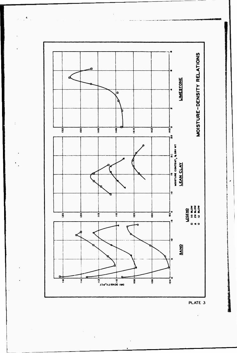
PLATE 3

Mflhmminwtwuir^MaK«
o
Ui a t-
i 2 D 2 P
u 5
Z Q. U O
>
V)
O o <
>- z fi
W 8 Ul O
<o
i Q
z
il < 2
58 a V
3
o
/
<" * —
/^ "^ X ^ k . a
tr-o-
O ( > < < ! ? 5 J 8
Wu
OS
12
o ■ u
h « a. •«
i y z Ss
o 5 J «i
' uO 2 z
* u" a > o <r •; S £ u t- a « _ §o { j t
3 I <»
o
< « o o
9 »- t- >- {: z u o ij u u < < 9 <t
311 I 0 0 4»
O
NI'HldJO
PLATE 4

=0=======—^J
r
CO >
>•
z 111 o > at
u z o (0 ui uo 3<
uu
o
5 2 s < 3 o z v> < <
a o 3
1 1
\ k :s>
^ v x o
\ -^
\
c L. 3 a <
in a
3^
x «n < >- 3 Z
a a * =
ii
in Ui 9 v a a
z? 23 i- «c u u
O o « i- k o
Ö , < ? •-9« a u o ui so I > o ,»- <
I» ^ " a O z K
isl, *•. " * 1- •>
£ fczS « i - oui <gOn.P
« « • o
M ̂ -^
■^
^ \.
— —
1 ^^
2 a 3F o p d (X UJ o a u. O
3 Si
>- g 5
N « • • e Nl'HXOa
PLATE 5

o fed r—
» » Ul
D V t- v w
Sy X Q A Vs. >i 5 • w v ■
vV X 2 VN >> D \ 2 \ ST
O \ v o c \ X \
>B b \ *- \ Ui
v % fl X K S,
X
Q.
O
5 > u H z
z < u
1 UJ o >- tr a
I/) u o < K U
s o !0
•> z 2 a 2 3 2 5
u z < < o w fe o o •
<-
UJ OC D t-
i 3 2 P
IS
u
- 2 u.
. ^ -v *-* ^ «5 <
in o *-0
O St SD
5 2« JS o ol wz 3 3? CS
*
I»)
i S5§§ •- K »- K
a t & o. ■ 3 o u u o u 11 O Q 4 »
PLATE 6

2 ? 3 3 o K <rt 0. v^ O Ui ii a o 3
»- K «1
O 2
Q Z < CO
a
i3
a o
Ml
• 5 - 9
!i -« S 1 u 3 * O 3
•IK < O
«3 z Mi «I
a z
Sf
a zo
z o>.
;c s
( s ? 2 o
£ o Ui If
o 1- >- M a 0 o s
a at •■ w i Ixi o
« a a ??? u a u
Hi
PLATE 7

2 3 ? S o (- I-: a. o w
tr O H M u O £ 2
>- t (0 z
>
UJ z g
^ a: u 8
u a
-' 5 * 2 " 2 :l o z £
a. o
2 7 3 ffw
2 o H o a o u
a u. 3 O t-
«1
or O a 2
SU
?! " OS ,.
si s Si i w -
>■ x
2? O OS" •) Z. " < oo z * SgpS
I < ft ji- 5 o -JU < O <1« I
<>■ *
■lO
« o
«i at
S° w a *- a. Z o >
if
u o o u * * * 5 & a 2 3 3 Ü o o O U <J o
S30*«3A03
PLATE 8

2 2
? o 6
1- N a. \-f
o Ul u o: n 3
H »- « Ul i
z a
iÜ o: u > o u
5
z < UJ J
hi ec 3
e ^ K - o «0
si H o Z £
2=» t- a. o
< > o u
oSffo " ^ 5 -
"So §5
'I I * «I * «!; w 3 u 5 5
|£§ SI «» s a?
0 2 # 3 0
m 1- v_/ a 0 UJ
K u. 3 O 1-
</) >- or O 0 2
& a 3 3 o o
O Cl Ü u
S10VH3A03
PLATE 9

VacAassifted SjcmjJjHJUjJjIkMjjJ^
OOCUMINT CONTIOL DATA • i A D (Stcmtir <lmfllltMtm< »< Hit», bolr »I «*«»i«cl «mi« Mtttmt m
t. OAlttlNATIN« ACTIVtTV
U. 3. Army Engineer Waterways Experiment Station Vickiburg, Mississippi
>. ««POUT TITLt
ÜÄ. . mtrany ucuairv Ck«Miric«TiOM Unclassified
SOIL COMPACTION INVESTIGATION; EVALL'ATION OF VIBRATOEY ROLLERS ON THREE TYPES OF SOILS
i. oc*em»Tiva Homcm» mittun Report 10 of a series
«nd Inchmlrm tmitt)
%. mtrtmmmjWKin Jim W. Hall
,mHm*MUmt, S«n
March 1968 M. COMTMACT OH
k. vaojccTHe.
7m. TOTAI. MO. OF *«•■*
32 »». MO. OF HBF«
0 M. emOINATOlCt ■■»OUT MUMMmSI
Technical Meaorandum No. 3-271, Report 10
M. OTMtM KCFORT HOI» «MKF MkW •
I*. DOTMOUTION tTATCMCNT
IHJIS document has been approved for public release and sale; its distribution Is unlimited.
II. (UFFLCHCMTAKV MOT» It. tFOHtOHIXa MILITAKT *CT>VITV
U. S. Air Force
II. «•1TI>*CT
'This study was conducted for the purpose of detenaining the ability of vibratory rollers to couroact soils. For coiaparative purposes, a 50-ton rubber-tired roller was used which is a required compaction device in present Corps of Engineers Guide Specifi- cations. Three vibratoit/ rollers were selected for study based on their operating frequency which encompassed the range over which present vibratory rollers operate. Results of this study show that light vibratory rollers can obtain satisfactory densities if lirt thicknesses are restricted. To evaluate the vibratory rollers, each was used to conpact three soil types (a lean clay, a crushed limestone, and a clean sand). Results indicate that a heavy, low-frequency vibratory roller will com- pact to greater depths than a light, high-frequency roller; however, the light, Mgh- frequency roller will corapact soil satisfactorily for a few inches below the surface. Soil types have a very definite influence on results obtained with vibratory rollers. The vibratory rollers generally perform better In granular soils; however, the heavy, low-frequency type rollers do a satisfactory job in clay soils, i
DD .'r..1473 ■■#«.*<«• •• FOdK l«»i. I tut M. OWCM I Unclassified
■MMrily CCSSHcaÜSä

Unclassified ktcmitf fctouincMtM
KIT «OMOl ■OL* "T ■OLI «T
Soils - -cOT^iactlon
Vibratory rollers
Uno LauJifled IccwItT CUMincatiM