evaluation report esr 3807
TRANSCRIPT

A Subsidiary of
0
000
Most Widely Accepted and Trusted
ICC‐ES Evaluation Report ESR‐3807Reissued 08/2017
This report is subject to renewal 08/2019.ICC‐ES | (800) 423‐6587 | (562) 699‐0543 | www.icc‐es.org
ICC-ES Evaluation Reports are not to be construed as representing aesthetics or any other attributes not specifically addressed, nor are they to be construed as an endorsement of the subject of the report or a recommendation for its use. There is no warranty by ICC Evaluation Service, LLC, express or implied, as to any finding or other matter in this report, or as to any product covered by the report.
Copyright © 2018 ICC Evaluation Service, LLC. All rights reserved.
“2014 Recipient of Prestigious Western States Seismic Policy Council (WSSPC) Award in Excellence”
DIVISION: 03 00 00—CONCRETE
SECTION: 03 16 00—CONCRETE ANCHORS
DIVISION: 05 00 00—METALS
SECTION: 05 05 19—POST‐INSTALLED CONCRETE ANCHORS
REPORT HOLDER:
TECNICAS EXPANSIVAS S.L.
C/SEGADOR 13 26006 LOGRONO (LA RIOJA)
SPAIN
EVALUATION SUBJECT:
INDEX MOPURE INJECTION SYSTEM ANCHORS FOR CRACKED AND UNCRACKED CONCRETE
Look for the trusted marks of Conformity!

ICC-ES Evaluation Reports are not to be construed as representing aesthetics or any other attributes not specifically addressed, nor are they to be construed as an endorsement of the subject of the report or a recommendation for its use. There is no warranty by ICC Evaluation Service, LLC, express or implied, as to any finding or other matter in this report, or as to any product covered by the report.
Copyright © 2018 ICC Evaluation Service, LLC. All rights reserved. Page 1 of 28
ICC-ES Evaluation Report ESR-3807 Reissued August 2017
Revised March 19, 2018
This report is subject to renewal August 2019.
www.icc-es.org | (800) 423-6587 | (562) 699-0543 A Subsidiary of the International Code Council ®
DIVISION: 03 00 00—CONCRETE Section: 03 16 00—Concrete Anchors DIVISION: 05 00 00—METALS Section: 05 05 19—Post-Installed Concrete Anchors REPORT HOLDER: TECNICAS EXPANSIVAS S.L. C/SEGADOR 13 26006 LOGRONO (LA RIOJA) SPAIN 34 941 272 131 www.indexfix.com [email protected] EVALUATION SUBJECT: INDEX MOPURE INJECTION SYSTEM ANCHORS FOR CRACKED AND UNCRACKED CONCRETE 1.0 EVALUATION SCOPE
Compliance with the following codes:
2015, 2012, 2009, 2006, and 2003 International Building Code® (IBC)
2015, 2012, 2009, 2006, and 2003 International Residential Code® (IRC)
Property evaluated:
Structural
2.0 USES
The Index MOPURE Injection System Anchors are used to resist static, wind or earthquake (Seismic Design Categories A through F) tension and shear loads in cracked and uncracked, normal-weight concrete having a specified compressive strength, f'c, of 2,500 psi to 8,500 psi (17.2 MPa to 58.6 MPa).
The anchors comply with anchors as described in Section 1901.3 of the 2015 IBC, Section 1909 of the 2012 IBC and are an alternative to cast-in-place anchors described in Section 1908 of the 2012 IBC, and Sections 1911 and 1912 of the 2009 and 2006 IBC, and Sections 1912 and 1913 of the 2003 IBC. The anchors may also be used where an engineered design is submitted in accordance with Section R301.1.3 of the IRC.
3.0 DESCRIPTION
3.1 General:
The Index MOPURE Injection System is comprised of the following:
Index MOPURE Injection System adhesive packaged in cartridges
Adhesive mixing and dispensing equipment
Equipment for cleaning holes and injecting adhesive
The Index MOPURE Injection System is used with continuously threaded steel rods or deformed steel reinforcing bars. Installation information, guidelines and parameters are shown in Tables 1, 15, 16, and 17 of this report.
The manufacturer’s printed installation instructions (MPII), included with each adhesive cartridge unit, are shown in Figure 3 of this report.
3.2 Materials:
3.2.1 Index MOPURE Injection System: The Index MOPURE Injection System is a two-component (resin and hardener) epoxy-based adhesive, supplied in dual chamber cartridges separating the chemical components, which are combined in a 1:1 ratio by volume when dispensed through the system static mixing nozzle. The Index MOPURE Injection System is available in 250 mL (9 fl. oz.), 400 mL (14 fl. oz.), 600 mL (21 fl. oz.) and 1500 mL (51 fl. oz.) cartridges. The shelf life of the Index MOPURE Injection System is two years, when stored in the manufacturer’s unopened containers at temperatures between 50°F (10 °C) and 77°F (25°C).
3.2.2 Dispensing Equipment: The Index MOPURE Injection System adhesive must be dispensed using pneumatic or manual actuated dispensing tools listed in Table 17 of this report.
3.2.3 Hole Preparation Equipment: The holes must be cleaned with hole-cleaning brushes and air nozzles. The brush must be the appropriate size brush shown in Tables 15 and 16 of this report and the air nozzle must be equipped with an extension capable of reaching the bottom of the drilled hole and having an inside bore diameter of not less than 1/4 inch (6 mm). The holes must be prepared in accordance with the installation instructions shown in Figure 3 of this report.

ESR-3807 | Most Widely Accepted and Trusted Page 2 of 28
3.2.4 Steel Anchor Elements:
3.2.4.1 Threaded Steel Rod: Threaded anchor rods must be clean, continuously threaded rods (all-thread) in diameters and types as described in Tables 2 and 4 of this report. Steel design information for the common grades of threaded rod is provided in Tables 2 and 4. Carbon steel threaded rods may be furnished with a zinc electroplated coating or hot-dipped galvanized, or may be uncoated. Threaded steel rods must be straight and free of indentations or other defects along their length.
3.2.4.2 Steel Reinforcing Bars: Steel reinforcing bars must be deformed bars (rebar). Tables 3 and 4 summarize reinforcing bar size ranges, specifications, and grades. The embedded portions of reinforcing bars must be straight, and free of mill scale, rust and other coatings or substances that may impair the bond with the adhesive. Reinforcing bars must not be bent after installation except as set forth in ACI 318-14 Section 26.6.3.1(b) or ACI 318-11 Section 7.3.2, as applicable, with the additional condition that the bars must be bent cold, and heating of reinforcing bars to facilitate field bending is not permitted.
3.2.4.3 Ductility: In accordance with ACI 318-14 2.3 or ACI 318-11 D.1, as applicable, in order for a steel element to be considered ductile, the tested elongation must be at least 14 percent and the reduction of area must be at least 30 percent. Steel elements with a tested elongation of less than 14 percent or a reduction of area less than 30 percent, or both, are considered brittle. Values for various steel materials are provided in Tables 2 through 4 of this report. Where values are nonconforming or unstated, the steel must be considered brittle.
3.3 Concrete:
Normal-weight concrete must comply with Sections 1903 and 1905 of the IBC, as applicable. The specified compressive strength of the concrete must be from 2,500 psi to 8,500 psi (17.2 MPa to 58.6 MPa).
4.0 DESIGN AND INSTALLATION
4.1 Strength Design:
4.1.1 General: The design strength of anchors under the 2015 IBC, as well as the 2015 IRC, must be determined in accordance with ACI 318-14 and this report. The design strength of anchors under the 2012, 2009, 2006 and 2003 IBC, as well as the 2012, 2009, 2006 and 2003 IRC, must be determined in accordance with ACI 318-11 and this report.
The strength design of anchors must comply with ACI 318-14 17.3.1 or ACI 318-11 D.4.1, as applicable, except as required in ACI 318-14 17.2.3 or ACI 318-11 D.3.3, as applicable.
A design example in accordance with the 2012 IBC is given in Figure 4 of this report.
Design parameters are provided in Tables 2 through 10 of this report. Strength reduction factors, , as described in ACI 318-14 17.3.3 or ACI 318-11 D.4.3, as applicable, must be used for load combinations calculated in accordance with Section 1605.2 of the IBC or ACI 318-14 5.3 or ACI 318-11 9.2, as applicable. Strength reduction factors, , described in ACI 318-11 D.4.4 must be used for load combinations calculated in accordance with Appendix C of ACI 318-11.
4.1.2 Static Steel Strength in Tension: The nominal static steel strength of a single anchor in tension, Nsa, in accordance with ACI 318-14 17.4.1.2 or ACI 318-11 D.5.1.2, as applicable, and the associated strength reduction factor, , in accordance with ACI 318-14 17.3.3 or ACI 318-11 D.4.3, as applicable, are provided in Tables
2, 3, and 4 for the anchor element types included in this report.
4.1.3 Static Concrete Breakout Strength in Tension: The nominal static concrete breakout strength of a single anchor or group of anchors in tension, Ncb or Ncbg, must be calculated in accordance with ACI 318-14 17.4.2 or ACI 318-11 D.5.2, as applicable, with the following addition:
The basic concrete breakout strength of a single anchor in tension, Nb, must be calculated in accordance with ACI 318-14 17.4.2.2 or ACI 318-11 D.5.2.2, as applicable, using the selected values of kc,cr and kc,uncr as provided in the tables of this report. Where analysis indicates no cracking in accordance with ACI 318-14 17.4.2.6 or ACI 318-11 D.5.2.6, as applicable, Nb must be calculated using kc,uncr and Ψc,N = 1.0. For anchors in lightweight concrete see ACI 318-14 17.2.6 or ACI 318-11 D.3.6, as applicable. The value of f′c used for calculation must be limited to 8,000 psi (55 MPa) in accordance with ACI 318-14 17.2.7 or ACI 318-11 D.3.7, as applicable. Additional information for the determination of nominal bond strength in tension is given in Section 4.1.4 of this report.
4.1.4 Static Bond Strength in Tension: The nominal static bond strength of a single adhesive anchor or group of adhesive anchors in tension, Na or Nag, must be calculated in accordance with ACI 318-14 17.4.5 or ACI 318-11 D.5.5, as applicable. Bond strength values are a function of the concrete condition, whether the concrete is cracked or uncracked, the concrete temperature range, and the installation conditions (dry or water-saturated concrete, water-filled holes). The resulting characteristic bond strength shall be multiplied by the associated strength reduction factor nn as follows corresponding to the level of special inspection provided:
CONCRETESTATE
DRILLING METHOD
PERMISSIBLE INSTALLATION CONDITIONS
BOND STRESS
ASSOCIATEDSTRENGTH REDUCTION
FACTOR
Cracked Hammer-
drill
Dry concrete k,cr d
Water-saturated concrete k,cr ws
Water-filled hole (flooded) k,cr wf
UncrackedHammer-
drill
Dry concrete k,uncr d
Water-saturated concrete k,uncr ws
Water-filled hole (flooded) k,uncr wf
Figure 1 of this report presents a bond strength design selection flowchart. Strength reduction factors for determination of the bond strength are given in Tables 7 through 14 of this report.
4.1.5 Static Steel Strength in Shear: The nominal static strength of a single anchor in shear as governed by the steel, Vsa, in accordance with ACI 318-14 17.5.1.2 or ACI 318-11 D.6.1.2, as applicable, and strength reduction factors, , in accordance with ACI 318-14 17.3.3 or ACI 318-11 D.4.3, as applicable, are given in Tables 2 through 4 of this report for the anchor element types included in this report.
4.1.6 Static Concrete Breakout Strength in Shear: The nominal concrete breakout strength of a single anchor or group of anchors in shear, Vcb or Vcbg, must be calculated in accordance with ACI 318-14 17.5.2 or ACI 318-11 D.6.2, as applicable, based on information given in Tables 5 and 6 of this report. The basic concrete breakout strength of a single anchor in shear, Vb, must be calculated in accordance with ACI 318-14 17.5.2.2 or ACI 318-11

ESR-3807 | Most Widely Accepted and Trusted Page 3 of 28
D.6.2.2, as applicable, using the values of d given in Tables 2 through 4 for the corresponding anchor steel in lieu of da (2015, 2012 and 2009 IBC) and do (IBC 2006). In addition, hef must be substituted for ℓe. In no case shall ℓe exceed 8d. The value of f′c must be limited to a maximum of 8,000 psi (55 MPa), in accordance with ACI 318-14 17.2.7 or ACI 318-11 D.3.7, as applicable.
4.1.7 Static Concrete Pryout Strength in Shear: The nominal static pryout strength of a single anchor or group of anchors in shear, Vcp or Vcpg, shall be calculated in accordance with ACI 318-14 17.5.3 or ACI 318-11 D.6.3, as applicable.
4.1.8 Interaction of Tensile and Shear Forces: For designs that include combined tension and shear forces, the interaction of the tension and shear loads must be calculated in accordance with ACI 318-14 17.6 or ACI 318-11 D.7, as applicable.
4.1.9 Minimum Member Thickness, hmin, Anchor Spacing, smin, and Minimum Edge Distance, cmin: In lieu of ACI 318-14 17.7.1 and 17.7.3 or ACI 318-11 D.8.1 and D.8.3, as applicable, values of smin and cmin described in this report must be observed for anchor design and installation. The minimum member thickness, hmin, described in this report must be observed for anchor design and installation. For adhesive anchors that will remain untorqued, ACI 318-14 17.7.4 or ACI 318-11 D.8.4, as applicable, applies.
4.1.10 Critical Edge Distance cac and ψcp,Na: The modification factor ψcp,Na, must be determined in accordance with ACI 318-14 17.4.5.5 or ACI 318-11 D.5.5.5, as applicable, except as noted below:
For all cases where cNa/cac<1.0, ψcp,Na determined from ACI 318-14 Eq. 17.4.5.5b or ACI 318-11 Eq. D-27, as applicable, need not be taken less than cNa/cac. For all other cases, ψcp,Na shall be taken as 1.0.
The critical edge distance, cac must be calculated according to Eq. 17.4.5.5c for ACI 318-14 or Eq. D-27a for ACI 318-11, in lieu of ACI 318-14 17.7.6 or ACI 318-11 D.8.6, as applicable.
∙ ,.∙ 3.1 0.7
(Eq. 17.4.5.5c for ACI 318-14 or Eq. D-27a for ACI 318-11) where
need not be taken as larger than 2.4; and
k,uncr = the characteristic bond strength stated in the tables of this report whereby k,uncr need not be taken as larger than:
, ∙ Eq. (4-1)
4.1.11 Design Strength in Seismic Design Categories C, D, E and F: In structures assigned to Seismic Design Category C, D, E or F under the IBC or IRC, anchors must be designed in accordance with ACI 318-14 17.2.3 or ACI 318-11 D.3.3, as applicable, except as described below.
The nominal steel shear strength, Vsa, must be adjusted by V,seis as given in Tables 2 through 4 of this report for the corresponding anchor steel.
As an exception to ACI 318-11 D.3.3.4.2: Anchors designed to resist wall out-of-plane forces with design strengths equal to or greater than the force determined in accordance with ASCE 7 Equation 12.11-1 or 12.14-10 shall be deemed to satisfy ACI 318-11 D.3.3.4.3(d).
Under ACI 318-11 D.3.3.4.3(d), in lieu of requiring the anchor design tensile strength to satisfy the tensile strength requirements of ACI 318-11 D.4.1.1, the anchor design tensile strength shall be calculated from ACI 318-11 D.3.3.4.4.
The following exceptions apply to ACI 318-11 D.3.3.5.2:
1. For the calculation of the in-plane shear strength of anchor bolts attaching wood sill plates of bearing or non-bearing walls of light-frame wood structures to foundations or foundation stem walls, the in-plane shear strength in accordance with ACI 318-11 D.6.2 and D.6.3 need not be computed and ACI 318-11 D.3.3.5.3 need not apply provided all of the following are satisfied:
1.1. The allowable in-plane shear strength of the anchor is determined in accordance with AF&PA NDS Table 11E for lateral design values parallel to grain.
1.2. The maximum anchor nominal diameter is 5/8 inch (16 mm).
1.3. Anchor bolts are embedded into concrete a minimum of 7 inches (178 mm).
1.4. Anchor bolts are located a minimum of 13/4 inches (45 mm) from the edge of the concrete parallel to the length of the wood sill plate.
1.5. Anchor bolts are located a minimum of 15 anchor diameters from the edge of the concrete perpendicular to the length of the wood sill plate.
1.6. The sill plate is 2-inch or 3-inch nominal thickness.
2. For the calculation of the in-plane shear strength of anchor bolts attaching cold-formed steel track of bearing or non-bearing walls of light-frame construction to foundations or foundation stem walls, the in-plane shear strength in accordance with ACI 318-11 D.6.2 and D.6.3 need not be computed and ACI 318-11 D.3.3.5.3 need not apply provided all of the following are satisfied:
2.1. The maximum anchor nominal diameter is 5/8 inch (16 mm).
2.2. Anchors are embedded into concrete a minimum of 7 inches (178 mm).
2.3. Anchors are located a minimum of 13/4 inches (45 mm) from the edge of the concrete parallel to the length of the track.
2.4. Anchors are located a minimum of 15 anchor diameters from the edge of the concrete perpendicular to the length of the track.
2.5. The track is 33 to 68 mil designation thickness.
Allowable in-plane shear strength of exempt anchors, parallel to the edge of concrete shall be permitted to be determined in accordance with AISI S100 Section E3.3.1.
3. In light-frame construction, bearing or nonbearing walls, shear strength of concrete anchors less than or equal to 1 inch [25 mm] in diameter attaching a sill plate or track to foundation or foundation stem wall need not satisfy ACI 318-11 D.3.3.5.3(a) through (c) when the design strength of the anchors is determined in accordance with ACI 318-11 D.6.2.1(c).
4.2 Allowable Stress Design (ASD):
4.2.1 General: For anchors designed using load combinations calculated in accordance with IBC Section 1605.3 (Allowable Stress Design), allowable loads must be established using the following relationships:

ESR-3807 | Most Widely Accepted and Trusted Page 4 of 28
Tallowable,ASD = Nn/α Eq. (4-2)
Vallowable,ASD = Vn/α Eq. (4-3)
where
Tallowable,ASD = Allowable tension load (lbf or kN)
Vallowable,ASD = Allowable shear load (lbf or kN)
Nn = The lowest design strength of an anchor or anchor group in tension as determined in accordance with ACI 318-14 Chapter 17 and 2015 IBC Section 1905.1.8; ACI 318-11 Appendix D as amended in this report; ACI 318-08 Appendix D and 2009 IBC Sections 1908.1.9 and 1908.1.10; or ACI 318-05 Appendix D and 2006 IBC Section 1908.1.16, as applicable.
Vn = The lowest design strength of an anchor or anchor group in shear as determined in accordance with ACI 318-14 Chapter 17 and 2015 IBC Section 1905.1.8; ACI 318-11 Appendix D as amended in this report; ACI 318-08 Appendix D and 2009 IBC Sections 1908.1.9 and 1908.1.10; or ACI 318-05 Appendix D and 2006 IBC Section 1908.1.16, as applicable.
= Conversion factor calculated as a weighted average of the load factors for the controlling load combination. In addition, must include all applicable factors to account for non-ductile failure modes and required over-strength.
Table 19 provides an illustration of calculated Allowable Stress Design (ASD) values for each anchor diameter at minimum embedment depth.
The requirements for member thickness, edge distance and spacing, as described in Table 1 of this report, must apply. An example of allowable stress design values for illustrative purposes is shown in Figure 4 of this report.
4.2.2 Interaction of Tensile and Shear Forces: In lieu of ACI 318-14 17.6.1, 17.6.2, and 17.6.3 or ACI 318-11 D.7.1, D.7.2 and D.7.3, as applicable, interaction of tension and shear loads must be calculated as follows:
For tension loads T ≤ 0.2 · Tallowable,ASD, the full allowable strength in shear, Vallowable,ASD, shall be permitted.
For shear loads V ≤ 0.2 · Vallowable,ASD, the full allowable strength in tension, Tallowable,ASD, shall be permitted.
For all other cases:
T
Tallowable,ASD+
V
Vallowable,ASD≤1.2 Eq. (4-4)
4.3 Installation:
Installation parameters are provided in Tables 1, 15, 16, 17, and Figure 3. Installation must be in accordance with ACI 318-14 17.8.1 and 17.8.2 or ACI 318-11 D.9.1 and D.9.2, as applicable. Anchor locations must comply with this report and the plans and specifications approved by the building official. Installation of the Index MOPURE Injection System adhesive anchor system must conform to the manufacturer’s printed installation instructions (MPII) included in each package unit and as described in Figure 3. The nozzles, brushes, dispensing tools and resin stoppers shown in Figure 2 and listed in Tables 15, 16, and 17 supplied by the manufacturer, must be used along with the adhesive cartridges. Installation of anchors may be vertically down (floor), horizontal (walls) and vertically overhead. Use of nozzle extension tubes and resin stoppers must be in accordance with Tables 15 and 16.
4.4 Special Inspection:
4.4.1 General: Installations may be made under continuous special inspection or periodic special
inspection, as determined by the registered design professional. Tables 7 through 14 of this report provide strength reduction factors, , corresponding to the type of inspection provided.
Continuous special inspection of adhesive anchors installed in horizontal or upwardly inclined orientations to resist sustained tension loads shall be performed in accordance with ACI 318-14 17.8.2.4 or ACI 318-11 D.9.2.4, as applicable.
Under the IBC, additional requirements as set forth in Sections 1705, 1706 or 1707 must be observed, where applicable.
4.4.2 Continuous Special Inspection: Installations made under continuous special inspection with an on-site proof loading program must be performed in accordance with Section 1705.1.1 and Table 1705.3 of the 2015 and 2012 IBC, Section 1704.15 and Table 1704.4 of the 2009 IBC, or Section 1704.13 of the 2006 or 2003 IBC, whereby continuous special inspection is defined in Section 1702.1 of the IBC, and this report. The special inspector must be on the jobsite continuously during anchor installation to verify anchor type, adhesive expiration date, anchor dimensions, concrete type, concrete compressive strength, hole dimensions, hole cleaning procedures, anchor spacing, edge distances, concrete thickness, anchor embedment, tightening torque, and adherence to the manufacturer’s printed installation instructions.
The proof loading program must be established by the registered design professional. As a minimum, the following requirements must be addressed in the proof loading program:
1. Frequency of proof loading based on anchor type, diameter, and embedment.
2. Proof loads by anchor type, diameter, embedment, and location.
3. Acceptable displacements at proof load.
4. Remedial action in the event of a failure to achieve proof load, or excessive displacement.
Unless otherwise directed by the registered design professional, proof loads must be applied as confined tension tests. Proof load levels must not exceed the lesser of 67 percent of the load corresponding to the nominal bond strength as calculated from the characteristic bond stress for uncracked concrete modified for edge effects and concrete properties, or 80 percent of the minimum specified anchor element yield strength (Ase,N fya). The proof load shall be maintained at the required load level for a minimum of 10 seconds.
4.4.3 Periodic Special Inspection: Periodic special inspection must be performed where required in accordance with Section 1705.1.1 and Table 1705.3 of the 2015 and 2012 IBC, Sections 1704.4 and 1704.15 of the 2009 IBC or Section 1704.13 of the 2006 or 2003 IBC and this report. The special inspector must be on the jobsite initially during anchor installation to verify the anchor type, anchor dimensions, concrete type, concrete compressive strength, adhesive identification and expiration date, hole dimensions, hole cleaning procedures, anchor spacing, edge distances, concrete thickness, anchor embedment, tightening torque and adherence to the manufacturer’s published installation instructions. The special inspector must verify the initial installations of each type and size of adhesive anchor by construction personnel on site. Subsequent installations of the same anchor type and size by the same construction personnel are permitted to be performed in the absence of the special inspector. Any
ESR-3807 | Most Widely Accepted and Trusted Page 5 of 28
change in the anchor product being installed or the personnel performing the installation requires an initial inspection. For ongoing installations over an extended period, the special inspector must make regular inspections to confirm correct handling and installation of the product.
5.0 CONDITIONS OF USE
The Index MOPURE Injection System adhesive anchor system described in this report complies with or is a suitable alternative to what is specified in the codes listed in Section 1.0 of this report, subject to the following conditions:
5.1 Index MOPURE Injection System adhesive anchors must be installed in accordance with the manufacturer’s printed installation instructions (MPII) and as shown in Figure 3 of this report.
5.2 The anchors must be installed in cracked or uncracked normal-weight concrete having a specified compressive strength, f'c = 2,500 psi to 8,500 psi (17.2 MPa to 58.6 MPa).
5.3 The values of f'c used for calculation purposes must not exceed 8,000 psi (55.1 MPa).
5.4 Anchors must be installed in concrete base materials in holes predrilled in accordance with the instructions provided in Figure 3 of this report, with carbide-tipped drill bits complying with ANSI B212.15-1994.
5.5 Loads applied to the anchors must be adjusted in accordance with Section 1605.2 of the IBC for strength design, and Section 1605.3 of the IBC for allowable stress design.
5.6 Index MOPURE Injection System adhesive anchors are recognized for use to resist short- and long-term loads, including wind and earthquake, subject to the conditions of this report.
5.7 In structures assigned to Seismic Design Category C, D, E or F under the IBC or IRC, anchor strength must be adjusted in accordance with Section 4.1.11 of this report.
5.8 Index MOPURE Injection System adhesive anchors are permitted to be installed in concrete that is cracked or that may be expected to crack during the service life of the anchor, subject to the conditions of this report.
5.9 Strength design values must be established in accordance with Section 4.1 of this report.
5.10 Allowable stress design values must be established in accordance with Section 4.2 of this report.
5.11 Minimum anchor spacing and edge distance, as well as minimum member thickness, must comply with the values described in this report.
5.12 Prior to installation, calculations and details demonstrating compliance with this report must be submitted to the code official. The calculations and details must be prepared by a registered design professional where required by the statutes of the jurisdiction in which the project is to be constructed.
5.13 Anchors are not permitted to support fire-resistive construction. Where not otherwise prohibited by the code, Index MOPURE Injection System anchors are permitted for installation in fire-resistive construction provided at least one of the following conditions is fulfilled:
Anchors are used to resist wind or seismic forces only.
Anchors that support gravity load-bearing structural elements are within a fire-resistive envelope or a fire-resistive membrane, are protected by approved fire-resistive materials, or have been evaluated for resistance to fire exposure in accordance with recognized standards.
Anchors are used to support nonstructural elements.
5.14 Since an ICC-ES acceptance criteria for evaluating data to determine the performance of adhesive anchors subjected to fatigue or shock loading is unavailable at this time, the use of these anchors under such conditions is beyond the scope of this report.
5.15 Use of zinc-plated carbon steel threaded rods or steel reinforcing bars is limited to dry, interior locations.
5.16 Use of hot-dipped galvanized carbon steel and stainless steel rods is permitted for exterior exposure or damp environments.
5.17 Steel anchoring materials in contact with preservative-treated wood and fire-retardant-treated wood must be zinc-coated carbon steel or stainless steel. The minimum coating weights for zinc-coated steel must comply with ASTM A153.
5.18 Special inspection must be provided in accordance with Section 4.4 in this report. Continuous special inspection for anchors installed in horizontal or upwardly inclined orientations to resist sustained tension loads must be provided in accordance with Section 4.4 of this report.
5.19 Installation of anchors in horizontal or upwardly inclined orientations to resist sustained tension loads shall be performed by personnel certified by an applicable certification program in accordance with ACI 318-14 17.8.2.2 or 17.8.2.3 or ACI 318-11 D.9.2.2 or D.9.2.3, as applicable.
5.20 Index MOPURE Injection System adhesive anchors may be used to resist tension and shear forces in floor, wall, and overhead installations only if installation is into concrete with a temperature between 40°F and 104°F (4°C and 40°C) for threaded rods and rebar. Overhead installations for hole diameters larger than 5/8-inch or 16 mm require the use of resin stoppers during injection to the back of the hole. ½-inch, 9/16-inch, 5/8-inch, 12 mm, 14 mm, and 16 mm diameter holes may be injected directly to the back of the hole with the use of extension tubing on the end of the nozzle, The anchor must be supported until fully cured (i.e., with wedges, or other suitable means). Where temporary restraint devices are used, their use shall not result in impairment of the anchor shear resistance.
5.21 Anchors shall not be used for installations where the concrete temperature can rise from 40°F (or less) to 80°F (or higher) within a 12-hour period. Such applications may include but are not limited to anchorage of building facade systems and other applications subject to direct sun exposure.
5.22 Index MOPURE Injection System is manufactured and packaged into cartridges in Alfreton, United Kingdom, under a quality control program with inspections by ICC-ES.

ESR-3807 | Most Widely Accepted and Trusted Page 6 of 28 6.0 EVIDENCE SUBMITTED
Data in accordance with the ICC-ES Acceptance Criteria for Post-installed Adhesive Anchors in Concrete (AC308), dated October 2017, which incorporates requirements in ACI 355.4-11.
7.0 IDENTIFICATION
7.1 Index MOPURE Injection System is identified in the field by labels on the cartridge and packaging, bearing the company name (Tecnicas Expansivas S.L.), product name (Index MOPURE Injection System), the
batch number, the expiration date, and the evaluation report number (ESR-3807).
7.2 Threaded rods, nuts, and washers are standard elements, and must conform to applicable national or international specifications.

ESR-3807 | Most Widely Accepted and Trusted Page 7 of 28
TABLE 1—INDEX MOPURE INJECTION SYSTEM ANCHOR SYSTEM INSTALLATION INFORMATION
Characteristic Symbol Units Nominal Anchor Element Diameter
Fractional Threaded Rod
Size do inch 3/8 1/2 5/8 3/4 7/8 1 11/4
Drill Size dhole inch 1/2 9/16 3/4 7/8 1 11/8 13/8
Fractional Re-bar Size do inch #3 #4 #5 #6 #7 #8 #10
Drill Size dhole inch 9/16 5/8 3/4 7/8 1 11/8 13/8
Metric Threaded Rod
Size do mm M10 M12 M16 M20 - M24 M30
Drill Size dhole mm 12 14 18 22 - 26 35
Metric Re-bar Size do mm T10 T12 T16 T20 - T25 T32
Drill Size dhole mm 14 16 20 25 - 32 40
Maximum Tightening Torque Tinst ft·lb 15 30 60 100 125 150 200
Embedment Depth Range hef,min inch 23/8 23/4 31/8 33/4 4 4 5
hef,max inch 71/2 10 121/2 15 171/2 20 25
Minimum Concrete Thickness hmin inch 1.5 · hef
Critical Edge Distance cac inch See Section 4.1.10 of this report
Minimum Edge Distance cmin inch 11/2 11/2 13/4 17/8 2 2 21/2
Minimum Anchor Spacing smin inch 11/2 11/2 13/4 17/8 2 2 21/2
For SI: 1 inch = 25.4 mm, 1 ft·lb = 1.356 N·m
FIGURE 1—FLOWCHART FOR THE ESTABLISHMENT OF DESIGN BOND STRENGTH

ESR-3807 | Most Widely Accepted and Trusted Page 8 of 28
TABLE 2—STEEL DESIGN INFORMATION FOR FRACTIONAL CARBON STEEL AND STAINLESS STEEL THREADED ROD1,2
Characteristic Symbol Units Nominal Rod Diameter, do
Nominal Size do inch 3/8 1/2
5/8 3/4
7/8 1 11/4
Stress Area1 Ase in.2 0.0775 0.1419 0.226 0.334 0.462 0.606 0.969
Car
bon
Ste
el T
hrea
ded
Rod
Strength Reduction Factor for Tension Steel Failure2 - 0.75
Strength Reduction Factor for Shear Steel Failure2 - 0.65
Reduction for Seismic Tension N,seis - 1.00
Reduction for Seismic Shear V,seis - 0.58 0.57 0.57 0.57 0.42 0.42 0.42
Tension Resistance of Carbon Steel Nsa
lb 4,495 8,230 13,110 19,370 26,795 35,150 56,200
ASTM F1554 Grade 36 (kN) (20.0) (36.6) (58.3) (86.2) (119.2) (156.4) (250.0)
Tension Resistance of Carbon Steel Nsa
lb 9,690 17,740 28,250 41,750 57,750 75,750 121,125
ASTM A193 B7 (kN) (43.1) (78.9) (125.7) (185.7) (256.9) (337.0) (538.8)
Shear Resistance of Carbon Steel Vsa
lb 2,250 4,940 7,865 11,625 16,080 21,090 33,720
ASTM F1554 Grade 36 (kN) (10.0) (22.0) (35.0) (51.7) (71.5) (93.8) (150.0)
Shear Resistance of Carbon Steel Vsa
lb 4,845 10,645 16,950 25,050 34,650 45,450 72,675
ASTM A193 B7 (kN) (21.6) (47.4) (75.4) (111.4) (154.1) (202.2) (323.3)
Sta
inle
ss S
teel
Thr
eade
d R
od
Strength Reduction Factor for Tension Steel Failure2 - 0.65
Strength Reduction Factor for Shear Steel Failure2 - 0.60
Reduction for Seismic Tension N,seis - 1.00
Reduction for Seismic Shear V,seis - 0.51 0.50 0.49 049 0.43 0.43 0.43
Tension Resistance of Stainless Steel Nsa
lb 7,365 13,480 21,470 -- -- -- --
ASTM F593 CW1 (kN) (32.8) (60.0) (95.5)
Tension Resistance of Stainless Steel Nsa
lb -- -- -- 25,385 35,110 46,055 73,645
ASTM F593 CW2 (kN) (112.9) (156.2) (204.9) (327.6)
Tension Resistance of Stainless Steel Nsa
lb 8,915 16,320 25,990 -- -- -- --
ASTM F593 SH1 (kN) (39.7) (72.6) (115.6)
Tension Resistance of Stainless Steel Nsa
lb -- -- -- 35,070 48,510 63,630 --
ASTM F593 SH2 (kN) (156.0) (215.8) (283.0)
Tension Resistance of Stainless Steel Nsa
lb -- -- -- -- -- -- 92,055
ASTM F593 SH3 (kN) (409.5)
Shear Resistance of Stainless Steel Vsa
lb 3,680 6,740 10,735 -- -- -- --
ASTM F593 CW1 (kN) (16.4) (30.0) (47.8)
Shear Resistance of Stainless Steel Vsa
lb -- -- -- 12,690 17,555 23,030 36,820
ASTM F593 CW2 (kN) (56.4) (78.1) (102.4) (163.8)
Shear Resistance of Stainless Steel Vsa
lb 4,455 9,790 15,595 -- -- -- --
ASTM F593 SH1 (kN) (19.8) (43.5) (69.4)
Shear Resistance of Stainless Steel Vsa
lb -- -- -- 17,535 24,255 31,815 --
ASTM F593 SH2 (kN) (78.0) (107.9) (141.5)
Shear Resistance of Stainless Steel Vsa
lb -- -- -- -- -- -- 46,030
ASTM F593 SH3 (kN) (204.8)
For SI: 1 inch = 25.4 mm, 1 in.2 = 645.16 mm2, 1 lb = 0.004448 kN
1Values provided for steel threaded rod are based on minimum specified strengths and calculated in accordance with ACI 318-14 Eq. 17.4.1.2 and Eq. 17.5.1.2b or ACI 318-11 Eq. (D-2) and Eq. (D-29), as applicable. 2The tabulated value of applies when the load combinations of Section 1605.2 of the IBC, ACI 318-14 5.3, or ACI 318-11 Section 9.2, as applicable, are used in accordance with ACI 318-14 17.3.3 or ACI 318-11 D.4.3, as applicable. If the load combinations of ACI 318-11 Appendix C are used, the appropriate value of must be determined in accordance with ACI 318-11 D.4.4.

ESR-3807 | Most Widely Accepted and Trusted Page 9 of 28
TABLE 3—STEEL DESIGN INFORMATION FOR FRACTIONAL STEEL REINFORCING BAR1,2
Characteristic Symbol Units Nominal Reinforcing Bar size, do
No. 3 No. 4 No. 5 No. 6 No. 7 No. 8 No. 10
Rei
nfor
cing
bar
Nominal bar diameter do inch 0.375 0.500 0.625 0.750 0.875 1.000 1.250
Stress Area Ase in.2 0.11 0.20 0.31 0.44 0.60 0.79 1.27
Strength Reduction Factor for Tension Steel Failure - 0.65
Strength Reduction Factor for Shear Steel Failure - 0.60
Reduction for Seismic Tension N,seis - 1.00
Reduction for Seismic Shear V,seis - 0.70 0.70 0.82 0.82 0.42 0.42 0.42
Tension Resistance of Carbon Steel Nsa
lb 6,600 12,000 18,600 26,400 36,000 47,400 76,200
ASTM A615 Grade 40 (kN) (29.4) (53.4) (82.7) (117.4) (160.1) (210.8) (339.0)
Tension Resistance of Carbon Steel Nsa
lb 9,900 18,000 27,900 39,600 54,000 71,100 114,300
ASTM A615 Grade 60 (kN) (44.0) (80.1) (124.1) (176.1) (240.2) (316.3) (508.4)
Shear Resistance of Carbon Steel Vsa
lb 3,960 7,200 11,160 15,840 21,600 28,440 45,720
ASTM A615 Grade 40 (kN) (17.6) (32.0) (49.6) (70.5) (96.1) (126.5) (203.4)
Shear Resistance of Carbon Steel Vsa
lb 5,940 10,800 16,740 23,760 32,400 42,660 68,580
ASTM A615 Grade 60 (kN) (26.4) (48.0) (74.5) (105.7) (144.1) (189.8) (305.1)
For SI: 1 inch = 25.4 mm, 1 in.2 = 645.16 mm2, 1 lb = 0.004448 kN
1Values provided for steel threaded rod are based on minimum specified strengths and calculated in accordance with ACI 318-14 Eq. 17.4.1.2 and Eq. 17.5.1.2b or ACI 318-11 Eq. (D-2) and Eq. (D-29), as applicable. 2The tabulated value of applies when the load combinations of Section 1605.2 of the IBC, ACI 318-14 5.3, or ACI 318-11 Section 9.2 are used in accordance with ACI 318-14 17.3.3 or ACI 318-11 D.4.3, as applicable. If the load combinations of ACI 318-11 Appendix C are used, the appropriate value of must be determined in accordance with ACI 318-11 D.4.4.

ESR-3807 | Most Widely Accepted and Trusted Page 10 of 28
TABLE 4—STEEL DESIGN INFORMATION FOR METRIC THREADED ROD AND REINFORCING BAR1,2
Characteristic Symbol Units Nominal Rod Diameter, do M
etri
c T
hre
ade
d R
od
Nominal Size do mm M10 M12 M16 M20 M24 M30
Stress Area Ase mm2 58 84 157 245 353 561
Strength Reduction Factor for Tension Steel Failure - 0.65
Strength Reduction Factor for Shear Steel Failure - 0.60
Reduction for Seismic Tension N,seis - 1.00
Reduction for Seismic Shear V,seis - 0.58 0.57 0.57 0.42 0.42 0.42
Tension Resistance of Carbon Steel Nsa
kN 29.0 42.2 78.5 122.5 176.5 280.5 ISO 898-1 Class 5.8 lb (6,519) (9,476) (17,648) (27,539) (39,679) (63,059)
Tension Resistance of Carbon Steel Nsa
kN 46.4 67.4 125.6 196.0 282.4 448.8 ISO 898-1 Class 8.8 lb (10,431) (15,161) (28,236) (44,063) (63,486) (100,894)
Tension Resistance of Carbon Steel Nsa
kN 50.0 72.7 135.3 211.2 304.3 483.6 ISO 898-1 Class 12.9 lb (11,240) (16,336) (30,424) (47,477) (68,406) (108,714)
Tension Resistance of Stainless Steel Nsa
kN 40.6 59.0 109.9 171.5 247.1 392.7 ISO 3506-1 A4-70 lb (9,127) (13,266) (24,707) (38,555) (55,550) (88,282)
Tension Resistance of Stainless Steel Nsa
kN 46.4 67.4 125.6 196.0 282.4 448.8 ISO 3506-1 A4-80 lb (10,431) (15,161) (28,236) (44,063) (63,486) (100,894)
Shear Resistance of Carbon Steel Vsa
kN 17.4 25.3 47.1 73.5 105.9 168.3 ISO 898-1 Class 5.8 lb (3,912) (5,685) (10,589) (16,523) (23,807) (37,835)
Shear Resistance of Carbon Steel Vsa
kN 27.8 40.5 75.4 117.6 169.4 269.3 ISO 898-1 Class 8.8 lb (6,259) (9,097) (16,942) (26,438) (38,092) (60,537)
Shear Resistance of Carbon Steel Vsa
kN 30.0 43.6 81.2 126.7 182.6 290.1 ISO 898-1 Class 12.9 lb (6,744) (9,802) (18,255) (28,486) (41,044) (65,228)
Shear Resistance of Stainless Steel Vsa
kN 24.4 35.4 65.9 102.9 148.3 235.6 ISO 3506-1 A4-70 lb (5,476) (7,960) (14,824) (23,133) (33,330) (52,969)
Shear Resistance of Stainless Steel Vsa
kN 27.8 40.5 75.4 117.6 169.4 269.3 ISO 3506-1 A4-80 lb (6,259) (9,097) (16,942) (26,438) (38,092) (60,537)
Met
ric
Rei
nfo
rcin
g b
ar
Nominal Size do mm T10 T12 T16 T20 T25 T32
Stress Area Ase mm2 78.5 113 201 314 491 804
Strength Reduction Factor for Tension Steel Failure - 0.65
Strength Reduction Factor for Shear Steel Failure - 0.60
Reduction for Seismic Tension N,seis - 1.00
Reduction for Seismic Shear V,seis - 0.70 0.70 0.82 0.42 0.42 0.42
Tension Resistance of DIN 488 BSt 500 Nsa
kN 43.2 62.2 110.6 172.7 270.1 442.2 lb (9,706) (13,972) (24,853) (38,825) (60,710) (99,411)
Shear Resistance of DIN 488 BSt 500 Vsa
kN 25.9 37.3 66.3 103.6 162.0 265.3 lb (5,824) (8,383) (14,912) (23,295) (36,426) (59,646)
For SI: 1 inch = 25.4 mm, 1 in.2 = 645.16 mm2, 1 lb = 0.004448 kN 1Values provided for steel threaded rod are based on minimum specified strengths and calculated in accordance with ACI 318-14 Eq. 17.4.1.2 and Eq. 17.5.1.2b or ACI 318-11 Eq. (D-2) and Eq. (D-29), as applicable. 2The tabulated value of applies when the load combinations of Section 1605.2 of the IBC, ACI 318-14 5.3, or ACI 318-11 Section 9.2 are used in accordance with ACI 318-14 17.3.3 or ACI 318-11 D.4.3, as applicable. If the load combinations of ACI 318-11 Appendix C are used, the appropriate value of must be determined in accordance with ACI 318-11 D.4.4.

ESR-3807 | Most Widely Accepted and Trusted Page 11 of 28
TABLE 5—FRACTIONAL THREADED ROD AND REINFORCING BAR CONCRETE BREAKOUT STRENGTH DESIGN INFORMATION
Characteristic Symbol Units Nominal Anchor Element Diameter
US Threaded
Rod
Size do Inch 3/8 1/2 5/8 3/4 7/8 1 11/4
Drill Size dhole Inch 1/2 9/16 3/4 7/8 1 11/8 13/8
US Re-bar Size do Inch No. 3 No. 4 No. 5 No. 6 No. 7 No. 8 No. 10
Drill Size dhole Inch 9/16 5/8 3/4 7/8 1 11/8 13/8
Embedment Depth Range hef,min Inch 23/8 23/4 31/8 33/4 4 4 5
hef,max Inch 71/2 10 121/2 15 171/2 20 25
Minimum Anchor Spacing smin Inch 11/2 11/2 13/4 17/8 2 2 21/2
Minimum Edge Distance cmin Inch 11/2 11/2 13/4 17/8 2 2 21/2
Minimum Concrete Thickness hmin Inch 1.5 · hef
Critical Edge Distance cac - See Section 4.1.10 of this report
Effectiveness Factor for Uncracked Concrete, Breakout
kc,uncr -- 24
(SI) (10)
Effectiveness Factor for Cracked Concrete, Breakout
k c,cr -- 17
(SI) (7.1)
k c,uncr / k c,cr -- -- 1.41
Strength Reduction Factor for Tension, Concrete Failure Modes, Condition B1 -- 0.65
Strength Reduction Factor for Shear, Concrete Failure Modes, Condition B1 -- 0.70
For SI: 1 inch = 25.4 mm, 1 in.2 = 645.16 mm2, 1 lb = 0.004448 kN 1Condition B applies where supplemental reinforcement is not provided as set forth in ACI 318-14 17.3.3 or ACI 318-11 D.4.3, as applicable. The tabulated value of applies when the load combinations of Section 1605.2 of the IBC, ACI 318-14 5.3, or ACI 318-11 Section 9.2 are used in accordance with ACI 318-14 17.3.3 or ACI 318-11 D.4.3, as applicable. If the load combinations of ACI 318-11 Appendix C are used, the appropriate value of must be determined in accordance with ACI 318-11 D.4.4.
TABLE 6—METRIC THREADED ROD AND REINFORCING BAR CONCRETE BREAKOUT STRENGTH DESIGN INFORMATION
Characteristic Symbol Units Nominal Anchor Element Diameter
SI Threaded Rod
Size do mm M10 M12 M16 M20 M24 M30
Drill Size dhole mm 12 14 18 22 26 35
SI Re-bar Size do mm T10 T12 T16 T20 T25 T32
Drill Size dhole mm 14 16 20 25 32 40
Embedment Depth Range hef,min inch 23/8 23/4 31/8 33/4 4 5
hef,max inch 71/2 10 121/2 15 20 25
Minimum Anchor Spacing smin inch 11/2 11/2 13/4 17/8 2 21/2
Minimum Edge Distance cmin inch 11/2 11/2 13/4 17/8 2 21/2
Minimum Concrete Thickness hmin inch 1.5 · hef
Critical Edge Distance -- - See Section 4.1.10 of this report
Effectiveness Factor for Uncracked Concrete, Breakout
kuncr -- 24
(SI) (10)
Effectiveness Factor for Cracked Concrete, Breakout
kcr -- 17
(SI) (7.1)
kuncr / kcr -- -- 1.41
Strength Reduction Factor for Tension, Concrete Failure Modes, Condition B -- 0.65
Strength Reduction Factor for Shear, Concrete Failure Modes, Condition B -- 0.70
For SI: 1 inch = 25.4 mm, 1 in.2 = 645.16 mm2, 1 lb = 0.004448 kN 1Condition B applies where supplemental reinforcement is not provided as set forth in ACI 318-14 17.3.3 or ACI 318-11 D.4.3, as applicable. The tabulated value of applies when the load combinations of Section 1605.2 of the IBC, ACI 318-14 5.3, or ACI 318-11 Section 9.2 are used in accordance with ACI 318-14 17.3.3 or ACI 318-11 D.4.3, as applicable. If the load combinations of ACI 318-11 Appendix C are used, the appropriate value of must be determined in accordance with ACI 318-11 D.4.4.

ESR-3807 | Most Widely Accepted and Trusted Page 12 of 28
TABLE 7—FRACTIONAL THREADED ROD BOND STRENGTH DESIGN INFORMATION FOR ANCHORS INSTALLED WITH PERIODIC SPECIAL INSPECTION1,7
Design Information Symbol Units Nominal Threaded Rod Diameter
3/8" 1/2" 5/8" 3/4" 7/8" 1" 11/4"
Minimum Effective Installation Depth hef,min in. 23/8 23/4 31/8 31/2 4 4 5
mm 60 70 79 89 102 102 127
Maximum Effective Installation Depth hef,max in. 71/2 10 121/2 15 171/2 20 25
mm 191 254 318 381 445 508 635
Dry
Con
cret
e
Temperature Category A2,5
Characteristic Bond Stress in Non-cracked Concrete k,uncr
psi 725
N/mm2 5.0
Characteristic Bond Stress in Cracked Concrete k,cr
psi 620 585 550 520 485 450 385
N/mm2 4.3 4.0 3.8 3.6 3.3 3.1 2.7
Temperature Category B, Range
13,5
Characteristic Bond Stress in Non-cracked Concrete k,uncr
psi 1,350
N/mm2 9.3
Characteristic Bond Stress in Cracked Concrete k,cr
psi 1150 1090 1025 965 900 840 715
N/mm2 7.9 7.5 7.0 6.7 6.2 5.8 4.9
Temperature Category B, Range
24,5
Characteristic Bond Stress in Non-cracked Concrete k,uncr
psi 1,030
N/mm2 7.1
Characteristic Bond Stress in Cracked Concrete k,cr
psi 875 830 780 735 685 640 545 N/mm2 6.1 5.7 5.4 5.1 4.7 4.4 3.8
Anchor Category, dry concrete - 1 1 1 1 1 1 1 Strength Reduction Factor d - 0.65 0.65 0.65 0.65 0.65 0.65 0.65
Wat
er S
atur
ated
Con
cret
e
Temperature Category A2,5
Characteristic Bond Stress in Non-cracked Concrete k,uncr
psi N/A 725
N/mm2 N/A 5.0
Characteristic Bond Stress in Cracked Concrete k,cr
psi 520 490 550 520 485 450 385
N/mm2 3.6 3.4 3.8 3.6 3.3 3.1 2.7
Temperature Category B, Range
13,5
Characteristic Bond Stress in Non-cracked Concrete k,uncr
psi 1,135 1,350
N/mm2 7.8 9.3
Characteristic Bond Stress in Cracked Concrete k,cr
psi 965 915 1025 965 900 840 715
N/mm2 6.7 6.3 7.0 6.7 6.2 5.8 4.9
Temperature Category B, Range
24,5
Characteristic Bond Stress in Non-cracked Concrete k,uncr
psi 865 1,030
N/mm2 6.0 7.1
Characteristic Bond Stress in Cracked Concrete k,cr
psi 735 695 780 735 685 640 545 N/mm2 5.1 4.8 5.4 5.1 4.7 4.4 3.8
Anchor Category, water saturated concrete - 3 3 3 3 3 3 3 Strength Reduction Factor ws - 0.45 0.45 0.45 0.45 0.45 0.45 0.45
Wat
er-f
illed
Hol
e
Temperature Category A2,5
Characteristic Bond Stress in Non-cracked Concrete k,uncr
psi N/A 725 N/A
N/mm2 N/A 5.0 N/A
Characteristic Bond Stress in Cracked Concrete k,cr
psi 540 510 550 520 485 170 145
N/mm2 3.7 3.5 3.8 3.6 3.3 1.2 1.0
Temperature Category B, Range
13,5
Characteristic Bond Stress in Non-cracked Concrete k,uncr
psi 1,175 1,350 N/A
N/mm2 8.1 9.3 N/A
Characteristic Bond Stress in Cracked Concrete k,cr
psi 1000 945 1025 965 900 320 270
N/mm2 6.9 6.5 7.0 6.7 6.2 2.2 1.9
Temperature Category B, Range
24,5
Characteristic Bond Stress in Non-cracked Concrete k,uncr
psi 895 1,030 N/A
N/mm2 6.2 7.1 N/A
Characteristic Bond Stress in Cracked Concrete k,cr
psi 765 720 780 735 685 245 205 N/mm2 5.3 5.0 5.4 5.1 4.7 1.7 1.4
Anchor Category, water-filled hole - 3 3 3 3 3 3 3 Strength Reduction Factor wf - 0.45 0.45 0.45 0.45 0.45 0.45 0.45
For SI: 1 inch = 25.4 mm, 1 in.2 = 645.16 mm2, 1 lb = 0.004448 kN 1Bond stress values correspond to concrete compressive strength f'c = 2,500 psi. Bond stress values must not be increased for increased concrete compressive strength. 2Temperature Category A: Maximum Long Term Temperature: 110°F (43°C); Maximum Short Term Temperature: 176°F (80°C) 3Temperature Category B, Range 1 = Maximum Long Term Temperature: 110°F (43°C); Maximum Short Term Temperature: 130°F (55°C) 4Temperature Category B, Range 2 = Maximum Long Term Temperature: 110°F (43°C); Maximum Short Term Temperature: 162°F (72°C) 5Short-term elevated concrete temperatures are those that occur over brief intervals, e.g., as a result of diurnal cycling. Long-term concrete temperatures are roughly constant over significant periods of time. 6The tabulated value of applies when the load combinations of Section 1605.2 of the IBC, ACI 318-14 5.3, or ACI 318-11 Section 9.2 are used in accordance with ACI 318-14 17.3.3 or ACI 318-11 D.4.3, as applicable. If the load combinations of ACI 318-11 Appendix C are used, the appropriate value of must be determined in accordance with ACI 318-11 D.4.4. 7For sustained loads, bond stresses must be multiplied by 0.73.

ESR-3807 | Most Widely Accepted and Trusted Page 13 of 28
TABLE 8—FRACTIONAL THREADED ROD BOND STRENGTH DESIGN INFORMATION FOR ANCHORS INSTALLED WITH CONTINUOUS SPECIAL INSPECTION1,7
Design Information Symbol Units Nominal Threaded Rod Diameter
3/8" 1/2" 5/8" 3/4" 7/8" 1" 11/4"
Minimum Effective Installation Depth hef,min in. 23/8 23/4 31/8 31/2 4 4 5
mm 60 70 79 89 102 102 127
Maximum Effective Installation Depth hef,max in. 71/2 10 121/2 15 171/2 20 25
mm 191 254 318 381 445 508 635
Dry
Con
cret
e
Temperature Category A2,5
Characteristic Bond Stress in Non-cracked Concrete k,uncr
psi 725
N/mm2 5.0
Characteristic Bond Stress in Cracked Concrete k,cr
psi 620 585 550 520 485 450 385
N/mm2 4.3 4.0 3.8 3.6 3.3 3.1 2.7
Temperature Category B, Range
13,5
Characteristic Bond Stress in Non-cracked Concrete k,uncr
psi 1,350
N/mm2 9.3
Characteristic Bond Stress in Cracked Concrete k,cr
psi 1150 1090 1025 965 900 840 715
N/mm2 7.9 7.5 7.0 6.7 6.2 5.8 4.9
Temperature Category B, Range
24,5
Characteristic Bond Stress in Non-cracked Concrete k,uncr
psi 1,030
N/mm2 7.1
Characteristic Bond Stress in Cracked Concrete k,cr
psi 875 830 780 735 685 640 545 N/mm2 6.1 5.7 5.4 5.1 4.7 4.4 3.8
Anchor Category, dry concrete - 1 1 1 1 1 1 1 Strength Reduction Factor d - 0.65 0.65 0.65 0.65 0.65 0.65 0.65
Wat
er S
atur
ated
Con
cret
e
Temperature Category A2,5
Characteristic Bond Stress in Non-cracked Concrete k,uncr
psi 725
N/mm2 5.0
Characteristic Bond Stress in Cracked Concrete k,cr
psi 620 585 550 520 485 450 385
N/mm2 4.3 4.0 3.8 3.6 3.3 3.1 2.7
Temperature Category B, Range
13,5
Characteristic Bond Stress in Non-cracked Concrete k,uncr
psi 1,350
N/mm2 9.3
Characteristic Bond Stress in Cracked Concrete k,cr
psi 1150 1090 1025 965 900 840 715
N/mm2 7.9 7.5 7.0 6.7 6.2 5.8 4.9
Temperature Category B, Range
24,5
Characteristic Bond Stress in Non-cracked Concrete k,uncr
psi 1,030
N/mm2 7.1
Characteristic Bond Stress in Cracked Concrete k,cr
psi 875 830 780 735 685 640 545 N/mm2 6.1 5.7 5.4 5.1 4.7 4.4 3.8
Anchor Category, water saturated concrete - 3 3 2 2 2 2 2 Strength Reduction Factor ws - 0.45 0.45 0.55 0.55 0.55 0.55 0.55
Wat
er-f
illed
Hol
e
Temperature Category A2,5
Characteristic Bond Stress in Non-cracked Concrete k,uncr
psi 725 N/A
N/mm2 5.0 N/A
Characteristic Bond Stress in Cracked Concrete k,cr
psi 540 510 550 520 485 200 175
N/mm2 3.7 3.5 3.8 3.6 3.3 1.4 1.2
Temperature Category B, Range
13,5
Characteristic Bond Stress in Non-cracked Concrete k,uncr
psi 1,350 N/A
N/mm2 9.3 N/A
Characteristic Bond Stress in Cracked Concrete k,cr
psi 1000 945 1025 965 900 380 320
N/mm2 6.9 6.5 7.0 6.7 6.2 2.6 2.2
Temperature Category B, Range
24,5
Characteristic Bond Stress in Non-cracked Concrete k,uncr
psi 1,030 N/A
N/mm2 7.1 N/A
Characteristic Bond Stress in Cracked Concrete k,cr
psi 765 720 780 735 685 290 245 N/mm2 5.3 5.0 5.4 5.1 4.7 2.0 1.7
Anchor Category, water-filled hole - 3 3 2 2 2 3 3 Strength Reduction Factor wf - 0.45 0.45 0.55 0.55 0.55 0.45 0.45
For SI: 1 inch = 25.4 mm, 1 in.2 = 645.16 mm2, 1 lb = 0.004448 kN 1Bond stress values correspond to concrete compressive strength f'c = 2,500 psi. Bond stress values must not be increased for increased concrete compressive strength. 2Temperature Category A: Maximum Long Term Temperature: 110°F (43°C); Maximum Short Term Temperature: 176°F (80°C) 3Temperature Category B, Range 1 = Maximum Long Term Temperature: 110°F (43°C); Maximum Short Term Temperature: 130°F (55°C) 4Temperature Category B, Range 2 = Maximum Long Term Temperature: 110°F (43°C); Maximum Short Term Temperature: 162°F (72°C) 5Short-term elevated concrete temperatures are those that occur over brief intervals, e.g., as a result of diurnal cycling. Long-term concrete temperatures are roughly constant over significant periods of time. 6The tabulated value of applies when the load combinations of Section 1605.2 of the IBC, ACI 318-14 5.3, or ACI 318-11 Section 9.2 are used in accordance with ACI 318-14 17.3.3 or ACI 318-11 D.4.3, as applicable. If the load combinations of ACI 318-11 Appendix C are used, the appropriate value of must be determined in accordance with ACI 318-11 D.4.4. 7For sustained loads, bond stresses must be multiplied by 0.73.

ESR-3807 | Most Widely Accepted and Trusted Page 14 of 28
TABLE 9—FRACTIONAL REINFORCING BAR BOND STRENGTH DESIGN INFORMATION FOR ANCHORS INSTALLED WITH PERIODIC SPECIAL INSPECTION 1,7
Design Information Symbol Units Reinforcing Bar Size
No. 3 No. 4 No. 5 No. 6 No. 7 No. 8 No. 10
Nominal Diameter da in. 3/8" 1/2" 5/8" 3/4" 7/8" 1" 11/4"
Minimum Effective Installation Depth hef,min in. 23/8 23/4 31/8 31/2 4 4 5
mm 60 70 79 89 102 102 127
Maximum Effective Installation Depth hef,max in. 71/2 10 121/2 15 171/2 20 25
mm 191 254 318 381 445 508 635
Dry
Con
cret
e
Temperature Category A2,5
Characteristic Bond Stress in Non-cracked Concrete k,uncr
psi 725
N/mm2 5.0
Characteristic Bond Stress in Cracked Concrete k,cr
psi 620 585 550 520 485 450 385
N/mm2 4.3 4.0 3.8 3.6 3.3 3.1 2.7
Temperature Category B, Range
13,5
Characteristic Bond Stress in Non-cracked Concrete k,uncr
psi 1,350
N/mm2 9.3
Characteristic Bond Stress in Cracked Concrete k,cr
psi 1150 1090 1025 965 900 840 715
N/mm2 7.9 7.5 7.0 6.7 6.2 5.8 4.9
Temperature Category B, Range
24,5
Characteristic Bond Stress in Non-cracked Concrete k,uncr
psi 1,030
N/mm2 7.1
Characteristic Bond Stress in Cracked Concrete k,cr
psi 875 830 780 735 685 640 545 N/mm2 6.1 5.7 5.4 5.1 4.7 4.4 3.8
Anchor Category, dry concrete - 1 1 1 1 1 1 1 Strength Reduction Factor d - 0.65 0.65 0.65 0.65 0.65 0.65 0.65
Wat
er S
atur
ated
Con
cret
e
Temperature Category A2,5
Characteristic Bond Stress in Non-cracked Concrete k,uncr
psi N/A 725
N/mm2 N/A 5.0
Characteristic Bond Stress in Cracked Concrete k,cr
psi 520 490 550 520 485 450 385
N/mm2 3.6 3.4 3.8 3.6 3.3 3.1 2.7
Temperature Category B, Range
13,5
Characteristic Bond Stress in Non-cracked Concrete k,uncr
psi 1,135 1,350
N/mm2 7.8 9.3
Characteristic Bond Stress in Cracked Concrete k,cr
psi 965 915 1025 965 900 840 715
N/mm2 6.7 6.3 7.0 6.7 6.2 5.8 4.9
Temperature Category B, Range
24,5
Characteristic Bond Stress in Non-cracked Concrete k,uncr
psi 865 1,030
N/mm2 6.0 7.1
Characteristic Bond Stress in Cracked Concrete k,cr
psi 735 695 780 735 685 640 545 N/mm2 5.1 4.8 5.4 5.1 4.7 4.4 3.8
Anchor Category, water saturated concrete - 3 3 3 3 3 3 3 Strength Reduction Factor ws - 0.45 0.45 0.45 0.45 0.45 0.45 0.45
Wat
er-f
illed
Hol
e
Temperature Category A2,5
Characteristic Bond Stress in Non-cracked Concrete k,uncr
psi N/A 725 N/A
N/mm2 N/A 5.0 N/A
Characteristic Bond Stress in Cracked Concrete k,cr
psi 540 510 550 520 485 170 145
N/mm2 3.7 3.5 3.8 3.6 3.3 1.2 1.0
Temperature Category B, Range
13,5
Characteristic Bond Stress in Non-cracked Concrete k,uncr
psi 1,175 1,350 N/A
N/mm2 8.1 9.3 N/A
Characteristic Bond Stress in Cracked Concrete k,cr
psi 1000 945 1025 965 900 320 270
N/mm2 6.9 6.5 7.0 6.7 6.2 2.2 1.9
Temperature Category B, Range
24,5
Characteristic Bond Stress in Non-cracked Concrete k,uncr
psi 895 1,030 N/A
N/mm2 6.2 7.1 N/A
Characteristic Bond Stress in Cracked Concrete k,cr
psi 765 720 780 735 685 245 205 N/mm2 5.3 5.0 5.4 5.1 4.7 1.7 1.4
Anchor Category, water-filled hole - 3 3 3 3 3 3 3 Strength Reduction Factor wf - 0.45 0.45 0.45 0.45 0.45 0.45 0.45
For SI: 1 inch = 25.4 mm, 1 in.2 = 645.16 mm2, 1 lb = 0.004448 kN 1Bond stress values correspond to concrete compressive strength f'c = 2,500 psi. Bond stress values must not be increased for increased concrete compressive strength. 2Temperature Category A: Maximum Long Term Temperature: 110°F (43°C); Maximum Short Term Temperature: 176°F (80°C) 3Temperature Category B, Range 1 = Maximum Long Term Temperature: 110°F (43°C); Maximum Short Term Temperature: 130°F (55°C) 4Temperature Category B, Range 2 = Maximum Long Term Temperature: 110°F (43°C); Maximum Short Term Temperature: 162°F (72°C) 5Short-term elevated concrete temperatures are those that occur over brief intervals, e.g., as a result of diurnal cycling. Long-term concrete temperatures are roughly constant over significant periods of time. 6The tabulated value of applies when the load combinations of Section 1605.2 of the IBC, ACI 318-14 5.3, or ACI 318-11 Section 9.2 are used in accordance with ACI 318-14 17.3.3 or ACI 318-11 D.4.3, as applicable. If the load combinations of ACI 318-11 Appendix C are used, the appropriate value of must be determined in accordance with ACI 318-11 D.4.4. 7For sustained loads, bond stresses must be multiplied by 0.73.

ESR-3807 | Most Widely Accepted and Trusted Page 15 of 28
TABLE 10—FRACTIONAL REINFORCING BAR BOND STRENGTH DESIGN INFORMATION FOR ANCHORS INSTALLED WITH CONTINUOUS SPECIAL INSPECTION 1,7
Design Information Symbol Units Reinforcing Bar Size
No. 3 No. 4 No. 5 No. 6 No. 7 No. 8 No. 10
Nominal Diameter da in. 3/8" 1/2" 5/8" 3/4" 7/8" 1" 11/4"
Minimum Effective Installation Depth hef,min in. 23/8 23/4 31/8 31/2 4 4 5
mm 60 70 79 89 102 102 127
Maximum Effective Installation Depth hef,max in. 71/2 10 121/2 15 171/2 20 25
mm 191 254 318 381 445 508 635
Dry
Con
cret
e
Temperature Category A2,5
Characteristic Bond Stress in Non-cracked Concrete k,uncr
psi 725
N/mm2 5.0
Characteristic Bond Stress in Cracked Concrete k,cr
psi 620 585 550 520 485 450 385
N/mm2 4.3 4.0 3.8 3.6 3.3 3.1 2.7
Temperature Category B, Range
13,5
Characteristic Bond Stress in Non-cracked Concrete k,uncr
psi 1,350
N/mm2 9.3
Characteristic Bond Stress in Cracked Concrete k,cr
psi 1150 1090 1025 965 900 840 715
N/mm2 7.9 7.5 7.0 6.7 6.2 5.8 4.9
Temperature Category B, Range
24,5
Characteristic Bond Stressin Non-cracked Concrete k,uncr
psi 1,030
N/mm2 7.1
Characteristic Bond Stress in Cracked Concrete k,cr
psi 875 830 780 735 685 640 545 N/mm2 6.1 5.7 5.4 5.1 4.7 4.4 3.8
Anchor Category, dry concrete - 1 1 1 1 1 1 1 Strength Reduction Factor d - 0.65 0.65 0.65 0.65 0.65 0.65 0.65
Wat
er S
atur
ated
Con
cret
e
Temperature Category A2,5
Characteristic Bond Stress in Non-cracked Concrete k,uncr
psi 725
N/mm2 5.0
Characteristic Bond Stress in Cracked Concrete k,cr
psi 620 585 550 520 485 450 385
N/mm2 4.3 4.0 3.8 3.6 3.3 3.1 2.7
Temperature Category B, Range
13,5
Characteristic Bond Stress in Non-cracked Concrete k,uncr
psi 1,350
N/mm2 9.3
Characteristic Bond Stress in Cracked Concrete k,cr
psi 1150 1090 1025 965 900 840 715
N/mm2 7.9 7.5 7.0 6.7 6.2 5.8 4.9
Temperature Category B, Range
24,5
Characteristic Bond Stress in Non-cracked Concrete k,uncr
psi 1,030
N/mm2 7.1
Characteristic Bond Stress in Cracked Concrete k,cr
psi 875 830 780 735 685 640 545 N/mm2 6.1 5.7 5.4 5.1 4.7 4.4 3.8
Anchor Category, water saturated concrete - 3 3 2 2 2 2 2 Strength Reduction Factor ws - 0.45 0.45 0.55 0.55 0.55 0.55 0.55
Wat
er-f
illed
Hol
e
Temperature Category A2,5
Characteristic Bond Stress in Non-cracked Concrete k,uncr
psi 725 N/A
N/mm2 5.0 N/A
Characteristic Bond Stress in Cracked Concrete k,cr
psi 540 510 550 520 485 200 175
N/mm2 3.7 3.5 3.8 3.6 3.3 1.4 1.2
Temperature Category B, Range
13,5
Characteristic Bond Stress in Non-cracked Concrete k,uncr
psi 1,350 N/A
N/mm2 9.3 N/A
Characteristic Bond Stress in Cracked Concrete k,cr
psi 1000 945 1025 965 900 380 320
N/mm2 6.9 6.5 7.0 6.7 6.2 2.6 2.2
Temperature Category B, Range
24,5
Characteristic Bond Stress in Non-cracked Concrete k,uncr
psi 1,030 N/A
N/mm2 7.1 N/A
Characteristic Bond Stress in Cracked Concrete k,cr
psi 765 720 780 735 685 290 245 N/mm2 5.3 5.0 5.4 5.1 4.7 2.0 1.7
Anchor Category, water-filled hole - 3 3 2 2 2 3 3 Strength Reduction Factor wf - 0.45 0.45 0.55 0.55 0.55 0.45 0.45
For SI: 1 inch = 25.4 mm, 1 in.2 = 645.16 mm2, 1 lb = 0.004448 kN 1Bond stress values correspond to concrete compressive strength f'c = 2,500 psi. Bond stress values must not be increased for increased concrete compressive strength. 2Temperature Category A: Maximum Long Term Temperature: 110°F (43°C); Maximum Short Term Temperature: 176°F (80°C) 3Temperature Category B, Range 1 = Maximum Long Term Temperature: 110°F (43°C); Maximum Short Term Temperature: 130°F (55°C) 4Temperature Category B, Range 2 = Maximum Long Term Temperature: 110°F (43°C); Maximum Short Term Temperature: 162°F (72°C) 5Short-term elevated concrete temperatures are those that occur over brief intervals, e.g., as a result of diurnal cycling. Long-term concrete temperatures are roughly constant over significant periods of time. 6The tabulated value of applies when the load combinations of Section 1605.2 of the IBC, ACI 318-14 5.3, or ACI 318-11 Section 9.2 are used in accordance with ACI 318-14 17.3.3 or ACI 318-11 D.4.3, as applicable. If the load combinations of ACI 318-11 Appendix C are used, the appropriate value of must be determined in accordance with ACI 318-11 D.4.4. 7For sustained loads, bond stresses must be multiplied by 0.73.

ESR-3807 | Most Widely Accepted and Trusted Page 16 of 28
TABLE 11—METRIC THREADED ROD BOND STRENGTH DESIGN INFORMATION FOR ANCHORS INSTALLED WITH PERIODIC SPECIAL INSPECTION 1,7
Design Information Symbol Units Nominal Threaded Rod Diameter
M10 M12 M16 M20 M24 M30
Minimum Effective Installation Depth hef,min in. 2.4 2.8 3.1 3.5 3.8 4.7
mm 60 70 80 90 96 120
Maximum Effective Installation Depth hef,max in. 7.9 9.4 12.6 15.7 18.9 23.6
mm 200 240 320 400 480 600
Dry
Con
cret
e
Temperature Category A2,5
Characteristic Bond Stress in Non-cracked Concrete k,uncr
psi 725
N/mm2 5.0
Characteristic Bond Stress in Cracked Concrete k,cr
psi 615 590 550 510 465 400
N/mm2 4.2 4.1 3.8 3.5 3.2 2.8
Temperature Category B, Range
13,5
Characteristic Bond Stress in Non-cracked Concrete k,uncr
psi 1,350
N/mm2 9.3
Characteristic Bond Stress in Cracked Concrete k,cr
psi 1140 1100 1025 945 865 750
N/mm2 7.9 7.6 7.0 6.5 6.0 5.2
Temperature Category B, Range
24,5
Characteristic Bond Stress in Non-cracked Concrete k,uncr
psi 1,030
N/mm2 7.1
Characteristic Bond Stress in Cracked Concrete k,cr
psi 870 840 780 720 660 570 N/mm2 6.0 5.8 5.4 5.0 4.6 3.9
Anchor Category, dry concrete - 1 1 1 1 1 1 Strength Reduction Factor d - 0.65 0.65 0.65 0.65 0.65 0.65
Wat
er S
atur
ated
Con
cret
e
Temperature Category A2,5
Characteristic Bond Stress in Non-cracked Concrete k,uncr
psi N/A 725
N/mm2 N/A 5.0
Characteristic Bond Stress in Cracked Concrete k,cr
psi 520 490 550 510 465 400
N/mm2 3.6 3.4 3.8 3.5 3.2 2.8
Temperature Category B, Range
13,5
Characteristic Bond Stress in Non-cracked Concrete k,uncr
psi 1,135 1,350
N/mm2 7.8 9.3
Characteristic Bond Stress in Cracked Concrete k,cr
psi 960 925 1025 945 865 750
N/mm2 6.6 6.4 7.0 6.5 6.0 5.2
Temperature Category B, Range
24,5
Characteristic Bond Stress in Non-cracked Concrete k,uncr
psi 865 1,030
N/mm2 6.0 7.1
Characteristic Bond Stress in Cracked Concrete k,cr
psi 730 705 780 720 660 570 N/mm2 5.0 4.9 5.4 5.0 4.6 3.9
Anchor Category, water saturated concrete - 3 3 3 3 3 3 Strength Reduction Factor ws - 0.45 0.45 0.45 0.45 0.45 0.45
Wat
er-f
illed
Hol
e
Temperature Category A2,5
Characteristic Bond Stress in Non-cracked Concrete k,uncr
psi N/A 725 N/A
N/mm2 N/A 5.0 N/A
Characteristic Bond Stress in Cracked Concrete k,cr
psi 535 515 550 510 N/A N/A
N/mm2 3.7 3.6 3.8 3.5 N/A N/A
Temperature Category B, Range
13,5
Characteristic Bond Stress in Non-cracked Concrete k,uncr
psi 1,175 1,350 N/A
N/mm2 8.1 9.3 N/A
Characteristic Bond Stress in Cracked Concrete k,cr
psi 995 960 1025 945 330 285
N/mm2 6.9 6.6 7.0 6.5 2.3 2.0
Temperature Category B, Range
24,5
Characteristic Bond Stress in Non-cracked Concrete k,uncr
psi 895 1,030 N/A
N/mm2 6.2 7.1 N/A
Characteristic Bond Stress in Cracked Concrete k,cr
psi 760 730 780 720 250 215 N/mm2 5.2 5.0 5.4 5.0 1.7 1.5
Anchor Category, water-filled hole - 3 3 3 3 3 3 Strength Reduction Factor wf - 0.45 0.45 0.45 0.45 0.45 0.45
For SI: 1 inch = 25.4 mm, 1 in.2 = 645.16 mm2, 1 lb = 0.004448 kN 1Bond stress values correspond to concrete compressive strength f'c = 2,500 psi. Bond stress values must not be increased for increased concrete compressive strength. 2Temperature Category A: Maximum Long Term Temperature: 110°F (43°C); Maximum Short Term Temperature: 176°F (80°C) 3Temperature Category B, Range 1 = Maximum Long Term Temperature: 110°F (43°C); Maximum Short Term Temperature: 130°F (55°C) 4Temperature Category B, Range 2 = Maximum Long Term Temperature: 110°F (43°C); Maximum Short Term Temperature: 162°F (72°C) 5Short-term elevated concrete temperatures are those that occur over brief intervals, e.g., as a result of diurnal cycling. Long-term concrete temperatures are roughly constant over significant periods of time. 6The tabulated value of applies when the load combinations of Section 1605.2 of the IBC, ACI 318-14 5.3, or ACI 318 Section 9.2 are used in accordance with ACI 318-14 17.3.3 or ACI 318-11 D.4.3, as applicable. If the load combinations of ACI 318-11 Appendix C are used, the appropriate value of must be determined in accordance with ACI 318-11 D.4.4. 7For sustained loads, bond stresses must be multiplied by 0.73.

ESR-3807 | Most Widely Accepted and Trusted Page 17 of 28
TABLE 12—METRIC THREADED ROD BOND STRENGTH DESIGN INFORMATION FOR ANCHORS INSTALLED WITH CONTINUOUS SPECIAL INSPECTION 1,7
Design Information Symbol Units Nominal Threaded Rod Diameter
M10 M12 M16 M20 M24 M30
Minimum Effective Installation Depth hef,min in. 2.4 2.8 3.1 3.5 3.8 4.7
mm 60 70 80 90 96 120
Maximum Effective Installation Depth hef,max in. 7.9 9.4 12.6 15.7 18.9 23.6
mm 200 240 320 400 480 600
Dry
Con
cret
e
Temperature Category A2,5
Characteristic Bond Stress in Non-cracked Concrete k,uncr
psi 725
N/mm2 5.0
Characteristic Bond Stress in Cracked Concrete k,cr
psi 615 590 550 510 465 400
N/mm2 4.2 4.1 3.8 3.5 3.2 2.8
Temperature Category B, Range
13,5
Characteristic Bond Stress in Non-cracked Concrete k,uncr
psi 1,350
N/mm2 9.3
Characteristic Bond Stress in Cracked Concrete k,cr
psi 1140 1100 1025 945 865 750
N/mm2 7.9 7.6 7.0 6.5 6.0 5.2
Temperature Category B, Range
24,5
Characteristic Bond Stress in Non-cracked Concrete k,uncr
psi 1,030
N/mm2 7.1
Characteristic Bond Stress in Cracked Concrete k,cr
psi 870 840 780 720 660 570 N/mm2 6.0 5.8 5.4 5.0 4.6 3.9
Anchor Category, dry concrete - 1 1 1 1 1 1 Strength Reduction Factor d - 0.65 0.65 0.65 0.65 0.65 0.65
Wat
er S
atur
ated
Con
cret
e
Temperature Category A2,5
Characteristic Bond Stress in Non-cracked Concrete k,uncr
psi 725
N/mm2 5.0
Characteristic Bond Stress in Cracked Concrete k,cr
psi 615 590 550 510 465 400
N/mm2 4.2 4.1 3.8 3.5 3.2 2.8
Temperature Category B, Range
13,5
Characteristic Bond Stress in Non-cracked Concrete k,uncr
psi 1,350
N/mm2 9.3
Characteristic Bond Stress in Cracked Concrete k,cr
psi 1140 1100 1025 945 865 750
N/mm2 7.9 7.6 7.0 6.5 6.0 5.2
Temperature Category B, Range
24,5
Characteristic Bond Stress in Non-cracked Concrete k,uncr
psi 1,030
N/mm2 7.1
Characteristic Bond Stress in Cracked Concrete k,cr
psi 870 840 780 720 660 570 N/mm2 6.0 5.8 5.4 5.0 4.6 3.9
Anchor Category, water saturated concrete - 3 3 2 2 2 2 Strength Reduction Factor ws - 0.45 0.45 0.55 0.55 0.55 0.55
Wat
er-f
illed
Hol
e
Temperature Category A2,5
Characteristic Bond Stress in Non-cracked Concrete k,uncr
psi 725 N/A
N/mm2 5.0 N/A
Characteristic Bond Stress in Cracked Concrete k,cr
psi 615 590 550 510 210 N/A
N/mm2 4.2 4.1 3.8 3.5 1.5 N/A
Temperature Category B, Range
13,5
Characteristic Bond Stress in Non-cracked Concrete k,uncr
psi 1,350 N/A
N/mm2 9.3 N/A
Characteristic Bond Stress in Cracked Concrete k,cr
psi 1140 1100 1025 945 390 335
N/mm2 7.9 7.6 7.0 6.5 2.7 2.3
Temperature Category B, Range
24,5
Characteristic Bond Stress in Non-cracked Concrete k,uncr
psi 1,030 N/A
N/mm2 7.1 N/A
Characteristic Bond Stress in Cracked Concrete k,cr
psi 870 840 780 720 295 255 N/mm2 6.0 5.8 5.4 5.0 2.0 1.8
Anchor Category, water-filled hole - 3 3 2 2 3 3 Strength Reduction Factor wf - 0.45 0.45 0.55 0.55 0.45 0.45
For SI: 1 inch = 25.4 mm, 1 in.2 = 645.16 mm2, 1 lb = 0.004448 kN 1Bond stress values correspond to concrete compressive strength f'c = 2,500 psi. Bond stress values must not be increased for increased concrete compressive strength. 2Temperature Category A: Maximum Long Term Temperature: 110°F (43°C); Maximum Short Term Temperature: 176°F (80°C) 3Temperature Category B, Range 1 = Maximum Long Term Temperature: 110°F (43°C); Maximum Short Term Temperature: 130°F (55°C) 4Temperature Category B, Range 2 = Maximum Long Term Temperature: 110°F (43°C); Maximum Short Term Temperature: 162°F (72°C) 5Short-term elevated concrete temperatures are those that occur over brief intervals, e.g., as a result of diurnal cycling. Long-term concrete temperatures are roughly constant over significant periods of time. 6The tabulated value of applies when the load combinations of Section 1605.2 of the IBC, ACI 318-14 5.3, or ACI 318 Section 9.2 are used in accordance with ACI 318-14 17.3.3 or ACI 318 D.4.3, as applicable. If the load combinations of ACI 318-11 Appendix C are used, the appropriate value of must be determined in accordance with ACI 318-11 D.4.4. 7For sustained loads, bond stresses must be multiplied by 0.73.

ESR-3807 | Most Widely Accepted and Trusted Page 18 of 28
TABLE 13—METRIC REBAR BOND STRENGTH DESIGN INFORMATION FOR ANCHORS INSTALLED WITH PERIODIC SPECIAL INSPECTION 1,7
Design Information Symbol Units Nominal Reinforcing Bar Diameter
M10 M12 M16 M20 M25 M32
Minimum Effective Installation Depth hef,min in. 2.4 2.8 3.1 3.5 3.9 5.0
mm 60 70 80 90 100 128
Maximum Effective Installation Depth hef,max in. 7.9 9.4 12.6 15.7 19.7 25.2
mm 200 240 320 400 500 640
Dry
Con
cret
e
Temperature Category A2,5
Characteristic Bond Stress in Non-cracked Concrete k,uncr
psi 725
N/mm2 5.0
Characteristic Bond Stress in Cracked Concrete k,cr
psi 615 590 550 510 455 380
N/mm2 4.2 4.1 3.8 3.5 3.1 2.6
Temperature Category B, Range
13,5
Characteristic Bond Stress in Non-cracked Concrete k,uncr
psi 1,350
N/mm2 9.3
Characteristic Bond Stress in Cracked Concrete k,cr
psi 1140 1100 1025 945 845 710
N/mm2 7.9 7.6 7.0 6.5 5.8 4.9
Temperature Category B, Range
24,5
Characteristic Bond Stress in Non-cracked Concrete k,uncr
psi 1,030
N/mm2 7.1
Characteristic Bond Stress in Cracked Concrete k,cr
psi 870 840 780 720 645 540 N/mm2 6.0 5.8 5.4 5.0 4.5 3.7
Anchor Category, dry concrete - 1 1 1 1 1 1 Strength Reduction Factor d - 0.65 0.65 0.65 0.65 0.65 0.65
Wat
er S
atur
ated
Con
cret
e
Temperature Category A2,5
Characteristic Bond Stress in Non-cracked Concrete k,uncr
psi N/A 725
N/mm2 N/A 5.0
Characteristic Bond Stress in Cracked Concrete k,cr
psi 520 490 550 510 455 380
N/mm2 3.6 3.4 3.8 3.5 3.1 2.6
Temperature Category B, Range
13,5
Characteristic Bond Stress in Non-cracked Concrete k,uncr
psi 1,135 1,350
N/mm2 7.8 9.3
Characteristic Bond Stress in Cracked Concrete k,cr
psi 960 925 1025 945 845 710
N/mm2 6.6 6.4 7.0 6.5 5.8 4.9
Temperature Category B, Range
24,5
Characteristic Bond Stress in Non-cracked Concrete k,uncr
psi 865 1,030
N/mm2 6.0 7.1
Characteristic Bond Stress in Cracked Concrete k,cr
psi 730 705 780 720 645 540 N/mm2 5.0 4.9 5.4 5.0 4.5 3.7
Anchor Category, water saturated concrete - 3 3 3 3 3 3 Strength Reduction Factor ws - 0.45 0.45 0.45 0.45 0.45 0.45
Wat
er-f
illed
Hol
e
Temperature Category A2,5
Characteristic Bond Stress in Non-cracked Concrete k,uncr
psi N/A 725 N/A
N/mm2 N/A 5.0 N/A
Characteristic Bond Stress in Cracked Concrete k,cr
psi 535 515 550 510 N/A N/A
N/mm2 3.7 3.6 3.8 3.5 N/A N/A
Temperature Category B, Range
13,5
Characteristic Bond Stress in Non-cracked Concrete k,uncr
psi 1,175 1,350 N/A
N/mm2 8.1 9.3 N/A
Characteristic Bond Stress in Cracked Concrete k,cr
psi 995 960 1025 945 330 285
N/mm2 6.9 6.6 7.0 6.5 2.3 2.0
Temperature Category B, Range
24,5
Characteristic Bond Stress in Non-cracked Concrete k,uncr
psi 895 1,030 N/A
N/mm2 6.2 7.1 N/A
Characteristic Bond Stress in Cracked Concrete k,cr
psi 760 730 780 720 245 205 N/mm2 5.2 5.0 5.4 5.0 1.7 1.4
Anchor Category, water-filled hole - 3 3 3 3 3 3 Strength Reduction Factor wf - 0.45 0.45 0.45 0.45 0.45 0.45
For SI: 1 inch = 25.4 mm, 1 in.2 = 645.16 mm2, 1 lb = 0.004448 kN 1Bond stress values correspond to concrete compressive strength f'c = 2,500 psi. Bond stress values must not be increased for increased concrete compressive strength. 2Temperature Category A: Maximum Long Term Temperature: 110°F (43°C); Maximum Short Term Temperature: 176°F (80°C) 3Temperature Category B, Range 1 = Maximum Long Term Temperature: 110°F (43°C); Maximum Short Term Temperature: 130°F (55°C) 4Temperature Category B, Range 2 = Maximum Long Term Temperature: 110°F (43°C); Maximum Short Term Temperature: 162°F (72°C) 5Short-term elevated concrete temperatures are those that occur over brief intervals, e.g., as a result of diurnal cycling. Long-term concrete temperatures are roughly constant over significant periods of time. 6The tabulated value of applies when the load combinations of Section 1605.2 of the IBC, ACI 318-14 5.3, or ACI 318 Section 9.2 are used in accordance with ACI 318-14 17.3.3 or ACI 318-11 D.4.3, as applicable. If the load combinations of ACI 318-11 Appendix C are used, the appropriate value of must be determined in accordance with ACI 318-11 D.4.4. 7For sustained loads, bond stresses must be multiplied by 0.73.
ESR-3807 | Most Widely Accepted and Trusted Page 19 of 28
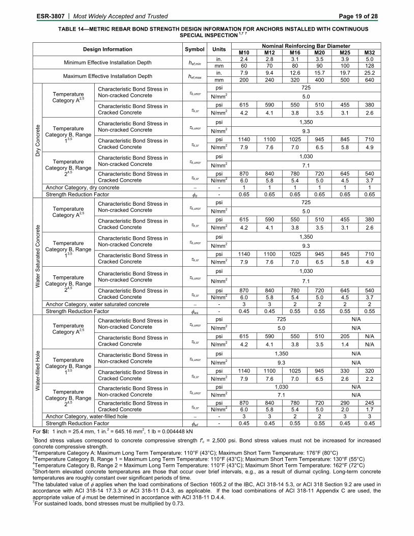
TABLE 14—METRIC REBAR BOND STRENGTH DESIGN INFORMATION FOR ANCHORS INSTALLED WITH CONTINUOUS SPECIAL INSPECTION 1,7 7
Design Information Symbol Units Nominal Reinforcing Bar Diameter
M10 M12 M16 M20 M25 M32
Minimum Effective Installation Depth hef,min in. 2.4 2.8 3.1 3.5 3.9 5.0
mm 60 70 80 90 100 128
Maximum Effective Installation Depth hef,max in. 7.9 9.4 12.6 15.7 19.7 25.2
mm 200 240 320 400 500 640
Dry
Con
cret
e
Temperature Category A2,5
Characteristic Bond Stress in Non-cracked Concrete k,uncr
psi 725
N/mm2 5.0
Characteristic Bond Stress in Cracked Concrete k,cr
psi 615 590 550 510 455 380
N/mm2 4.2 4.1 3.8 3.5 3.1 2.6
Temperature Category B, Range
13,5
Characteristic Bond Stress in Non-cracked Concrete k,uncr
psi 1,350
N/mm2 9.3
Characteristic Bond Stress in Cracked Concrete k,cr
psi 1140 1100 1025 945 845 710
N/mm2 7.9 7.6 7.0 6.5 5.8 4.9
Temperature Category B, Range
24,5
Characteristic Bond Stress in Non-cracked Concrete k,uncr
psi 1,030
N/mm2 7.1
Characteristic Bond Stress in Cracked Concrete k,cr
psi 870 840 780 720 645 540 N/mm2 6.0 5.8 5.4 5.0 4.5 3.7
Anchor Category, dry concrete - 1 1 1 1 1 1 Strength Reduction Factor d - 0.65 0.65 0.65 0.65 0.65 0.65
Wat
er S
atur
ated
Con
cret
e
Temperature Category A2,5
Characteristic Bond Stress in Non-cracked Concrete k,uncr
psi 725
N/mm2 5.0
Characteristic Bond Stress in Cracked Concrete k,cr
psi 615 590 550 510 455 380
N/mm2 4.2 4.1 3.8 3.5 3.1 2.6
Temperature Category B, Range
13,5
Characteristic Bond Stress in Non-cracked Concrete k,uncr
psi 1,350
N/mm2 9.3
Characteristic Bond Stress in Cracked Concrete k,cr
psi 1140 1100 1025 945 845 710
N/mm2 7.9 7.6 7.0 6.5 5.8 4.9
Temperature Category B, Range
24,5
Characteristic Bond Stress in Non-cracked Concrete k,uncr
psi 1,030
N/mm2 7.1
Characteristic Bond Stress in Cracked Concrete k,cr
psi 870 840 780 720 645 540 N/mm2 6.0 5.8 5.4 5.0 4.5 3.7
Anchor Category, water saturated concrete - 3 3 2 2 2 2 Strength Reduction Factor ws - 0.45 0.45 0.55 0.55 0.55 0.55
Wat
er-f
illed
Hol
e
Temperature Category A2,5
Characteristic Bond Stress in Non-cracked Concrete k,uncr
psi 725 N/A
N/mm2 5.0 N/A
Characteristic Bond Stress in Cracked Concrete k,cr
psi 615 590 550 510 205 N/A
N/mm2 4.2 4.1 3.8 3.5 1.4 N/A
Temperature Category B, Range
13,5
Characteristic Bond Stress in Non-cracked Concrete k,uncr
psi 1,350 N/A
N/mm2 9.3 N/A
Characteristic Bond Stress in Cracked Concrete k,cr
psi 1140 1100 1025 945 330 320
N/mm2 7.9 7.6 7.0 6.5 2.6 2.2
Temperature Category B, Range
24,5
Characteristic Bond Stress in Non-cracked Concrete k,uncr
psi 1,030 N/A
N/mm2 7.1 N/A
Characteristic Bond Stress in Cracked Concrete k,cr
psi 870 840 780 720 290 245 N/mm2 6.0 5.8 5.4 5.0 2.0 1.7
Anchor Category, water-filled hole - 3 3 2 2 3 3 Strength Reduction Factor wf - 0.45 0.45 0.55 0.55 0.45 0.45
For SI: 1 inch = 25.4 mm, 1 in.2 = 645.16 mm2, 1 lb = 0.004448 kN 1Bond stress values correspond to concrete compressive strength f'c = 2,500 psi. Bond stress values must not be increased for increased concrete compressive strength. 2Temperature Category A: Maximum Long Term Temperature: 110°F (43°C); Maximum Short Term Temperature: 176°F (80°C) 3Temperature Category B, Range 1 = Maximum Long Term Temperature: 110°F (43°C); Maximum Short Term Temperature: 130°F (55°C) 4Temperature Category B, Range 2 = Maximum Long Term Temperature: 110°F (43°C); Maximum Short Term Temperature: 162°F (72°C) 5Short-term elevated concrete temperatures are those that occur over brief intervals, e.g., as a result of diurnal cycling. Long-term concrete temperatures are roughly constant over significant periods of time. 6The tabulated value of applies when the load combinations of Section 1605.2 of the IBC, ACI 318-14 5.3, or ACI 318 Section 9.2 are used in accordance with ACI 318-14 17.3.3 or ACI 318-11 D.4.3, as applicable. If the load combinations of ACI 318-11 Appendix C are used, the appropriate value of must be determined in accordance with ACI 318-11 D.4.4. 7For sustained loads, bond stresses must be multiplied by 0.73.

ESR-3807 | Most Widely Accepted and Trusted Page 20 of 28
Left to right: MOPURE250, MOPURE400, MOPURE600, MOPURE1500
Mixer Nozzle MORCAPU
Mixer Nozzle MORCAPUH
Left to right: 3/8" (9 mm) Ø Y1 extension tube, 9/16" (14 mm) Ø Y2 extension tube, resin stoppers
FIGURE 2—INDEX MOPURE INJECTION SYSTEM ANCHORING SYSTEM

ESR-3807 | Most Widely Accepted and Trusted Page 21 of 28
TABLE 15—INSTALL PARAMETERS (FRACTIONAL SIZES)
Threaded Rod Installations
Anchor Size
Drilled Hole Size
Cleaning Brush Size
Nozzle Type Extension Tube Required?
Resin Stopper Required?
Notes MORCAPU MORCAPUH
3/8" 1/2" MORCE14 Y1 > 3.5" hef N
1/2" 9/16" MORCE16 Y1 > 3.5" hef N
5/8" 3/4" MORCE22 Y2 > 10" hef MORS18>10"hef
MORCAPUH nozzle required at
hef > 8" 3/4"
7/8" MORCE24 Y2 > 10" hef MORS18>10"hef 7/8" 1" MORCE27 Y2 > 10" hef MORS22>10"hef
1" 11/8" MORCE31 Y2 > 10" hef MORS22>10"hef
11/4" 13/8" MORCE38 Y2 > 10" hef MORS30>10"hef
Reinforcing Bar Installations
Anchor Size
Drilled Hole Size
Cleaning Brush Size
Nozzle Type Extension Tube Required?
Resin Stopper Required?
Notes MORCAPU MORCAPUH
#3 9/16" MORCE14 Y1 > 3.5" hef N
#4 5/8" MORCE18 Y1 > 3.5" hef N MORCAPUH nozzle
required at hef > 3.5"
#5 3/4" MORCE22 Y2 > 10" hef MORS18>10"hef MORCAPUH nozzle
required at hef > 8"
#6 7/8" MORCE27 Y2 > 10" hef MORS18>10"hef
#7 1" MORCE31 Y2 > 10" hef MORS22>10"hef
#8 11/8" MORCE35 Y2 > 10" hef MORS22>10"hef
#10 13/8" MORCE43 Y2 > 10" hef MORS30>10"hef
Key: Y1 Requires 3/8" diameter extension tube fitted to MORCAPU nozzle Y2 Requires 9/16" diameter extension tube fitted to MORCAPUH nozzle MORS18 Use 18 mm diameter resin stopper MORS22 Use 22 mm diameter resin stopper MORS30 Use 30 mm diameter resin stopper N Not required

ESR-3807 | Most Widely Accepted and Trusted Page 22 of 28
TABLE 16—INSTALL PARAMETERS (METRIC SIZES)
Threaded Rod Installations
Anchor Size
Drilled Hole Size
Cleaning Brush Size
Nozzle Type Extension Tube Required?
Resin Stopper Required?
Notes MORCAPU MORCAPUH
M10 12 MORCE14 Y1 >90 mm hef N
M12 14 MORCE16 Y1 > 90 mm hef N
M16 18 MORCE22 Y2 > 250 mm hef MORS18> 250 mm hef
MORCAPUH nozzle required at hef > 200
mm
M20 22 MORCE24 Y2 > 250 mm hef MORS18>
250 mm hef
M24 26 MORCE31 Y2 > 250 mm hef MORS22>
250 mm hef
M30 35 MORCE38 Y2 > 250 mm hef MORS30>
250 mm hef
Reinforcing Bar Installations
Anchor Size
Drilled Hole Size
Cleaning Brush Size
Nozzle Type Extension Tube Required?
Resin Stopper Required?
Notes MORCAPU MORCAPUH
T10 14 MORCE16 Y1 > 90 mm hef N
T12 16 MORCE18 Y1 > 90 mm hef N MORCAPUH nozzle required at hef > 90
mm
T16 20 MORCE22 Y2 > 250 mm hef MORS18> 250 mm hef
MORCAPUH nozzle required at hef > 200
mm
T20 25 MORCE27 Y2 > 250 mm hef MORS22> 250 mm hef
T25 32 MORCE36 Y2 > 250 mm hef MORS22> 250 mmhef
T32 40 MORCE43 Y2 > 250 mm hef MORS30> 250 mm hef
Key: Y1 Requires 10 mm diameter extension tube fitted to MORCAPU nozzle Y2 Requires14 mm diameter extension tube fitted to MORCAPUH nozzle MORS18 Use 18 mm diameter resin stopper MORS22 Use 22 mm diameter resin stopper MORS30 Use 30 mm diameter resin stopper N Not required

ESR-3807 | Most Widely Accepted and Trusted Page 23 of 28
TABLE 17—ALLOWABLE COMBINATIONS OF CARTRIDGE, MIXER NOZZLE AND DISPENSING TOOL
Cartridge Reference Allowable Applicator Tools Allowable Nozzle Types
MORCAPU MORCAPUH
MOPURE250
Cox 300 mL Manual
(26:1 mechanical advantage)
MOPURE400
Cox 400 mL Manual
(26:1 mechanical advantage)
MOPURE600
Newborn 600 mL Manual
(26:1 mechanical advantage)
Newborn 600 mL Pneumatic
MOPURE1500
Newborn 1500 mL Pneumatic
TABLE 18—GEL AND CURE TIMES1
Substrate Temperature (°C) Substrate Temperature (°F) Gel Time Cure Time
4 to 9 40 to 49 20 mins
24 hours 10 to 15 50 to 59 12 hours 15 to 22 59 to 72 15 mins 8 hours 22 to 25 72 to 77 11 mins 7 hours 25 to 30 77 to 86 8 mins 6 hours 30 to 35 86 to 95 6 mins 5 hours 35 to 40 95 to 104 4 mins 4 hours
40 104 3 mins 3 hours 1Cartridge must be conditioned to a minimum 10°C / 50°F

ESR-3807 | Most Widely Accepted and Trusted Page 24 of 28 INDEX MOPURE INJECTION SYSTEM: MPII Before commencing installation ensure the installer is equipped with appropriate personal protection equipment, SDS Hammer Drill, Air Lance, Hole Cleaning Brush, good quality dispensing tool – either manual or power operated, adhesive cartridge with mixing nozzle, and extension tube with resin stopper as required in Tables 15 and 16. Refer to Figure 2, Table 1, Table 15, Table 16, and Table 17 for parts specification or guidance for individual items or dimensions. Important: check the expiration date on the cartridge (do not use expired material) and that the cartridge has been stored in its original packaging, the correct way up, in cool conditions (50°F to 77°F) out of direct sunlight. Solid Substrate Installation Method 1. Using the SDS Hammer Drill
in rotary hammer mode for drilling, with a carbide tipped drill bit conforming to ANSI B212.15-1994 of the appropriate size, drill the hole to the specified hole diameter and depth.
2. Select the correct Air Lance, insert to the bottom of the hole and depress the trigger for 2 seconds. The compressed air must be clean – free from water and oil – and at a
minimum pressure of 90 psi (6 bar). Perform the blowing operation twice. 3. Select the correct size Hole
Cleaning Brush. Ensure that the brush is in good condition and the correct diameter. Insert the brush to the bottom of the hole, using a brush
extension if needed to reach the bottom of the hole and withdraw with a twisting motion. There should be positive interaction between the steel bristles of the brush and the sides of the drilled hole.
Perform the brushing operation twice. 4. Repeat 2 (blowing operation) twice.
5. Repeat 3 (brushing operation) twice.
6. Repeat 2 (blowing operation) twice.
7. Select the appropriate static mixer nozzle, checking that the mixing elements are present and correct (do not modify the mixer). Attach mixer nozzle to the cartridge. Check the Dispensing Tool is in good working order. Place the cartridge into the dispensing tool.
Note: The MORCAPUH nozzle is in two sections. One section contains the mixing elements and the other section is an extension piece. Connect the extension piece to the mixing section by pushing the two sections firmly together until a positive engagement is felt.
Note: Index MOPURE Injection
System may only be installed between concrete temperatures of 40°F to 104°F for horizontal to downward installation direction, and 50°F to 104°F for horizontal to overhead direction. The product must be conditioned to a minimum of 50°F. For gel and cure time data, refer to Table 14.
8. Extrude some resin to waste until an even-colored mixture is extruded, The cartridge is now ready
for use.
9. As specified in Figure 2, Table 11, and Table 12, attach an extension tube with resin stopper (if required) to the end of the mixing nozzle with a push fit.
(The extension tubes may be pushed into the resin stoppers and are held in place with a coarse internal thread).
10. Insert the mixing nozzle to the
bottom of the hole. Extrude the resin and slowly withdraw the nozzle from the hole. Ensure no air voids are created as the nozzle is withdrawn. Inject resin until
the hole is approximately ½ to ¾ full and remove the nozzle from the hole.
11. Select the steel anchor
element ensuring it is free from oil or other contaminants, and mark with the required embedment depth. Insert the steel element into the hole using a back and forth twisting
motion to ensure complete cover, until it reaches the bottom of the hole. Adhesive must completely fill the annular gap between the steel element and the concrete. Excess resin will be expelled from the hole evenly around the steel element and there shall be no gaps between the anchor element and the wall of the drilled hole.
12. Clean any excess resin from around the mouth of the
hole. 13. Do not disturb the anchor until
at least the minimum cure time has elapsed. Refer to the Table 14 Gel and Cure Times to determine the appropriate cure time.
14. Position the fixture and tighten the anchor to the appropriate installation torque.
Do not over-torque the
anchor as this could adversely affect its performance.
FIGURE 3—INSTALLATION DETAILS
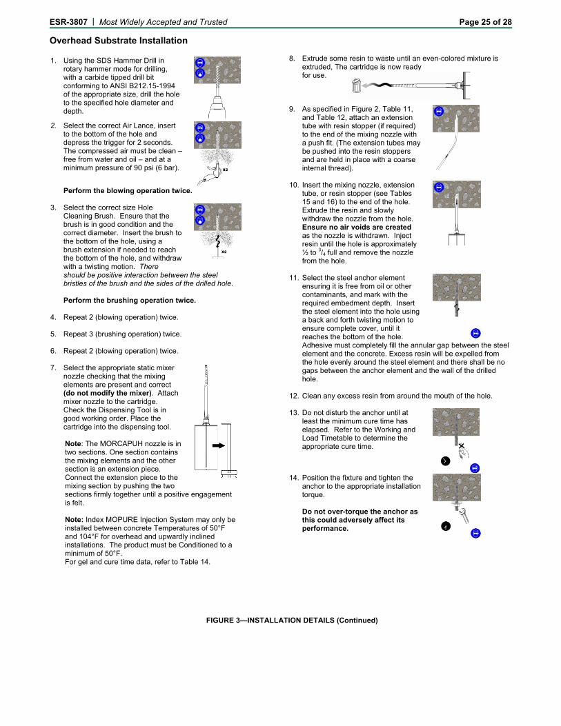
ESR-3807 | Most Widely Accepted and Trusted Page 25 of 28 Overhead Substrate Installation 1. Using the SDS Hammer Drill in
rotary hammer mode for drilling, with a carbide tipped drill bit conforming to ANSI B212.15-1994 of the appropriate size, drill the hole to the specified hole diameter and depth.
2. Select the correct Air Lance, insert to the bottom of the hole and depress the trigger for 2 seconds. The compressed air must be clean – free from water and oil – and at a minimum pressure of 90 psi (6 bar).
Perform the blowing operation twice. 3. Select the correct size Hole
Cleaning Brush. Ensure that the brush is in good condition and the correct diameter. Insert the brush to the bottom of the hole, using a brush extension if needed to reach the bottom of the hole, and withdraw with a twisting motion. There
should be positive interaction between the steel bristles of the brush and the sides of the drilled hole.
Perform the brushing operation twice. 4. Repeat 2 (blowing operation) twice.
5. Repeat 3 (brushing operation) twice.
6. Repeat 2 (blowing operation) twice.
7. Select the appropriate static mixer nozzle checking that the mixing elements are present and correct (do not modify the mixer). Attach mixer nozzle to the cartridge. Check the Dispensing Tool is in good working order. Place the cartridge into the dispensing tool.
Note: The MORCAPUH nozzle is in two sections. One section contains the mixing elements and the other section is an extension piece. Connect the extension piece to the mixing section by pushing the two sections firmly together until a positive engagement is felt.
Note: Index MOPURE Injection System may only be installed between concrete Temperatures of 50°F and 104°F for overhead and upwardly inclined installations. The product must be Conditioned to a minimum of 50°F. For gel and cure time data, refer to Table 14.
8. Extrude some resin to waste until an even-colored mixture is
extruded, The cartridge is now ready for use.
9. As specified in Figure 2, Table 11, and Table 12, attach an extension tube with resin stopper (if required) to the end of the mixing nozzle with a push fit. (The extension tubes may be pushed into the resin stoppers and are held in place with a coarse internal thread).
10. Insert the mixing nozzle, extension tube, or resin stopper (see Tables 15 and 16) to the end of the hole. Extrude the resin and slowly withdraw the nozzle from the hole. Ensure no air voids are created as the nozzle is withdrawn. Inject resin until the hole is approximately ½ to 3/4 full and remove the nozzle from the hole.
11. Select the steel anchor element ensuring it is free from oil or other contaminants, and mark with the required embedment depth. Insert the steel element into the hole using a back and forth twisting motion to ensure complete cover, until it reaches the bottom of the hole.
Adhesive must completely fill the annular gap between the steel element and the concrete. Excess resin will be expelled from the hole evenly around the steel element and there shall be no gaps between the anchor element and the wall of the drilled hole.
12. Clean any excess resin from around the mouth of the hole. 13. Do not disturb the anchor until at
least the minimum cure time has elapsed. Refer to the Working and Load Timetable to determine the appropriate cure time.
14. Position the fixture and tighten the anchor to the appropriate installation torque.
Do not over-torque the anchor as
this could adversely affect its performance.
FIGURE 3—INSTALLATION DETAILS (Continued)

ESR-3807 | Most Widely Accepted and Trusted Page 26 of 28
TABLE 19—EXAMPLE OF ALOWABLE STRESS DESIGN (ASD) TENSION VALUES FOR ILLUSTRATIVE PURPOSES
Example Allowable Stress Design (ASD) Calculation for Illustrative Purposes
Anchor Diameter (in.)
Embedment Depth Max / Min (in.)
Characteristic Bond Strength k,uncr (psi)
Allowable Tension Load (lb) 2500 psi - 8000 psi Concrete
Controlling Failure Mode
3/8" 2.375 1,350 1,929 Breakout Strength
7.50 1,350 4,910 Steel Strength
1/2" 2.75 1,350 2,403 Breakout Strength
10.00 1,350 8,990 Steel Strength
5/8" 3.125 1,350 2,911 Breakout Strength
12.50 1,350 14,316 Steel Strength
3/4" 3.50 1,350 3,451 Breakout Strength
15.00 1,350 21,157 Steel Strength
7/8" 4.00 1,350 4,216 Breakout Strength
17.50 1,350 29,265 Steel Strength
1" 4.00 1,350 4,216 Breakout Strength
20.00 1,350 38,387 Steel Strength
11/4" 4.00 1,350 4,216 Breakout Strength
25.00 1,350 61,381 Steel Strength
Design Assumptions: 1. Single anchor in static tension only, Grade B7 threaded rod. 2. Vertical downwards installation. 3. Inspection regimen = Periodic. 4. Installation temperature 70F to 110F 5. Long term temperature 110F 6. Short term temperature 130F 7. Dry condition (carbide drilled hoe). 8. Embedment (hef) = min / max for each diameter. 9. Concrete determined to remain uncracked for life of anchor.
10. Load combinations from ACI 318-11 Section 9.2 (no seismic loading). 11. 30% dead load and 70% live load. Controlling load combination 1.2D + 1.6L 12. Calculation of weighted average for α = 1.2(0.3) + 1.6(0.7) = 1.48 13. f'c = 2500 psi (normal weight concrete) 14. cac1 = cac2 ≥ cac 15. h ≥ hmin

ESR-3807 | Most Widely Accepted and Trusted Page 27 of 28
Illustrative Procedure to Calculate Allowable Stress Design Tension Value Index MOPURE Injection System Anchor 1/2" Diameter, using an embedment of 2.75", with the design
assumptions given in Table 19 (for use with the 2012 IBC, based on ACI 318-11 Appendix D)
Procedure Calculation
Step 1: Calculate steel strength of a single anchor in tension per ACI 318 D.5.1.2 (Table 2 of this report).
Nsa = Nsa =0.65 x 17740 =11531 lb
Step 2: Calculate breakout strength of a single Nb = kc,uncr a √(f'c) hef1.5
anchor in tension per ACI 318 D.5.2 (Table 5 of this report). =(24) x(1.0) x (2500)0.5 x (2.75)1.5
=5472 lb
Ncb = (ANC / ANC0)ψed,N ψc,Nψcp,N Nb =0.65 x 1.0 x 1.0 x 1.0 x 1.0 x 5472
=3557 lb
Step 3: Calculate bond strength of a single anchor in tension per ACI 318 D.5.5 Nba a k,uncr π d hef (Table 8 of this report). =1.0 x 1350 x 3.141 x 0.5 x 2.75 =5830 lb
Na = (ANa / ANa0)ψed,Na ψcp,Na Nba =0.65 x 1.0 x 1.0 x 1.0 x 5830 =3789 lb
Step 4: Determine controlling resistance strength 3557 lb = controlling resistance in tension per ACI 318 D 4.1.1 and D 4.1.2. (breakout)
Step 5: Calculate Allowable Stress Design α = 1.2DL + 1.6LL conversion factor for loading condition per ACI 318 Section 9.2. = 1.2*0.3 + 1.6*0.7
= 1.48
Step 6: Calculate Allowable Stress Design value Tallowable,ASD = 3557 / 1.48 per Section 4.2 of this report. = 2403 lb
FIGURE 4—SAMPLE CALCULATIONS

ICC-ES Evaluation Reports are not to be construed as representing aesthetics or any other attributes not specifically addressed, nor are they to be construed as an endorsement of the subject of the report or a recommendation for its use. There is no warranty by ICC Evaluation Service, LLC, express or implied, as to any finding or other matter in this report, or as to any product covered by the report.
Copyright © 2018 ICC Evaluation Service, LLC. All rights reserved. Page 28 of 28
ICC-ES Evaluation Report ESR-3807 FBC Supplement Reissued August 2017
Revised March 19, 2018
This report is subject to renewal August 2019.
www.icc-es.org | (800) 423-6587 | (562) 699-0543 A Subsidiary of the International Code Council ®
DIVISION: 03 00 00—CONCRETE Section: 03 16 00—Concrete Anchors DIVISION: 05 00 00—METALS Section: 05 05 19—Post-Installed Concrete Anchors REPORT HOLDER: TECNICAS EXPANSIVAS S.L. C/SEGADOR 13 26006 LOGRONO (LA RIOJA) SPAIN 34 941 272 131 www.indexfix.com [email protected] EVALUATION SUBJECT: INDEX MOPURE INJECTION SYSTEM ANCHORS FOR CRACKED AND UNCRACKED CONCRETE 1.0 REPORT PURPOSE AND SCOPE
Purpose:
The purpose of this evaluation report supplement is to indicate that Index MOPURE Injection System Anchors for Cracked and Uncracked Concrete, recognized in ICC-ES master evaluation report ESR-3807, have also been evaluated for compliance with the codes noted below.
Applicable code editions:
2014 Florida Building Code—Building
2014 Florida Building Code—Residential
2.0 CONCLUSIONS
The Index MOPURE Injection System Anchors for Cracked and Uncracked Concrete, described in Sections 2.0 through 7.0 of the master evaluation report ESR-3807, comply with the Florida Building Code—Building and the Florida Building Code—Residential, provided the design and installation are in accordance with the 2012 International Building Code® (IBC) provisions noted in the master report and the following provisions apply:
Design wind loads must be based on Section 1609 of the Florida Building Code—Building or Section 301.2.1.1 of the Florida Building Code—Residential, as applicable.
Load combinations must be in accordance with Section 1605.2 or Section 1605.3 of the Florida Building Code—Building, as applicable.
Use of the Index MOPURE Injection System Anchors for Cracked and Uncracked Concrete for compliance with the High-Velocity Hurricane Zone provisions of the Florida Building Code—Building has not been evaluated, and is outside the scope of this supplemental report.
For products falling under Florida Rule 9N-3, verification that the report holder’s quality assurance program is audited by a quality assurance entity approved by the Florida Building Commission for the type of inspections being conducted is the responsibility of an approved validation entity (or the code official, when the report holder does not possess an approval by the Commission).
This supplement expires concurrently with the master report, reissued August 2017 and revised March 19, 2018.