eve screen designer 4.0 user guide - brtchip.com · hal hardware abstraction layer is a software...
TRANSCRIPT

US
ER
GU
IDE
Neither the whole nor any part of the information contained in, or the product described in this manual, may be adapted or
reproduced in any material or electronic form without the prior written consent of the copyright holder. This product and
its documentation are supplied on an as-is basis and no warranty as to their suitability for any particular purpose is either
made or implied. Bridgetek Pte Ltd will not accept any claim for damages howsoever arising as a result of use or failure of
this product. Your statutory rights are not affected. This product or any variant of it is not intended for use in any medical
appliance, device or system in which the failure of the product might reasonably be expected to result in personal injury.
This document provides preliminary information that may be subject to change without notice. No freedom to use patents
or other intellectual property rights is implied by the publication of this document. Bridgetek Pte Ltd, 178, Paya Lebar
Road, #07-03, Singapore 409030. Singapore Registered Company Number 201542387H. © Bridgetek Pte Ltd.
EVE Screen Designer 4.0
Document Version: Draft 1.0
Date: 19-10-2017

Product Page 2 Document Feedback Copyright © Bridgetek Pte Ltd
Contents
I Preface..................................................................................................... 7
A. Purpose.................................................................................................................. 7
B. Intended Audience ................................................................................................. 7
C. Related Documents ................................................................................................ 7
D. Feedback ................................................................................................................ 7
II Overview ................................................................................................. 8
A. Introduction ........................................................................................................... 8
B. Key Features .......................................................................................................... 8
C. New Features in ESD 4.0 ......................................................................................... 9
D. Known Issues & Limitations .................................................................................. 10
E. Terms & Description ............................................................................................. 11
F. Credits ................................................................................................................. 11
III Setup & Installation ............................................................................... 12
A. System Requirements .......................................................................................... 12
B. Hardware Requirements ...................................................................................... 12
C. Dependencies / Pre-Requisites ............................................................................. 13
D. Installing ESD 4.0 .................................................................................................. 14
E. Installation Folder ................................................................................................ 18
IV Working with ESD 4.0 ............................................................................. 19
A. What’s new in ESD 4.0? ........................................................................................ 19
Widget model ................................................................................................................................ 19
Layout Feature .............................................................................................................................. 20
Project Extension Name (*.esd) .................................................................................................... 20
Depth Sort Property ...................................................................................................................... 21
Depth Sort as rendering order ................................................................................................................. 21
Depth Sort as layout sequencing control ................................................................................................. 22
Depth Sort as page sequencing in “Switch Page” .................................................................................... 22
B. Impacts of ESD 4.0 Updated Features ................................................................... 23
C. Migrating from ESD 3.0 to ESD 4.0 project ............................................................ 23
D. Setting Platform Specific Properties ...................................................................... 24

BRT_AN_021 EVE Screen Designer 4.0 User Guide Version 1.0 Document Reference No.: BRT_000180
Clearance No.: BRT#098
Product Page 3
Document Feedback Copyright © Bridgetek Pte Ltd
V Getting Started ...................................................................................... 26
A. The Graphical User Interface ................................................................................ 26
1 Menu bar ............................................................................................................................... 27
2 Toolbar .................................................................................................................................. 29
3 Project Explorer..................................................................................................................... 30
4 Screen Layout Editor ............................................................................................................. 31
5 Logic Node Editor .................................................................................................................. 32
6 Library Browser ..................................................................................................................... 32
7 Error List ................................................................................................................................ 33
8 Output ................................................................................................................................... 34
9 Property Editor ...................................................................................................................... 34
10 Status bar .......................................................................................................................... 35
B. Application Project Structure ................................................................................ 36
C. ESD Workflow ...................................................................................................... 37
Design Layout using Layout Editor ................................................................................................ 38
Custom Widget ........................................................................................................................................ 38
Add Bitmap Resource .............................................................................................................................. 38
Configure Bitmap Resource ..................................................................................................................... 39
Design Screen Logic using Logic Node Editor ................................................................................ 40
Simulate ........................................................................................................................................ 41
Build & Upload .............................................................................................................................. 41
Export ............................................................................................................................................ 41
Exported Folder Structure ........................................................................................................................ 42
Bitmap Resource ...................................................................................................................................... 42
D. Layout Editor ........................................................................................................ 43
Page File ........................................................................................................................................ 43
“Active” Property ..................................................................................................................................... 43
Switch Page ............................................................................................................................................. 43
Page Persistence ...................................................................................................................................... 44
User Defined Function for Page File......................................................................................................... 45
Zoom In & Out ......................................................................................................................................... 45
Main File ........................................................................................................................................ 46
Logic File ........................................................................................................................................ 47
C File .............................................................................................................................................. 47
E. Logic Note Editor .................................................................................................. 48
Basic Logic Node ........................................................................................................................... 48
Composite Logic Node .................................................................................................................. 48
Page Node ............................................................................................................................................... 49
Widget Node ............................................................................................................................................ 50
Adding User Widgets ........................................................................................................................... 50
Position & Size Properties ................................................................................................................... 51

BRT_AN_021 EVE Screen Designer 4.0 User Guide Version 1.0 Document Reference No.: BRT_000180
Clearance No.: BRT#098
Product Page 4
Document Feedback Copyright © Bridgetek Pte Ltd
Rendering a widget ............................................................................................................................. 51
Theme ................................................................................................................................................. 52
Touch Input ......................................................................................................................................... 52
Layout Type Widget ................................................................................................................................. 52
Actor Node ............................................................................................................................................... 53
Logic Object ............................................................................................................................................. 54
Connections .................................................................................................................................. 54
Rendering Order ........................................................................................................................... 55
Logic Note Editor - Zoom In & Zoom Out ...................................................................................... 56
F. Library Browser .................................................................................................... 57
ESD Layouts ................................................................................................................................... 57
Switch Page ............................................................................................................................................. 58
Fixed Positioning ...................................................................................................................................... 59
Fill Layout................................................................................................................................................. 60
Linear Layout ........................................................................................................................................... 61
Stretch ..................................................................................................................................................... 63
Scroll Layout ............................................................................................................................................ 64
ESD Render Functions ................................................................................................................... 65
Elements .................................................................................................................................................. 65
ESD Circle ............................................................................................................................................ 65
ESD Panel ............................................................................................................................................ 66
ESD Gradient Panel ............................................................................................................................. 66
Primitives ................................................................................................................................................. 67
ESD Bitmap .......................................................................................................................................... 67
ESD Line ............................................................................................................................................... 69
ESD Rectangle ..................................................................................................................................... 70
Display List ............................................................................................................................................... 70
ESD Theme .................................................................................................................................... 71
Built In Themes ........................................................................................................................................ 71
ESD Utilities ................................................................................................................................... 73
ESD Widgets .................................................................................................................................. 74
Basic Widgets .......................................................................................................................................... 74
ESD Line Widget .................................................................................................................................. 75
ESD Circle Widgets .............................................................................................................................. 75
ESD Panel Widgets .............................................................................................................................. 76
ESD Gradient Widget ........................................................................................................................... 77
ESD Check Box.......................................................................................................................................... 78
ESD Clock ................................................................................................................................................. 78
ESD Color Picker ....................................................................................................................................... 80
ESD Gauge ............................................................................................................................................... 81
ESD Image ................................................................................................................................................ 82
ESD Image Button .................................................................................................................................... 83
ESD Image Rotate .................................................................................................................................... 84
ESD Label ................................................................................................................................................. 85
ESD Numeric Label ................................................................................................................................... 86

BRT_AN_021 EVE Screen Designer 4.0 User Guide Version 1.0 Document Reference No.: BRT_000180
Clearance No.: BRT#098
Product Page 5
Document Feedback Copyright © Bridgetek Pte Ltd
ESD Fixed Point Label ............................................................................................................................... 87
ESD Label Button ..................................................................................................................................... 88
ESD Radio Button and ESD Radio Group .................................................................................................. 89
ESD Push Button ...................................................................................................................................... 91
ESD Progress Bar ..................................................................................................................................... 92
ESD Slider ................................................................................................................................................. 93
ESD Scroll Bar ........................................................................................................................................... 95
ESD Scroll Panel ....................................................................................................................................... 96
ESD Scrollable Image ............................................................................................................................... 97
Touch Control Mode ........................................................................................................................... 98
Slide Control Mode ............................................................................................................................. 99
ESD Sketch ............................................................................................................................................. 100
ESD Spin Box .......................................................................................................................................... 101
ESD Toggle ............................................................................................................................................. 103
Logic Flow .................................................................................................................................... 104
Condition ............................................................................................................................................... 105
Binary Condition .................................................................................................................................... 105
Binary Operator ..................................................................................................................................... 106
Ternary Operator ................................................................................................................................... 107
Unary Operator...................................................................................................................................... 107
Sequence ................................................................................................................................................ 108
Switch Node ........................................................................................................................................... 108
Switch Value .......................................................................................................................................... 109
Set Variable ........................................................................................................................................... 109
Watch Variables .................................................................................................................................... 110
Logic Interface ............................................................................................................................. 111
Input ...................................................................................................................................................... 111
Output ................................................................................................................................................... 112
Signal ..................................................................................................................................................... 112
Slot ......................................................................................................................................................... 113
Built-in Slot ........................................................................................................................................ 113
Variable ................................................................................................................................................. 114
Writer .................................................................................................................................................... 114
Widget Interface .................................................................................................................................... 115
G. Property Editor .................................................................................................. 117
Common Properties .................................................................................................................... 117
Name ..................................................................................................................................................... 118
Depth Sort .............................................................................................................................................. 118
Active ..................................................................................................................................................... 119
H. Programming Features ....................................................................................... 120
Macros ........................................................................................................................................ 120
ESD_TYPE ............................................................................................................................................... 120
ESD_ENUM ............................................................................................................................................ 121
ESD_FUNCTION ...................................................................................................................................... 122
ESD_METHOD ........................................................................................................................................ 123

BRT_AN_021 EVE Screen Designer 4.0 User Guide Version 1.0 Document Reference No.: BRT_000180
Clearance No.: BRT#098
Product Page 6
Document Feedback Copyright © Bridgetek Pte Ltd
ESD_INPUT ............................................................................................................................................. 124
ESD_OUTPUT ......................................................................................................................................... 125
ESD_UPDATE.......................................................................................................................................... 125
Pre-compiler options .................................................................................................................. 125
ESD_SIMULATION .................................................................................................................................. 125
FT900_PLATFORM ................................................................................................................................. 125
Add User Functions ..................................................................................................................... 126
Creating Source File ............................................................................................................................... 126
Editing the Source File ........................................................................................................................... 126
Appendix A – List of Figures ....................................................................... 128
Appendix B – List of Tables ........................................................................ 130
Appendix C – Revision History .................................................................... 132

BRT_AN_021 EVE Screen Designer 4.0 User Guide Version 1.0 Document Reference No.: BRT_000180
Clearance No.: BRT#098
Product Page 7
Document Feedback Copyright © Bridgetek Pte Ltd
I Preface
A. Purpose
This document describes the functionality and procedures involved in using the EVE
Screen Designer (ESD) 4.0.
B. Intended Audience
The intended audience shall be any GUI application developer working with EVE
products.
C. Related Documents
Document Name Document Type Document Format
FT81x Series Programmers Guide Programming Guide PDF
FT81x Datasheet Datasheet PDF
FT9xx Toolchain Installation Guide Installation Guide PDF
D. Feedback
Every effort has been taken to ensure that the document is accurate and complete.
However any feedback on the document may be emailed to [email protected].
For any additional technical support, refer to http://brtchip.com/contact-us/.

BRT_AN_021 EVE Screen Designer 4.0 User Guide Version 1.0 Document Reference No.: BRT_000180
Clearance No.: BRT#098
Product Page 8
Document Feedback Copyright © Bridgetek Pte Ltd
II Overview
A. Introduction
EVE Screen Designer (ESD) is the next generation of smart IDE for EVE, making EVE-
based GUI development much easier to accomplish. This tool enables users to build one
GUI application using a visual programming1 method without needing to know any
EVE-specific display list commands.
ESD provides a WYSIWYG (“What You See Is What You Get”) environment for editing
graphics, designing visual effects, and defining GUI application user logic,
generating ANSI C code for the targeted hardware platform. Users can also choose to
simulate the whole design to experience the UI before compiling and downloading the
generated source code. Furthermore, ESD has the capability to work seamlessly with
Bridgetek FT9XX tool chain. User can compile, link the generated source code with
FT9XX tool chain and upload it to the targeted platform without leaving ESD.
ESD 4.0 introduces layout mechanism to manage widgets and pages in a more generic
way. The layout mechanism will enable users to create more dynamic UI much easier
than before. In addition, ESD 4.0 dramatically enhances the functionality of logic nodes
editor, layout editor and project browser, for better user experience.
B. Key Features
The following are some of the key features of EVE Screen Designer:
WYSIWYG GUI
High level widgets
No EVE display list knowledge required
Widget based GUI construction
Drag and drop widget to create screen layout
Inter widget communication
Screen logic creation without coding
Simulation of screen logic and user touch input using mouse
Building and downloading the generated “C” code (if FT9XX Toolchain is installed)
1 https://en.wikipedia.org/wiki/Visual_programming_language

BRT_AN_021 EVE Screen Designer 4.0 User Guide Version 1.0 Document Reference No.: BRT_000180
Clearance No.: BRT#098
Product Page 9
Document Feedback Copyright © Bridgetek Pte Ltd
C. New Features in ESD 4.0
Introduced layout type widget to manage the widget’s layout effectively
Support for platform configuration when creating new project
Switch platform when multiple platforms are supported in current project
Added resource folder in project browser when adding images into project
Enable creating subfolder in project browser for better resource management
Added more built-in logic nodes to ease the logic creation
Added default theme file in newly created project
Added optimization in FT9XX tool chain configuration script to reduce code size
Enable string find/replace functionality in the C file editor
Support group selection and area selection in logic node editor and layout editor
Support cut/copy/paste operation on nodes level
Support screen resolution specific widget properties configuration
Support PALETTED8,DXT1, PNG2, JPEG3 format in ESD Image widget
Enabled log facility for debugging purpose
2 PNG file shall conform to the requirement of EVE command CMD_LOADIMAGE
3 JPEG file shall conform to the requirement of EVE command CMD_LOADIMAGE
BRT_AN_021 EVE Screen Designer 4.0 User Guide Version 1.0 Document Reference No.: BRT_000180
Clearance No.: BRT#098
Product Page 10
Document Feedback Copyright © Bridgetek Pte Ltd
D. Known Issues & Limitations
The following are some known issues and limitations of ESD:
Only the FT81X series EVE is supported. FT80X Series EVE is NOT supported
The C code editor in ESD does not support all the features of a code editor.
Video feature is not supported.
If the project file path is too long (i.e. more than 512 bytes), ESD may have a
problem opening it. The typical error message is shown below:
“Unable to generate output files, check directory permission at:
C:\Users\xxxx.xxxx\Project\ESD\......”
Where
“C:\Users\xxxx.xxxx\Project\ESD\......” refers to the project folder.
Logic node editor background goes white after windows hibernate.
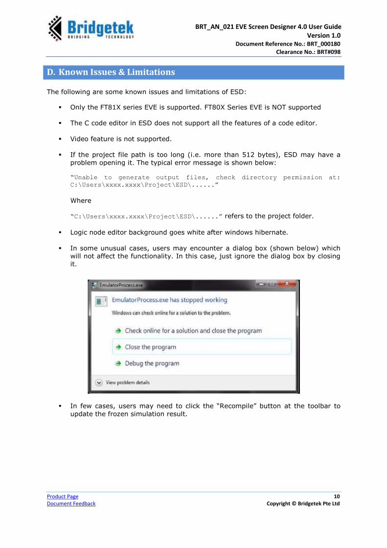
In some unusual cases, users may encounter a dialog box (shown below) which
will not affect the functionality. In this case, just ignore the dialog box by closing
it.
In few cases, users may need to click the “Recompile” button at the toolbar to
update the frozen simulation result.

BRT_AN_021 EVE Screen Designer 4.0 User Guide Version 1.0 Document Reference No.: BRT_000180
Clearance No.: BRT#098
Product Page 11
Document Feedback Copyright © Bridgetek Pte Ltd
E. Terms & Description
Abbreviations/Term Description
Actor One type of logic node which is regularly updated but without visual appearance
DLL Dynamic Link Library is a collection of small programs, any of which can be called when needed by a larger program that is running in the computer
ESD EVE Screen Designer
EVE Emulator Bridgetek behaviour-modelling software for EVE Series chip
HAL Hardware Abstraction Layer is a software subsystem providing hardware abstraction.
IDE Integrated Development Environment
Layout type widget One type of widget which has no visual appearance rendered by EVE , but
manage the associated widget
Logic Node The node expressing certain logics.(Also referred to simply as “node” in this document)
Logic Node Editor The place create logics by connecting the logic node
Page One single screen in design
Simulation Preview the project or page by running the generated C code on PC
Widget One type of logic node which has visual appearance rendered by EVE
F. Credits
Open Source Software
Qt: http://doc.qt.io/qt-5/licensing.html under LGPL.
TinyCC: http://bellard.org/tcc/ and http://repo.or.cz/tinycc.git available under LGPL.
Errorlist module: https://github.com/kaetemi/errorlist available under MIT license
QScintilla: part of PyQt available under PyQt commercial license
https://www.riverbankcomputing.com/commercial/license-faq
Icons Copyright
Some of the icons used in ESD 4.0 are from:
http://p.yusukekamiyamane.com/icons/search/fugue/ used in compliance with the
Creative Commons Attribution 3.0 License.
BRT_AN_021 EVE Screen Designer 4.0 User Guide Version 1.0 Document Reference No.: BRT_000180
Clearance No.: BRT#098
Product Page 12
Document Feedback Copyright © Bridgetek Pte Ltd
III Setup & Installation
A. System Requirements
To install ESD 4.0 application, ensure that your system meets the requirements
recommended below:
Ideally Windows 10; alternatively Windows 8 or 7 with the latest windows
updates
1.6GHz or faster processor
1GB of RAM (1.5GB if running on a virtual machine)
Multi-Core CPU is highly recommended
At least 512MB hard disk space
Display resolution 1080 x 800 pixels or higher
“Write” permission to the installation folder
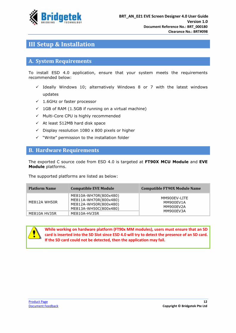
B. Hardware Requirements
The exported C source code from ESD 4.0 is targeted at FT90X MCU Module and EVE
Module platforms.
The supported platforms are listed as below:
Platform Name Compatible EVE Module Compatible FT90X Module Name
ME812A WH50R
ME810A-WH70R(800x480) ME811A-WH70R(800x480) ME812A-WH50R(800x480) ME813A-WH50C(800x480)
MM900EV-LITE MM900EV1A MM900EV2A MM900EV3A
ME810A HV35R ME810A-HV35R
While working on hardware platform (FT90x MM modules), users must ensure that an SD card is inserted into the SD Slot since ESD 4.0 will try to detect the presence of an SD card. If the SD card could not be detected, then the application may fail.

BRT_AN_021 EVE Screen Designer 4.0 User Guide Version 1.0 Document Reference No.: BRT_000180
Clearance No.: BRT#098
Product Page 13
Document Feedback Copyright © Bridgetek Pte Ltd
C. Dependencies / Pre-Requisites
Visual C++ Redistributable for Visual Studio 2015
If the PC does not have Microsoft Visual Studio 2015 installed, Visual C++
Redistributable is required. Users can download this from:
https://www.microsoft.com/en-sg/download/details.aspx?id=48145
Windows 10 Universe C Runtime
ESD has run-time dependency on Windows 10 Universe C Runtime (CRT). You may
download it from https://www.microsoft.com/en-us/download/details.aspx?id=48234
and install on your PC should the following problem be encountered:
Figure 1 - Screen Designer - System Error
FT9XX Tool Chain Version 2.1.0 or later
To compile and build projects, the FT9XX Tool Chain 2.1.0 must be installed on the
PC. It is downloadable from http://brtchip.com/ft90x-toolchain/.
Please ensure that the Tool Chain executable path is defined by the system PATH
environment variable.
Users are advised to check the known issues and limitations (of FT9XX Toolchain)
while building the ESD 4.0 project with FT9XX Toolchain. The respective FT9XX
Toolchain package version release note contains the list of known issues and
limitations.
For ESD 4.0, we recommend users to install FT9XX Tool Chain version 2.4.0 for best
result.

BRT_AN_021 EVE Screen Designer 4.0 User Guide Version 1.0 Document Reference No.: BRT_000180
Clearance No.: BRT#098
Product Page 14
Document Feedback Copyright © Bridgetek Pte Ltd
D. Installing ESD 4.0
The following steps will guide you through the ESD 4.0 Setup/Installation process.
i. Download the package from www.brtchip.com.
ii. When prompted with a download dialog box. Click on Save.
iii. Navigate to the folder under which the package files are downloaded.
iv. Extract the zip file contents. Double click on the executable file – EVE Screen
Designer 4.0.exe
v. The EVE Screen Designer Setup Wizard is displayed along with a Welcome
message.
vi. Click Next to view the end user information window.

BRT_AN_021 EVE Screen Designer 4.0 User Guide Version 1.0 Document Reference No.: BRT_000180
Clearance No.: BRT#098
Product Page 15
Document Feedback Copyright © Bridgetek Pte Ltd
vii. Click Next to select a “Destination Folder” for installing the files. Accept the
default folder or click Browse to specify a different location. Click Next to confirm
the destination folder and continue.
viii. Click Next to select a “folder” for creating the program shortcut. Accept the
default folder or click Browse, to specify a different location. Click Next to
confirm and continue.
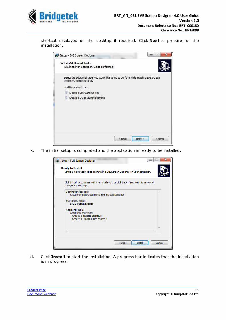
ix. In the Select Additional Tasks window, check “Create a desktop / Create
Quick Launch shortcut” boxes, to have the ESD 4.0 icon and Quick Launch
BRT_AN_021 EVE Screen Designer 4.0 User Guide Version 1.0 Document Reference No.: BRT_000180
Clearance No.: BRT#098
Product Page 16
Document Feedback Copyright © Bridgetek Pte Ltd
shortcut displayed on the desktop if required. Click Next to prepare for the
installation.
x. The initial setup is completed and the application is ready to be installed.
xi. Click Install to start the installation. A progress bar indicates that the installation
is in progress.

BRT_AN_021 EVE Screen Designer 4.0 User Guide Version 1.0 Document Reference No.: BRT_000180
Clearance No.: BRT#098
Product Page 17
Document Feedback Copyright © Bridgetek Pte Ltd
xii. Upon successful installation, click Finish. The ESD 4.0 application UI is displayed.
BRT_AN_021 EVE Screen Designer 4.0 User Guide Version 1.0 Document Reference No.: BRT_000180
Clearance No.: BRT#098
Product Page 18
Document Feedback Copyright © Bridgetek Pte Ltd
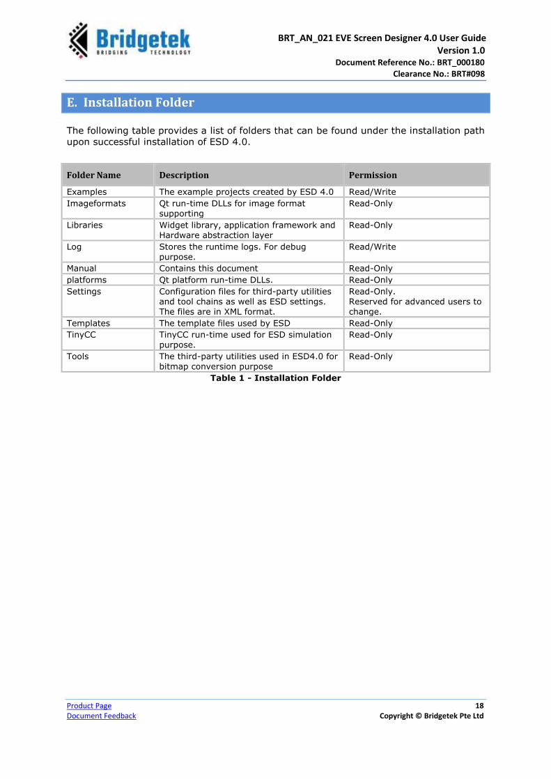
E. Installation Folder
The following table provides a list of folders that can be found under the installation path
upon successful installation of ESD 4.0.
Folder Name Description Permission
Examples The example projects created by ESD 4.0 Read/Write
Imageformats Qt run-time DLLs for image format supporting
Read-Only
Libraries Widget library, application framework and Hardware abstraction layer
Read-Only
Log Stores the runtime logs. For debug purpose.
Read/Write
Manual Contains this document Read-Only
platforms Qt platform run-time DLLs. Read-Only
Settings Configuration files for third-party utilities and tool chains as well as ESD settings. The files are in XML format.
Read-Only. Reserved for advanced users to change.
Templates The template files used by ESD Read-Only
TinyCC TinyCC run-time used for ESD simulation purpose.
Read-Only
Tools The third-party utilities used in ESD4.0 for bitmap conversion purpose
Read-Only
Table 1 - Installation Folder

BRT_AN_021 EVE Screen Designer 4.0 User Guide Version 1.0 Document Reference No.: BRT_000180
Clearance No.: BRT#098
Product Page 19
Document Feedback Copyright © Bridgetek Pte Ltd
IV Working with ESD 4.0
The targeted audience of this chapter are mainly the existing ESD users. This chapter
may help the existing users to get familiar with the new features of ESD 4.0.
A. What’s new in ESD 4.0?
Widget model
ESD 4.0 introduces a standard widget model, which applies to page, layout and widget.
It provides a generic interface for these 3 kinds of nodes. With this feature, users can
manage pages, widgets, and layouts in the same way. With widget model, the widget
hierarchy is estimated. A child widget is managed by its parent widget. Typically, the
following properties of a child widget are decided by its parent widget:
X, Y coordinate
Width, Height
Depth sort property, which determines the rendering sequence of widgets, i.e.
Z order
Allocation mode, when the child widget is allocated/de-allocated.
This provides a different user experience from ESD 3.0. When a user decides to drag a
widget into the screen, it is better to select a parent widget for it. The picture below
illustrates the widget hierarchy in ESD 4.0:
Figure 2 - ESD 4.0 Nodes Hierarchy

BRT_AN_021 EVE Screen Designer 4.0 User Guide Version 1.0 Document Reference No.: BRT_000180
Clearance No.: BRT#098
Product Page 20
Document Feedback Copyright © Bridgetek Pte Ltd
By default, a new page is created with a “Fixed
Position” layout node as a root widget. Any other
widgets are expected to be child widget of “Fixed
Position”. It enables all the child widgets to be
placed with a fixed position within the screen.
Users can work with this layout node the same
way as before in ESD3.0.
However, a page is allowed to have multiple
layouts to manage different zone of the screen.
To adjust the widget hierarchy, users can drag
and drop the widget through “Project
Browser”. Here is an example:
The “Drag” and “Drop” action above will bring the following effect:
1. Widget object “PushButton1” is removed from its parent widget “VerticalLayout”
2. The widget “Stretch3” will take over the ownership of widget object
“PushButton1”.
3. “PushButton1”‘s position and dimension will be re-calculated and assigned by
“Stretch3” widget.
Layout Feature
Based on the generic widget model, ESD 4.0 is able to support the layout feature by
introducing a set of layout widgets and the relevant utility functions into built-in library.
Users can make use of the layout widgets to manage the widgets and pages. The layout
widget normally has no appearance when rendering and it works like a container of
widgets.
For instance, when a label widget is added into a “linear layout” widget, its position and
size is determined by a “linear layout” widget in order to place other widgets of “linear
layout” widget with horizontally or vertically aligned style.
Project Extension Name (*.esd)
Upon installing ESD 4.0, the previous project file extension name “.esd3” will become
obsolete and the new project extension name “.esd” will be enforced. Thus, all the
projects will have the “.esd” extension name.

BRT_AN_021 EVE Screen Designer 4.0 User Guide Version 1.0 Document Reference No.: BRT_000180
Clearance No.: BRT#098
Product Page 21
Document Feedback Copyright © Bridgetek Pte Ltd
Depth Sort Property
In ESD4.0, the depth sort value of widgets serves multiple purposes.
Depth Sort as rendering order
Similar to ESD 3.0, the depth sort still
serves as a rendering order in ESD4.0 if
the parent widget is a fixed positioning
layout, a fill layout, a stretch layout, a
scroll layout, a page or a widget. The
owner widget that has the larger integer
of the depth sort value will promote the
widget to be rendered on top of the
other widgets which have relatively
lower values within the same
layout/widget. In this case, the depth
sort value is equivalent to z-axis value in
3-D context. However, this does not
apply when its parent layout is a linear layout or a switch page layout. The sample
picture demonstrates how a clock widget and a spin box widget are rendered in a page
when the clock widget has higher depth sort value.
User can right click on the widget from the screen layout
designer and use the context menu to adjust the depth sort
as z-order value in design time.
Bring to Top: The selected widget’s depth sort =
max(all widgets’ depth sort) + 1. This sets the selected
widget on top of all other widgets.
Bring Upward: The selected widget’s depth sort =
max(the next higher depth sort from all widgets, its
current depth sort) + 1. This increases the selected
widget’s depth sort on top of the next higher value.
Send Downward: The selected widget’s depth sort = min(the next lower depth sort
from all widgets, its current depth sort) – 1. This decreases the selected widget’s
depth sort below the next lower value.
Send to Bottom: The selected widget’s depth sort = min(all widgets’ depth sort) –
1. This sets the selected widget below all the other widgets.
All widgets are referring to the sibling widgets within the same hierarchy. In other words, they are within the same widget container such as the same layout, same page or the same widget.

BRT_AN_021 EVE Screen Designer 4.0 User Guide Version 1.0 Document Reference No.: BRT_000180
Clearance No.: BRT#098
Product Page 22
Document Feedback Copyright © Bridgetek Pte Ltd
Depth Sort as layout sequencing control
When the parent widget is a
linear layout, the depth sort
value serves as layout
sequencing control. In the case
of within a horizontal linear
layout, the depth sort value
serves as horizontal ordering
along the x-axis. The depth sort with a higher value will be rendered first in the linear
layout. Such that, the widget with the highest depth sort value will be placed at the left
most in the horizontal layout; similarly, the widget with the highest depth sort value will
be placed at the top most in the vertical layout. Refer to Linear Layout for more details.
User can right click on the widget from the screen layout designer,
uses the context menu to adjust the depth sort as x-order/y-order
value in design time.
Bring to Top: The selected widget’s depth sort = max(all
widgets’ depth sort) + 1. This moves the selected widget to the
left most in horizontal linear layout; it moves the selected widget
to the top most in vertical linear layout;
Bring Upward: The selected widget’s depth sort = max(the next higher depth sort
from all widgets, its current depth sort) + 1. This moves the selected widget to one
step to the left in horizontal layout or one step to the top in vertical layout.
Send Downward: The selected widget’s depth sort = min(the next lower depth sort
from all widgets, its current depth sort) – 1. This moves the selected widget to one
step to the right in horizontal layout or one step to the bottom in vertical layout.
Send to Bottom: The selected widget’s depth sort = min(all widgets’ depth sort) –
1. This moves the selected widget to the right most in horizontal linear layout; it
moves the selected widget to the bottom most in vertical linear layout;
All widgets are referring to the sibling widgets within the same hierarchy. In other words, they are within the same widget container such as the same layout, same page or the same widget.
Depth Sort as page sequencing in “Switch Page”
When the parent widget is a switch page widget, the depth sort value serves as page
indexing in switch page container. Changing the depth sort value of the pages will only
affect the index of the pages in the switch page container. The page with the highest
index value will be listed first. However, if all the pages in the container are active, then
the last page will be shown and the rest of pages will be hidden or closed based on the
allocation setting. Users can right click on the widget from the screen layout designer
and use the context menu to adjust the page indexing in design time. Users can only see
the index from project browser. Please refer to Switch Page for further details.

BRT_AN_021 EVE Screen Designer 4.0 User Guide Version 1.0 Document Reference No.: BRT_000180
Clearance No.: BRT#098
Product Page 23
Document Feedback Copyright © Bridgetek Pte Ltd
B. Impacts of ESD 4.0 Updated Features
Since the new/updated features of ESD 4.0 may cause API changes, the existing ESD 3.0
project is not fully compatible with ESD 4.0. Although ESD 4.0 has the utility inside to
detect and migrate opening ESD3.0 project, it may still fail working as expected.
ESD Layouts: A new category of widgets “ESD Layout” are introduced into the Library
Browser, which enables the layout feature.
ESD Widgets: A new set of widgets are introduced into “ESD Widgets” category in the
library. These set widgets are to be used in constructing the pages. The nodes under
the “ESD Render Functions” are not supposed to construct page as it has no widget
interface and the layout widget is unable to manage them.
ESD Sketch
ESD Numeric Label
ESD Fixed Point Label
ESD Scroll Image
ESD Image
ESD Scroll Panel
C. Migrating from ESD 3.0 to ESD 4.0 project
When ESD 4.0 opens an existing ESD 3.0 project, it will prompt users to migrate it. If
user chooses not to migrate, ESD 4.0 will not open ESD3.0 project.
MIGRATION NOTES
1. Please back up your project if you are not sure about the migration. The migration
process will overwrite the project and it cannot be reversed.
2. The migrated project file will be renamed from “*.esd3” to “*.esd”.
3. The target module of the opened project will be redirected to two built-in platforms
after migration. So if the target module is in 320 x 480 resolutions, users may select
the platform “ME810A HV35R” from “Build Target” combo box from the toolbar and
make a platform switch.
In some cases, if an existing ESD 3.0 project cannot be migrated to ESD 3.0, then users
are required to migrate manually.
The variable “Parent” of logic is renamed to “Owner” in ESD 4.0.
X, Y, Width, Height properties in widgets is now accessible through the widget
variable.
Instead of pointer, struct “Ft_Esd_BitmapCell” shall be used by value in ESD 4.0.

BRT_AN_021 EVE Screen Designer 4.0 User Guide Version 1.0 Document Reference No.: BRT_000180
Clearance No.: BRT#098
Product Page 24
Document Feedback Copyright © Bridgetek Pte Ltd
In order to restore the default behaviour of application
logic “App.main”, users may need to manually move
the existing pages into layout widget “Switch Page” in
the Project Browser.
D. Setting Platform Specific Properties
In ESD 4.0, users are able to create one project supporting multiple platforms with
various screen size. Therefore, at different platform, the same widget may have
different property value. For instance, for a platform with screen size 480 x 320, the
button size may shrink to a smaller size from the original value for a platform with
screen size 800 x 480.
Users can make a property value specific to the current target through the context menu
of the property browser. It can be done by right clicking the selected property of the
current widget. This is illustrated in the picture given below.
Figure 3 - Making Value Specific to Current Target
User can remove value specific to current target through context menu in property
browser by right clicking the selected property of current widget. This is illustrated in the
picture given below.

BRT_AN_021 EVE Screen Designer 4.0 User Guide Version 1.0 Document Reference No.: BRT_000180
Clearance No.: BRT#098
Product Page 25
Document Feedback Copyright © Bridgetek Pte Ltd
Figure 4 - Removing Target Specific Value
Users can refer to the “ScreenResolution” project under the “Installation\Example”
folder.

BRT_AN_021 EVE Screen Designer 4.0 User Guide Version 1.0 Document Reference No.: BRT_000180
Clearance No.: BRT#098
Product Page 26
Document Feedback Copyright © Bridgetek Pte Ltd
V Getting Started
A. The Graphical User Interface
ESD 4.0 user interface has the following components:
1 Menu Bar
2 Toolbar
3 Project Explorer
4 Screen Layout Editor
5 Logic Node Editor
6 Library Browser
7 Error List/Inspector
8 Output window
9 Property Editor
10 Status Bar
Figure 5 - EVE Screen Designer 4.0 User Interface Components
1
2
3 4
5 6
7
8 9
10
BRT_AN_021 EVE Screen Designer 4.0 User Guide Version 1.0 Document Reference No.: BRT_000180
Clearance No.: BRT#098
Product Page 27
Document Feedback Copyright © Bridgetek Pte Ltd
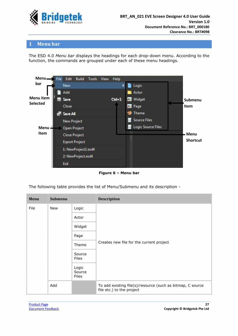
1 Menu bar
The ESD 4.0 Menu bar displays the headings for each drop-down menu. According to the
function, the commands are grouped under each of these menu headings.
Figure 6 – Menu bar
The following table provides the list of Menu/Submenu and its description -
Menu Submenu Description
File New Logic
Creates new file for the current project
Actor
Widget
Page
Theme
Source Files
Logic Source Files
Add To add existing file(s)/resource (such as bitmap, C source file etc.) to the project
Menu
Shortcut
Submenu
Item
Menu item Selected
Menu bar
Menu Item
BRT_AN_021 EVE Screen Designer 4.0 User Guide Version 1.0 Document Reference No.: BRT_000180
Clearance No.: BRT#098
Product Page 28
Document Feedback Copyright © Bridgetek Pte Ltd
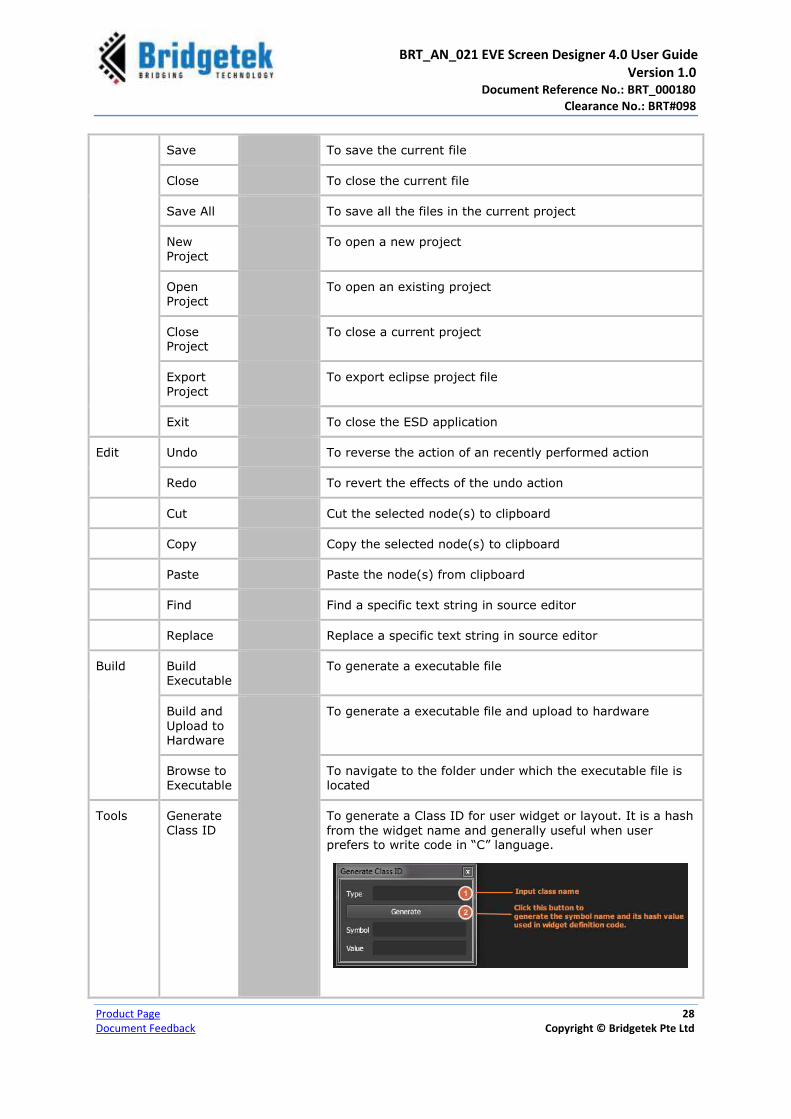
Save To save the current file
Close To close the current file
Save All To save all the files in the current project
New Project
To open a new project
Open Project
To open an existing project
Close Project
To close a current project
Export Project
To export eclipse project file
Exit To close the ESD application
Edit Undo To reverse the action of an recently performed action
Redo To revert the effects of the undo action
Cut Cut the selected node(s) to clipboard
Copy Copy the selected node(s) to clipboard
Paste Paste the node(s) from clipboard
Find Find a specific text string in source editor
Replace Replace a specific text string in source editor
Build Build Executable
To generate a executable file
Build and
Upload to Hardware
To generate a executable file and upload to hardware
Browse to Executable
To navigate to the folder under which the executable file is located
Tools Generate Class ID
To generate a Class ID for user widget or layout. It is a hash
from the widget name and generally useful when user prefers to write code in “C” language.

BRT_AN_021 EVE Screen Designer 4.0 User Guide Version 1.0 Document Reference No.: BRT_000180
Clearance No.: BRT#098
Product Page 29
Document Feedback Copyright © Bridgetek Pte Ltd
View Project
To display or hide a component view. By default all the components are displayed.
Library
Properties
Inspector
Error List
Output
Help User Guide
Opens the ESD 4.0 User Guide
About Displays the version details
3rd Party Displays the copyright, disclaimer and license information of the 3rd party software
Table 2 - Menu & Description
2 Toolbar
The Toolbar provides an easy access to common functions (in the form of icons) such as
new file, save file, undo, redo etc.
Figure 7 - Toolbar
The following table provides the list of toolbar functions and its description –
Toolbar Function Description
New To open new Logic/Actor/Widget/Page/Theme/Source Files/Logic Source Files
Add To add existing resource (such as bitmap, C source file etc.) to the project
Save To save the currently open file
Save All To save all the files in the current project
Undo To reverse the action of a recently performed action
New
Add
Save
Save All
Undo
Redo
Simulation
Restart
Recompile
Build Executable
Build Target
Toolchain
Build & Upload to Hardware
Programmer

BRT_AN_021 EVE Screen Designer 4.0 User Guide Version 1.0 Document Reference No.: BRT_000180
Clearance No.: BRT#098
Product Page 30
Document Feedback Copyright © Bridgetek Pte Ltd
Redo To revert the effects of the undo action
Simulation A toggle button which starts or stops the simulation mode.
- This state indicates that the ESD 4.0is in simulation mode. Clicking
this button stops the simulation.
- This state indicates that the ESD 4.0is out of simulation mode.
Users can drag/drop widgets or edit them safely.
Restart To automatically restart the EVE emulator. Clicking this button will force the simulated screens to be re-drawn.
Recompile To recompile the whole project’s source code using ESD built-in TinyCC compiler. It is a mandatory procedure for simulation.
Build Executable To build the project and generate the executable file
Build Target Select the hardware platform as source code building target
Toolchain Select the building configuration when tool chain is invoked to build
Build and Upload to Hardware
To build the project; generate executable file and upload it into the selected hardware (e.g. MM900EV2A)
Programmer Defaults to FT900 One-Wire programmer.
Table 3 - Toolbar & Description
3 Project Explorer
The Project Explorer window organizes all the files used in
the project in a tree view. It also lists out all the
resources used by each file. Project explorer allows users
to navigate each page of the project.
Figure 8 - Project Explorer window

BRT_AN_021 EVE Screen Designer 4.0 User Guide Version 1.0 Document Reference No.: BRT_000180
Clearance No.: BRT#098
Product Page 31
Document Feedback Copyright © Bridgetek Pte Ltd
4 Screen Layout Editor
The Screen Layout Editor displays the rendering output of EVE and allows users to edit C
source code. The page/widget/main files can be opened and edited in this editor.
Figure 9 - Screen Layout Editor – App.main
Figure 10 - Screen Layout Editor - MainPage.c (C Source Code)
It shares one view port with the logic node editor. Users can adjust the size of the screen
layout editor by dragging the splitter handle.
Users can drag and drop the widgets from the library browser to form the layout when
simulation mode is “off”. For the other kind of logic nodes, if the EVE rendering process
not defined, screen layout editor does not allow them to be dropped in.

BRT_AN_021 EVE Screen Designer 4.0 User Guide Version 1.0 Document Reference No.: BRT_000180
Clearance No.: BRT#098
Product Page 32
Document Feedback Copyright © Bridgetek Pte Ltd
5 Logic Node Editor
The Logic Note Editor allows users to layout logic nodes and to establish connections to
create logic maps. Users can drag and drop a logic node from the Library Browser
component to the Logic Note Editor in order to create connections.
Figure 11 - Logic Node Editor
6 Library Browser
The Library Browser allows storing all the available logic nodes and
resources in ESD 4.0 that includes both built-in and user-defined
ones. Users can view these logic nodes by category and select one
for their project.
Figure 12 - Library Browser
BRT_AN_021 EVE Screen Designer 4.0 User Guide Version 1.0 Document Reference No.: BRT_000180
Clearance No.: BRT#098
Product Page 33
Document Feedback Copyright © Bridgetek Pte Ltd
The following table provides the ESD library name and its description –
Library Name Description
ESD Layouts ESD built-in layout widgets and relevant utilities
ESD Render Functions ESD built-in Render functions
ESD Theme ESD built-in basic theme manipulation functions
ESD Utilities ESD built-in utilities
ESD Widgets ESD built-in widgets
Logic Flow ESD built-in logic node for control flow
Logic Interface ESD built-in logic node for interface
User Actors User defined actor logic node. It is empty by default.
User Functions User defined functions. It is empty by default.
User Layouts User defined layouts. It is empty by default.
User Logic User defined logics. It is empty by default.
User Pages Pages added by user. It is empty by default if no page is created.
User Resources Resources added by users (For example: bitmap). It is empty by default.
User Widgets Widgets created and added by users. It is empty by default.
Table 4 - ESD 4.0 Libraries
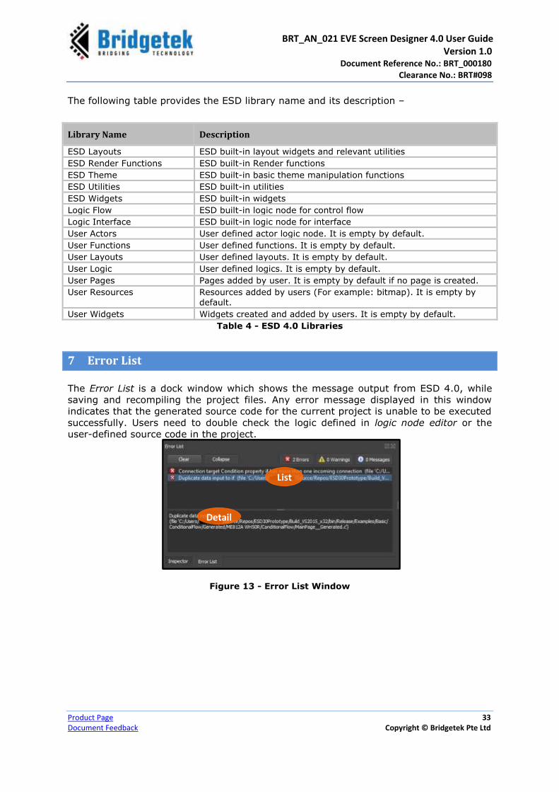
7 Error List
The Error List is a dock window which shows the message output from ESD 4.0, while
saving and recompiling the project files. Any error message displayed in this window
indicates that the generated source code for the current project is unable to be executed
successfully. Users need to double check the logic defined in logic node editor or the
user-defined source code in the project.
Figure 13 - Error List Window
List
Detail

BRT_AN_021 EVE Screen Designer 4.0 User Guide Version 1.0 Document Reference No.: BRT_000180
Clearance No.: BRT#098
Product Page 34
Document Feedback Copyright © Bridgetek Pte Ltd
8 Output
The Output component is a docked window which shows the message output from the
EVE emulator and Toolchain.
Figure 14 - Output Window
To check a message from the EVE emulator, click “Simulation” from the drop down list.
To check a message from the EVE Toolchain while building generated source code, click
“Build” from the drop down list. This window is automatically updated during simulation
or building.
9 Property Editor
The Property Editor allows user to edit the properties of selected logic nodes. The sample
screenshot given below shows the property editor of an ESD Push button.
Figure 15 - Property Editor (ESD Push Button)

BRT_AN_021 EVE Screen Designer 4.0 User Guide Version 1.0 Document Reference No.: BRT_000180
Clearance No.: BRT#098
Product Page 35
Document Feedback Copyright © Bridgetek Pte Ltd
10 Status bar
The Status bar is found at the bottom of the user interface. It primarily displays the
current status of any of process or job that is being handled by the application. For
example, if the user is performing a C compilation, then the compilation status of the
generated C code is displayed.
Figure 16 - Status bar
The percentage of bitmap handles used by the current page
The percentage of RAM_G memory used by the current page
The compilation status of the generated “C” code. Project cannot be simulated if the compilation fails.
Simulation status (whether in progress or not)

BRT_AN_021 EVE Screen Designer 4.0 User Guide Version 1.0 Document Reference No.: BRT_000180
Clearance No.: BRT#098
Product Page 36
Document Feedback Copyright © Bridgetek Pte Ltd
B. Application Project Structure
An Application consists of one or more pages. Each page in turn may contain one or
more widgets. Widgets and pages are connected via connection lines so that the screen
logic is defined.
The application model follows a strict hierarchical structure where all the pages are
owned and managed by the application, and all the widgets are owned by their
respective pages. The visibility and memory lifetime of the widgets are thus managed on
a page-by-page basis.
By design, all widgets and pages are generated to be entirely modular and self-sufficient.
Any interaction between the widgets and pages is therefore required to be routed
through the hierarchical chain. (Only node connections exist between the directly
connected nodes in the hierarchy.)
Figure 17 - Application Project Structure
File Name Description
*.esd Project file - This XML file describes what files are included in this project. This file is unique for the whole project.
*.main Logic file - This XML file describes the application level logic. By default, it is
named as “App.main” and is unique project wide.
*.page Page Node Definition file - This XML file describes what widgets are contained and connected in each page. By default: “AppScreen.Page” is added, where a switch
page may be included for control on page transition. A page can contain other pages, but switch page is required for page transition control.
*.widget Widget Node Definition file. This XML file describes a widget detail.
A widget can contain other nodes, which may include widget node, actor node and logic node.
*.actor Actor Node Definition file. This XML file describes the actor node detail.
AppScreen.Page
S W
App.main
Page Page Page
W W W W W W W W W
Application
Page
Switch Page
Widget
S
W
BRT_AN_021 EVE Screen Designer 4.0 User Guide Version 1.0 Document Reference No.: BRT_000180
Clearance No.: BRT#098
Product Page 37
Document Feedback Copyright © Bridgetek Pte Ltd
*.logic Logic Object Definition file. This XML file describes the logic node details.
*.theme Application Theme Definition file. This XML file describes a theme detail.
*.h C language source header file
*.c C language source body file
*.png, *.jpg, *.jpeg
Image resource files
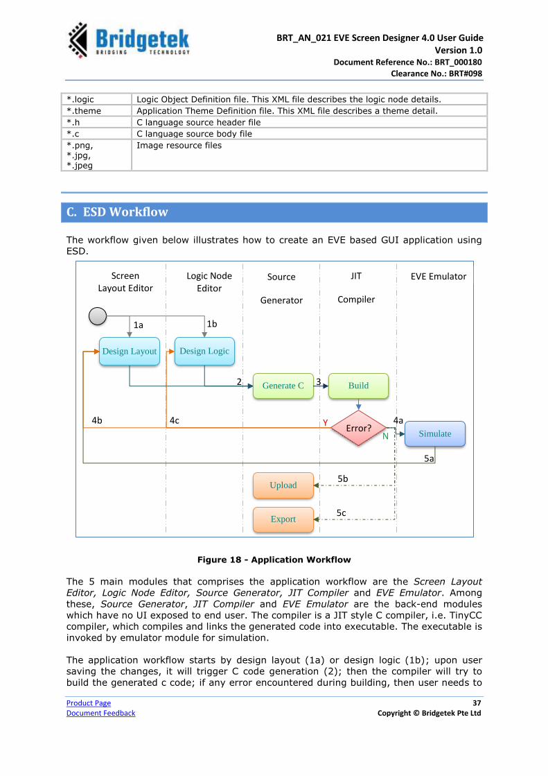
C. ESD Workflow
The workflow given below illustrates how to create an EVE based GUI application using
ESD.
Figure 18 - Application Workflow
The 5 main modules that comprises the application workflow are the Screen Layout
Editor, Logic Node Editor, Source Generator, JIT Compiler and EVE Emulator. Among
these, Source Generator, JIT Compiler and EVE Emulator are the back-end modules
which have no UI exposed to end user. The compiler is a JIT style C compiler, i.e. TinyCC
compiler, which compiles and links the generated code into executable. The executable is
invoked by emulator module for simulation.
The application workflow starts by design layout (1a) or design logic (1b); upon user
saving the changes, it will trigger C code generation (2); then the compiler will try to
build the generated c code; if any error encountered during building, then user needs to
Logic Node Editor
Design Layout Design Logic
Simulate
Build
Upload
Export
Screen Layout Editor
Source
Generator
JIT
Compiler
EVE Emulator
Generate C
1a 1b
2 3
4a
5b
5a
5c
4b 4c Error?
Y
N
BRT_AN_021 EVE Screen Designer 4.0 User Guide Version 1.0 Document Reference No.: BRT_000180
Clearance No.: BRT#098
Product Page 38
Document Feedback Copyright © Bridgetek Pte Ltd
continue on design layout (4b) or design logic (4c); or if no error found, then the
emulator will start simulating (4a) the project. Users will be able to upload (5b) the
binary to the EVE chips or export (5c) the project as eclipse C project.
Design Layout using Layout Editor
Users need to determine how many pages are included in the project and what widgets
are to be contained in each page. After a page is created, users can drag and drop the
widgets to design the appearance of the page in the screen layout editor. This process
determines how many screens are shown in the project and how they look like together.
Custom Widget
ESD 4.0 provides a set of built-in widgets for users to construct screen layouts.
Additionally, if the built-in widgets do not meet the design requirement, users may
define and design custom widgets.
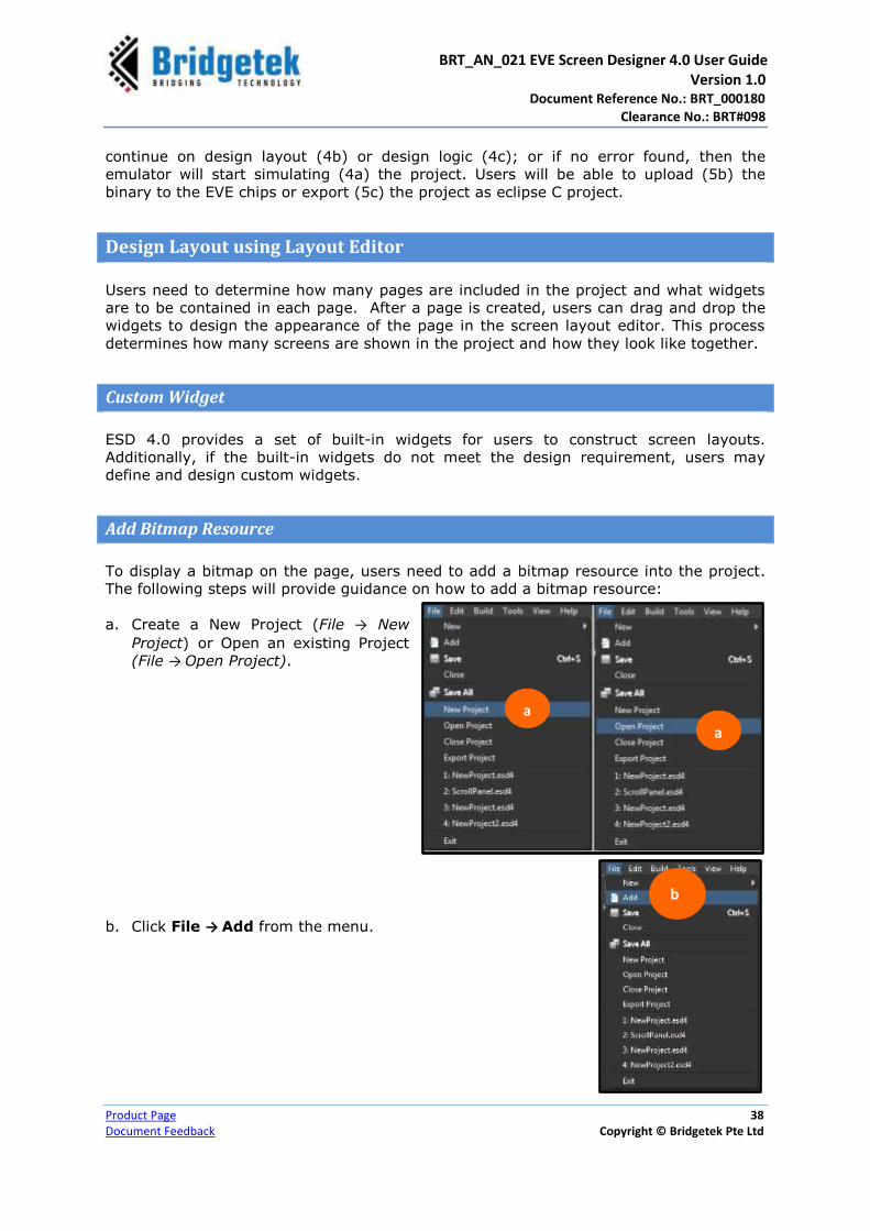
Add Bitmap Resource
To display a bitmap on the page, users need to add a bitmap resource into the project.
The following steps will provide guidance on how to add a bitmap resource:
a. Create a New Project (File → New
Project) or Open an existing Project
(File → Open Project).
b. Click File → Add from the menu.
a
a
b
BRT_AN_021 EVE Screen Designer 4.0 User Guide Version 1.0 Document Reference No.: BRT_000180
Clearance No.: BRT#098
Product Page 39
Document Feedback Copyright © Bridgetek Pte Ltd
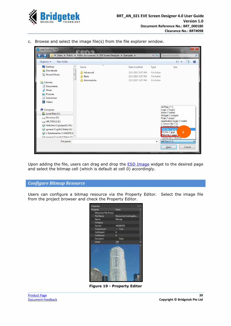
c. Browse and select the image file(s) from the file explorer window.
Upon adding the file, users can drag and drop the ESD Image widget to the desired page
and select the bitmap cell (which is default at cell 0) accordingly.
Configure Bitmap Resource
Users can configure a bitmap resource via the Property Editor. Select the image file
from the project browser and check the Property Editor.
Figure 19 - Property Editor
c

BRT_AN_021 EVE Screen Designer 4.0 User Guide Version 1.0 Document Reference No.: BRT_000180
Clearance No.: BRT#098
Product Page 40
Document Feedback Copyright © Bridgetek Pte Ltd
Property Value/Description
File Name Name of the image file
Name Resource Type Name. In this case, the selected resource type is Bitmap.
Category Category of the selected object
Format Image Format – The target format of bitmap can be –
L1/L2/L4/L8
RGB332/RGB565 ARGB1555/ARGB2/ARGB4 PALETTED4444/PALETTED565/PALETTED8 DXT1 JPEG (decompressed into RGB565 format only) PNG (decompressed into RGB565 format only)
Compressed Set bitmap compression on/off
CellHeight The pixel number of one cell. For example, if the bitmap width is 240 and height is 240, then it can be defined as two cells with “CellHeight” - 120 or four cells with “CellHeight” – 60. Cell Height default at 0 which mean there will be only one cell no matter how large the bitmap it is.
CellNames This field will enable system to create a list of n number of user defined cell names instead system generated which is suffixed with “_x”.
Persistent Keeps the memory persistent even if the bitmap is not displayed when it is true.
Width The width of bitmap image in pixels
Height The height of bitmap image in pixels
Table 5 - Bitmap Resource Properties
Design Screen Logic using Logic Node Editor
Users can define the dynamic behaviour of an application in this phase. The Logic Node
Editor employs the innovative visual programming idea to help users define logic flows
without coding.
During this phase, users can decide the behaviour mode of both inner- and inter-pages.
For inner-page behaviour, users can connect the widgets on the page via the logic node
editor adding more logic nodes from the library browser, if necessary.
Inter-page logic behaviour is captured in the application logic, which is normally named
as “AppScreen.page”. Users are required to drag and drop the predefined pages into the
logic node editor and connect these pages via the logic interface. This will define the
inter-pages behaviour like screen logic.

BRT_AN_021 EVE Screen Designer 4.0 User Guide Version 1.0 Document Reference No.: BRT_000180
Clearance No.: BRT#098
Product Page 41
Document Feedback Copyright © Bridgetek Pte Ltd
Simulate
To validate the behaviour of the screen logic, users may need to simulate the project on
the PC before compiling and downloading the generated C code into the target device.
When application logic is selected, users can simulate the whole project by clicking the
“Simulation” button on the toolbar. When the application is in simulation mode, users
cannot drag and drop the widgets into the layout editor. The PC mouse will act as a
touch stylus on the touch panel to interact with application directly.
Before performing a simulation, it is strongly recommended to save the current project
by clicking the “Save all” button. Once the simulation is completed, ensure to switch off
the simulation mode by clicking the “Simulation” button again.
Simulation State Description
ON State - Indicates that the simulation is in progress. Clicking on it will switch off the simulation. In this state, users will not be able to edit the page or project.
OFF State - Indicates that currently simulation is not in progress. Clicking on it will switch on the simulation.
Build & Upload
Upon installing the FT90x Toolchain, the application will invoke its compiler and
programmer so that the current project can be built and uploaded successfully into the
target hardware.
Click on the “Build Target” button to build a
project
Click on the “Build and Upload to Hardware”
button to build the program and upload it to the
target device
Export
Upon completing the screen design, it’s time to move the project to the next phase of
the workflow – “Export Project”. This function is used to prepare all the necessary files
for the MCU tool chain so that users can make further enhancements such as connecting
sensors or external hardware to a full HMI solution.
Once the export is completed, the application copies all the generated “C” source code
and necessary bitmap resources into a user defined folder. In addition, the eclipse
project file “.cproject” and “.project” files are also generated so that the users can open
the project in the FT90X eclipse IDE 4 . All the generated files are named as
“*_generated.c”.
4 http://brtchip.com/ft9xx-toolchain/

BRT_AN_021 EVE Screen Designer 4.0 User Guide Version 1.0 Document Reference No.: BRT_000180
Clearance No.: BRT#098
Product Page 42
Document Feedback Copyright © Bridgetek Pte Ltd
Exported Folder Structure
The following table provides the list folders and files that are created upon exporting the
project –
Folder / Files Description
.cproject Eclipse project file
.project Eclipse project file
FT_Esd_Framework Contains the application framework files.
It is recommended not to make any changes to this folder/ files
FT_Esd_Widgets Contains the widget files
It is recommended not to make any changes to this folder/ files
FT_Esd_Hal Contains the hardware abstraction layer files. These files may be changed to support a different MCU.
Data Contains the converted bitmap resource data which is used by the current project
$(ProjectName) Contains the application specific source code
Bitmap Resource
If a bitmap resource is used in the project, users are required to download the converted
bitmap resource into an SD card root directory and insert the SD card into the hardware
module.
The converted bitmap resource is located at:
$(ProjectFolder)\build\$(PlatformName)\data
Or
$(ExportFolder)\data
The bitmap resource file with .bin extension is called to decompress using the EVE
engine command CMD_INFLATE.
As per the Hardware Platform requirements, the SD card must be formatted as a FAT32
file system.

BRT_AN_021 EVE Screen Designer 4.0 User Guide Version 1.0 Document Reference No.: BRT_000180
Clearance No.: BRT#098
Product Page 43
Document Feedback Copyright © Bridgetek Pte Ltd
D. Layout Editor
The Layout Editor allows users to preview a single page as well as the whole project.
ESD employs the EVE emulator to render an EVE display onto the layout editor. It
provides users the interface to view the result of the screen design and its logic.
The following file types are displayed in ESD layout editor:
Application logic file - generally with “.main” extension
Page file - generally with “.page” extension
Page File
Page stands for a single screen which will be rendered. One application consists of at
least one page. Page may have its own life cycle and manages all the widgets on it. Only
widgets can be dragged and dropped into pages at Page layout editor. However, all the
nodes from a library can be dragged and dropped into the logic node editor.
“Active” Property
The “Active” property is a Boolean value to control the page, and is created or released
while the application is updating the pages. By default, the “Active” property is true. The
page is created and shown, unless “Switch” end is connected.
Switch Page
Users can define multiple pages within the
project. “Switch Page” ESD layout should add to
manage the pages. User can drag and drop the
pages into this switch page from project browser.
The picture below displays how the logic editor
view looks like for the switch page logic.
Figure 20 – Switch Page
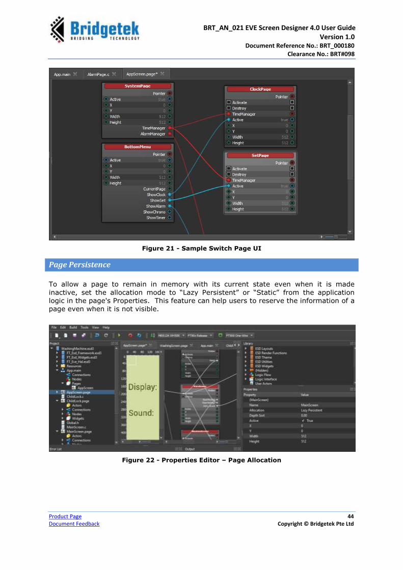
BRT_AN_021 EVE Screen Designer 4.0 User Guide Version 1.0 Document Reference No.: BRT_000180
Clearance No.: BRT#098
Product Page 44
Document Feedback Copyright © Bridgetek Pte Ltd
Figure 21 - Sample Switch Page UI
Page Persistence
To allow a page to remain in memory with its current state even when it is made
inactive, set the allocation mode to “Lazy Persistent” or “Static” from the application
logic in the page's Properties. This feature can help users to reserve the information of a
page even when it is not visible.
Figure 22 - Properties Editor – Page Allocation

BRT_AN_021 EVE Screen Designer 4.0 User Guide Version 1.0 Document Reference No.: BRT_000180
Clearance No.: BRT#098
Product Page 45
Document Feedback Copyright © Bridgetek Pte Ltd
The page allocation modes supported in ESD 4.0 are listed in the table given below:
Allocation Mode Description
Static Page is always persistent in memory after application starts
Lazy Page is created when it is in active state and destroyed when it is inactive
Lazy Persistent Page is created when it is in active state but persistent in memory when it is inactive until application is closed.
User Defined Function for Page File
Users can write their own code to handle the “Pushed” signal of the “ESD Push Button”
widget. Users are required to select the “ESD Push Button” widget in the logic node
editor and double click it. A function will be generated to replace the user defined
function.
ESD_METHOD(MainPage_ESD_Push_Button_Pushed, Context = MainPage)
void MainPage_ESD_Push_Button_Pushed(MainPage *context)
{
// Users can write their code here
}
The code can be located at $(PageFileName).c file.
Figure 23 - Sample Source File
Zoom In & Out
The visual area of the screen layout editor can be zoomed when the current file is a page
file, i.e., “.page” file. The mouse wheel button provides zoom-in and zoom-out
functionality, allowing users to view more details about the screen design. Refer to the
below sample picture.
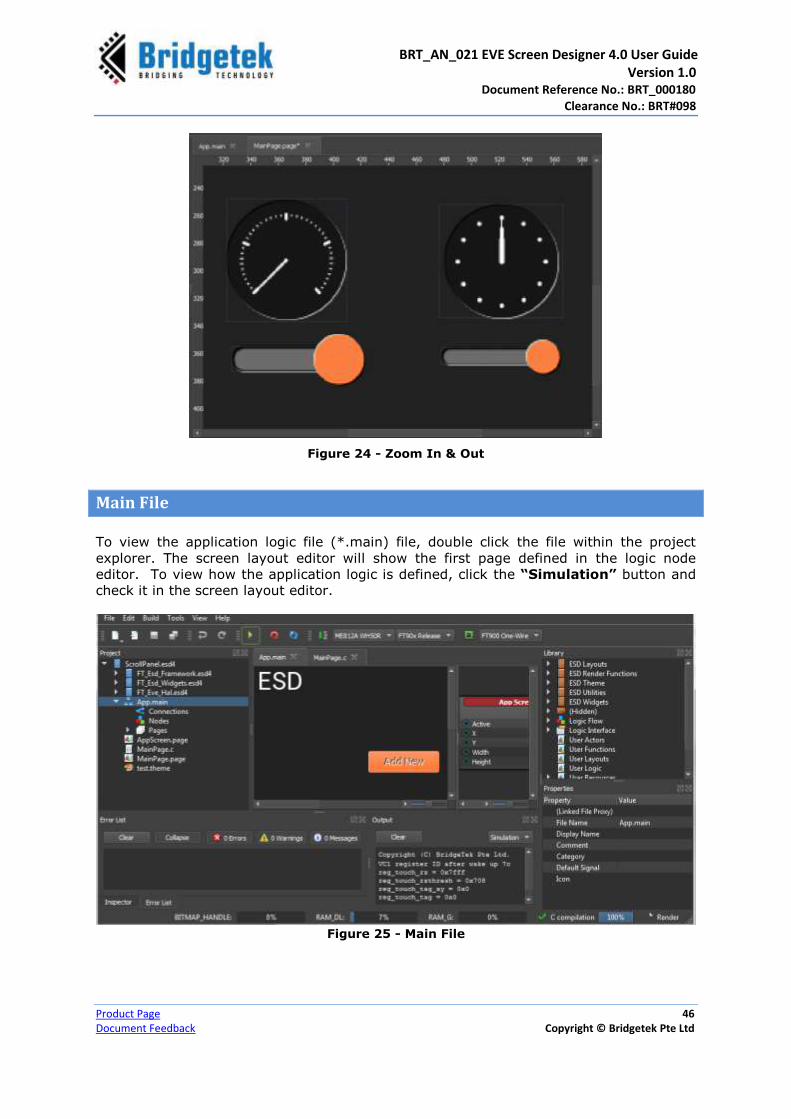
BRT_AN_021 EVE Screen Designer 4.0 User Guide Version 1.0 Document Reference No.: BRT_000180
Clearance No.: BRT#098
Product Page 46
Document Feedback Copyright © Bridgetek Pte Ltd
Figure 24 - Zoom In & Out
Main File
To view the application logic file (*.main) file, double click the file within the project
explorer. The screen layout editor will show the first page defined in the logic node
editor. To view how the application logic is defined, click the “Simulation” button and
check it in the screen layout editor.
Figure 25 - Main File

BRT_AN_021 EVE Screen Designer 4.0 User Guide Version 1.0 Document Reference No.: BRT_000180
Clearance No.: BRT#098
Product Page 47
Document Feedback Copyright © Bridgetek Pte Ltd
Logic File
The logic file contains certain logic that is used to encapsulate the user defined logic. It
works similar to a C function. A logic file does not render any user interface.
Figure 26 – Sample Logic File
C File
The screen layout editor provides a simple C editor when users double click a “.c” file in
the project browser. Note that it is not a full-fledged C editor and many features may be
implemented in the future.
Figure 27 - C File / C Editor
To effect the changes made, ensure that all the changes are saved to the project by clicking “File → Save All” from the menu or from the toolbar.
Simple C Editor
.c file

BRT_AN_021 EVE Screen Designer 4.0 User Guide Version 1.0 Document Reference No.: BRT_000180
Clearance No.: BRT#098
Product Page 48
Document Feedback Copyright © Bridgetek Pte Ltd
E. Logic Note Editor
Using the Logic Node Editor (LNE), users compose screen logic by connecting logic
nodes. The Logic Note Editor is designed to open the following file formats:
Application logic file , *.main file
Screen logic file, *.page file
Widget file, *.widget
Actor file, *.actor
User defined logic file, *.logic file
Basic Logic Node
ESD 4.0 has some built-in predefined basic logic nodes. These basic logic nodes provide
basic control flow and logic interfaces as well as basic functions. A typical basic logic
node is represented in the logic node editor as below, the name of which is shown in
white.
Figure 28 – Logic Node Editor - Basic Logic Node
Within the library browser, the basic logic nodes are located at “Logic Flow”, “Logic
Interface”, “ESD Utilities” and “EVE Render Functions”.
Figure 29 - Library Browser - Basic Logic Nodes
Composite Logic Node
A Composite Logic Node is made up by connecting multiple basic logic nodes. A typical
composite logic node is defined in a standalone document in XML format and is shown in
the logic node (refer to Figure 28).
Basic
Logic
Nodes
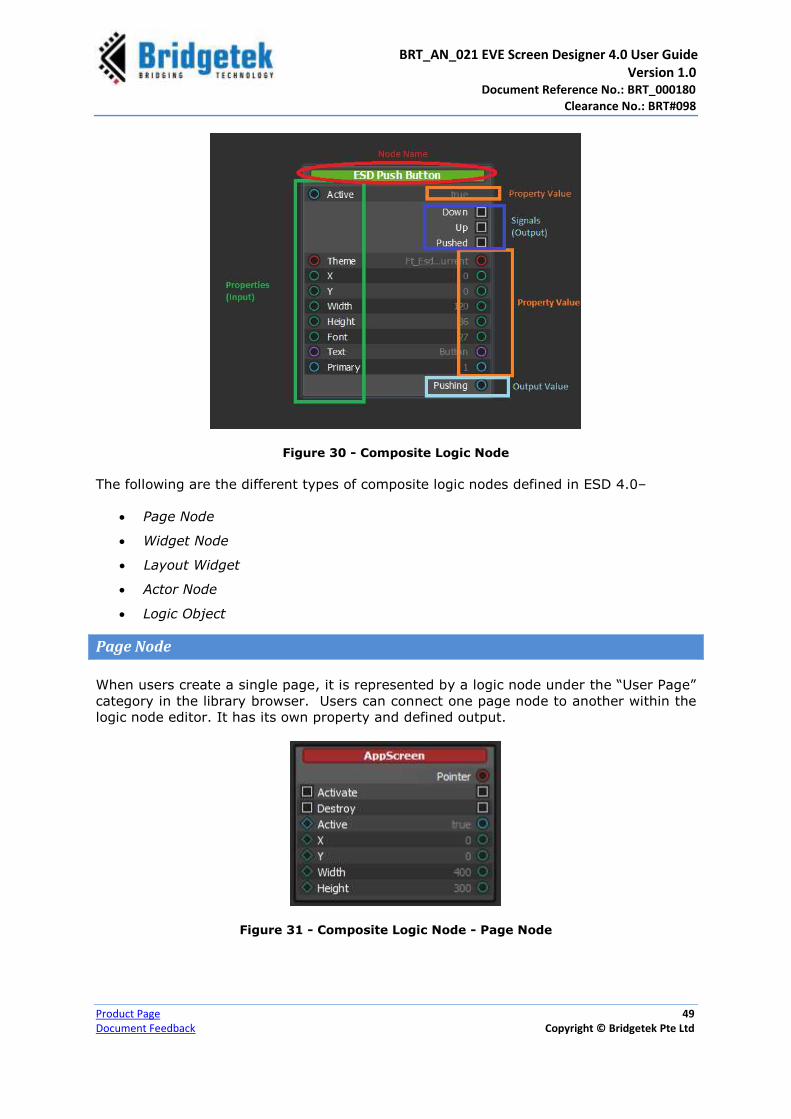
BRT_AN_021 EVE Screen Designer 4.0 User Guide Version 1.0 Document Reference No.: BRT_000180
Clearance No.: BRT#098
Product Page 49
Document Feedback Copyright © Bridgetek Pte Ltd
Figure 30 - Composite Logic Node
The following are the different types of composite logic nodes defined in ESD 4.0–
Page Node
Widget Node
Layout Widget
Actor Node
Logic Object
Page Node
When users create a single page, it is represented by a logic node under the “User Page”
category in the library browser. Users can connect one page node to another within the
logic node editor. It has its own property and defined output.
Figure 31 - Composite Logic Node - Page Node
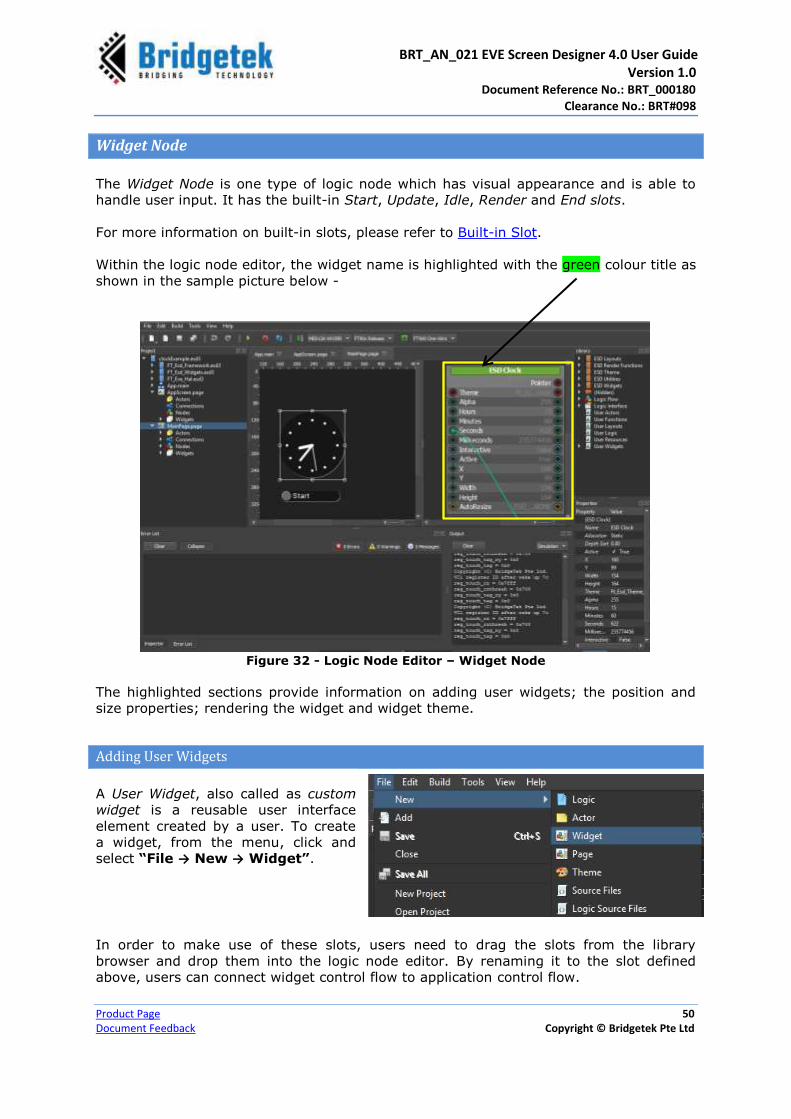
BRT_AN_021 EVE Screen Designer 4.0 User Guide Version 1.0 Document Reference No.: BRT_000180
Clearance No.: BRT#098
Product Page 50
Document Feedback Copyright © Bridgetek Pte Ltd
Widget Node
The Widget Node is one type of logic node which has visual appearance and is able to
handle user input. It has the built-in Start, Update, Idle, Render and End slots.
For more information on built-in slots, please refer to Built-in Slot.
Within the logic node editor, the widget name is highlighted with the green colour title as
shown in the sample picture below -
Figure 32 - Logic Node Editor – Widget Node
The highlighted sections provide information on adding user widgets; the position and
size properties; rendering the widget and widget theme.
Adding User Widgets
A User Widget, also called as custom
widget is a reusable user interface
element created by a user. To create
a widget, from the menu, click and
select “File → New → Widget”.
In order to make use of these slots, users need to drag the slots from the library
browser and drop them into the logic node editor. By renaming it to the slot defined
above, users can connect widget control flow to application control flow.

BRT_AN_021 EVE Screen Designer 4.0 User Guide Version 1.0 Document Reference No.: BRT_000180
Clearance No.: BRT#098
Product Page 51
Document Feedback Copyright © Bridgetek Pte Ltd
Position & Size Properties
As a user interface element, widgets have at least position and size properties so that
users can control them using a visible handle. Position property is defined by an “Input”
node with “ft_int16_t” type named as “X” or “Y”. Size property is defined by an “Input”
node with “ft_int16_t” type named as “Width” or “Height”. A sample picture of the “X”
property is given below –
Figure 33 - User Widget - Position & Size Properties
Rendering a widget
Rendering of a widget may be implemented fully in the logic editor, or directly in the
code using the logic editor to glue together the code with the generated structures. To
create the render function, simply add a Slot from the Logic Interface category of the
library browser, name it “Render” and double click to create the user method for
handling the rendering. The widget is expected to restore any graphics state it changes,
with the exception of the state values specified below.
Preferably use the Ft_Esd_Dl_ utility functions for displaying list drawing when available.
Several state parameters which may be expected to be changed often to the same value
implement de-duplication here to shorten the display list. The de-duplicated values
are: Palette source, Color RGB, Color A, Handle, Cell, and Vertex Format. These graphic
state values are not required to be restored to their original values when the Ft_Esd_Dl_
functions are used. These values should be expected to be any undefined value at the
start of the Rendering function.
Access the value of the X input property as given below:
int x = context->X(context->Owner);
This calls the get()function assigned by the parent to the X property, passing the
owner’s context to the function to handle it there.

BRT_AN_021 EVE Screen Designer 4.0 User Guide Version 1.0 Document Reference No.: BRT_000180
Clearance No.: BRT#098
Product Page 52
Document Feedback Copyright © Bridgetek Pte Ltd
Theme
Widgets should provide property input to override the default application theme. An
input property with type Ft_Esd_Theme * should be added by dragging one input node
from the “Logic Interface” category of the library browser.
Colours from the theme may be accessed from the logic editor using the utility functions
under the ESD Theme category, or from the user code as given below –
Ft_Esd_Theme *theme = context->Theme(context->Owner);
if (theme == NULL) theme = Ft_Esd_Theme_GetCurrent();
ft_rgb32_t primaryColor = theme->PrimaryColor;
Touch Input
In order to handle the touch input, add a Touch Tag node from “ESD Utilities” category
of the library browser to the logic editor, and either handle the signals or access its state
through the Touch Tag interface. Users need to make use of the “Tag” value provided
by the “Touch Tag” node during the Render function, and restore the “Tag” to value 0
after the relevant portion of the rendering.
To handle any of the signals from Touch Tag in user code, simply create an
ESD_METHOD style function in the same format as the Render user code function, and it
will be available from the User Functions category in the library to drag into the logic
editor and connect to any of the signals from the Touch Tag node.
Layout Type Widget
Layout widget is a layout container for widgets. Unlike
widget nodes which have visual appearance, a layout
widget manages the layout specification for its child
widgets. Layout widgets are introduced only in ESD 4.0.
Figure 34 & 35 displays the various layout widgets
supported in ESD 4.0.
Figure 34 - Layout Widgets
Layout
Widgets

BRT_AN_021 EVE Screen Designer 4.0 User Guide Version 1.0 Document Reference No.: BRT_000180
Clearance No.: BRT#098
Product Page 53
Document Feedback Copyright © Bridgetek Pte Ltd
Figure 35 - Layout Widgets
Actor Node
Actor type is an extended type of logic node which functions similar to the widget node,
but without the Render slot. Therefore, it has no visual appearance. When users create a
new actor node, it does not show in the layout editor. It has the built-in Start, Update,
Idle and End slots which are not available in a regular logic node.
For more information about built-in slots, please refer to Built-in Slot.
An Actor node is useful for implementing both
continuous and background running behaviours,
such as animations, timers, and input data polling.
The actor node name is highlighted with the yellow
colour within the logic node editor.
Figure 36 - Actor Node
To create an actor, from the menu, click and
select “File → New → Actor”.
Refer to the example project “ActorAnimator.esd” under the “EVE Screen Designer → Examples → Basic → ActorAnimators” folder for adding and using actor node.

BRT_AN_021 EVE Screen Designer 4.0 User Guide Version 1.0 Document Reference No.: BRT_000180
Clearance No.: BRT#098
Product Page 54
Document Feedback Copyright © Bridgetek Pte Ltd
Logic Object
A Logic Object is a basic logic block designed to express certain logic which has NO built-
in slot. Hence, it is not possible to invoke it through the built-in render slot or update
slot. However, it may have its own private or public property and output, signal and slot,
depending on the users’ implementation.
A logic object is generally used to simplify complex logic by splitting it into multiple
smaller and simpler logic objects. It is defined and saved in a “*.logic” file.
Within the logic node editor, the logic object name is highlighted with the grey colour.
Figure 37 - Logic Object
To add a logic object, from the menu, click and select “File → New → Logic”.
Connections
Connections are lines between two nodes. The connection line’s colour is determined by
the ends. The following table provides the different types of ends and their description.
Connection Line End Type Description
Event slots and Signals
Event slots and signals are implemented as functions which only take
a pointer to the node context as a parameter. The node context contains the state of the node as well as a pointer to the parent node to signal back.
Data property bindings
/ /
Data property input and output bindings are implemented as get-
functions which only take a pointer to the node context as a parameter and return a value. This means that these connections are
completely evaluated every time the property is read, and consequently the property always reads as the latest value. A buffer variable can be used to cache values if necessary. The different colours denote the different data types.
Variable write
The write interface is translated into a function pointer during the
code generation. Variables are plain variables, which can be written using the Set Variable node. They may also be set through the Writer interface which is implemented using a pointer to a set-function.
Table 6 - Connection End Types
In general, all of the input properties that can be connected can also be specified from
the property editor when they are constant values; this is sometimes referred to as the
“Default” value. In addition, it is possible to specify the Minimum and Maximum values
for the input bindings and variables.
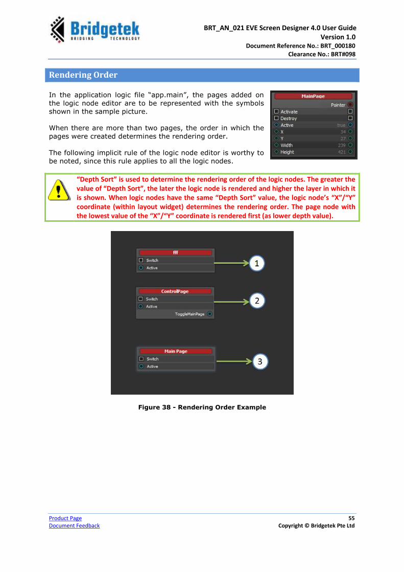
BRT_AN_021 EVE Screen Designer 4.0 User Guide Version 1.0 Document Reference No.: BRT_000180
Clearance No.: BRT#098
Product Page 55
Document Feedback Copyright © Bridgetek Pte Ltd
Rendering Order
In the application logic file “app.main”, the pages added on
the logic node editor are to be represented with the symbols
shown in the sample picture.
When there are more than two pages, the order in which the
pages were created determines the rendering order.
The following implicit rule of the logic node editor is worthy to
be noted, since this rule applies to all the logic nodes.
“Depth Sort” is used to determine the rendering order of the logic nodes. The greater the value of “Depth Sort”, the later the logic node is rendered and higher the layer in which it is shown. When logic nodes have the same “Depth Sort” value, the logic node’s “X”/“Y” coordinate (within layout widget) determines the rendering order. The page node with the lowest value of the “X”/“Y” coordinate is rendered first (as lower depth value).
Figure 38 - Rendering Order Example

BRT_AN_021 EVE Screen Designer 4.0 User Guide Version 1.0 Document Reference No.: BRT_000180
Clearance No.: BRT#098
Product Page 56
Document Feedback Copyright © Bridgetek Pte Ltd
Logic Note Editor - Zoom In & Zoom Out
The Logic Node Editor enables Zoom-in and Zoom-out functionality. Users can make use
of the mouse wheel button to zoom in and zoom out.
DON’TS
Avoid two connections connecting to the same port. Refer to the sample picture given below.
Avoid endless dead loops caused by connecting the input and output of the same object. It will cause an unexpected error. Refer to the sample pictures given below.
To effect the changes made to the logic note editor, ensure that all the changes are saved to the project, by clicking “File → Save All” from the menu or toolbar. In some
cases, click the “Recompile” button to recompile the source code generated by ESD.
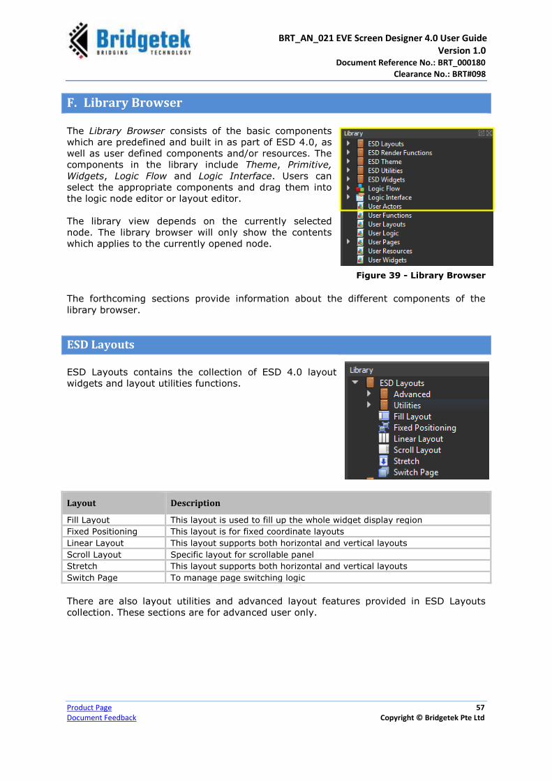
BRT_AN_021 EVE Screen Designer 4.0 User Guide Version 1.0 Document Reference No.: BRT_000180
Clearance No.: BRT#098
Product Page 57
Document Feedback Copyright © Bridgetek Pte Ltd
F. Library Browser
The Library Browser consists of the basic components
which are predefined and built in as part of ESD 4.0, as
well as user defined components and/or resources. The
components in the library include Theme, Primitive,
Widgets, Logic Flow and Logic Interface. Users can
select the appropriate components and drag them into
the logic node editor or layout editor.
The library view depends on the currently selected
node. The library browser will only show the contents
which applies to the currently opened node.
Figure 39 - Library Browser
The forthcoming sections provide information about the different components of the
library browser.
ESD Layouts
ESD Layouts contains the collection of ESD 4.0 layout
widgets and layout utilities functions.
Layout Description
Fill Layout This layout is used to fill up the whole widget display region
Fixed Positioning This layout is for fixed coordinate layouts
Linear Layout This layout supports both horizontal and vertical layouts
Scroll Layout Specific layout for scrollable panel
Stretch This layout supports both horizontal and vertical layouts
Switch Page To manage page switching logic
There are also layout utilities and advanced layout features provided in ESD Layouts
collection. These sections are for advanced user only.

BRT_AN_021 EVE Screen Designer 4.0 User Guide Version 1.0 Document Reference No.: BRT_000180
Clearance No.: BRT#098
Product Page 58
Document Feedback Copyright © Bridgetek Pte Ltd
Switch Page
The Switch Page is a special layout which focuses on page/widget transitions. By default,
there will be only one Switch Page layout in “AppScreen.Page” in every ESD project.
However, this is optional and the users can remove or change the switch page layout in
the project. Refer to the example project “EVE Screen Designer ->Examples ->Basic
-> MenuPage ->MenuPage.esd->AppScreen.page” for a switch page demo.
Property Name Description
Pointer The pointer reference of the widget object
Active Enable or disable displaying this widget
X x coordinate of the top-left of the widget, in pixels
Y Y coordinate of the top-left of the widget, in pixels
Width Widget width
Height Widget Height
Spinner Set true to show spinner/loading icon when switching page. This is useful user indication when a page has heavy resource.
Scissor Set true, to trim off any content is drawn outside the layout
region.
AutoResize Set true, to enable auto resize for this layout.
Table 7 – Switch Page Layout Properties
Switch Page Implementation
1. Set page/widget into Switch Page
Unlike widgets, Switch Page can be dragged on neither
Screen Layout Editor nor Logic Editor. In order to put a
page under the control of the switch page layout, the user
has to use Project Browser instead, drag the widget into
the switch page layout.
2. Page Resource
Since ESD 4.0, a page resource allocation can be:
• Static – always load at the start
• Lazy – allocate when it is active, and free it when it is inactive.
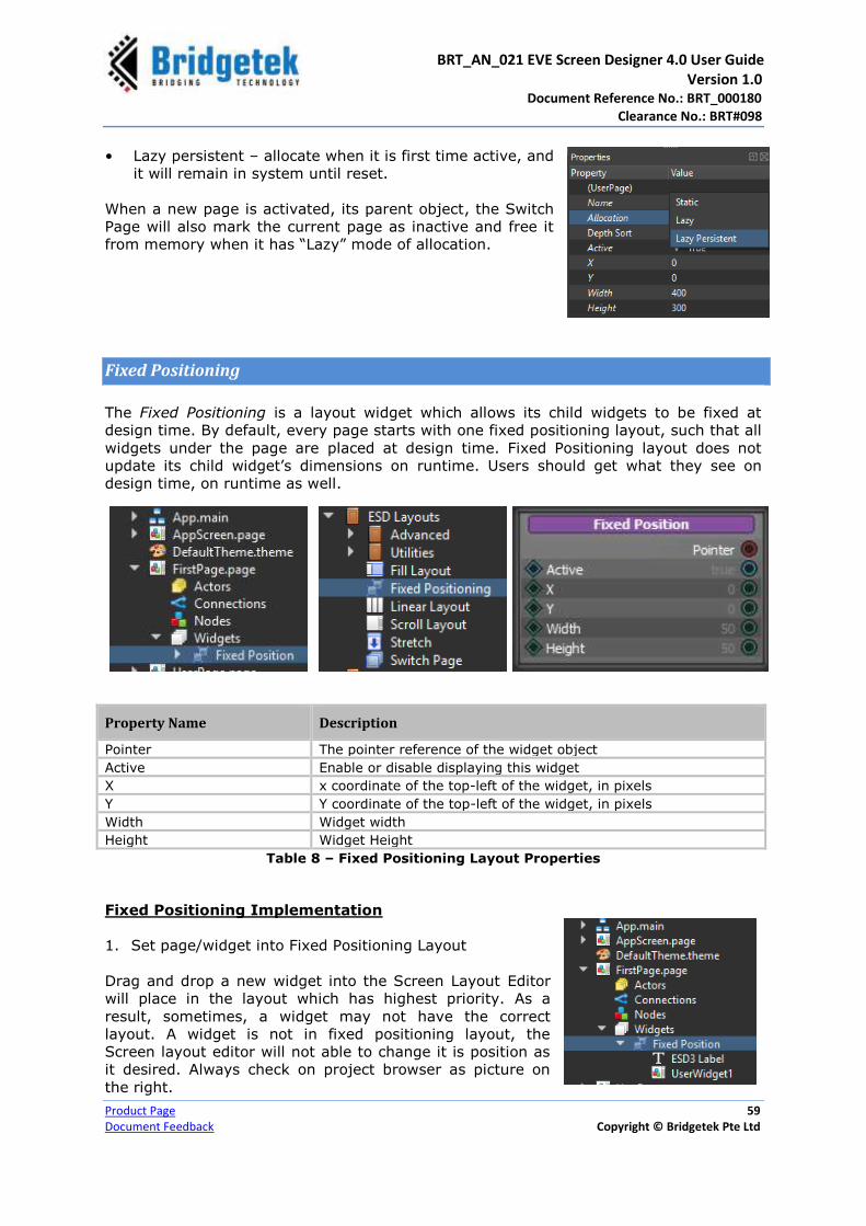
BRT_AN_021 EVE Screen Designer 4.0 User Guide Version 1.0 Document Reference No.: BRT_000180
Clearance No.: BRT#098
Product Page 59
Document Feedback Copyright © Bridgetek Pte Ltd
• Lazy persistent – allocate when it is first time active, and
it will remain in system until reset.
When a new page is activated, its parent object, the Switch
Page will also mark the current page as inactive and free it
from memory when it has “Lazy” mode of allocation.
Fixed Positioning
The Fixed Positioning is a layout widget which allows its child widgets to be fixed at
design time. By default, every page starts with one fixed positioning layout, such that all
widgets under the page are placed at design time. Fixed Positioning layout does not
update its child widget’s dimensions on runtime. Users should get what they see on
design time, on runtime as well.
Property Name Description
Pointer The pointer reference of the widget object
Active Enable or disable displaying this widget
X x coordinate of the top-left of the widget, in pixels
Y Y coordinate of the top-left of the widget, in pixels
Width Widget width
Height Widget Height
Table 8 – Fixed Positioning Layout Properties
Fixed Positioning Implementation
1. Set page/widget into Fixed Positioning Layout
Drag and drop a new widget into the Screen Layout Editor
will place in the layout which has highest priority. As a
result, sometimes, a widget may not have the correct
layout. A widget is not in fixed positioning layout, the
Screen layout editor will not able to change it is position as
it desired. Always check on project browser as picture on
the right.
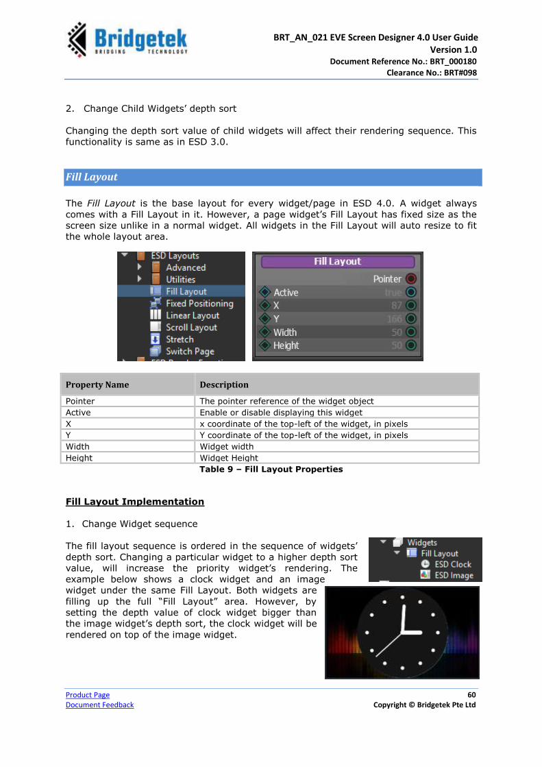
BRT_AN_021 EVE Screen Designer 4.0 User Guide Version 1.0 Document Reference No.: BRT_000180
Clearance No.: BRT#098
Product Page 60
Document Feedback Copyright © Bridgetek Pte Ltd
2. Change Child Widgets’ depth sort
Changing the depth sort value of child widgets will affect their rendering sequence. This
functionality is same as in ESD 3.0.
Fill Layout
The Fill Layout is the base layout for every widget/page in ESD 4.0. A widget always
comes with a Fill Layout in it. However, a page widget’s Fill Layout has fixed size as the
screen size unlike in a normal widget. All widgets in the Fill Layout will auto resize to fit
the whole layout area.
Property Name Description
Pointer The pointer reference of the widget object
Active Enable or disable displaying this widget
X x coordinate of the top-left of the widget, in pixels
Y Y coordinate of the top-left of the widget, in pixels
Width Widget width
Height Widget Height
Table 9 – Fill Layout Properties
Fill Layout Implementation
1. Change Widget sequence
The fill layout sequence is ordered in the sequence of widgets’
depth sort. Changing a particular widget to a higher depth sort
value, will increase the priority widget’s rendering. The
example below shows a clock widget and an image
widget under the same Fill Layout. Both widgets are
filling up the full “Fill Layout” area. However, by
setting the depth value of clock widget bigger than
the image widget’s depth sort, the clock widget will be
rendered on top of the image widget.

BRT_AN_021 EVE Screen Designer 4.0 User Guide Version 1.0 Document Reference No.: BRT_000180
Clearance No.: BRT#098
Product Page 61
Document Feedback Copyright © Bridgetek Pte Ltd
Linear Layout
The Linear Layout supports both horizontal and vertical alignment in ESD 4.0. All child
widgets will be distributed in the selected orientation. Users cannot change the sequence
of widgets in the linear layout from Screen Layout Designer in ESD 4.0. However,
changing their depth sort value from the property browser will change the sequence.
Property Name Description
Pointer The pointer reference of the widget object
Active Enable or disable displaying this widget
X x coordinate of the top-left of the widget, in pixels
Y Y coordinate of the top-left of the widget, in pixels
Width Widget width
Height Widget Height
Spacing Set the spacing gay between adjacent child widgets.
Orientation Set Linear Layout orientation. It supports: ESD_ORIENTATION_HORIZONTAL ESD_ORIENTATION_VERTICAL
Alignment Set the alignment setting for the child widgets in the layout
Overflow Set child widget overflow mode. It supports:
ESD_OVERFLOW_ALLOW ESD_OVERFLOW_CLIP ESD_OVERFLOW_FILL
Scissor Set true to enable scissor to clip off overflow
ChildClipping Set the flags when child clipping should check. It supports: ESD_CLIP_RENDER ESD_CLIP_UPDATE
ESD_CLIP_IDLE
AutoResize Set auto resize mode for this layout.
Table 10 – Linear Layout Properties
Linear Layout Implementation
1. Horizontal Layout
All child widgets of a linear layout with its orientation are set to
“ESD_ORIENTATION_HORIZONTAL”. They will be distributed horizontally with some
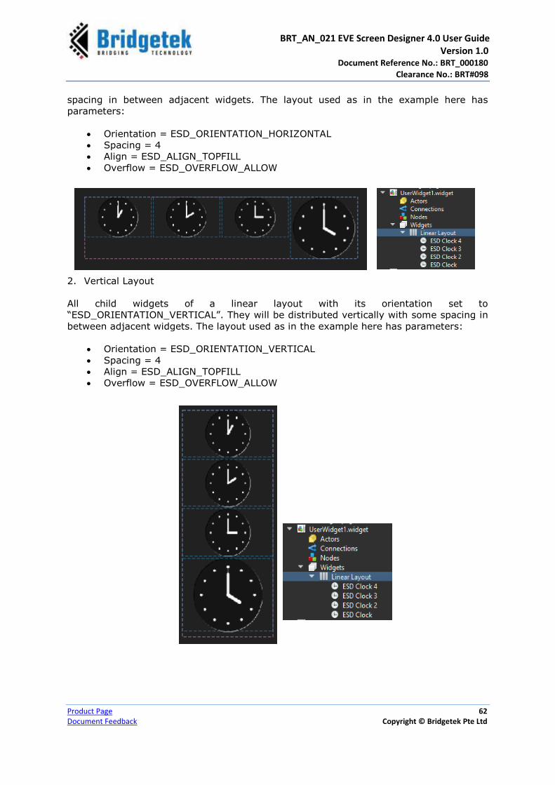
BRT_AN_021 EVE Screen Designer 4.0 User Guide Version 1.0 Document Reference No.: BRT_000180
Clearance No.: BRT#098
Product Page 62
Document Feedback Copyright © Bridgetek Pte Ltd
spacing in between adjacent widgets. The layout used as in the example here has
parameters:
Orientation = ESD_ORIENTATION_HORIZONTAL
Spacing = 4
Align = ESD_ALIGN_TOPFILL
Overflow = ESD_OVERFLOW_ALLOW
2. Vertical Layout
All child widgets of a linear layout with its orientation set to
“ESD_ORIENTATION_VERTICAL”. They will be distributed vertically with some spacing in
between adjacent widgets. The layout used as in the example here has parameters:
Orientation = ESD_ORIENTATION_VERTICAL
Spacing = 4
Align = ESD_ALIGN_TOPFILL
Overflow = ESD_OVERFLOW_ALLOW

BRT_AN_021 EVE Screen Designer 4.0 User Guide Version 1.0 Document Reference No.: BRT_000180
Clearance No.: BRT#098
Product Page 63
Document Feedback Copyright © Bridgetek Pte Ltd
Stretch
The Stretch Layout is
designed to work together
with the linear layout. In the
event some widgets need to
have higher weightage in the
layout, Stretch Layouts are
used.
Property Name Description
Pointer The pointer reference of the widget object
Active Enable or disable displaying this widget
X x coordinate of the top-left of the widget, in pixels
Y Y coordinate of the top-left of the widget, in pixels
Width Widget width
Height Widget Height
Weight The weight factor when determine the stretch scale in the
selected orientation
Table 11 – Stretch Layout Properties
Stretch Layout Implementation
1. Space Stretching
The example here demonstrates how to stretch unused
space horizontally. A stretch layout has been added into
the Linear Layout. The weight factor used here is 1.
2. Widget Weight Stretching
The example here demonstrates widget stretching. In this
example, every clock widget has different stretch weight
values. The result every widget gains their proportion of
width as shown below.

BRT_AN_021 EVE Screen Designer 4.0 User Guide Version 1.0 Document Reference No.: BRT_000180
Clearance No.: BRT#098
Product Page 64
Document Feedback Copyright © Bridgetek Pte Ltd
Scroll Layout
The Scroll Layout is a support
runtime resizable and scrollable
layout in ESD 4.0.
Property Name Description
Pointer The pointer reference of the widget object
Active Enable or disable displaying this widget
X x coordinate of the top-left of the widget, in pixels
Y Y coordinate of the top-left of the widget, in pixels
Width Widget width
Height Widget Height
ScrollX Getter and Setter for scroll value along X-axis
ScrollY Getter and Setter for scroll value along Y-axis
Align Set alignment for its child widgets
Scrollbars Set when scrollbar should be visible
TouchScroll Set true to enable touch scroll
Scroll Bar Size To set scroll bar size when it is visible
Table 12 – Scroll Layout Properties
Scroll Layout Implementation
For the implementation of scroll layout, refer to the example project - “EVE Screen
Designer ->Examples ->Intermediate -> ScrollPanel.
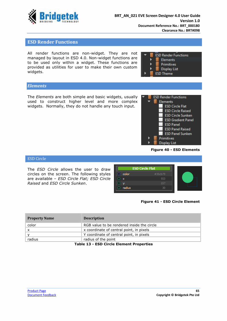
BRT_AN_021 EVE Screen Designer 4.0 User Guide Version 1.0 Document Reference No.: BRT_000180
Clearance No.: BRT#098
Product Page 65
Document Feedback Copyright © Bridgetek Pte Ltd
ESD Render Functions
All render functions are non-widget. They are not
managed by layout in ESD 4.0. Non-widget functions are
to be used only within a widget. These functions are
provided as utilities for user to make their own custom
widgets.
Elements
The Elements are both simple and basic widgets, usually
used to construct higher level and more complex
widgets. Normally, they do not handle any touch input.
Figure 40 - ESD Elements
ESD Circle
The ESD Circle allows the user to draw
circles on the screen. The following styles
are available – ESD Circle Flat; ESD Circle
Raised and ESD Circle Sunken.
Figure 41 - ESD Circle Element
Property Name Description
color RGB value to be rendered inside the circle
x x coordinate of central point, in pixels
y Y coordinate of central point, in pixels
radius radius of the point
Table 13 - ESD Circle Element Properties
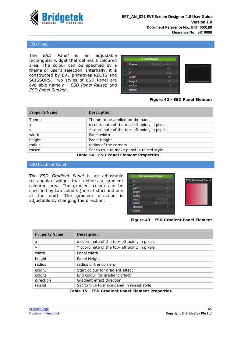
BRT_AN_021 EVE Screen Designer 4.0 User Guide Version 1.0 Document Reference No.: BRT_000180
Clearance No.: BRT#098
Product Page 66
Document Feedback Copyright © Bridgetek Pte Ltd
ESD Panel
The ESD Panel is an adjustable
rectangular widget that defines a coloured
area. The colour can be specified by a
theme or user’s selection. Internally, it is
constructed by EVE primitives RECTS and
SCISSORS. Two styles of ESD Panel are
available namely – ESD Panel Raised and
ESD Panel Sunken.
Figure 42 - ESD Panel Element
Property Name Description
Theme Theme to be applied on the panel
x x coordinate of the top-left point, in pixels
y Y coordinate of the top-left point, in pixels
width Panel width
height Panel Height
radius radius of the corners
raised Set to true to make panel in raised style
Table 14 - ESD Panel Element Properties
ESD Gradient Panel
The ESD Gradient Panel is an adjustable
rectangular widget that defines a gradient
coloured area. The gradient colour can be
specified by two colours (one at start and one
at the end). The gradient direction is
adjustable by changing the direction.
Figure 43 - ESD Gradient Panel Element
Property Name Description
x x coordinate of the top-left point, in pixels
y Y coordinate of the top-left point, in pixels
width Panel width
height Panel Height
radius radius of the corners
color1 Start colour for gradient effect
color2 End colour for gradient effect
direction Gradient effect direction
raised Set to true to make panel in raised style
Table 15 - ESD Gradient Panel Element Properties

BRT_AN_021 EVE Screen Designer 4.0 User Guide Version 1.0 Document Reference No.: BRT_000180
Clearance No.: BRT#098
Product Page 67
Document Feedback Copyright © Bridgetek Pte Ltd
Primitives
A Primitive is a special type of logic node which is a
wrapper for a rendering function called by Render slot. It
has no return value and its properties cannot be output to
other logic nodes. Similar to widgets, it appears on the
screen, but is unable to handle user input.
Figure 44 - ESD 4.0Primitives
ESD Bitmap
The ESD Bitmap object allows users to display a
bitmap resource. A bitmap resource is generated
from an image file by adding it into a project. A
bitmap resource is treated as a single bitmap cell
by default with the name “(Bitmap Resource)_0”.
For example, if the bitmap resource is named
“photo.jpg”, the default bitmap resource will be
named as “photo_0”. Users can define how many
bitmap cells they want by specifying the
“CellHeight” property.
Figure 45 - ESD Bitmap Primitive
Property Name Description
x x coordinate of Bitmap, top-left, in pixels
y Y coordinate of Bitmap, top-left, in pixels
Bitmap Cell Bitmap cell to display
Color Color to be applied to bitmap
Table 16 - ESD Bitmap Properties

BRT_AN_021 EVE Screen Designer 4.0 User Guide Version 1.0 Document Reference No.: BRT_000180
Clearance No.: BRT#098
Product Page 68
Document Feedback Copyright © Bridgetek Pte Ltd
To add a bitmap
Click and select “File → Add” or click from the
toolbar. A bitmap cell is then assigned. ESD
4.0 supports the following image file formats as input –
“.png”, “.jpg” and “.jpeg”. Bitmap resources can contain a
single or multiple cells based on the CellHeight value.
If the value of the “CellHeight” is zero, then the number of
cells is one.
If the value of the “CellHeight” is non-zero, then the number
of cells value is calculated as shown below –
Number of Cell = Bitmap Height / CellHeight
Upon adding a Bitmap, the new bitmap resource will be
added into the Library under the category – “User
Resources”.
To use an ESD Bitmap, drag and drop the ESD Bitmap Node into the Layout Editor or
Logic Node Editor.
Choose a Bitmap Cell to display from the dropdown list.
Library
Browser

BRT_AN_021 EVE Screen Designer 4.0 User Guide Version 1.0 Document Reference No.: BRT_000180
Clearance No.: BRT#098
Product Page 69
Document Feedback Copyright © Bridgetek Pte Ltd
The list of Bitmap Cell values is updated automatically after a new image file is added
into a project.
Use ESD Image to display bitmap as ESD bitmap is non-widget, and used only as a rendering function in ESD 4.0. Users are required to upgrade ESD Bitmap to ESD Image.
ESD Line
The ESD Line allows users to draw lines on the
screen.
Figure 46 - ESD Line
Use ESD Widgets – Line Widget to display line as ESD line is non-widget, and used only as a rendering function in ESD 4.0. Users are required to upgrade ESD Line to Line Widget.
Property Name Description
x0 x – coordinate of the start point, in pixels
y0 y – coordinate of the start point, in pixels
x1 x – coordinate of the end point, in pixels
y1 y – coordinate of the end point, in pixels
width Line width, in pixel
Color Line color, in RGBA format
Table 17 - ESD Line Properties
Fixed Point Variant
ESD Line (Fixed point) expresses the properties with pixel attribute in fixed point format.
It provides more control to lines.

BRT_AN_021 EVE Screen Designer 4.0 User Guide Version 1.0 Document Reference No.: BRT_000180
Clearance No.: BRT#098
Product Page 70
Document Feedback Copyright © Bridgetek Pte Ltd
ESD Rectangle
The ESD Rectangle allows users to draw
rectangle on the screen.
Figure 47 - ESD Rectangle
Property Name Description
x x coordinate of Bitmap, top-left, in pixels
y Y coordinate of Bitmap, top-left, in pixels
width width, in pixels
height height, in pixels
radius radius of the round corner, in pixels
Color color of the rectangle
Table 18 - ESD Rectangle Properties
Fixed Point Variant
ESD Rectangle (Fixed point) expresses the properties with pixel attribute in fixed point
format. It provides more control to rectangles.
Display List
The Display List provides a collection of utilities functions related
to EVE Display List..
Figure 48 - ESD Display List

BRT_AN_021 EVE Screen Designer 4.0 User Guide Version 1.0 Document Reference No.: BRT_000180
Clearance No.: BRT#098
Product Page 71
Document Feedback Copyright © Bridgetek Pte Ltd
ESD Theme
A Theme is a collection of colours which can be used across
the application in order to maintain a consistent style. The
library browser provides the necessary logic nodes to make
most use of the theme function.
Figure 49 - Library Browser - ESD Theme
Built In Themes
ESD 4.0 provides two Built-in Themes for users to configure the colour scheme of
project. They are: Ft_Esd_Theme_LightBlue theme and Ft_Esd_Theme_DarkOrange
theme.
Figure 50 - ESD 4.0 Built-in Themes
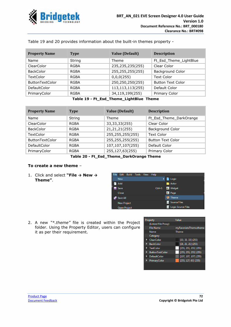
BRT_AN_021 EVE Screen Designer 4.0 User Guide Version 1.0 Document Reference No.: BRT_000180
Clearance No.: BRT#098
Product Page 72
Document Feedback Copyright © Bridgetek Pte Ltd
Table 19 and 20 provides information about the built-in themes property -
Property Name Type Value (Default) Description
Name String Theme Ft_Esd_Theme_LightBlue
ClearColor RGBA 235,235,235(255) Clear Color
BackColor RGBA 255,255,255(255) Background Color
TextColor RGBA 0,0,0(255) Text Color
ButtonTextColor RGBA 250,250,250(255) Button Text Color
DefaultColor RGBA 113,113,113(255) Default Color
PrimaryColor RGBA 34,119,199(255) Primary Color
Table 19 - Ft_Esd_Theme_LightBlue Theme
Property Name Type Value (Default) Description
Name String Theme Ft_Esd_Theme_DarkOrange
ClearColor RGBA 33,33,33(255) Clear Color
BackColor RGBA 21,21,21(255) Background Color
TextColor RGBA 255,255,255(255) Text Color
ButtonTextColor RGBA 255,255,255(255) Button Text Color
DefaultColor RGBA 107,107,107(255) Default Color
PrimaryColor RGBA 255,127,63(255) Primary Color
Table 20 - Ft_Esd_Theme_DarkOrange Theme
To create a new theme –
1. Click and select “File → New →
Theme”.
2. A new “*.theme” file is created within the Project
folder. Using the Property Editor, users can configure
it as per their requirement.

BRT_AN_021 EVE Screen Designer 4.0 User Guide Version 1.0 Document Reference No.: BRT_000180
Clearance No.: BRT#098
Product Page 73
Document Feedback Copyright © Bridgetek Pte Ltd
3. The newly-created theme will be available across the
project and may be applied it to other widgets with
the theme property.
4. The newly created theme will also be available under
User Resources in the Library Browser. Users can drag
and drop the theme to the logic editor.
ESD Utilities
ESD Utilities contains the collection ESD utilities functions. The
following table provides the list of ESD Utilities and its
functionality.

BRT_AN_021 EVE Screen Designer 4.0 User Guide Version 1.0 Document Reference No.: BRT_000180
Clearance No.: BRT#098
Product Page 74
Document Feedback Copyright © Bridgetek Pte Ltd
ESD Utility Description
ESD BitmapCell GetInfo Retrieves the BitmapCell information with given bitmap reference.
ESD BitmapInfo GetHeight Returns the BitmapCell Height of given bitmap reference.
ESD BitmapInfo GetWidth Retrieves the BitmapCell Width of given bitmap reference.
Bitmap Persist To persist the given bitmap object
Color A+RGB Combine Merge Alpha to RGB, to become RGBA colour
Clamp Float Clamp float value with min and max limits
Get Delta Ms Get Delta time difference in milliseconds since last frame update called
Get Font Height Return Font Height
Get EVE Host Get EVE Host
Get Milliseconds Get time in mili-seconds for current frame
Clamp Int16/UInt16 Clamp Int16/UInt16 value with min and max limits
Clamp Int32/UInt32 Clamp Int32/UInt32 value with min and max limits
Load Bitmap to RAM_G Load Bitmap to RAM_G
Load Palette to RAM_G Load Palette to RAM_G
Pop-up Spinner Pop-up Spinner when the frame is rendered
Switch Bitmap Cell Switch Bitmap Cell
ESD Timer ESD Timer Actor
Touch Area Touch Area Actor
Touch Scroll Touch Scroll Actor
Touch Tag Touch Tag Actor
Current Tag Current Touch Tag
Suppress Current Tags Suppress Current Tags
Touch X/Y Touch X/Y coordinate
Touch X/Y Delta Touch X/Y Delta
Table 21 – ESD Utilities & Description
ESD Widgets
A widget is a kind of logic node which has a visual appearance
rendered by the Embedded Video Engine (EVE). The widgets can
be found in the library browser area. There are two types of
widgets – ESD Widgets (built-in widgets provided by ESD) and
User Widgets (defined by users). Users can browse for all the
available widgets easily from the library browser.
Figure 51 – Widgets
Basic Widgets
ESD Basic widgets are introduced in ESD 4.0. These widgets are the widget wrappers for
the Elemental and Primitive Rendering functions which include drawing line, paint
rectangle, paint circle and paint bitmap.
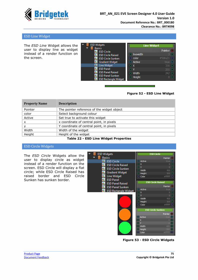
BRT_AN_021 EVE Screen Designer 4.0 User Guide Version 1.0 Document Reference No.: BRT_000180
Clearance No.: BRT#098
Product Page 75
Document Feedback Copyright © Bridgetek Pte Ltd
ESD Line Widget
The ESD Line Widget allows the
user to display line as widget
instead of a render function on
the screen.
Figure 52 - ESD Line Widget
Property Name Description
Pointer The pointer reference of the widget object
color Select background colour
Active Set true to activate this widget
x x coordinate of central point, in pixels
y Y coordinate of central point, in pixels
Width Width of the widget
Height Height of the widget
Table 22 - ESD Line Widget Properties
ESD Circle Widgets
The ESD Circle Widgets allow the
user to display circle as widget
instead of a render function on the
screen. ESD Circle will display a flat
circle; while ESD Circle Raised has
raised border and ESD Circle
Sunken has sunken border.
Figure 53 - ESD Circle Widgets

BRT_AN_021 EVE Screen Designer 4.0 User Guide Version 1.0 Document Reference No.: BRT_000180
Clearance No.: BRT#098
Product Page 76
Document Feedback Copyright © Bridgetek Pte Ltd
Property Name Description
Pointer The pointer reference of the widget object
Active Set true if this widget is active.
color RGB value to be rendered inside the circle
x x coordinate of central point, in pixels
y Y coordinate of central point, in pixels
radius Radius of the point
Table 23 - ESD Circle Element Properties
ESD Panel Widgets
The ESD Panel Widgets allow the user
to display panel as widget instead of
a render function on the screen. ESD
Panel will display a configurable
raised/sunken panel; while ESD Panel
Raised has raised border and ESD
Panel Sunken has sunken border.
Both ESD Panel Raised and ESD
Panel Sunken can set the
background colour.
Figure 54 - ESD Panel Widgets
Property Name Description
Pointer The pointer reference of the widget object
theme Select the theme which affect the background colour
raised Set true for raised border, else it will be sunken border
x x coordinate of central point, in pixels
y Y coordinate of central point, in pixels
radius radius of the point
Table 24 - ESD Panel Widget Properties

BRT_AN_021 EVE Screen Designer 4.0 User Guide Version 1.0 Document Reference No.: BRT_000180
Clearance No.: BRT#098
Product Page 77
Document Feedback Copyright © Bridgetek Pte Ltd
Property Name Description
Pointer The pointer reference of the widget object
color Select background colour
Active Set true to activate this widget
x x coordinate of central point, in pixels
y Y coordinate of central point, in pixels
radius radius of the point
Table 25 - ESD Panel Raised and Sunken Widget Properties
ESD Gradient Widget
The ESD Gradient Widget
allows the user to display
gradient rectangle as widget
instead of a render function on
the screen.
Figure 55 - ESD Gradient Widget
Property Name Description
Pointer The pointer reference of the widget object
Start color Select the starting colour of the gradient effect
End color Select the ending colour of the gradient effect
direction Set the gradient effect direction in degree. The degree and value range is from 0 to 359
Active Set true to activate this widget
x x coordinate of central point, in pixels
y Y coordinate of central point, in pixels
Width Width of the widget
Height Height of the widget
Table 26 - ESD Gradient Widget Properties
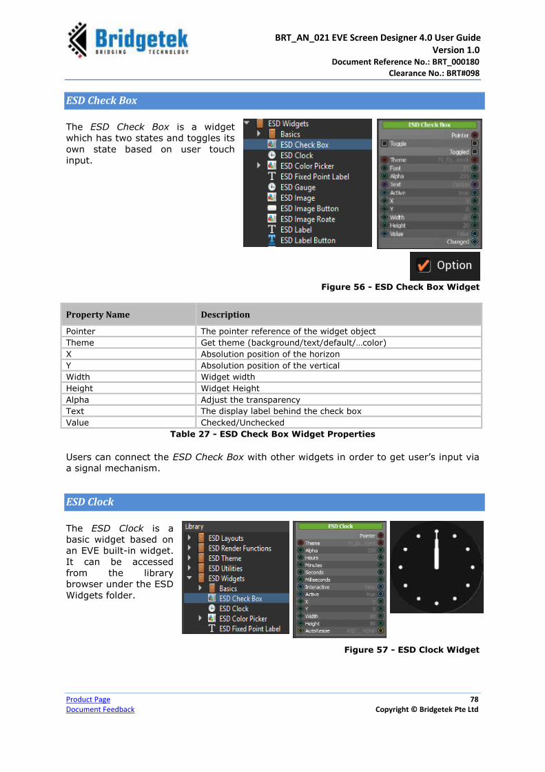
BRT_AN_021 EVE Screen Designer 4.0 User Guide Version 1.0 Document Reference No.: BRT_000180
Clearance No.: BRT#098
Product Page 78
Document Feedback Copyright © Bridgetek Pte Ltd
ESD Check Box
The ESD Check Box is a widget
which has two states and toggles its
own state based on user touch
input.
Figure 56 - ESD Check Box Widget
Property Name Description
Pointer The pointer reference of the widget object
Theme Get theme (background/text/default/…color)
X Absolution position of the horizon
Y Absolution position of the vertical
Width Widget width
Height Widget Height
Alpha Adjust the transparency
Text The display label behind the check box
Value Checked/Unchecked
Table 27 - ESD Check Box Widget Properties
Users can connect the ESD Check Box with other widgets in order to get user’s input via
a signal mechanism.
ESD Clock
The ESD Clock is a
basic widget based on
an EVE built-in widget.
It can be accessed
from the library
browser under the ESD
Widgets folder.
Figure 57 - ESD Clock Widget

BRT_AN_021 EVE Screen Designer 4.0 User Guide Version 1.0 Document Reference No.: BRT_000180
Clearance No.: BRT#098
Product Page 79
Document Feedback Copyright © Bridgetek Pte Ltd
Property Name Description
Pointer The pointer reference of the widget object
Theme Theme to be applied on the widget
Alpha Adjust the transparency
Hours The hour hand position
Minutes The minute hand position
Seconds The seconds hand position
Milliseconds The time expressed in milliseconds unit
Interactive Currently not in use
X x coordinate of the top-left of the widget, in pixels
Y Y coordinate of the top-left of the widget, in pixels
Width Widget width
Height Widget Height
Table 28 - ESD Clock Widget Properties
Users can connect the ESD clock with other widgets, such as ESD toggle or ESD timer
via hours/minutes/seconds or milliseconds property. Figure 59 shows how a clock is
started or stopped by an ESD Toggle Widget and the corresponding logic node
connection.
Figure 58 - ESD Clock Widget Example

BRT_AN_021 EVE Screen Designer 4.0 User Guide Version 1.0 Document Reference No.: BRT_000180
Clearance No.: BRT#098
Product Page 80
Document Feedback Copyright © Bridgetek Pte Ltd
ESD Color Picker
ESD Color Picker provides a circle style Colour picker which is associated with a circle
bitmap. It handles user touch and translates the touch point into a corresponding RGB
Colour value as an output. Users can connect this widget with the bitmap
“circular_colorwheel.png” under “$(LIBRARY)\Ft_Esd_Widget” after adding it into the
current project. The bitmap can be changed but it needs to be in the same style, only
with a different radius value, which can be adjusted in the Property Editor.
Figure 59 - ESD Color Picker Widget
Property Name Description
Pointer The pointer reference of the widget object
X X coordinate of the top-left, in pixels
Y Y coordinate of the top-left, in pixels
Width Widget width
Height Widget Height
Bitmap The bitmap cell used in the colour picker
Radius The radius of the circular image (in pixel)
Table 29 - ESD Color Picker Widget Properties
Output / Signal Description
Color The current colour based on the user’s touch and selected bitmap
Table 30 - ESD Color Picker Widget Output/Signal
The logic node connection in the figure 60 shows connecting the output of the ESD Color
Picker widget with the colour property of the other widget.

BRT_AN_021 EVE Screen Designer 4.0 User Guide Version 1.0 Document Reference No.: BRT_000180
Clearance No.: BRT#098
Product Page 81
Document Feedback Copyright © Bridgetek Pte Ltd
Figure 60 - ESD Color Picker Widget Example
ESD Gauge
The ESD Gauge is a circular widget
which is based on the EVE built-in
widget. It can be connected with
other widgets to display the value by
needle. This widget does not have the
capability of interacting with the
user’s touch input.
Figure 61 - ESD Gauge Widget
Property Name Description
Pointer The pointer reference of the widget object
Theme Theme to be applied to this widget
Alpha Adjust the transparency
Value Current value that the needle is pointing to
Range Value range
Major Major Division
Minor Minor Division
X Absolution position of the horizon
Y Absolution position of the vertical
Width Widget width
Height Widget Height Table 31 - ESD Gauge Widget Properties

BRT_AN_021 EVE Screen Designer 4.0 User Guide Version 1.0 Document Reference No.: BRT_000180
Clearance No.: BRT#098
Product Page 82
Document Feedback Copyright © Bridgetek Pte Ltd
An ESD Gauge can display the temperature, speed, pressure etc.
Figure 62 – ESD Gauge Example displays the current pressure inside a
tire. Users can control a pump by increasing/decreasing pressure on
the screen.
Figure 62 - ESD Gauge Example
The corresponding logic node connection
in the logic note editor is shown in Figure
63.
Figure 63 - ESD Gauge Logic Node Connection Example
ESD Image
The ESD Image is the standard image widget that allows users to display a bitmap
resource. To rotate an image, use the ESD Image Rotate widget.
Figure 64 - ESD Image Widget
Property Name Description
Pointer The pointer reference of the widget object
Bitmap Cell The bitmap cell to be display on the widget
Active Set true if this widget is active.

BRT_AN_021 EVE Screen Designer 4.0 User Guide Version 1.0 Document Reference No.: BRT_000180
Clearance No.: BRT#098
Product Page 83
Document Feedback Copyright © Bridgetek Pte Ltd
X X coordinate of the image button, top-left, in pixels
Y Y coordinate of the image button, top-left, in pixels
Width Image button width, in pixels
Height Image button height, in pixels
Color Default colour
Align Set Image alignment mode
Scaling Set Image scaling mode
AutoResize Set Widget Auto resize mode
ScaleX X Scale value for the image
ScaleY Y Scale value for the image
Table 32 - ESD Image Properties
ESD Image Button
The ESD Image Button allows the
users to add a button in the form of a
bitmap.
Figure 65 - ESD Image Button
Property Name Description
Pointer The pointer reference of the widget object
Bitmap Normal Bitmap cell to display in the normal state
Bitmap Pressed Bitmap cell to display in the pressed state
Active Active state of the image button, set to true to appear on the screen
X X coordinate of the image button, top-left, in pixels
Y Y coordinate of the image button, top-left, in pixels
Width Image button width, in pixels
Height Image button height, in pixels
Color Default colour
Align Set Image alignment mode
Scaling Set Image scaling mode
AutoResize Set Widget Auto resize mode
ScaleX X Scale value for the image
ScaleY Y Scale value for the image
Table 33 - ESD Image Button Properties
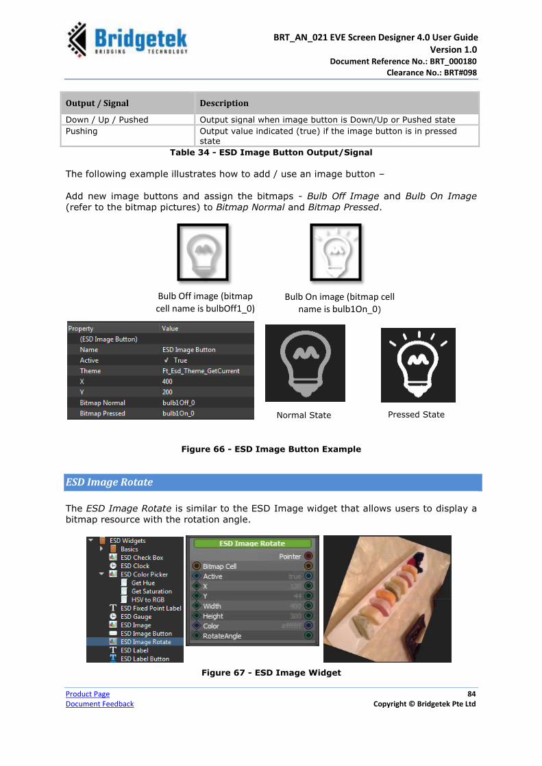
BRT_AN_021 EVE Screen Designer 4.0 User Guide Version 1.0 Document Reference No.: BRT_000180
Clearance No.: BRT#098
Product Page 84
Document Feedback Copyright © Bridgetek Pte Ltd
Output / Signal Description
Down / Up / Pushed Output signal when image button is Down/Up or Pushed state
Pushing Output value indicated (true) if the image button is in pressed state
Table 34 - ESD Image Button Output/Signal
The following example illustrates how to add / use an image button –
Add new image buttons and assign the bitmaps - Bulb Off Image and Bulb On Image
(refer to the bitmap pictures) to Bitmap Normal and Bitmap Pressed.
Figure 66 - ESD Image Button Example
ESD Image Rotate
The ESD Image Rotate is similar to the ESD Image widget that allows users to display a
bitmap resource with the rotation angle.
Figure 67 - ESD Image Widget
Bulb Off image (bitmap cell name is bulbOff1_0)
Bulb On image (bitmap cell name is bulb1On_0)
Normal State Pressed State

BRT_AN_021 EVE Screen Designer 4.0 User Guide Version 1.0 Document Reference No.: BRT_000180
Clearance No.: BRT#098
Product Page 85
Document Feedback Copyright © Bridgetek Pte Ltd
Property Name Description
Pointer The pointer reference of the widget object
Bitmap Cell The bitmap cell to be display on the widget
Active Set true if this widget is active.
X X coordinate of the image button, top-left, in pixels
Y Y coordinate of the image button, top-left, in pixels
Width Image button width, in pixels
Height Image button height, in pixels
Colour Default colour
Rotate Angle The Rotation Angle range: 0 to 65535
Table 35 - ESD Image Properties
ESD Label
The ESD Label allows the users to add a Text Label with customized size and text.
Figure 68 - ESD Label
Property Name Description
Pointer The pointer reference of the widget object
Theme Theme applied for the label
Font Fonts used in the label. Same as bitmap handle defined in EVE
Text The text content of the label. By default, “Label”
AlignX Horizontal alignment of text
OPT_ALIGN_LEFT: Left, OPT_ALIGN_CENTER: Center,
OPT_ALIGN_RIGHT: RIGHT
AlignY Vertical alignment of text OPT_ALIGN_TOP: Top, OPT_ALIGN_CENTER: Center, OPT_ALIGN_BOTTOM: Bottom
Active Active state of the label, set to true to appear on the screen

BRT_AN_021 EVE Screen Designer 4.0 User Guide Version 1.0 Document Reference No.: BRT_000180
Clearance No.: BRT#098
Product Page 86
Document Feedback Copyright © Bridgetek Pte Ltd
X X coordinate of label, top-left, in pixels
Y Y coordinate of label, top-left, in pixels
Width Label width, in pixels
Height Label height, in pixels
Table 36 - ESD Label Properties
ESD Numeric Label
The ESD Numeric Label allows the users to add a numeric Label with value in integer.
ESD Numeric Label outputs are similar to c function printf(“%d”) and printf(“%x”).
Figure 69 - ESD Numeric Label
Property Name Description
Pointer The pointer reference of the widget object
Theme Theme applied for the label
Font Fonts used in the label. Same as bitmap handle defined in EVE
AlignX Horizontal alignment of text OPT_ALIGN_LEFT: Left, OPT_ALIGN_CENTER: Center, OPT_ALIGN_RIGHT: RIGHT
AlignY Vertical alignment of text OPT_ALIGN_TOP: Top, OPT_ALIGN_CENTER: Center, OPT_ALIGN_BOTTOM: Bottom
AutoResize Set Widget Auto resize mode
Integer Value The integer value of the numeric label.
EnablePadding Set true to enable padding
No Of Digits Number of digits, padding will be applied when the number of digits is less.
IsZeroLeading Set true to enable ‘0’ leading as padding
IsHexDisplay Set true to enable Hexadecimal display format
Active Active state of the label, set to true to appear on the screen
X X coordinate of label, top-left, in pixels
Y Y coordinate of label, top-left, in pixels

BRT_AN_021 EVE Screen Designer 4.0 User Guide Version 1.0 Document Reference No.: BRT_000180
Clearance No.: BRT#098
Product Page 87
Document Feedback Copyright © Bridgetek Pte Ltd
Width Label width, in pixels
Height Label height, in pixels Table 37 - ESD Numeric Label Properties
ESD Fixed Point Label
The ESD Fixed Point Label allows the users to add a fixed point Label with value in fixed
point. ESD Fixed Point Label outputs are similar to c function printf(“%f”).
Figure 70 - ESD Fixed Point Label
Property Name Description
Pointer The pointer reference of the widget object
Theme Theme applied for the label
Font Fonts used in the label. Same as bitmap handle defined in EVE
Align X Horizontal alignment of text OPT_ALIGN_LEFT: Left, OPT_ALIGN_CENTER: Center, OPT_ALIGN_RIGHT: RIGHT
Align Y Vertical alignment of text OPT_ALIGN_TOP: Top, OPT_ALIGN_CENTER: Center,
OPT_ALIGN_BOTTOM: Bottom
AutoResize Set Widget Auto resize mode
Float Value The float value of the fixed point label.
EnablePadding Set true to enable padding
No Of Digits Number of digits, padding will be applied when the number of digits is less.
NoOfDigitsAfterDot Number of digits after the dot.
IsZeroLeading Set true to enable ‘0’ leading as padding
Active Active state of the label, set to true to appear on the screen
X X coordinate of label, top-left, in pixels
Y Y coordinate of label, top-left, in pixels
Width Label width, in pixels
Height Label height, in pixels Table 38 - ESD Fixed Point Label Properties
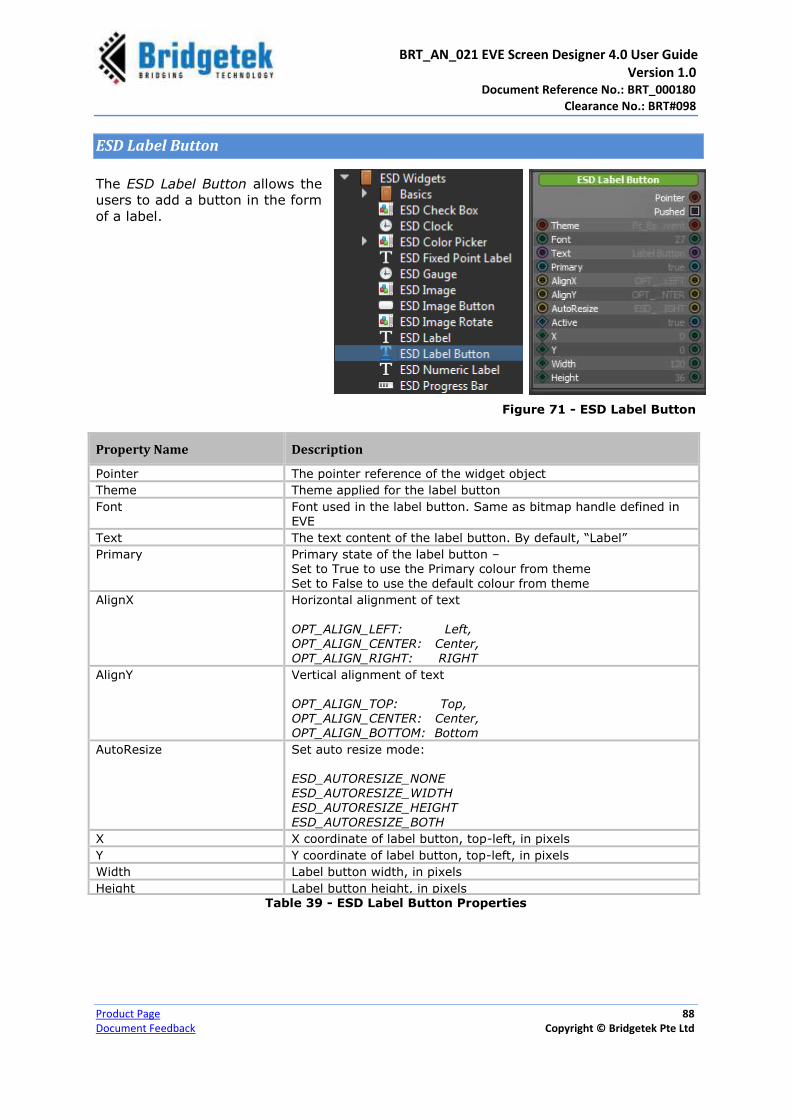
BRT_AN_021 EVE Screen Designer 4.0 User Guide Version 1.0 Document Reference No.: BRT_000180
Clearance No.: BRT#098
Product Page 88
Document Feedback Copyright © Bridgetek Pte Ltd
ESD Label Button
The ESD Label Button allows the
users to add a button in the form
of a label.
Figure 71 - ESD Label Button
Property Name Description
Pointer The pointer reference of the widget object
Theme Theme applied for the label button
Font Font used in the label button. Same as bitmap handle defined in EVE
Text The text content of the label button. By default, “Label”
Primary Primary state of the label button – Set to True to use the Primary colour from theme
Set to False to use the default colour from theme
AlignX Horizontal alignment of text
OPT_ALIGN_LEFT: Left, OPT_ALIGN_CENTER: Center, OPT_ALIGN_RIGHT: RIGHT
AlignY Vertical alignment of text OPT_ALIGN_TOP: Top, OPT_ALIGN_CENTER: Center, OPT_ALIGN_BOTTOM: Bottom
AutoResize Set auto resize mode: ESD_AUTORESIZE_NONE ESD_AUTORESIZE_WIDTH ESD_AUTORESIZE_HEIGHT
ESD_AUTORESIZE_BOTH
X X coordinate of label button, top-left, in pixels
Y Y coordinate of label button, top-left, in pixels
Width Label button width, in pixels
Height Label button height, in pixels Table 39 - ESD Label Button Properties

BRT_AN_021 EVE Screen Designer 4.0 User Guide Version 1.0 Document Reference No.: BRT_000180
Clearance No.: BRT#098
Product Page 89
Document Feedback Copyright © Bridgetek Pte Ltd
The logic node connection in Figure 72
shows how a toggle changes the state
upon pushing the label button. When
label button is pushed, the
corresponding output signal is
“Pushed”.
Figure 72 - ESD Label Button Example
ESD Radio Button and ESD Radio Group
The ESD Radio Button is used to choose options. The ESD Radio Button Group is a utility
widget which is not rendered to display. It enables multiple radio buttons to form a
single group; only one radio button can be selected at a time.
Figure 73 - ESD Radio Button & ESD Radio Group
Property Name Description
Pointer The pointer reference of the widget object
Check Selected or not selected
Theme Theme to be applied to this widget
Radio Group Pointer to a radio group
Font Font Size
Text The display label beside the radio button
Active Enable or disable displaying this widget
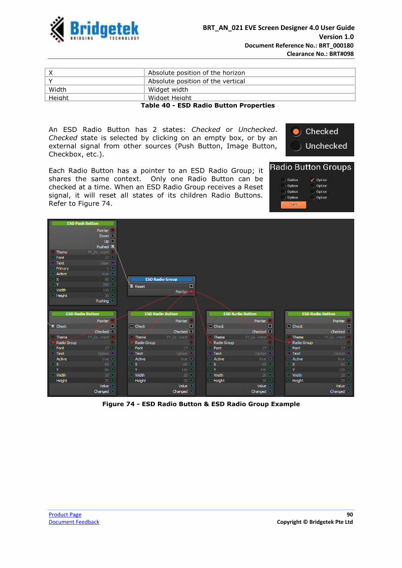
BRT_AN_021 EVE Screen Designer 4.0 User Guide Version 1.0 Document Reference No.: BRT_000180
Clearance No.: BRT#098
Product Page 90
Document Feedback Copyright © Bridgetek Pte Ltd
X Absolute position of the horizon
Y Absolute position of the vertical
Width Widget width
Height Widget Height
Table 40 - ESD Radio Button Properties
An ESD Radio Button has 2 states: Checked or Unchecked.
Checked state is selected by clicking on an empty box, or by an
external signal from other sources (Push Button, Image Button,
Checkbox, etc.).
Each Radio Button has a pointer to an ESD Radio Group; it
shares the same context. Only one Radio Button can be
checked at a time. When an ESD Radio Group receives a Reset
signal, it will reset all states of its children Radio Buttons.
Refer to Figure 74.
Figure 74 - ESD Radio Button & ESD Radio Group Example

BRT_AN_021 EVE Screen Designer 4.0 User Guide Version 1.0 Document Reference No.: BRT_000180
Clearance No.: BRT#098
Product Page 91
Document Feedback Copyright © Bridgetek Pte Ltd
ESD Push Button
The ESD Push Button allows the users to add a 3D effect rectangle button with
customized size and text label.
Figure 75 - ESD Push Button
Property Name Description
Pointer The pointer reference of the widget object
Theme Theme applied for the button
Font Fonts used in the label
Text The label displayed on the button
Primary Primary state of the button – Set to True to use the Primary color from theme Set to False to use the default color from theme
Active Active state of the button, set to true to appear on the screen
X Coordinate of button, top-left, in pixels
Y Coordinate of button, top-left, in pixels
Width Button width, in pixels
Height Button height, in pixels Table 41 - ESD Push Button Properties
Output / Signal Description
Down / Up / Pushed Output signal when the push button is Down/Up or Pushed state
Pushed Output signal when the push button is in pushed state
Table 42 - ESD Push Button Output/Signal

BRT_AN_021 EVE Screen Designer 4.0 User Guide Version 1.0 Document Reference No.: BRT_000180
Clearance No.: BRT#098
Product Page 92
Document Feedback Copyright © Bridgetek Pte Ltd
The logic node
connection in Figure
76 shows how a
Push Button
(“Button1”) is
created to toggle
the primary state of
another Push Button
(“Button 2”).
Here is the output –
Figure 76 - ESD Push Button Example
ESD Progress Bar
The ESD Progress Bar widget allows the users to add and use a progress bar.
Figure 77 - ESD Progress Bar
Property Name Description
Pointer The pointer reference of the widget object
Theme Theme to be applied on the progress bar
Value Indicates the progress level and displayed as the filled portion of the progress bar
Range Progress bar values range
Normal State Pushing State
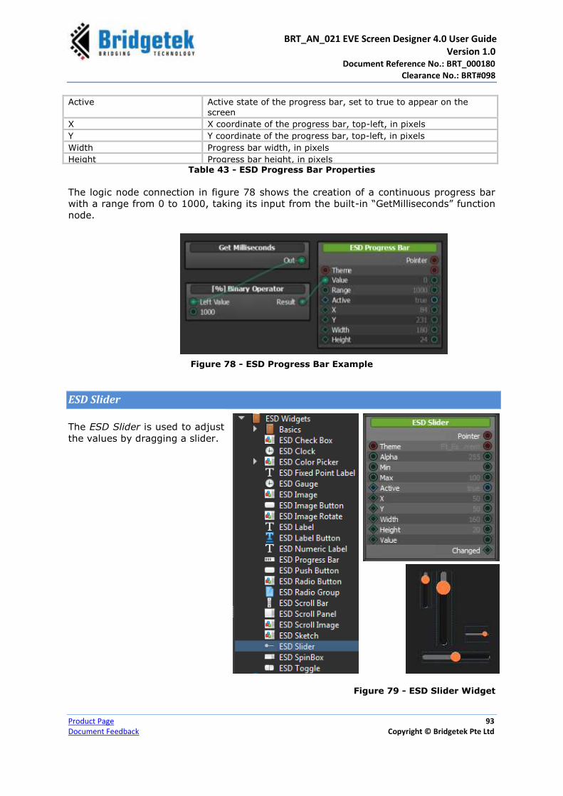
BRT_AN_021 EVE Screen Designer 4.0 User Guide Version 1.0 Document Reference No.: BRT_000180
Clearance No.: BRT#098
Product Page 93
Document Feedback Copyright © Bridgetek Pte Ltd
Active Active state of the progress bar, set to true to appear on the
screen
X X coordinate of the progress bar, top-left, in pixels
Y Y coordinate of the progress bar, top-left, in pixels
Width Progress bar width, in pixels
Height Progress bar height, in pixels Table 43 - ESD Progress Bar Properties
The logic node connection in figure 78 shows the creation of a continuous progress bar
with a range from 0 to 1000, taking its input from the built-in “GetMilliseconds” function
node.
Figure 78 - ESD Progress Bar Example
ESD Slider
The ESD Slider is used to adjust
the values by dragging a slider.
Figure 79 - ESD Slider Widget

BRT_AN_021 EVE Screen Designer 4.0 User Guide Version 1.0 Document Reference No.: BRT_000180
Clearance No.: BRT#098
Product Page 94
Document Feedback Copyright © Bridgetek Pte Ltd
Property Name Description
Pointer The pointer reference of the widget object
Theme Theme to be applied to this widget
Alpha Adjust the transparency
Min Minimum Value of the slider
Max Maximum Value of the slider
Active Enable or disable displaying this widget
X x coordinate of the top-left of the widget, in pixels
Y Y coordinate of the top-left of the widget, in pixels
Width Widget width
Height Widget Height Table 44 - ESD Slider Widget Properties
Output / Signal Description
Changed Output signal when the slider has changed
Table 45 - ESD Slider Output/Signal
The slider modifies the alpha
value and combines it with the
RGB color. The combined value
creates the ESD Rectangle
colour. It will set the connected
variable to the new value once
the value is changed. This is
illustrated in the pictures given
below –
Figure 80 - ESD Slider Example
Figure 81 shows the logic node connection in the logic note editor –
Figure 81 - ESD Slider Logic Node Connection Example

BRT_AN_021 EVE Screen Designer 4.0 User Guide Version 1.0 Document Reference No.: BRT_000180
Clearance No.: BRT#098
Product Page 95
Document Feedback Copyright © Bridgetek Pte Ltd
ESD Scroll Bar
The ESD Scroll Bar is used to scroll value between minimum and maximum which often
used together with a panel forming as scrollable panel.
Figure 82 - ESD Scroll Bar Widget
Property Name Description
Pointer The pointer reference of the widget object
Theme Theme to be applied to this widget
Max Maximum Value of the slider
Min Minimum Value of the slider
Active Enable or disable displaying this widget
X x coordinate of the top-left of the widget, in pixels
Y Y coordinate of the top-left of the widget, in pixels
Width Widget width
Height Widget Height Table 46 - ESD Scroll Bar Widget Properties
Output / Signal Description
Changed Output signal when the scroll bar has changed
Table 47 - ESD Scroll Bar Output/Signal

BRT_AN_021 EVE Screen Designer 4.0 User Guide Version 1.0 Document Reference No.: BRT_000180
Clearance No.: BRT#098
Product Page 96
Document Feedback Copyright © Bridgetek Pte Ltd
ESD Scroll Panel
The ESD Scroll Panel widget is scrollable panel, a linear layout is required to work
together. Refer to “ScrollPanel” example project for detail.
Figure 83 - ESD Scroll Panel
Property Name Description
Pointer The pointer reference of the widget object
Theme Theme to be applied to this widget
Active Enable or disable displaying this widget
X x coordinate of the top-left of the widget, in pixels
Y Y coordinate of the top-left of the widget, in pixels
Width Widget width
Height Widget Height
ScrollX Scroll to x coordinate in pixels
ScrollY Scroll to Y coordinate in pixels
Align Set alignment mode
ScrollBars Set scroll bar mode:
ESD_VISIBLE_NEVER
ESD_VISIBLE_WHENNEEDED
ESD_VISIBLE_ALWAYS
TouchScroll Set true to enable touch scroll
Scroll Bar size Set the size of scroll bar if it is applicable
Table 48 - ESD Scroll Panel Widget Properties

BRT_AN_021 EVE Screen Designer 4.0 User Guide Version 1.0 Document Reference No.: BRT_000180
Clearance No.: BRT#098
Product Page 97
Document Feedback Copyright © Bridgetek Pte Ltd
Output / Signal Description
MinX Minimum X for local X coordinate in scroll panel
MinY Minimum Y for local Y coordinate in scroll panel
MaxX Maximum X for local X coordinate in scroll panel
MaxY Maximum Y for local Y coordinate in scroll panel
RangeX X Range for local X coordinate in scroll panel
RangeY Y Range for local Y coordinate in scroll panel
Width Local width of scroll panel
Height Local height of scroll panel
ScrollXChanged Signal when X has changed
ScrollYChanged Signal when Y has changed
Table 49 - ESD Scroll Panel Output/Signal
ESD Scrollable Image
The ESD Scrollable image supports scrollable image effect by both touch and slider
controls. Refer to the example project “ScrollImageWidget” under the “EVE Screen
Designer -> Examples -> Intermediate” folder.
Figure 84 - ESD Scrollable Image
Property Name Description
Pointer The pointer reference of the widget object
SetXTouchScroll Set true to enable X axis touch scroll
SetYTouchScroll Set true to enable Y axis touch scroll
TouchOffsetThreshold The offset threshold for activating and touch scroll. This is use to stabilize the noise in touch input.
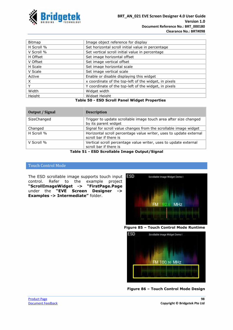
BRT_AN_021 EVE Screen Designer 4.0 User Guide Version 1.0 Document Reference No.: BRT_000180
Clearance No.: BRT#098
Product Page 98
Document Feedback Copyright © Bridgetek Pte Ltd
Bitmap Image object reference for display
H Scroll % Set horizontal scroll initial value in percentage
V Scroll % Set vertical scroll initial value in percentage
H Offset Set image horizontal offset
V Offset Set image vertical offset
H Scale Set image horizontal scale
V Scale Set image vertical scale
Active Enable or disable displaying this widget
X x coordinate of the top-left of the widget, in pixels
Y Y coordinate of the top-left of the widget, in pixels
Width Widget width
Height Widget Height Table 50 - ESD Scroll Panel Widget Properties
Output / Signal Description
SizeChanged Trigger to update scrollable image touch area after size changed
by its parent widget
Changed Signal for scroll value changes from the scrollable image widget
H Scroll % Horizontal scroll percentage value writer, uses to update external scroll bar if there is
V Scroll % Vertical scroll percentage value writer, uses to update external scroll bar if there is
Table 51 - ESD Scrollable Image Output/Signal
Touch Control Mode
The ESD scrollable image supports touch input
control. Refer to the example project
“ScrollImageWidget -> “FirstPage.Page
under the “EVE Screen Designer ->
Examples -> Intermediate” folder.
Figure 85 – Touch Control Mode Runtime
Figure 86 – Touch Control Mode Design
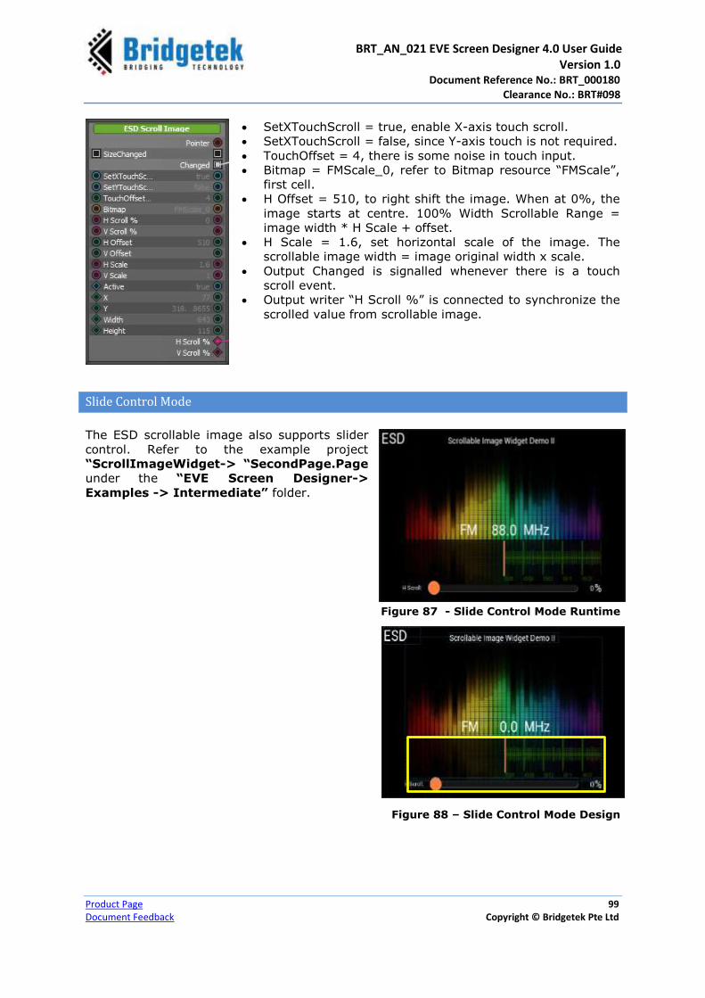
BRT_AN_021 EVE Screen Designer 4.0 User Guide Version 1.0 Document Reference No.: BRT_000180
Clearance No.: BRT#098
Product Page 99
Document Feedback Copyright © Bridgetek Pte Ltd
SetXTouchScroll = true, enable X-axis touch scroll.
SetXTouchScroll = false, since Y-axis touch is not required.
TouchOffset = 4, there is some noise in touch input.
Bitmap = FMScale_0, refer to Bitmap resource “FMScale”,
first cell.
H Offset = 510, to right shift the image. When at 0%, the
image starts at centre. 100% Width Scrollable Range =
image width * H Scale + offset.
H Scale = 1.6, set horizontal scale of the image. The
scrollable image width = image original width x scale.
Output Changed is signalled whenever there is a touch
scroll event.
Output writer “H Scroll %” is connected to synchronize the
scrolled value from scrollable image.
Slide Control Mode
The ESD scrollable image also supports slider
control. Refer to the example project
“ScrollImageWidget-> “SecondPage.Page
under the “EVE Screen Designer->
Examples -> Intermediate” folder.
Figure 87 - Slide Control Mode Runtime
Figure 88 – Slide Control Mode Design
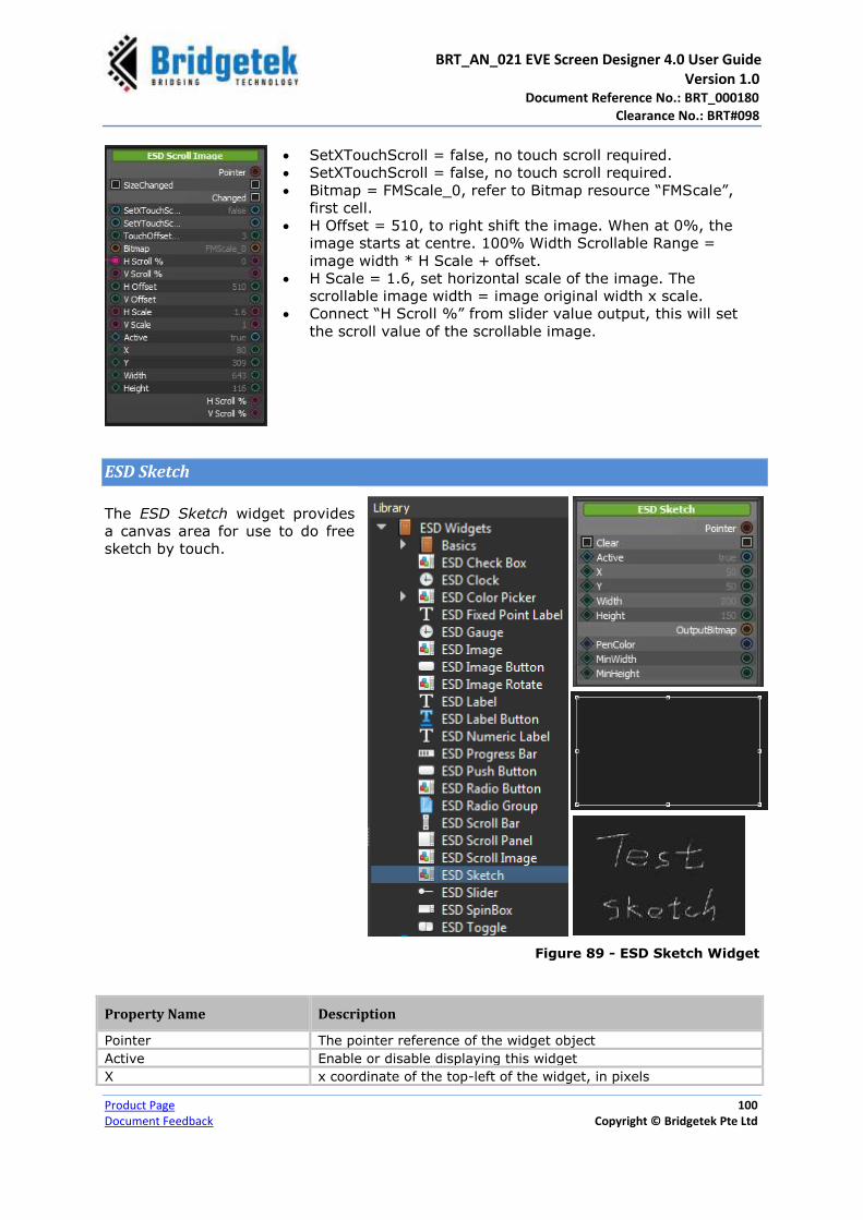
BRT_AN_021 EVE Screen Designer 4.0 User Guide Version 1.0 Document Reference No.: BRT_000180
Clearance No.: BRT#098
Product Page 100
Document Feedback Copyright © Bridgetek Pte Ltd
SetXTouchScroll = false, no touch scroll required.
SetXTouchScroll = false, no touch scroll required.
Bitmap = FMScale_0, refer to Bitmap resource “FMScale”,
first cell.
H Offset = 510, to right shift the image. When at 0%, the
image starts at centre. 100% Width Scrollable Range =
image width * H Scale + offset.
H Scale = 1.6, set horizontal scale of the image. The
scrollable image width = image original width x scale.
Connect “H Scroll %” from slider value output, this will set
the scroll value of the scrollable image.
ESD Sketch
The ESD Sketch widget provides
a canvas area for use to do free
sketch by touch.
Figure 89 - ESD Sketch Widget
Property Name Description
Pointer The pointer reference of the widget object
Active Enable or disable displaying this widget
X x coordinate of the top-left of the widget, in pixels

BRT_AN_021 EVE Screen Designer 4.0 User Guide Version 1.0 Document Reference No.: BRT_000180
Clearance No.: BRT#098
Product Page 101
Document Feedback Copyright © Bridgetek Pte Ltd
Y Y coordinate of the top-left of the widget, in pixels
Width Widget width
Height Widget Height
PenColor Color that is used to draw the trace
MinWidth Minimum Widget width when resizing the bitmap
MinHeight Minimum Widget height when resizing the bitmap
Table 52 - ESD Sketch Widget Properties
Output / Signal Description
Bitmap Cell Output the drawing as bitmap cell
Table 53 - ESD Sketch Widget Output/Signal
ESD Spin Box
The ESD Spin Box Widget
allows the users to create a
spin box with customized
style and size.
Figure 90 - ESD Spin Box
Property Name Description
Pointer The pointer reference of the widget object
Increase Input slot to trigger the increase (up) event
Decrease Input slot to trigger the decrease (down) event
Theme Theme to be applied on the spin box
Step When arrows are used to change the spin box’s value, the value will be incremented/decremented by the amount of step
Active Active state of the spin box, set to true to appear on the screen
X X coordinate of the spin box, top-left, in pixels

BRT_AN_021 EVE Screen Designer 4.0 User Guide Version 1.0 Document Reference No.: BRT_000180
Clearance No.: BRT#098
Product Page 102
Document Feedback Copyright © Bridgetek Pte Ltd
Y Y coordinate of the spin box, top-left, in pixels
Width Spin box width, in pixels
Height Spin box height, in pixels
Value Value of the spin box
SideButtons Denotes the Spin box style
Table 54 - ESD Spin Box Properties
Output / Signal Description
Increased/Decreased Output signal when the spin box is in Up (Increased)/ Down (Decreased) state
Changed Output signal, the changed value of spin box is written out
Table 55 - ESD Spin Box Output/Signal
The logic node connection in figure 91 shows the interconnection of two different styles
of ESD Spin box widgets that will increase or decrease simultaneously.
Figure 91 - ESD Spin Box Example
False (Default)
True

BRT_AN_021 EVE Screen Designer 4.0 User Guide Version 1.0 Document Reference No.: BRT_000180
Clearance No.: BRT#098
Product Page 103
Document Feedback Copyright © Bridgetek Pte Ltd
ESD Toggle
The ESD Toggle widget provides
the toggle switch functionality
with user touch enabled.
Figure 92 - ESD Toggle
Property Name Description
Theme Theme to be applied to this widget
Font The font handle used by label inside the widget
Text Toggle label
Active Enable or disable displaying this widget
X X coordinate of the top-left, in pixels
Y Y coordinate of the top-left, in pixels
Width Toggle widget width
Height Toggle widget height
State The current state of the toggle widget
AutoResize Set true to enable auto resize the toggle widget
Table 56 - ESD Toggle Widget Properties
Output / Signal Description
Toggled Output signal triggered by toggle action
Changed Output value of the changed state
Table 57 - ESD Toggle Widget Output/Signal
Figure 93 displays the creation of two toggle widgets, “Toggle1” and “Toggle2” which is
connected with the same state.

BRT_AN_021 EVE Screen Designer 4.0 User Guide Version 1.0 Document Reference No.: BRT_000180
Clearance No.: BRT#098
Product Page 104
Document Feedback Copyright © Bridgetek Pte Ltd
Figure 93 - ESD Toggle Widget Example
Logic Flow
A Logic Flow is an ESD built-in logic node. It is used to define
the logic or control flow and contains the following nodes:
Condition
Binary Condition
Binary Operator
Ternary Operator
Unary Operator
Sequence
Switch
Switch Value
Set Variable
Watch Variables
Figure 94 - Logic Flow

BRT_AN_021 EVE Screen Designer 4.0 User Guide Version 1.0 Document Reference No.: BRT_000180
Clearance No.: BRT#098
Product Page 105
Document Feedback Copyright © Bridgetek Pte Ltd
Condition
Condition node provides a set
of rules to be performed if a
certain condition is met. In
other words, it allows
applying decision points.
Figure 95 - Logic Flow – Condition Node
Whenever a condition node is called, a “Then” condition will be called when the “If”
expression is True, otherwise an “Else” condition will be called.
Ensure that the input for the “If” connection is a Boolean variable (i.e. True or False).
Binary Condition
Binary Condition node provides a set
of rules to be performed based on the
result of a binary operator on two
input values. In other words, it allows
applying decision points.
Figure 96 - Logic Flow – Binary Condition Node
Whenever a binary condition node is called, a “Then” condition will be called when the
result of binary operator on left and right value is True, otherwise an “Else” condition will
be called.
The binary operator is specified by user and it will be evaluated when the node is called
through “Do” input call.

BRT_AN_021 EVE Screen Designer 4.0 User Guide Version 1.0 Document Reference No.: BRT_000180
Clearance No.: BRT#098
Product Page 106
Document Feedback Copyright © Bridgetek Pte Ltd
Binary Operator
This node contains Binary Operator
that operates on two operands
(inputs) and manipulates them to
return an output. For example:
Result=Left Value * Right Value.
Figure 97 - Logic Flow - Binary Operator Node
The following table provides a list of binary operators supported by ESD 4.0.
Binary Operator Description
== Equal to comparison operator
!= Not Equal to comparison operator
&& Logical AND operator
& Binary AND operator
|| Logical OR operator
| Logical OR operator
* Multiplication operator
/ Division operator
% Modulus operator
^ Binary XOR operator
+ Addition operator
- Subtraction operator
, Comma operator
> Greater than operator
< Less than operator
>= Greater than or equal to
<= Less than or equal to
<< Binary Left Shift Operator
>> Binary Right Shift Operator
Table 58 - Binary Operators Supported by ESD 4.0

BRT_AN_021 EVE Screen Designer 4.0 User Guide Version 1.0 Document Reference No.: BRT_000180
Clearance No.: BRT#098
Product Page 107
Document Feedback Copyright © Bridgetek Pte Ltd
Ternary Operator
This node contains Ternary Operator that
operates on three arguments. First is the
comparison argument; second is the
result upon a true comparison and the
third is the result upon a false
comparison.
For example: Result= condition
? “Value if true”: “Value if false”.
Figure 98 - Logic Flow - Ternary Operator Node
Unary Operator
This node contains Unary Operator
that operates on a single operand
(input). For example: ~.
Figure 99 - Logic Flow - Unary Operator Node
The following table provides a list of unary operators supported by ESD 4.0.
Unary Operator Description
! Logic Negation
& Address of
* De-reference
+ Positive operator
- Negative operator
~ One’s complement
!! Non-zero value converts to 1and other values converts to 0.
Table 59 – Unary Operators Supported by ESD 4.0
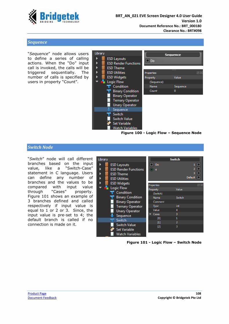
BRT_AN_021 EVE Screen Designer 4.0 User Guide Version 1.0 Document Reference No.: BRT_000180
Clearance No.: BRT#098
Product Page 108
Document Feedback Copyright © Bridgetek Pte Ltd
Sequence
“Sequence” node allows users
to define a series of calling
actions. When the “Do” input
call is invoked, the calls will be
triggered sequentially. The
number of calls is specified by
users in property “Count”.
Figure 100 - Logic Flow – Sequence Node
Switch Node
“Switch” node will call different
branches based on the input
value, like a “Switch-Case”
statement in C language. Users
can define any number of
branches and the values to be
compared with input value
through “Cases” property.
Figure 101 shows an example of
3 branches defined and called
respectively if input value is
equal to 1 or 2 or 3. Since, the
input value is pre-set to 4; the
default branch is called if no
connection is made on it.
Figure 101 - Logic Flow – Switch Node
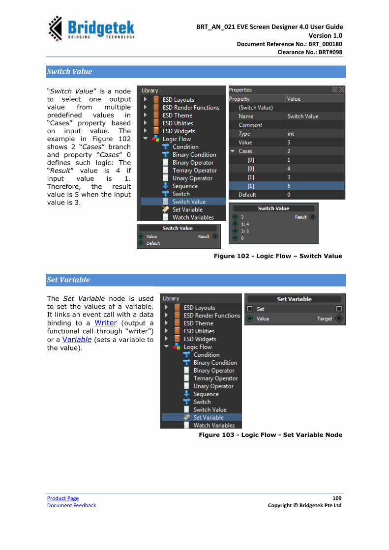
BRT_AN_021 EVE Screen Designer 4.0 User Guide Version 1.0 Document Reference No.: BRT_000180
Clearance No.: BRT#098
Product Page 109
Document Feedback Copyright © Bridgetek Pte Ltd
Switch Value
“Switch Value” is a node
to select one output
value from multiple
predefined values in
“Cases” property based
on input value. The
example in Figure 102
shows 2 “Cases” branch
and property “Cases” 0
defines such logic: The
“Result” value is 4 if
input value is 1.
Therefore, the result
value is 5 when the input
value is 3.
Figure 102 - Logic Flow – Switch Value
Set Variable
The Set Variable node is used
to set the values of a variable.
It links an event call with a data
binding to a Writer (output a
functional call through “writer”)
or a Variable (sets a variable to
the value).
Figure 103 - Logic Flow - Set Variable Node

BRT_AN_021 EVE Screen Designer 4.0 User Guide Version 1.0 Document Reference No.: BRT_000180
Clearance No.: BRT#098
Product Page 110
Document Feedback Copyright © Bridgetek Pte Ltd
Watch Variables
The Watch variables node is used to monitor a set of variable updates. A single watch
variable node can monitor ‘n’ number of variables which can be different (primitive)
types. However, the more the input variables have connected, the more frequent the
output “Changed” will be triggered. User can also connect input slots:
“Check” – used to trigger an immediate check for the input variables against
previously checked values.
“Reset” – set base values as current input values, and monitors changes from
there.
This watch variable could be very useful during the debugging, or multiple input trigger
events. It simplifies nested if conditional flows.

BRT_AN_021 EVE Screen Designer 4.0 User Guide Version 1.0 Document Reference No.: BRT_000180
Clearance No.: BRT#098
Product Page 111
Document Feedback Copyright © Bridgetek Pte Ltd
Logic Interface
A Logic Interface is an ESD built-in logic node. It is used to
define an interface and contains the following nodes:
Input
Output
Signal
Slot
Variable
Writer
Widget Interface
Figure 104 - Logic Interface
Input
The Input node is used to create an input interface for its parent logic node to bind
incoming data. For instance, while creating a widget, an input node will define a property
for the widget whose value depends on the connection. Users can configure its property
through the Property Editor.
Figure 105 - Logic Interface - Input Node

BRT_AN_021 EVE Screen Designer 4.0 User Guide Version 1.0 Document Reference No.: BRT_000180
Clearance No.: BRT#098
Product Page 112
Document Feedback Copyright © Bridgetek Pte Ltd
Output
The Output node is used to create an output interface for its parent logic to bind the
outgoing data. For instance, while creating a widget, an output node will define an
interface for the widget to display values to the users. Users can configure its property
through the Property Editor.
Figure 106 - Logic Interface - Output Node
Signal
The Signal node is used to create an outgoing event function call. Users can configure its
property through the Property Editor.
Figure 107 - Logic Interface - Signal Node

BRT_AN_021 EVE Screen Designer 4.0 User Guide Version 1.0 Document Reference No.: BRT_000180
Clearance No.: BRT#098
Product Page 113
Document Feedback Copyright © Bridgetek Pte Ltd
Slot
The Slot node is used to create an incoming event function call.
Figure 108 - Logic Interface - Slot Node
Built-in Slot
There are a number of built-in slots available for Widgets, Pages and Applications which
are automatically called through the node hierarchy. The following table provides the list
of built-in slots.
Built-in Slot Description
Start Called when the node is created in memory
Render Writing rendering calls to the co-processor command buffer. It is repeatedly called.
Update Called once before the frame render. It is called frequently.
Idle Called repeatedly while waiting for the frame to flip
End Called when the node is removed from the memory
Table 60 - Built-in Slots
The following pseudo-code may help you understand how these slots are invoked:
//Application is booting up and started
Start()
//Now UI is launched
while(UI is running)
{
Update();
Render();
Idle();
}
//Application is ending
End()

BRT_AN_021 EVE Screen Designer 4.0 User Guide Version 1.0 Document Reference No.: BRT_000180
Clearance No.: BRT#098
Product Page 114
Document Feedback Copyright © Bridgetek Pte Ltd
Property Editor
Only accessible from its
owner (Default attributes)
Accessible from outside the node
Accessible from outside the node with no write access
Variable
The Variable node is used to define a plain C variable. Users can drag and drop the
Variable from the Library browser to the logic node editor and configure its property
through the Property Editor.
Figure 109 - Logic Interface - Variable Node
Writer
The Writer node is used to define a value writing interface for
its parent node. Generally, it is used to setup the value for
the external variable. For instance, while creating the ESD
Spinbox widget, the “Changed” writer is defined to update the
connected external variables of Spinbox widget once Spinbox
value is changed.
Figure 110 - Logic Interface - Writer Node

BRT_AN_021 EVE Screen Designer 4.0 User Guide Version 1.0 Document Reference No.: BRT_000180
Clearance No.: BRT#098
Product Page 115
Document Feedback Copyright © Bridgetek Pte Ltd
Widget Interface
The Widget Interface node shows the interface of base widget interface. Since ESD 4.0,
all layouts, pages and widgets have been implemented from this widget interface. For
advanced users, this widget interface node could be useful for designing user customized
widget in order to use its base interface for accessing information from ESD widget
framework.
Property Name Description
Pointer Provides the pointer of this widget, allow other widget/layout/page to refer
Container Provides the pointer of this widget’s immediate container. Normally, a widget’s immediate container is a layout
Active Set and get the current widget active
Local X Set and get the current widget local X. Local X refers to the local x-coordinate with reference to its container
Local Y Set and get the current widget local Y. Local Y refers to the local y-coordinate with reference to its container
Local Width Set and get the current widget local width. Local width refers to the designed width with reference to its container
Local Height Set and get the current widget local height. Local height refers to the designed height with reference to its container
Local Rect Set and get the current widget local dimension with reference to its container
Global X Set and get the current widget global X. Global X refers to the global x-coordinate with reference to screen
Global Y Set and get the current widget global Y. Global Y refers to the global y-coordinate with reference to screen
Global Width Set and get the current widget global width. Global width refers to the designed width with reference to screen
BRT_AN_021 EVE Screen Designer 4.0 User Guide Version 1.0 Document Reference No.: BRT_000180
Clearance No.: BRT#098
Product Page 116
Document Feedback Copyright © Bridgetek Pte Ltd
Global Height Set and get the current widget global height. Global height refers
to the designed height with reference to screen
Global Rect Set and get the current widget global dimension with reference to its screen
Table 61 – Widget Interface Properties
Advanced users are encouraged to refer the example project “WindowLayout” for details.
All Local properties are subjected to difference from the respective Global properties. As the global values are determined by the layers of the layouts as containers.
Global properties are the values determined at the runtime. While Local properties are values determined at design time.
Global properties are eventually stable in runtime, as layers of layouts may require multiple rendering cycles to stabilize.

BRT_AN_021 EVE Screen Designer 4.0 User Guide Version 1.0 Document Reference No.: BRT_000180
Clearance No.: BRT#098
Product Page 117
Document Feedback Copyright © Bridgetek Pte Ltd
G. Property Editor
The Property Editor provides user a unified interface to edit properties. Each logic node
in ESD, including a widget, has its own predefined properties. Users can edit the
property values using the Property Editor to customize logic nodes.
The sample picture below shows an example of the ESD widget “ESD Radio Button”.
Figure 111 - Property Editor
Common Properties
While each widget has its own properties defined for its own specific features, the
following are some of the properties that are commonly found in all the widgets of ESD
4.0application -
Name
Depth Sort
Active
Figure 112 - ESD Common Properties
ESD Radio Button Properties ESD Slider Properties
Common
Properties

BRT_AN_021 EVE Screen Designer 4.0 User Guide Version 1.0 Document Reference No.: BRT_000180
Clearance No.: BRT#098
Product Page 118
Document Feedback Copyright © Bridgetek Pte Ltd
Name
Each node must have one unique name as an identifier.
Users are required to define a name that is valid C
identifier, since these names will be used by ESD for
generating the source code.
Figure 113 – Name Property
Depth Sort
Each widget and page has one common property called
Depth Sort. It is of floating point type, and defines the
sequence of rendering. The default value is “0.00” and
users may change it accordingly to adjust the sequence of
the rendering process.
Figure 114 – Depth Sort Property
The context menu helps users adjust the rendering
sequence without dealing with the values and can be
accessed within the layout editor by selecting the
widget or page and right-clicking it.
Figure 115 – Right Click Menu
The widget or page with the greatest positive “Depth Sort” value will be rendered last
and appear on the topmost layer.

BRT_AN_021 EVE Screen Designer 4.0 User Guide Version 1.0 Document Reference No.: BRT_000180
Clearance No.: BRT#098
Product Page 119
Document Feedback Copyright © Bridgetek Pte Ltd
Active
Each widget has one Active property of Boolean type
which controls whether or not it is rendered on the
screen. Active property in false state does not mean that
the widget is released from the memory. Instead, it
means that the widget is not rendered on the screen, but
still is part of the memory.
Figure 116 – Active Property
Users must ensure that the NAME property follows the standard C identifier syntax in order to make the generated source code more readable.

BRT_AN_021 EVE Screen Designer 4.0 User Guide Version 1.0 Document Reference No.: BRT_000180
Clearance No.: BRT#098
Product Page 120
Document Feedback Copyright © Bridgetek Pte Ltd
H. Programming Features
This section explains about the programming features. ESD 4.0 enables users to write C
code and make this code available in the form of logic nodes so that the code can be re-
used across multiple projects.
Macros
In order to provide the development environment with necessary information about the
available functionality in a user’s code, ESD 4.0provides a set of macros. These macros
are necessary and useful when users add their own code that needs to be used from the
logic node editor or layout designer.
These macros are generally used together with the source code.
ESD_TYPE
ESD_TYPE provides information about a primitive type. All types are assumed to have a
default value of 0.
Syntax Example:
ESD_TYPE(ft_uint32_t, Native = UInt32, Edit = Int)
ESD_TYPE(char *, Native = Latin1, Edit = String)
ESD_TYPE(Esd_BitmapCell *, Native = Pointer, Edit = Library)
Parameter Type
Parameters Description
Native Type used internally for formatting C literals and binary representations
Void Not a type (default)
Int64, Int32, Int16, Int8,IntPtr
Signed integer
UInt64, UInt32, UInt16, UInt8, UIntPtr
Unsigned integer
Double 64bit floating point
Float 32bit floating point
Char An 8bit text character
Bool C99 Bool
Utf8 String with UTF-8 encoding
Latin1 String with Latin 1 (ISO8859-1) encoding
Pointer Pointer type
Struct Struct type (not fully supported yet)
Edit Used by the Properties Editor to specify the control to edit the value and by code generation when using the fixed point formats
None No editor control (default)
Int Integer, spin-box integer control
Real Floating point, spin-box floating point control

BRT_AN_021 EVE Screen Designer 4.0 User Guide Version 1.0 Document Reference No.: BRT_000180
Clearance No.: BRT#098
Product Page 121
Document Feedback Copyright © Bridgetek Pte Ltd
Boolean One or Zero, checkbox
String Text, single-line entry
Fixed1, Fixed2, ..., Fixed32 Fixed point, spin-box floating point control
ColorARGB Color, rgb with alpha
ColorRGB Color, rgb without alpha
Library Select a function specified with ESD_FUNCTION to provide the value (useful for pointer values)
Table 62 - Macros – ESD_TYPE - Parameters
ESD_ENUM
Enumeration types are usable as types from the logic editor. It will use the specified
Type in the generated code. Internally, only the enumeration identifiers are parsed;
values are ignored. Enumerations used in the properties are serialized as their identifier
string. Enumerations are edited using a drop-down control in the Properties Editor.
Syntax Example:
Using pre-processor definitions, the symbol right after each #define statement is used. ESD_ENUM(Ft_BitmapFormat, Type = ft_uint32_t)
#define PALETTED 8UL
#define PALETTED4444 15UL
#define PALETTED565 14UL
#define PALETTED8 16UL
ESD_END()
Parsing from an enum requires the identifiers to be on separate lines, the first identifier
of each line is used.
ESD_ENUM(Ft_BitmapFormat)
enum Ft_BitmapFormat
{
PALETTED,
PALETTED565,
PALETTED8
};
ESD_END()
In case the enumeration is defined in another file, a macro is available to manually
specify the identifiers.
ESD_ENUM(Ft_BitmapFormat, Type = ft_uint32_t)
ESD_IDENTIFIER(PALETTED)
ESD_IDENTIFIER(PALETTED565)
ESD_END()
When the Flag value is specified, the enumeration can combine multiple values, and will
show as a series of check-boxes in the Properties Editor instead of a drop-down menu.
ESD_ENUM(Ft_CoPro_Opt, Type = ft_uint16_t, Flags)
#define OPT_CENTERX 512UL
ESD_END()

BRT_AN_021 EVE Screen Designer 4.0 User Guide Version 1.0 Document Reference No.: BRT_000180
Clearance No.: BRT#098
Product Page 122
Document Feedback Copyright © Bridgetek Pte Ltd
To allow users to select 0 as a valid value, the Zero flag can be set. This flag has no
effect when the Flag value is specified.
ESD_FUNCTION
ESD_FUNCTION is a macro to register a user defined function to ESD 4.0, so that the
application can add that function into the User Functions category node which is located
in the Library browser.
Figure 117 – User Functions Example
Syntax Example:
The following syntax example is to register a function called “hsvToRgb” to ESD 4.0.
ESD_FUNCTION(hsvToRgb, Type = ft_argb32_t )
ESD_PARAMETER(h, Type = double)
ESD_PARAMETER(s, Type = double)
ESD_PARAMETER(v, Type = double)
Upon registering the function, it is added to the User Functions category.
Parameters Description
Type The function’s return value type
Table 63 - Macros – ESD_FUNCTION - Parameters

BRT_AN_021 EVE Screen Designer 4.0 User Guide Version 1.0 Document Reference No.: BRT_000180
Clearance No.: BRT#098
Product Page 123
Document Feedback Copyright © Bridgetek Pte Ltd
NOTE
Each ESD_PARAMETER defines only one function parameter. It must be kept in a single line for each parameter.
“Buffered” flag can be attached after “Type”. It will create the output of the function stored in a member variable, whenever the function is called. Without the Buffered flag, you'll have a function with just one output value which is called whenever the output value is used. Here is an example:
ESD_FUNCTION(toggleLED, Type=int,Buffered)
ESD_PARAMETER(state,Type=ft_bool_t)
ESD_METHOD
ESD_METHOD works similar to ESD_FUNCTION with an enhanced feature. It takes a
logic/actor/widget/page/app context pointer as first parameter. It can be used only
within the logic editor of that logic/actor/widget/page/app.
Syntax Example:
The following syntax example defines one method to handle “Pushed” event for an ESD
Push Button widget contained in “MainPage.page”.
ESD_METHOD(MainPage_ESD_Push_Button_Pushed, Context = MainPage)
void MainPage_ESD_Push_Button_Pushed(MainPage *context)
{
// ...
}
The logic node connection and the corresponding output is shown in the sample picture
below –
Figure 118 – ESD_METHOD Example
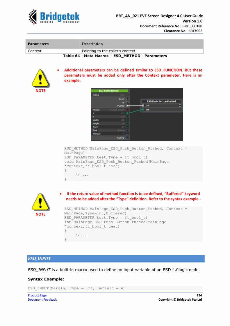
BRT_AN_021 EVE Screen Designer 4.0 User Guide Version 1.0 Document Reference No.: BRT_000180
Clearance No.: BRT#098
Product Page 124
Document Feedback Copyright © Bridgetek Pte Ltd
Parameters Description
Context Pointing to the caller’s context
Table 64 - Meta Macros – ESD_METHOD - Parameters
NOTE
Additional parameters can be defined similar to ESD_FUNCTION. But these parameters must be added only after the Context parameter. Here is an example:
ESD_METHOD(MainPage_ESD_Push_Button_Pushed, Context =
MainPage)
ESD_PARAMETER(test,Type = ft_bool_t)
void MainPage_ESD_Push_Button_Pushed(MainPage
*context,ft_bool_t test)
{
// ...
}
NOTE
If the return value of method function is to be defined, “Buffered” keyword needs to be added after the “Type” definition. Refer to the syntax example -
ESD_METHOD(MainPage_ESD_Push_Button_Pushed, Context =
MainPage,Type=int,Buffered)
ESD_PARAMETER(test,Type = ft_bool_t)
int MainPage_ESD_Push_Button_Pushed(MainPage
*context,ft_bool_t test)
{
// ...
}
ESD_INPUT
ESD_INPUT is a built-in macro used to define an input variable of an ESD 4.0logic node.
Syntax Example:
ESD_INPUT(Margin, Type = int, Default = 4)
BRT_AN_021 EVE Screen Designer 4.0 User Guide Version 1.0 Document Reference No.: BRT_000180
Clearance No.: BRT#098
Product Page 125
Document Feedback Copyright © Bridgetek Pte Ltd
ESD_OUTPUT
ESD_INPUT is a built-in macro used to define an output variable of an ESD 4.0logic
node.
Syntax Example:
ESD_OUTPUT(FirstPos, Type = int)
ESD_UPDATE
ESD_INPUT macro is used to register a function that is called repeatedly by built-in
“Update” slot. This function shall not have any return value.
Syntax Example:
ESD_UPDATE(Ft_Esd_BitmapPersist)
ESD_PARAMETER(bitmapCell, Type = Ft_Esd_BitmapCell *)
void Ft_Esd_BitmapPersist(Ft_Esd_BitmapCell *bitmapCell);
Parameters:
Users can define their own parameter used by the registered function by using the
ESD_PARAMETER.
Pre-compiler options
Within the ESD 4.0C code simulation engine, the following macros are predefined in
generated source code:
ESD_SIMULATION
FT900_PLATFORM
ESD_SIMULATION
ESD_SIMULATION macro is defined when the code is running through the ESD
simulation engine. If some part of the user’s C source code is not supposed to be run
under the ESD simulation engine, for example, accessing some hardware specific
registers, users may choose to skip the code by using this macro.
FT900_PLATFORM
FT900_PLATFORM macro is defined when the target platform is FT90X based. It can be
set when the ESD_SIMULATION macro is defined.

BRT_AN_021 EVE Screen Designer 4.0 User Guide Version 1.0 Document Reference No.: BRT_000180
Clearance No.: BRT#098
Product Page 126
Document Feedback Copyright © Bridgetek Pte Ltd
Add User Functions
Users can define their own functions by writing the C source code directly. If these
functions are defined by using the predefined “ESD_FUNCTION”, they will be shown
under the “User Functions” category in the library browser. Users can drag and drop
these nodes into the logic node editor to use them.
Creating Source File
To add user functions, users need to create a
C source file by clicking File → New →
Source Files.
Upon adding the source file, include the following header (mandatory) in the source
file.
#include "Ft_Esd.h"
Editing the Source File
To make ESD responsive of the user functions, the ESD specific macro “ESD_FUNCTION
or ESD_METHOD” need to be added before the function definition. Refer to the examples
given below –
Syntax Example:
Without parameter input and return value
ESD_FUNCTION(BulbPage_TestFunc)
void BulbPage_TestFunc(){}
Without parameter input, but with the return value
ESD_FUNCTION(Ft_Esd_Theme_GetCurrent, Type = Ft_Esd_Theme *)
Ft_Esd_Theme *Ft_Esd_Theme_GetCurrent();

BRT_AN_021 EVE Screen Designer 4.0 User Guide Version 1.0 Document Reference No.: BRT_000180
Clearance No.: BRT#098
Product Page 127
Document Feedback Copyright © Bridgetek Pte Ltd
Without return value defined, but with the parameter input
ESD_FUNCTION(Ft_Esd_Theme_GetButtonTextColor, Type = ft_rgb32_t)
ESD_PARAMETER(theme, Type = Ft_Esd_Theme *)
ft_rgb32_t Ft_Esd_Theme_GetButtonTextColor(Ft_Esd_Theme *theme) { //.. }
Without return value and parameter input
ESD_FUNCTION(Ft_Esd_Theme_GetButtonTextColor, Type = ft_rgb32_t)
ESD_PARAMETER(theme, Type = Ft_Esd_Theme *)
ft_rgb32_t Ft_Esd_Theme_GetButtonTextColor(Ft_Esd_Theme *theme)
{
//..
}

BRT_AN_021 EVE Screen Designer 4.0 User Guide Version 1.0 Document Reference No.: BRT_000180
Clearance No.: BRT#098
Product Page 128
Document Feedback Copyright © Bridgetek Pte Ltd
Appendix A – List of Figures Figure 1 - Screen Designer - System Error ........................................................................... 13 Figure 2 - ESD 4.0 Nodes Hierarchy .................................................................................... 19 Figure 3 - Making Value Specific to Current Target ................................................................ 24 Figure 4 - Removing Target Specific Value ........................................................................... 25 Figure 5 - EVE Screen Designer 4.0 User Interface Components.............................................. 26 Figure 6 – Menu bar .......................................................................................................... 27 Figure 7 - Toolbar ............................................................................................................. 29 Figure 8 - Project Explorer window ...................................................................................... 30 Figure 9 - Screen Layout Editor – App.main ......................................................................... 31 Figure 10 - Screen Layout Editor - MainPage.c (C Source Code) .............................................. 31 Figure 11 - Logic Node Editor ............................................................................................. 32 Figure 12 - Library Browser ................................................................................................ 32 Figure 13 - Error List Window ............................................................................................. 33 Figure 14 - Output Window ................................................................................................ 34 Figure 15 - Property Editor (ESD Push Button) ...................................................................... 34 Figure 16 - Status bar ....................................................................................................... 35 Figure 17 - Application Project Structure .............................................................................. 36 Figure 18 - Application Workflow ......................................................................................... 37 Figure 19 - Property Editor ................................................................................................. 39 Figure 20 – Switch Page .................................................................................................... 43 Figure 21 - Sample Switch Page UI ..................................................................................... 44 Figure 22 - Properties Editor – Page Allocation ...................................................................... 44 Figure 23 - Sample Source File ........................................................................................... 45 Figure 24 - Zoom In & Out ................................................................................................. 46 Figure 25 - Main File .......................................................................................................... 46 Figure 26 – Sample Logic File ............................................................................................. 47 Figure 27 - C File / C Editor ................................................................................................ 47 Figure 28 – Logic Node Editor - Basic Logic Node .................................................................. 48 Figure 29 - Library Browser - Basic Logic Nodes .................................................................... 48 Figure 30 - Composite Logic Node ....................................................................................... 49 Figure 31 - Composite Logic Node - Page Node ..................................................................... 49 Figure 32 - Logic Node Editor – Widget Node ........................................................................ 50 Figure 33 - User Widget - Position & Size Properties .............................................................. 51 Figure 34 - Layout Widgets ................................................................................................ 52 Figure 35 - Layout Widgets ................................................................................................ 53 Figure 36 - Actor Node ...................................................................................................... 53 Figure 37 - Logic Object ..................................................................................................... 54 Figure 38 - Rendering Order Example .................................................................................. 55 Figure 39 - Library Browser ................................................................................................ 57 Figure 40 - ESD Elements .................................................................................................. 65 Figure 41 - ESD Circle Element ........................................................................................... 65 Figure 42 - ESD Panel Element ........................................................................................... 66 Figure 43 - ESD Gradient Panel Element .............................................................................. 66 Figure 44 - ESD 4.0Primitives ............................................................................................. 67 Figure 45 - ESD Bitmap Primitive ........................................................................................ 67 Figure 46 - ESD Line ......................................................................................................... 69 Figure 47 - ESD Rectangle ................................................................................................. 70 Figure 48 - ESD Display List ............................................................................................... 70 Figure 49 - Library Browser - ESD Theme ............................................................................ 71

BRT_AN_021 EVE Screen Designer 4.0 User Guide Version 1.0 Document Reference No.: BRT_000180
Clearance No.: BRT#098
Product Page 129
Document Feedback Copyright © Bridgetek Pte Ltd
Figure 50 - ESD 4.0 Built-in Themes .................................................................................... 71 Figure 51 – Widgets .......................................................................................................... 74 Figure 52 - ESD Line Widget ............................................................................................... 75 Figure 53 - ESD Circle Widgets ........................................................................................... 75 Figure 54 - ESD Panel Widgets ........................................................................................... 76 Figure 55 - ESD Gradient Widget ........................................................................................ 77 Figure 56 - ESD Check Box Widget ...................................................................................... 78 Figure 57 - ESD Clock Widget ............................................................................................. 78 Figure 58 - ESD Clock Widget Example ................................................................................ 79 Figure 59 - ESD Color Picker Widget .................................................................................... 80 Figure 60 - ESD Color Picker Widget Example ....................................................................... 81 Figure 61 - ESD Gauge Widget ........................................................................................... 81 Figure 62 - ESD Gauge Example ......................................................................................... 82 Figure 63 - ESD Gauge Logic Node Connection Example ........................................................ 82 Figure 64 - ESD Image Widget ........................................................................................... 82 Figure 65 - ESD Image Button ............................................................................................ 83 Figure 66 - ESD Image Button Example ............................................................................... 84 Figure 67 - ESD Image Widget ........................................................................................... 84 Figure 68 - ESD Label ........................................................................................................ 85 Figure 69 - ESD Numeric Label ........................................................................................... 86 Figure 70 - ESD Fixed Point Label ....................................................................................... 87 Figure 71 - ESD Label Button ............................................................................................. 88 Figure 72 - ESD Label Button Example ................................................................................. 89 Figure 73 - ESD Radio Button & ESD Radio Group ................................................................. 89 Figure 74 - ESD Radio Button & ESD Radio Group Example .................................................... 90 Figure 75 - ESD Push Button .............................................................................................. 91 Figure 76 - ESD Push Button Example ................................................................................. 92 Figure 77 - ESD Progress Bar ............................................................................................. 92 Figure 78 - ESD Progress Bar Example ................................................................................ 93 Figure 79 - ESD Slider Widget ............................................................................................ 93 Figure 80 - ESD Slider Example .......................................................................................... 94 Figure 81 - ESD Slider Logic Node Connection Example ......................................................... 94 Figure 82 - ESD Scroll Bar Widget ....................................................................................... 95 Figure 83 - ESD Scroll Panel ............................................................................................... 96 Figure 84 - ESD Scrollable Image ........................................................................................ 97 Figure 85 – Touch Control Mode Runtime ............................................................................. 98 Figure 86 – Touch Control Mode Design ............................................................................... 98 Figure 87 - Slide Control Mode Runtime .............................................................................. 99 Figure 88 – Slide Control Mode Design ................................................................................. 99 Figure 89 - ESD Sketch Widget .......................................................................................... 100 Figure 90 - ESD Spin Box .................................................................................................. 101 Figure 91 - ESD Spin Box Example ..................................................................................... 102 Figure 92 - ESD Toggle ..................................................................................................... 103 Figure 93 - ESD Toggle Widget Example ............................................................................. 104 Figure 94 - Logic Flow ...................................................................................................... 104 Figure 95 - Logic Flow – Condition Node ............................................................................. 105 Figure 96 - Logic Flow – Binary Condition Node.................................................................... 105 Figure 97 - Logic Flow - Binary Operator Node ..................................................................... 106 Figure 98 - Logic Flow - Ternary Operator Node ................................................................... 107 Figure 99 - Logic Flow - Unary Operator Node ..................................................................... 107 Figure 100 - Logic Flow – Sequence Node ........................................................................... 108 Figure 101 - Logic Flow – Switch Node ................................................................................ 108

BRT_AN_021 EVE Screen Designer 4.0 User Guide Version 1.0 Document Reference No.: BRT_000180
Clearance No.: BRT#098
Product Page 130
Document Feedback Copyright © Bridgetek Pte Ltd
Figure 102 - Logic Flow – Switch Value ............................................................................... 109 Figure 103 - Logic Flow - Set Variable Node ........................................................................ 109 Figure 104 - Logic Interface .............................................................................................. 111 Figure 105 - Logic Interface - Input Node ........................................................................... 111 Figure 106 - Logic Interface - Output Node ......................................................................... 112 Figure 107 - Logic Interface - Signal Node .......................................................................... 112 Figure 108 - Logic Interface - Slot Node .............................................................................. 113 Figure 109 - Logic Interface - Variable Node ........................................................................ 114 Figure 110 - Logic Interface - Writer Node .......................................................................... 114 Figure 111 - Property Editor .............................................................................................. 117 Figure 112 - ESD Common Properties ................................................................................. 117 Figure 113 – Name Property .............................................................................................. 118 Figure 114 – Depth Sort Property ....................................................................................... 118 Figure 115 – Right Click Menu ........................................................................................... 118 Figure 116 – Active Property ............................................................................................. 119 Figure 117 – User Functions Example ................................................................................. 122 Figure 118 – ESD_METHOD Example .................................................................................. 123
Appendix B – List of Tables Table 1 - Installation Folder ................................................................................................ 18 Table 2 - Menu & Description .............................................................................................. 29 Table 3 - Toolbar & Description ........................................................................................... 30 Table 4 - ESD 4.0 Libraries ................................................................................................. 33 Table 5 - Bitmap Resource Properties .................................................................................. 40 Table 6 - Connection End Types .......................................................................................... 54 Table 7 – Switch Page Layout Properties .............................................................................. 58 Table 8 – Fixed Positioning Layout Properties ....................................................................... 59 Table 9 – Fill Layout Properties ........................................................................................... 60 Table 10 – Linear Layout Properties..................................................................................... 61 Table 11 – Stretch Layout Properties ................................................................................... 63 Table 12 – Scroll Layout Properties ..................................................................................... 64 Table 13 - ESD Circle Element Properties ............................................................................. 65 Table 14 - ESD Panel Element Properties ............................................................................. 66 Table 15 - ESD Gradient Panel Element Properties ................................................................ 66 Table 16 - ESD Bitmap Properties ....................................................................................... 67 Table 17 - ESD Line Properties ........................................................................................... 69 Table 18 - ESD Rectangle Properties.................................................................................... 70 Table 19 - Ft_Esd_Theme_LightBlue Theme ........................................................................ 72 Table 20 - Ft_Esd_Theme_DarkOrange Theme ..................................................................... 72 Table 21 – ESD Utilities & Description .................................................................................. 74 Table 22 - ESD Line Widget Properties ................................................................................. 75 Table 23 - ESD Circle Element Properties ............................................................................. 76 Table 24 - ESD Panel Widget Properties ............................................................................... 76 Table 25 - ESD Panel Raised and Sunken Widget Properties ................................................... 77 Table 26 - ESD Gradient Widget Properties........................................................................... 77 Table 27 - ESD Check Box Widget Properties ........................................................................ 78 Table 28 - ESD Clock Widget Properties ............................................................................... 79 Table 29 - ESD Color Picker Widget Properties ...................................................................... 80

BRT_AN_021 EVE Screen Designer 4.0 User Guide Version 1.0 Document Reference No.: BRT_000180
Clearance No.: BRT#098
Product Page 131
Document Feedback Copyright © Bridgetek Pte Ltd
Table 30 - ESD Color Picker Widget Output/Signal................................................................. 80 Table 31 - ESD Gauge Widget Properties .............................................................................. 81 Table 32 - ESD Image Properties ........................................................................................ 83 Table 33 - ESD Image Button Properties .............................................................................. 83 Table 34 - ESD Image Button Output/Signal ......................................................................... 84 Table 35 - ESD Image Properties ........................................................................................ 85 Table 36 - ESD Label Properties .......................................................................................... 86 Table 37 - ESD Numeric Label Properties ............................................................................. 87 Table 38 - ESD Fixed Point Label Properties.......................................................................... 87 Table 39 - ESD Label Button Properties ................................................................................ 88 Table 40 - ESD Radio Button Properties ............................................................................... 90 Table 41 - ESD Push Button Properties ................................................................................ 91 Table 42 - ESD Push Button Output/Signal ........................................................................... 91 Table 43 - ESD Progress Bar Properties ............................................................................... 93 Table 44 - ESD Slider Widget Properties ............................................................................... 94 Table 45 - ESD Slider Output/Signal .................................................................................... 94 Table 46 - ESD Scroll Bar Widget Properties ......................................................................... 95 Table 47 - ESD Scroll Bar Output/Signal .............................................................................. 95 Table 48 - ESD Scroll Panel Widget Properties ...................................................................... 96 Table 49 - ESD Scroll Panel Output/Signal ............................................................................ 97 Table 50 - ESD Scroll Panel Widget Properties ...................................................................... 98 Table 51 - ESD Scrollable Image Output/Signal .................................................................... 98 Table 52 - ESD Sketch Widget Properties ............................................................................ 101 Table 53 - ESD Sketch Widget Output/Signal ....................................................................... 101 Table 54 - ESD Spin Box Properties .................................................................................... 102 Table 55 - ESD Spin Box Output/Signal .............................................................................. 102 Table 56 - ESD Toggle Widget Properties ............................................................................ 103 Table 57 - ESD Toggle Widget Output/Signal ....................................................................... 103 Table 58 - Binary Operators Supported by ESD 4.0 .............................................................. 106 Table 59 – Unary Operators Supported by ESD 4.0 .............................................................. 107 Table 60 - Built-in Slots .................................................................................................... 113 Table 61 – Widget Interface Properties ............................................................................... 116 Table 62 - Macros – ESD_TYPE - Parameters ....................................................................... 121 Table 63 - Macros – ESD_FUNCTION - Parameters ............................................................... 122 Table 64 - Meta Macros – ESD_METHOD - Parameters .......................................................... 124

BRT_AN_021 EVE Screen Designer 4.0 User Guide Version 1.0 Document Reference No.: BRT_000180
Clearance No.: BRT#098
Product Page 132
Document Feedback Copyright © Bridgetek Pte Ltd
Appendix C – Revision History
Document Title : BRT_AN_021 EVE Screen Designer 4.0 User Guide
Document Reference No. : BRT_000180
Clearance No. : BRT#098
Product Page : http://brtchip.com/eve
Document Feedback : Send Feedback
Revision Changes Date
Version 1.0 Initial Release 2017-10-19