everest xv tech corp gb 1 · pdf file• pre-lacquered steel exterior finish (ral 9006 dark...
TRANSCRIPT

READYErP
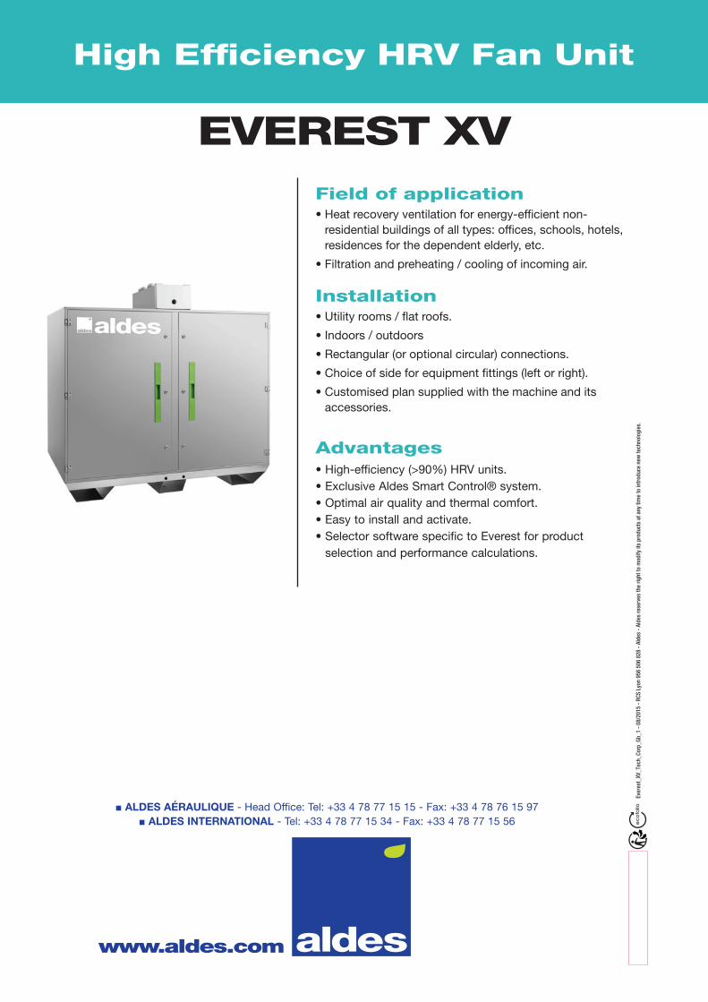
High Efficiency HRV Fan Unit
Everest XV
Field of application
Installation
Advantages
Description
Range
Technical details
Aeraulic and electrical details
Acoustic specifications
Aldes Smart Control® system
Servicing
Options & Accessories

2
READYErP
High Efficiency HRV Fan Unit
Everest XV
FIELD OF APPLICATION• Heat recovery ventilation for energy-efficient non-
residential buildings of all types: offices, schools, hotels, residences for the dependent elderly, etc.
• Filtration and preheating / cooling of incoming air.
INSTALLATION• Utility rooms / flat roofs.• Indoors / outdoors• Rectangular (or optional circular) connections.• Choice of side for equipment fittings (left or right).• Customised plan supplied with the machine and its
accessories.
DESCRIPTION• 4 Everest models up to 2,300 m3/h.• Pre-cabled monoblock units.• Self-supporting construction with dual-wall panels.• 50 mm mineral wool insulation.• Access to all components via hinged doors on
the front, and to the control system via its own dedicated central hatch.
• Aluminium or galvanised steel + paint coating condensate collection tray.
• Factory-mounted single-piece cowl for outdoor versions.
• Pre-lacquered steel exterior finish (RAL 9006 dark grey).
• M0 galvanised steel Z275 interior finishes.• High efficiency counterflow plate heat exchanger (up
to 90 % and more). • EC motor with backward curved impeller.• Adjustable 100 % bypass.• G4 flat filters on exhaust air and F7 on fresh air.• Built-in switch.• Aldes Smart Control® system: - Constant speed.- Constant airflow.- Constant pressure.• Airflow control using CO2/VOC sensor (0-10V
signal). - Controlled pressure.- Built-in clock: operating hours can be controlled
with timer.• Configuration & monitoring via: - Hard-wired remote control.- Built-in webserver.- BMS communication via ModbusTRU, Bacnet, TCP/
IP and LON (optional) protocols.• Smart frost protection via controlled opening of the
bypass.
UNIT CUSTOMISATIONConfigurable components
Additional options (delivered within the unit)
Advantages• High-efficiency (>90%) HRV units.• Exclusive Aldes Smart Control® system.• Optimal air quality and thermal comfort.• Easy to install and activate.• Selector software specific to Everest for product
selection and performance calculations.
Access panel Left or Right hand side
Version Interior or exterior (leak-tight factory-fitted single-block roofing element).
Control mode
Variable speedor
Constant airflowor
Constant pressureor
Variable airflow controlled by CO2/VOC sensor(0-10V signal)
orControlled pressure
orAirflow adjusted via 0-10V signal
Filters
Fresh air supply filter: F7 50 mm flat mini-fold filter as standard or F7 HE 100 mm mini-fold
low-pressure loss filter as option. Optional G4 pre-filter. Exhaust air filter: G4 as standard, F7
flat 50 mm mini-fold as an option.
Internal coils
Electrical heating coilor Hot water coil
or Cold water coil*or Reversible coil*
Heat-exchanger frost protection Electrical coil (frost protection via controlled opening of the standard bypass).
Communications system LON (Modbus, TCP/IP, BACnet as standard)
Filter clogging alarm Differential pressure sensor(measures pressure loss in real time)
Conformity• EUROVENT certified air-air heat exchanger
system (based on the AAHE heat exchanger programme).
• CE compliant.• Compliant with 2016 and 2018 ErP
regulations
* available starting on 1st October 2015

3
EVEREST XV 2300
EVEREST XV 1600
EVEREST XV 1200
EVEREST XV 600
Q (m3/h)
0 500 1000 1500 2000 2500
High Efficiency HRV Fan Unit
RANGE
ACCESSORIES SPARE FILTER KIT
Designation CodeEverest XV 600 11069010Everest XV 1200 11069011Everest XV 1600 11069012Everest XV 2300 11069013
Designation CodeEverest XV 600 motorised damper 11068452Everest XV 1200 motorised damper 11068451Everest XV 1600 motorised damper 11068450Everest XV 2300 motorised damper 11069018Everest XV 600 standard flexible sleeve 11068417Everest XV 1200 standard flexible sleeve 11068416Everest XV 1600 standard flexible sleeve 11068415Everest XV 2300 standard flexible sleeve 11068414Everest XV 600 insulated flexible sleeve 11068349Everest XV 1200 insulated flexible sleeve 11068348Everest XV 1600 insulated flexible sleeve 11068347Everest XV 2300 insulated flexible sleeve 11068346Everest XV 600 rigid adapter piece 11068431Everest XV 1200 rigid adapter piece 11068386Everest XV 1600 rigid adapter piece 11068385Everest XV 2300 rigid adapter piece 11068384
Designation CodeEverest XV 600 F7 flat filter kit 11068458Everest XV 1200 F7 flat filter kit 11068458 (x2)Everest XV 1600 F7 flat filter kit 11069350Everest XV 2300 F7 flat filter kit 11069354Everest XV 600 G4 filter kit 11068459Everest XV 1200 G4 filter kit 11068459 (x2)Everest XV 1600 G4 filter kit 11069349Everest XV 2300 G4 filter kit 11069353Everest XV 600 F7 HE filter kit 11068457Everest XV 1200 F7 HE filter kit 11068457 (x2)Everest XV 1600 F7 HE filter kit 11068456Everest XV 2300 F7 HE filter kit 11068455
4
570
435
389
1200
1260
190134
840
685
638
1200
1260
190134
Everest XV 600
Everest XV 1200
High Efficiency HRV Fan Unit
Model Height (mm)
Depth (mm)
Length (mm)
Branchconnection size
(mm)
Connector size(mm)
Weight (kg)
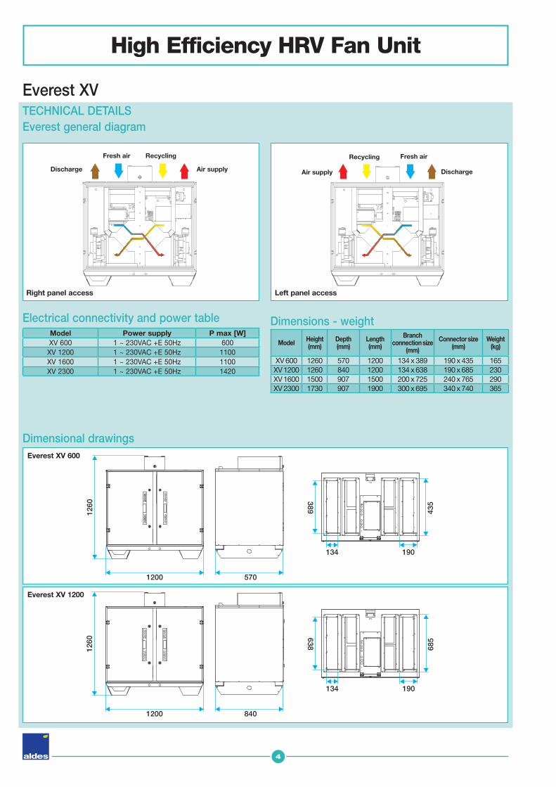
XV 600 1260 570 1200 134 x 389 190 x 435 165XV 1200 1260 840 1200 134 x 638 190 x 685 230XV 1600 1500 907 1500 200 x 725 240 x 765 290XV 2300 1730 907 1900 300 x 695 340 x 740 365
Everest XV TECHNICAL DETAILSEverest general diagram
Dimensions - weightElectrical connectivity and power table
Dimensional drawings
Model Power supply P max [W]XV 600 1 ~ 230VAC +E 50Hz 600
XV 1200 1 ~ 230VAC +E 50Hz 1100XV 1600 1 ~ 230VAC +E 50Hz 1100XV 2300 1 ~ 230VAC +E 50Hz 1420
Fresh air
Discharge
Recycling
Air supply Discharge
Fresh airRecycling
Air supply
Right panel access Left panel access

5
1500
1500
200
907
240
765725
700
700
1730
1900
300
907
340
740695
Everest XV 1600
Everest XV 2300
Dimensional drawings
High Efficiency HRV Fan Unit
Everest XV
ModelNominal airflow (m3/h)
Power absorbed (W)
Pressure
Pa
XV 600 600 500 200XV 1200 1200 780 200XV 1600 1600 1011 200XV 2300 2300 1400 250
Clearance required for maintenanceAll components are accessible via the front panel, regardless of model. Therefore, the Everest unit can be placed against a wall or back-to-back with another unit.
AERAULIC AND ELECTRICAL DETAILS Table of rated flow rates and pressures
MOTOR DETAILS- Single phase motor for models 1,000 to 3,500 m3/h (230 V AC +E) or
3-phase for models from 4,500 to 7,000 m3/h (400 V AC +N +E) - Integrated thermal protection. IP54 Class F, controlled by 0-10V signal
Model Impeller Max. fan power (kW)
Imax per fan (A) 1~200…277V
or 3~380...480V
XV 600 Ø225 00:24 1.7-1.25XV 1200 Ø250 0.45 2.2-1.65XV 1600 Ø250 0.49 2.6-1.85XV 2300 Ø310 0.7 3.65-2.7

6
Q (m3/h)
P (P
a)
Q (m3/h)
700
800
600
500
400
100
200
300
200100 300 400 500 600 7000
200100 300 400 500 600 7000
150
200
400
250
300
350
500
450
50
100
P (W
)
P (P
a)P
(W)
Q (m3/h)
400200 600 800 1000 1200 1400 1600 18000
300
400
800
500
600
700
1000
900
100
200
Q (m3/h)
400200 600 800 1000 1200 1400 1600 18000
300
400
800
500
600
700
1000
900
100
200
P (P
a)
Q (m3/h)
400200 600 800 1000 1200 14000
300
400
800
500
600
700
1000
900
100
200
P (W
)
Q (m3/h)
400200 600 800 1000 1200 14000
300
400
800
500
600
700
1000
900
100
200
Q (m3/h)
P (P
a)
700
800
600
500
400
100
200
300
500 1000 1500 2000 25000
P (W
)
Q (m3/h)
500 1000 1500 2000 25000
1400
1600
1200
1000
800
200
400
600
Everest XV 600
Everest XV 1600
Everest XV 1200
Everest XV 2300
High Efficiency HRV Fan Unit
Curves obtained using French standard NF EN ISO 5801P (Pa) = static pressure P (W) = power consumption.
AERAULIC AND ELECTRICAL CURVES
Model Pressure Max. airflow Min. airflow Reserved at max. airflowXV 600 200 650 90 18%XV 1200 200 1200 200 5%XV 1600 200 1650 250 10%XV 2300 300 2500 300 8%
Everest XV
Airflow range

7
High Efficiency HRV Fan Unit
Everest XV ACOUSTIC DETAILSCriteria complying with standards:- ISO 5136 sound levels in ducts- ISO 3741 radiated sound
Lwc asp: sound power in ducts during aspirationLwc dis: sound power in duct during air supplyLp - dB(A): sound pressure radiated at 4 m from connected casing.
Frequency (Hz) 63 125 250 500 1000 2000 4000 8000 Global (dB(A))
Everest XV 600 (450 m3/h - 200 Pa)Lwc asp - dB 58 68 70 72 69 61 63 62 77Lwc sup - dB 69 67 71 71 69 66 60 55 77Lp - dB(A) 23 13 13 19 20 17 <10 <10 27
Everest XV 1200 (1100 m3/h - 200 Pa)Lwc asp - dB 65 71 70 71 70 65 67 71 78Lwc sup - dB 72 72 72 71 72 72 66 64 80Lp - dB(A) 25 17 14 18 23 22 13 <10 29
Everest XV 1600 (1500m3/h - 200 Pa)Lwc asp - dB 56 65 67 71 70 66 68 69 77Lwc sup - dB 69 68 71 73 74 71 67 63 79Lp - dB(A) 22 12 13 20 25 22 13 <10 29
Everest XV 2300 (2100m3/h - 200 Pa)Lwc asp - dB 55 64 71 70 67 65 67 68 77Lwc sup - dB 68 67 73 72 73 71 67 65 80Lp - dB(A) 21 12 16 19 24 22 14 <10 29
8
High Efficiency HRV Fan Unit
CONDENSATE CHARACTERISTICS
Everest XV
Control function Designation MenuUser
Advanced menuSecure access
Expert* menuSecure access
Functions for optimum air quality
Fan control mode
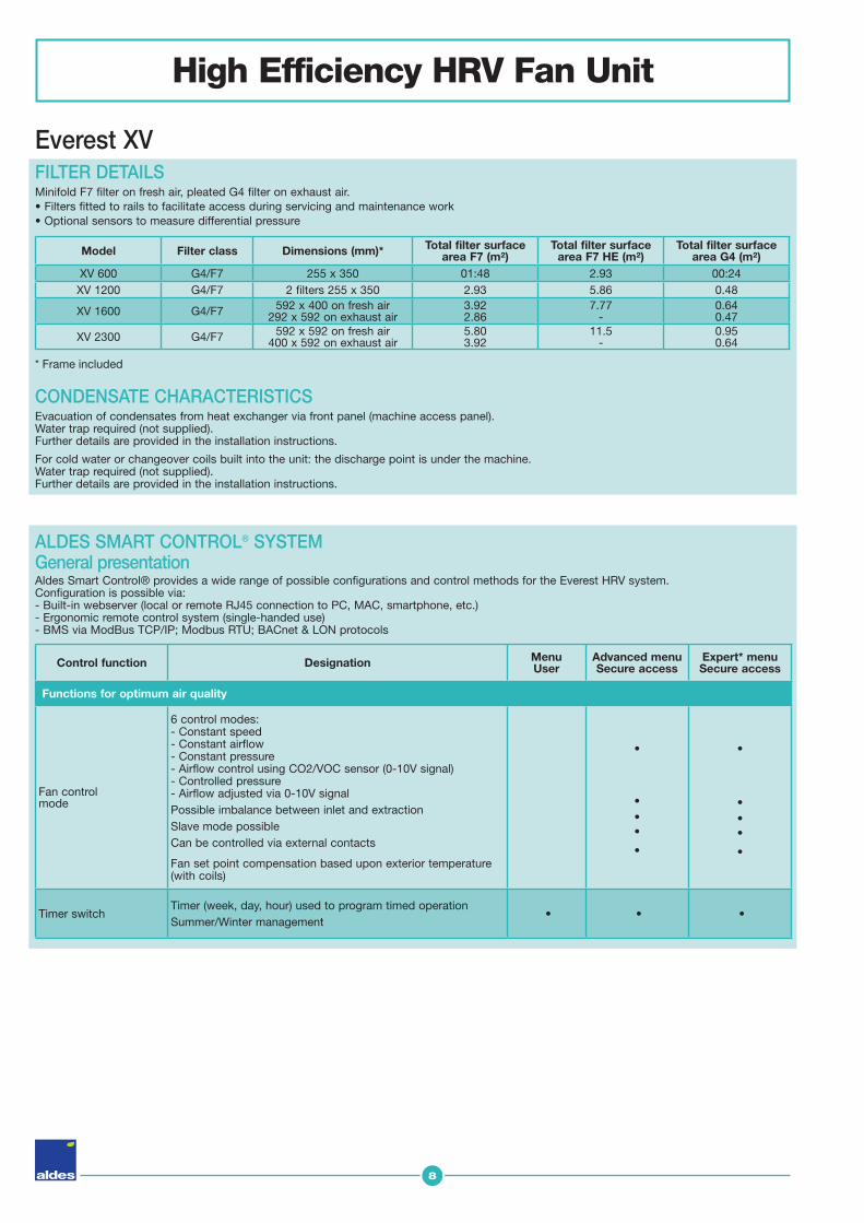
6 control modes:- Constant speed- Constant airflow- Constant pressure- Airflow control using CO2/VOC sensor (0-10V signal)- Controlled pressure- Airflow adjusted via 0-10V signalPossible imbalance between inlet and extractionSlave mode possibleCan be controlled via external contacts
Fan set point compensation based upon exterior temperature (with coils)
•
•••
•
•
•••
•
Timer switchTimer (week, day, hour) used to program timed operationSummer/Winter management
• • •
Evacuation of condensates from heat exchanger via front panel (machine access panel).Water trap required (not supplied).Further details are provided in the installation instructions.
For cold water or changeover coils built into the unit: the discharge point is under the machine.Water trap required (not supplied).Further details are provided in the installation instructions.
Aldes Smart Control® provides a wide range of possible configurations and control methods for the Everest HRV system.Configuration is possible via:- Built-in webserver (local or remote RJ45 connection to PC, MAC, smartphone, etc.)- Ergonomic remote control system (single-handed use)- BMS via ModBus TCP/IP; Modbus RTU; BACnet & LON protocols
General presentation
Model Filter class Dimensions (mm)* Total filter surface area F7 (m²)
Total filter surface area F7 HE (m²)
Total filter surface area G4 (m²)
XV 600 G4/F7 255 x 350 01:48 2.93 00:24XV 1200 G4/F7 2 filters 255 x 350 2.93 5.86 0.48
XV 1600 G4/F7 592 x 400 on fresh air292 x 592 on exhaust air
3.922.86
7.77-
0.640.47
XV 2300 G4/F7 592 x 592 on fresh air400 x 592 on exhaust air
5.803.92
11.5-
0.950.64
FILTER DETAILS Minifold F7 filter on fresh air, pleated G4 filter on exhaust air.• Filters fitted to rails to facilitate access during servicing and maintenance work• Optional sensors to measure differential pressure
* Frame included
ALDES SMART CONTROL® SYSTEM

9
High Efficiency HRV Fan Unit
Functionalities designed to provide optimal thermal comfort.
Temperature control
3 temperature control methods - T°C constant - air supply - T°C constant - exhaust air - Constant difference between air supply/exhaustPossible to change controlled temperature during switch from summer to winter mode (and vice versa).
•
•
•
•
Bypass controlCooling via automatic opening of the bypass according to outdoor conditions (Free cooling) - Night cooling function
• •
Heat exchanger frost protection
Frost protection by controlling the opening of the bypassSmart frost protection by controlling the opening of the bypass + electrical coil
•
•
•
•
Damper adjustmentDamper controlClosed when stopped
• •
Coil control
Coil controlFrost-protection and water coil protection Temperature set point compensation based on outdoor temperature (with coils)
•
•
Unit monitoring functions
Alarms
Types- Multiple configurable alarms
(including a fire alarm using an external contact, filter clogged alarm, etc.)
- Alarm forwarding by e-mail Display - Current active alarms- Display of future alarms- Alarm log
•
•
•
•
•
•
Verification of operational status
- Real-time data on component status (filter pressure loss, etc.)- Operational data log- Data update/backup using SD cards - Override mode for components operational tests
•
•
•
••
•
•
••
•
InstallationAftersales service
- Unit can be reconfigured on-site: reassignment of I/Os;
- Reset to factory settings- Advanced settings available for each component
••
•
••
Everest XV
* Expert menu - only accessible via the webserver.
Control function Designation MenuUser
Advanced menuSecure access
Expert* menuSecure access
10
High Efficiency HRV Fan Unit
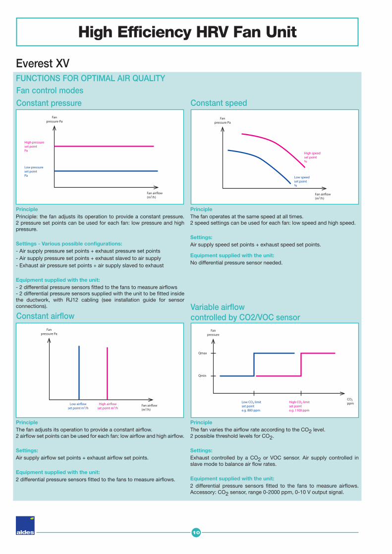
PrinciplePrinciple: the fan adjusts its operation to provide a constant pressure. 2 pressure set points can be used for each fan: low pressure and high pressure.
Settings - Various possible confi gurations:- Air supply pressure set points + exhaust pressure set points - Air supply pressure set points + exhaust slaved to air supply - Exhaust air pressure set points + air supply slaved to exhaust
Equipment supplied with the unit: - 2 differential pressure sensors fi tted to the fans to measure airfl ows - 2 differential pressure sensors supplied with the unit to be fi tted inside the ductwork, with RJ12 cabling (see installation guide for sensor connections).
PrincipleThe fan adjusts its operation to provide a constant airfl ow. 2 airfl ow set points can be used for each fan: low airfl ow and high airfl ow.
Settings:Air supply airfl ow set points + exhaust airfl ow set points.
Equipment supplied with the unit: 2 differential pressure sensors fi tted to the fans to measure airfl ows.
PrincipleThe fan operates at the same speed at all times. 2 speed settings can be used for each fan: low speed and high speed.
Settings:Air supply speed set points + exhaust speed set points.
Equipment supplied with the unit: No differential pressure sensor needed.
PrincipleThe fan varies the airfl ow rate according to the CO2 level. 2 possible threshold levels for CO2.
Settings:Exhaust controlled by a CO2 or VOC sensor. Air supply controlled in slave mode to balance air fl ow rates.
Equipment supplied with the unit:2 differential pressure sensors fi tted to the fans to measure airfl ows. Accessory: CO2 sensor, range 0-2000 ppm, 0-10 V output signal.
Everest XV
Fan control modes
Constant pressure
Constant airflow
Constant speed
Variable airflowcontrolled by CO2/VOC sensor
Fan air�ow(m3/h)
Fanpressure Pa
High pressureset pointPa
Low pressureset pointPa
Fan air�ow(m3/h)
Fanpressure Pa
High air�owset point m3/h
Low air�owset point m3/h
Fan air�ow(m3/h)
Fanpressure Pa
High speedset point%
Low speedset point%
CO2ppm
Qmax
Qmin
Fanpressure
High CO2 limitset pointe.g. 1100 ppm
Low CO2 limitset pointe.g. 800 ppm
FUNCTIONS FOR OPTIMAL AIR QUALITY

11
High Efficiency HRV Fan Unit
Everest XV
PrincipleFan controlled to ensure pressure increases alongside airfl ow 1 set point per fan. The unit will change the pressure set point to match the measured airfl ow
Settings:Indicate the max. and min. airfl ow rates for each ductwork with their associated pressure losses. E.g. Air supply: Qmax 5000 m3/h Pmax 300 Pa / Air supply:
Qmin 2000 m3/h Pmin 150 Pa Exhaust air Qmax 5000 m3/h Pmax 290 Pa / Exhaust air
Qmin 2000 m3/h Pmin 145 Pa.
Equipment supplied with the unit: - 2 differential pressure sensors fi tted to the fans to measure airfl ow rates - 2 differential pressure sensors supplied with the unit to be fi tted inside the ductwork, with RJ12 cabling (see installation guide for sensor connections inside the ducts).
PrincipleTimed programming of set points:- Low setting, - High setting, - Stop.
Settings:Example of constant airfl ow operation:
Controlled pressure
Weekly programming (possible for all control modes)
Fan control modes
Timer switch
High setting Low setting
Fan air�ow(m3/h)
Set point
Pmax
Pmin
Fanpressure
Pa
QmaxQmin
12
High Efficiency HRV Fan Unit
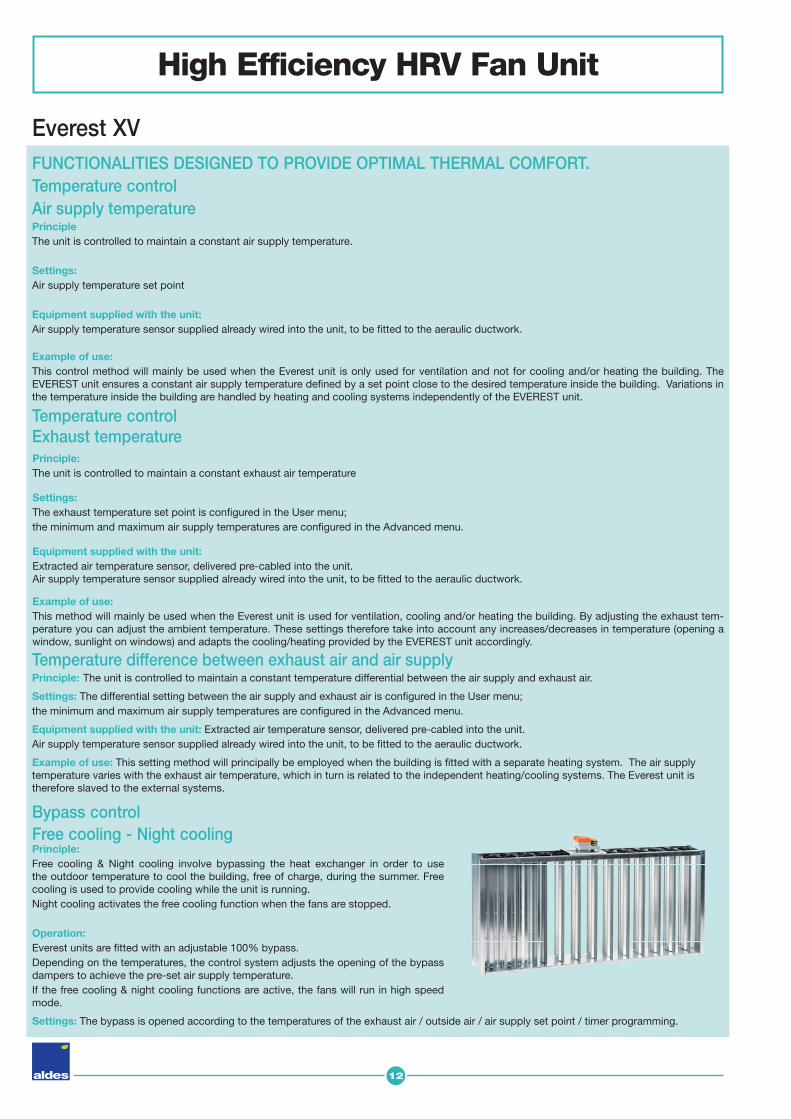
Principle:Free cooling & Night cooling involve bypassing the heat exchanger in order to use the outdoor temperature to cool the building, free of charge, during the summer. Free cooling is used to provide cooling while the unit is running. Night cooling activates the free cooling function when the fans are stopped.
Operation:Everest units are fi tted with an adjustable 100% bypass. Depending on the temperatures, the control system adjusts the opening of the bypass dampers to achieve the pre-set air supply temperature.If the free cooling & night cooling functions are active, the fans will run in high speed mode.
Settings: The bypass is opened according to the temperatures of the exhaust air / outside air / air supply set point / timer programming.
Temperature difference between exhaust air and air supplyPrinciple: The unit is controlled to maintain a constant temperature differential between the air supply and exhaust air.
Settings: The differential setting between the air supply and exhaust air is confi gured in the User menu; the minimum and maximum air supply temperatures are confi gured in the Advanced menu.
Equipment supplied with the unit: Extracted air temperature sensor, delivered pre-cabled into the unit. Air supply temperature sensor supplied already wired into the unit, to be fi tted to the aeraulic ductwork.
Example of use: This setting method will principally be employed when the building is fi tted with a separate heating system. The air supply temperature varies with the exhaust air temperature, which in turn is related to the independent heating/cooling systems. The Everest unit is therefore slaved to the external systems.
Everest XV
Principle:The unit is controlled to maintain a constant exhaust air temperature
Settings:The exhaust temperature set point is confi gured in the User menu; the minimum and maximum air supply temperatures are confi gured in the Advanced menu.
Equipment supplied with the unit:Extracted air temperature sensor, delivered pre-cabled into the unit. Air supply temperature sensor supplied already wired into the unit, to be fi tted to the aeraulic ductwork.
Example of use: This method will mainly be used when the Everest unit is used for ventilation, cooling and/or heating the building. By adjusting the exhaust tem-perature you can adjust the ambient temperature. These settings therefore take into account any increases/decreases in temperature (opening a window, sunlight on windows) and adapts the cooling/heating provided by the EVEREST unit accordingly.
Bypass control Free cooling - Night cooling
Temperature controlExhaust temperature
PrincipleThe unit is controlled to maintain a constant air supply temperature.
Settings:Air supply temperature set point
Equipment supplied with the unit:Air supply temperature sensor supplied already wired into the unit, to be fi tted to the aeraulic ductwork.
Example of use: This control method will mainly be used when the Everest unit is only used for ventilation and not for cooling and/or heating the building. The EVEREST unit ensures a constant air supply temperature defi ned by a set point close to the desired temperature inside the building. Variations in the temperature inside the building are handled by heating and cooling systems independently of the EVEREST unit.
FUNCTIONALITIES DESIGNED TO PROVIDE OPTIMAL THERMAL COMFORT.Temperature controlAir supply temperature
13
High Efficiency HRV Fan Unit
Everest XV
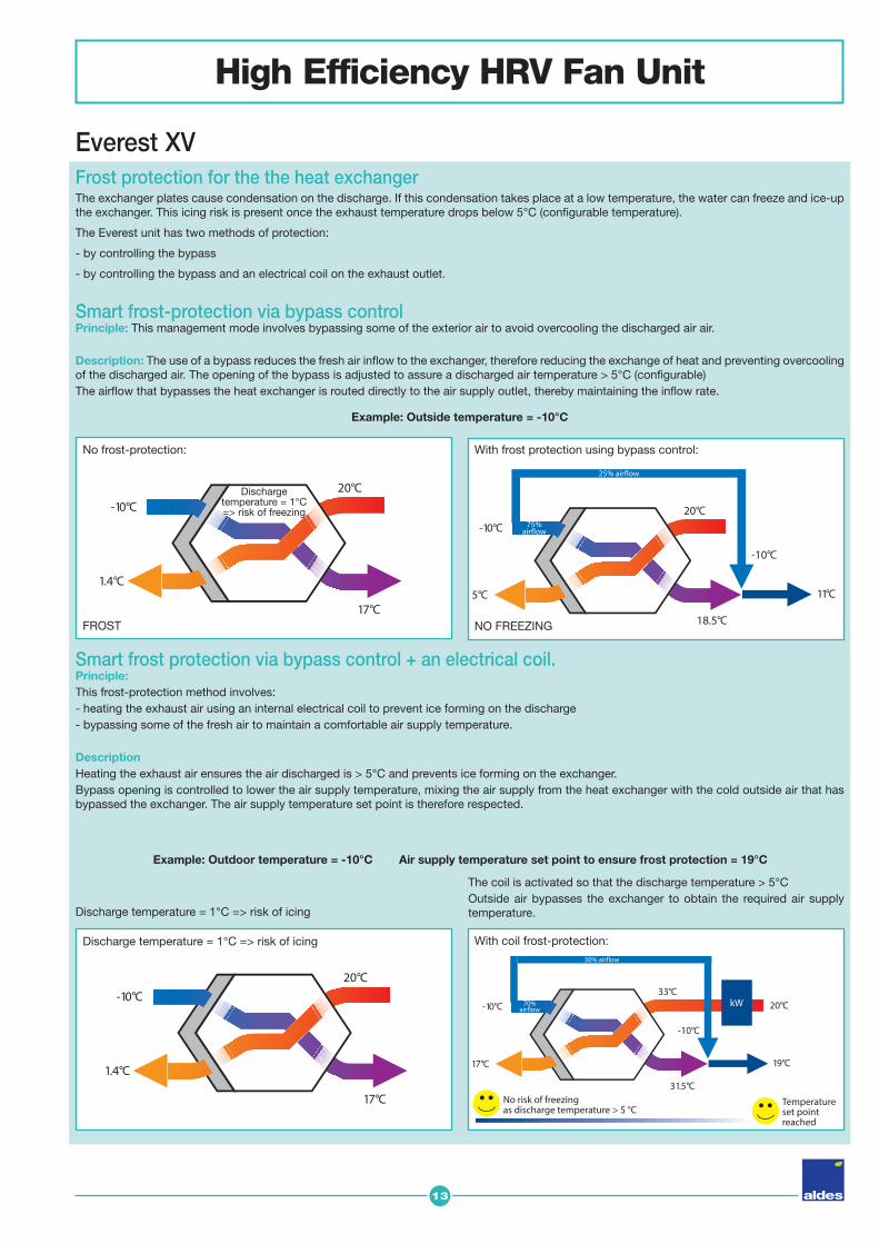
Smart frost-protection via bypass controlPrinciple: This management mode involves bypassing some of the exterior air to avoid overcooling the discharged air air.
Description: The use of a bypass reduces the fresh air infl ow to the exchanger, therefore reducing the exchange of heat and preventing overcooling of the discharged air. The opening of the bypass is adjusted to assure a discharged air temperature > 5°C (confi gurable)The airfl ow that bypasses the heat exchanger is routed directly to the air supply outlet, thereby maintaining the infl ow rate.
Frost protection for the the heat exchangerThe exchanger plates cause condensation on the discharge. If this condensation takes place at a low temperature, the water can freeze and ice-up the exchanger. This icing risk is present once the exhaust temperature drops below 5°C (confi gurable temperature).
The Everest unit has two methods of protection:
- by controlling the bypass
- by controlling the bypass and an electrical coil on the exhaust outlet.
-10°C
17°C
33°C
31.5°C
-10°C
20°C
19°C
kW
30% air�ow
70%air�ow
Temperatureset pointreached
No risk of freezingas discharge temperature > 5 °C
-10°C
1.4°C
20°C
17°C
With coil frost-protection: Discharge temperature = 1°C => risk of icing
Discharge temperature = 1°C => risk of icing
The coil is activated so that the discharge temperature > 5°COutside air bypasses the exchanger to obtain the required air supply temperature.
Smart frost protection via bypass control + an electrical coil.Principle:This frost-protection method involves:- heating the exhaust air using an internal electrical coil to prevent ice forming on the discharge- bypassing some of the fresh air to maintain a comfortable air supply temperature.
Description Heating the exhaust air ensures the air discharged is > 5°C and prevents ice forming on the exchanger.Bypass opening is controlled to lower the air supply temperature, mixing the air supply from the heat exchanger with the cold outside air that has bypassed the exchanger. The air supply temperature set point is therefore respected.
Example: Outdoor temperature = -10°C Air supply temperature set point to ensure frost protection = 19°C
-10°C
1.4°C
20°C
17°C
No frost-protection:
Discharge temperature = 1°C => risk of freezing
FROST
-10°C
5°C
20°C
18.5°C
-10°C
11°C
25% air�ow
75%air�ow
NO FREEZING
With frost protection using bypass control:
Example: Outside temperature = -10°C

14
ModBus
RTU
TCPIP
High Efficiency HRV Fan Unit
Everest XV Damper adjustmentPrinciple:The dampers are used to prevent the circulation of air inside the unit when it is stopped.The dampers are motorised and they operate in conjunction with the fans. The damper servomotor is fi tted with a return spring, allowing the damper to close if there is an electricity blackout.
Coil control Principle:The Aldes Smart Control® system controls the coils directly.
Operation:The electrical coil is activated proportionally by a 0-10V signal transmitted by the control system.
Equipment supplied with the unit:Coil built into the unit, pre-cabled and ready for connection to the power supply.
Water coil Principle:The Aldes Smart Control® system operates the valve.
Operation:The valve is controlled proportionally by a 0-10V signal transmitted by the control system. The water coil is supplied with a temperature sensor to be fi tted into the water return circuit.Depending on the temperature of the returning water, the control system will activate the coil frost-protection function: valve opened to maximum. In the event of an extreme temperature, the control system will shut down the fans.
Equipment supplied with the unit:Coil delivered built into the unit. Valve supplied, circulator and tempera-ture sensor to be cabled and fi tted to the water return circuit.
Communications method
PC Smartphone
Aldes Smart Control®
BMSRemote control
Webserver
UNIT MONITORING FUNCTIONSGeneral information:The Aldes Smart Control® system provides a multitude of possible methods for controlling the unit.
Fire alarmAn external contact is available to set the unit to 'fi re' mode. This enables a dedicated control mode (e.g. unit shutdown), when a fi re alarm is transmitted to the Aldes Smart Control® System.
BackupReset to factory settings.Save to a PC or SD Card, the control parameters used when installing the equipment.
Component status readingsReal-time data on component statusExamples: speed (%) of each fan, set-points, temperature of each sensor, status of dampers, loss of pressure through fi lters, coil states, etc.
15
High Efficiency HRV Fan Unit
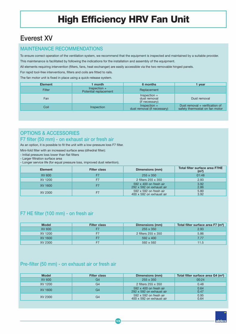
Everest XV MAINTENANCE RECOMMENDATIONSTo ensure correct operation of the ventilation system, we recommend that the equipment is inspected and maintained by a suitable provider.
This maintenance is facilitated by following the indications for the installation and assembly of the equipment.
All elements requiring intervention (fi lters, fans, heat exchanger) are easily accessible via the two removable hinged panels.
For rapid tool-free interventions, fi lters and coils are fi tted to rails.
The fan motor unit is fi xed in place using a quick-release system.
OPTIONS & ACCESSORIESF7 filter (50 mm) - on exhaust air or fresh air As an option, it is possible to fi t the unit with a low-pressure loss F7 fi lter.
Mini-fold fi lter with an increased surface area (dihedral fi lter):- Initial pressure loss lower than fl at fi lters- Larger fi ltration surface area- Longer service life (for equal pressure loss, improved dust retention).
Pre-filter (50 mm) - on exhaust air or fresh air
F7 HE filter (100 mm) - on fresh air
Model Filter class Dimensions (mm) Total filter surface area G4 (m²)XV 600 G4 255 x 350 00:24
XV 1200 G4 2 filters 255 x 350 0.48
XV 1600 G4 592 x 400 on fresh air292 x 592 on exhaust air
0.640.47
XV 2300 G4 592 x 592 on fresh air400 x 592 on exhaust air
0.950.64
Model Filter class Dimensions (mm) Total filter surface area F7 (m²)XV 600 F7 255 x 350 2.93
XV 1200 F7 2 filters 255 x 350 5.86XV 1600 F7 592 x 400 7.77XV 2300 F7 592 x 592 11.5
Element 1 month 6 months 1 year
Filter Inspection +Potential replacement Replacement
Fan Inspection +dust removal(if necessary)
Dust removal
Coil Inspection Inspection +dust removal (if necessary)
Dust removal + verification of safety thermostat on fan motor
Element Filter class Dimensions (mm) Total filter surface area F7HE (m²)
XV 600 F7 255 x 350 01:48XV 1200 F7 2 filters 255 x 350 2.93
XV 1600 F7 592 x 400 on fresh air292 x 592 on exhaust air
3.922.86
XV 2300 F7 592 x 592 on fresh air400 x 592 on exhaust air
5.803.92
16
High Efficiency HRV Fan Unit
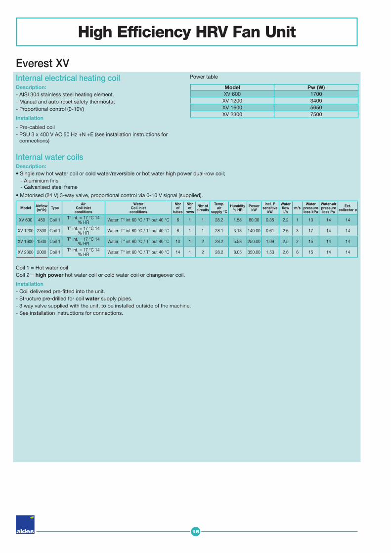
Everest XV Internal electrical heating coil Description:- AISI 304 stainless steel heating element.- Manual and auto-reset safety thermostat- Proportional control (0-10V)
Installation
- Pre-cabled coil- PSU 3 x 400 V AC 50 Hz +N +E (see installation instructions for
connections)
Coil 1 = Hot water coilCoil 2 = high power hot water coil or cold water coil or changeover coil.
Installation- Coil delivered pre-fi tted into the unit. - Structure pre-drilled for coil water supply pipes. - 3 way valve supplied with the unit, to be installed outside of the machine.- See installation instructions for connections.
Power table
Internal water coils Description:• Single row hot water coil or cold water/reversible or hot water high power dual-row coil; - Aluminium fi ns - Galvanised steel frame
• Motorised (24 V) 3-way valve, proportional control via 0-10 V signal (supplied).
Model Pw (W)XV 600 1700XV 1200 3400XV 1600 5650XV 2300 7500
Model Airflow (m3/h) Type
AirCoil inlet
conditions
WaterCoil inlet
conditions
Nbrof
tubes
Nbrof
rows
Nbr of circuits
Temp. air
supply °C
Humidity% HR
Power kW
incl. Psensitive
kW
Water flow l/h
m/sWater
pressure loss kPa
Water-air pressure loss Pa
Ext. collector ø
XV 600 450 Coil 1 T° int. = 17 °C 14 % HR Water: T° int 60 °C / T° out 40 °C 6 1 1 28.2 1.58 80.00 0.35 2.2 1 13 14 14
XV 1200 2300 Coil 1 T° int. = 17 °C 14 % HR Water: T° int 60 °C / T° out 40 °C 6 1 1 28.1 3.13 140.00 0.61 2.6 3 17 14 14
XV 1600 1500 Coil 1 T° int. = 17 °C 14 % HR Water: T° int 60 °C / T° out 40 °C 10 1 2 28.2 5.58 250.00 1.09 2.5 2 15 14 14
XV 2300 2000 Coil 1 T° int. = 17 °C 14 % HR Water: T° int 60 °C / T° out 40 °C 14 1 2 28.2 8.05 350.00 1.53 2.6 6 15 14 14
17
High Efficiency HRV Fan Unit
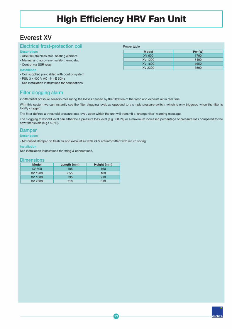
Everest XV Electrical frost-protection coil Description:- AISI 304 stainless steel heating element.- Manual and auto-reset safety thermostat- Control via SSR relay
Installation- Coil supplied pre-cabled with control system - PSU 3 x 400 V AC +N +E 50Hz- See installation instructions for connections
DamperDescription:
- Motorised damper on fresh air and exhaust air with 24 V actuator fi tted with return spring.
InstallationSee installation instructions for fi tting & connections.
Power table
Dimensions
Model Pw (W)XV 600 1700XV 1200 3400XV 1600 5650XV 2300 7500
Model Length (mm) Height (mm)XV 600 405 160XV 1200 655 160XV 1600 735 210XV 2300 710 310
Filter clogging alarm2 differential pressure sensors measuring the losses caused by the fi ltration of the fresh and exhaust air in real time.
With this system we can instantly see the fi lter clogging level, as opposed to a simple pressure switch, which is only triggered when the fi lter is totally clogged.
The fi tter defi nes a threshold pressure loss level, upon which the unit will transmit a 'change fi lter' warning message.
The clogging threshold level can either be a pressure loss level (e.g.: 60 Pa) or a maximum increased percentage of pressure loss compared to the new fi lter levels (e.g.: 50 %).

18
High Efficiency HRV Fan Unit
Everest XV
Principle
Aldes has developed the Everest Selector software to help you choose your high-effi ciency Everest HRV unit. In just a couple of minutes you can defi ne your technical and economic choices, and put together a complete technical dossier for your clients or to integrate into your specifi cations manuals.
1. Integrating all the components required for your project. • Your operational restrictions and the summer/winder temperature data• Your options: preheating, post-heating, post-cooling, fi lter effi ciency,
etc.• Additional information relating to your required confi guration: Active
silencers, dampers, etc.➜ Using powerful algorithms, the Selector Everest software can fi nd the
perfect unit for your needs in just a few seconds.
2. Obtain a complete technical dossier.• The performance stats of your unit (effi ciency, SFP, etc.) as well as a
general plan• CAD plans and wiring diagrams• The technical and commercial documentation for the product• Regulatory texts• Costing in just a few clicks
➜ Download, save and distribute your technical dossier.
Start your design work right now: The Everest Selector software can be downloaded free of charge, from www.aldes.fr, Professional section, under the heading "Software" (Logiciels).
EVEREST SELECTOR
The advantages of the Everest Selector software- Intuitive, 4-step interface with interactive fl owcharts- Rapid data entry and loading - Visualisation of all units for a project- Multi-project management- Transmission of technical dossiers by e-mail

19
1
3
9
2
5
8
6
7
4
High Efficiency HRV Fan Unit
Everest XV Schéma général
1 Casing
4 Bypass
3 Heat Exchanger
2 Fan
5 Aldes Smart Control® System
8 Electrical heating coil
6 Filters
7 Coil connections
9 Condensate discharge
High Efficiency HRV Fan UnitHigh Effi ciency HRV Fan Unit
EVEREST XVField of application• Heat recovery ventilation for energy-effi cient non-
residential buildings of all types: offi ces, schools, hotels, residences for the dependent elderly, etc.
• Filtration and preheating / cooling of incoming air.
Installation• Utility rooms / fl at roofs.
• Indoors / outdoors
• Rectangular (or optional circular) connections.
• Choice of side for equipment fi ttings (left or right).
• Customised plan supplied with the machine and its accessories.
Advantages• High-efficiency (>90%) HRV units.• Exclusive Aldes Smart Control® system.• Optimal air quality and thermal comfort.• Easy to install and activate.• Selector software specific to Everest for product
selection and performance calculations.
www.aldes.com
Ever
est_
XV_T
ech_
Corp
_Gb_
1 -
08/2
015
- RC
S Ly
on 9
56 5
06 8
28 -
Ald
es -
Ald
es re
serv
es th
e rig
ht to
mod
ify it
s pr
oduc
ts a
t any
tim
e to
intr
oduc
e ne
w te
chno
logi
es.
■ ALDES AÉRAULIQUE - Head Office: Tel: +33 4 78 77 15 15 - Fax: +33 4 78 76 15 97 ■ ALDES INTERNATIONAL - Tel: +33 4 78 77 15 34 - Fax: +33 4 78 77 15 56