everything you want to know about emergency … · emergency, legally required ... understanding of...
TRANSCRIPT

EVERYTHING YOU WANT TO KNOW ABOUTEMERGENCY GENERATORS
Power Quality and Generators – Sizing and Code IssuesKeith Lane, P.E., RCDD/NTS Specialist, LC, LEED APVice President - EngineeringSASCO, Seattle
The need for continuous electrical power and life-safety systems has increased formany installations. Critical installations that require reliable power quality typicallyinclude a standby generator for essential loads. In addition, these generators canprovide power to code required life safety or legally required standby loads.
There are important sizing and code issues involved in effectively designing andspecifying a standby generator. Generators are typically specified with a kW ratingand an associated power factor. Together, these values indicate the maximum kW(real power) and kVA (apparent power) that the generator will produce.
Mathematically, power factor is the ratio between kW and kVA (PF = kW / kVA). It isa measure of how efficiently the current is being converted into useful work. At lowpower factors, more current will be required to provide the same amount of power.
An engineer must consider both the engine and generator individually and as asystem. Engines produce the real power (kW) or horsepower and control frequency.Generators change the mechanical energy into electrical energy (kVA) and mustsatisfy magnetization current (kVAR) within an electrical system.
Often times a more critical parameter in sizing a generator is the maximum skVA(starting kVA) and maximum skW (starting kW) allowed. The skVA is dependent onthe maximum allowable voltage drop during starting and will be lower for moresensitive critical loads, or where lower maximum voltage drops are required by code.
It is common for a systems stating kVA and maximum allowable voltage drop todrive the size of the generator. Motors can draw six times the full load amps duringstart up. High efficient motors can draw ten times the full load current or more. Thismeans that the starting of motors can dramatically effect the skVA required and mayexceed the maximum skVA of a generator that would otherwise be large enough toserve the steady state load. This could require an oversized generator based solelyon the motor starting requirements.
Staggering the starting of large motors and/or providing soft starters or variablefrequency drives (VFD) can mitigate the voltage drop problem by reducing the inrushcurrent and kVA. Staggering the starting of large motors can reduce the peakstarting kVA to within limits of a smaller generator. When providing steps betweenloads, the designer must be aware of all codes and maximum allowable starting timedelays for life safety and legally required standby loads.
Soft starters or VFD's can reduce the starting inrush current and kVA to half of thatof an across the line starter. On the down side, these devices also utilize SCR's(silicon controlled rectifiers) to chop up the AC waveform and will provide a non-linear waveform. This non-linear waveform (harmonics) will cause voltage distortionacross the reactor of the generator and can cause unacceptable transientperformance. This will adversely affect the performance of the entire system. Voltagedrop and voltage distortion will be much higher when a facility is under generatorpower than when on utility power. Typical generators will have 15-20% internalreactive impedance, whereas utility transformers will typically have between 2-5%internal reactive impedance.

Waveform notching caused by this voltage distortion can be detrimental to solidstate timing devices that rely on zero crossing switches. To compensate for thevoltage distortion from non-linear loads, a larger generator with reduced impedancecan reduce the effects caused by the non-linear load.
The design engineer must be aware of the intended use of the on site generator.Depending on the load factor, typical application, typical peak loading and typicalhours per year, the generator will require either a standby rating, a prime rating or acontinuous rating. In addition, code issues will drive the required rating of an on-sitegenerator. Operating a generator beyond it rating will result in a shorter life andmore expensive operating costs. It is important to reference a generators intendeduse to manufacturers warrantee restrictions in regard to run time per year.
Regenerative loads such as conveyors, cranes and elevators can rely on the powersource to absorb power during breaking. These types of loads in the system canaffect the size and type of generator. In addition planning loading and stepping toensure that other loads are connected that can absorb the regenerative power canhelp solve this potential problem.
It is possible to have a single generator feed life safety and non-life safety loads. TheNational Electric Code (NEC 700.5 B) will allow an alternate power source to supplyemergency, legally required standby and optional loads, where automatic selectiveload pickup and load shedding as needed is implemented to ensure adequate powerto life safety, legally required standby and optional loads, in that order. This can beachieved by providing a separate automatic transfer switch (ATS) for each of thethree branches of loads (life safety, legally required standby, optional).
As a side benefit, the three branches of automatic transfer switches can provideconvenient load stepping during generator startup. This will typically reduce therequired size of the generator. The transfer switches must be timed to reduce themaximum skVA and meet all NEC transfer time parameters for life safety and legallyrequired standby loads.
Standby power systems can be complex. Effectively designing electrical systems withmultiple automatic transfer switches and multiple types of loads requires a thoroughunderstanding of generator sizing criteria and of the various applicable codes.
Conservatively over sizing a generator from not clearly understanding sizingrequirements will not only add undo expense to a project, but can also bedetrimental to the reliability of the system. Most manufacturers recommend thatdiesel engines should not be run at less than 10% of rated load for extended periodsand in general recommend that loads do not drop below 30% of the rating of thegenerator. Check manufacturer recommendations for specific installations.
The engineer must also be aware of the minimum amount of on site fuel supplyrequired for an internal combustion prime mover serving as a power source foremergency systems. A minimum amount of on site fuel storage is identified insection 700 of the National Electric Code. For large generator, the minimum amountof on site fuel supply can exceed the limits set forth by building and/or fire codes andcan lead to additional system requirements including; separate fuel supply systems,Class H, Division 3 occupancies or UL 2085 tanks with integral secondarycontainment.
Many jurisdictions are now requiring generators to be UL 2200 (Stationary EngineGenerator Assembly) listed and labeled. This standard represents a national productsafety requirement for generators. These requirements cover stationary and fixedgenerators rated 600 volts or less and are intended for installation and use inordinary locations in accordance with the National Electric Code. This requirementhas only been enforced in the past few years. Owners and engineers consideringutilizing used generators should ensure UL 2200 compliance and coordinate withlocal code officials.

Generator system design and sizing can be complex. To effectively design and sizegenerator systems, an engineer needs to understand the effects of differentcomponents in the electrical system and be able to navigate through the variouselectrical, building and NFPA codes.
Future installments in this series will provide more in-depth analysis of other criticalengineering and code issues involved in effective design and specification ofgenerator systems.
Power Quality and Generators – Complying with theCodes and Controlling NoiseLooks at standby, prime, and continuous ratings, plus noise level concerns.
References to standby, prime and continuous ratings were identified in my firstcolumn in this series on generators. This subject is critical but is sometimesoverlooked. Therefore, it deserves some additional clarification.
Once an engineer has identified the anticipated environment and load profile in whichthe generator is going to be located, additional sizing constraints must beconsidered. There are typically three ratings that can be applied to generators:standby rating, prime rating and continuous rating.
Standby-rated generators for life-safety and legally required standby loads, as wellas for some optional loads, are intended to be used in the event of an unusual utilitypower outage. The standby rating typically means rated to be run 100 hours peryear, have a load factor of 60% or less and have a typical peak demand of 80% ofstandby-rated kW with 100% available for the duration of an emergency outage.
Prime-rated generators are typically standby-rated generator de-rated to 90% oftheir standby rating. The prime-rated generator is typically rated to have no limit tothe number of run hours per year. In addition, the load factor is rated at 60% to70%. Normally, the peak demand is rated at 100% of prime-rated kW for occasionaluse, but for less than 10% of operating hours. Typical applications are for industrial,peak shaving or cogeneration operations.
Continuous-rated generators are usually standby-rated generators de-rated to 80%of their standby rating. The continuous-rated generator is typically rated to have nolimit to the number of run hours per year. In addition, the load factor is rated at70% to 100%, and typically, peak demand is rated at 100% of continuous-rated kWfor 100% of operated hours. Like prime-rated, these, too, are generally for industrialfacilities, peak shaving or cogen.
Load factor is described as the sum of the loads a generator set experiences, while itis running under load, divided by the number of hours it operates under those loads.
Maintenance and warranty issues may become a problem if these generator ratingsare exceeded. The engineer must reference specific generator ratings and warrantyissues. The types and specifications noted above are for reference only.
Generator system design and sizing can be complex. To effectively design and sizegenerator systems, an engineer needs to understand the effects of differentcomponents in the electrical system and be able to navigate through the variouselectrical, building and NFPA codes.
The International Building Code represents additional challenges to the designengineer. Because many jurisdictions have adopted the IBC code, with provisions

that will affect the sizing, location and fuel supplies of standby generators, its worthtaking a look at some of the issues here.
For example, IBC 403.10.1 specifically indicates that a generator set inside a buildingshall be enclosed with two-hour fire resistant rated fire barrier assemblies. This codesection must be discussed with the design team architect to ensure proper codecompliance.
IBC Table 414.2.2 indicates the percentage of maximum allowable quantity percontrol area for diesel fuel storage. Any level above or below grade has allowedmaximums lower than 100% of those quantities stated in IBC Table 307.7 (1). TheIBC indicates that, in a non-sprinkled building, a maximum of 120 gallons of dieselfuel is allowed. In a sprinkled building, the total is doubled to 240 gallons of dieselfuel. Based on IBC tables noted above, for a storage area two floors below grade, anon-sprinkled building would have a maximum allowable fuel storage of only 60gallons. This represents a 50% reduction just based on the location of the storagetank. In addition, fuel storage is not allowed in areas lower than two stories belowgrade.
IBC 3003.1.4, Venting, indicates that where standby power is connected to theelevators, the machine room ventilation or air conditioning shall be connected to thestandby power source.
IBC 1007.2.1 addresses buildings with four or more stories and indicates that, inbuildings where a required accessible floor is four or more stories above or below thelevel of exit discharge, at least one required accessible means should be an elevator.The IBC then goes on to dictate that that standby power must be provided as perchapter 27 and 30. Chapter 27 dictates the use of stationary generators. Thisprovision could certainly increase the number of generators required on futureprojects.
I recommend coordinating with your authority having jurisdiction for their finalinterpretation of these codes prior to completing design documents.
Also, many state and local AHJs enforce noise ordinances. For instance, theWashington State Administrative Code identifies three classification: Class A forresidential, Class B for commercial and Class C for industrial areas.
When the noise source is in a Class B commercial zone and the receiving propertyline is in a Class B zone, the maximum noise level shall not exceed 60 db. Other localjurisdictions enforce even stricter noise ordinances that allow lower dB levels at theopposing property line. Critical grade mufflers, silencers and sound suppressionenclosures may be required to meet these ordinances. Additionally, locating thegenerator as far away from the adjacent property line can reduce the noise levels.
Sound levels and noise levels, as specified in jurisdictional noise ordinances and inacoustical measurements, are expressed in decibels (dB). These sound levels areweighted to be consistent with the normal sensitivity of the human ear. This isreferred to as an A-weighted sound level, abbreviated (dBA). To give you somereference as to what these dBA levels represent as far as real life noise, 0 dBA is thethreshold of hearing, a whisper is about 30 dBA, normal conversation is about 50dBA, a rock concert is about 120 dBA and a nearby jet is about 150 dBA.
As sound travels away from its source and spreads over a large area, it decreases inloudness. Sound decreases by about 6 dB for every doubling of distance from thenoise source. A doubling of noise power would represent a 3 decibel (dB) increase. A6 dB increase would occur if the power goes up by a factor of four times. The decibelchange would be 10 dB for an increase of 10 times the noise power. Noise ismeasured using a logarithmic scale. It is apparent that the logarithmic scalecompacts the dBA measurement values and makes them appear to have less of aneffect than they actually do on the noise level.

If an acoustical analysis indicates that there is only a 3 dB increase in noise, itmeans that the noise power has been doubled. In a loud environment, during theday in an industrial area, you may not be able to distinguish a 3 dB increase. If thesurrounding area is quit, say for instance at night in a residential area when theambient noise is at a much lower level, one will probably notice this change in noisepower.
An exterior mounted generator with a critical grade muffler and a sound attenuatedenclosure. Radiator and combustion air is intake is taken from the lower right sectionof the enclosure. Radiator output is expelled on the upper left section. Total noiseoutput is relegated to a virtual hum.
Occupational Safety and Health Administration (OSHA) has proposed permissiblenoise exposure times. Some of these are listed below:
85 dB and higher - prolonged exposure will result in hearing loss 90 dBA - no more than 8 hours per day 95 dBA - no more than 4 hours per day 100 dBA - no more than 2 hours per day 105 dBA - no more than 1 hour per day
Noise control can be achieved by eliminating mechanical noise and exhaust noise.Isolating the engine from the structure with vibration isolators can controlmechanical noise emanating from the structure housing the generator. Mechanicalnoise emanating in the air can be controlled with the use of sound enclosures,baffles, absorption materials or a combination of all the methods. Below is a list ofthe methods and the approximate sound level dB(A) reduction.
Vibration isolators 2 dB(A) Baffles 5 dB(A) Absorption materials 5 dB(A) Rigid sealed enclosure 15-20 dB(A) Enclosure and isolators 25-30 dB(A) Enclosure, absorption and isolators 35-40 dB(A) Double walled enclosure, absorption and isolators 60-80 dB(A)
The most common way to reduce exhaust noise is with a silencer. This measure canreduce exhaust noise by 15 dB(A) when measured at 3 meters or 10 ft from thesource.
Generator db(A) levels are typically given for distances of 7 meters or 23 ft from thegenerator. For instance, an exterior mounted 900 kW generator in a rigid sealedenclosure can have noise levels above 80 dB(A) at 23 ft. The same generator in anoise rated enclosure can lower those levels to 65 dBA at 7 meters or 23 feet.Depending on the size of the generator, the proximity to the adjoining property lineand the extent of the noise regulations, it may be appropriate to hire a qualifiedacoustical consultant to calculate and simulate post construction noise levels toensure compliance with regulations.

Power Quality and Generators – Fuel Configurations forStandby Gensets
This column covers various alternative fuel configurations that can be used forstandby generators. We'll also review the National Electrical Code (NEC)requirements for on-site fuel supplies and concerns over liquid petroleum storageand gas piping.
In my experience, when a typical commercial building or critical infrastructure uses astandby generator, it is most often diesel-driven. As long as a diesel engine is keptwarm when not in operation, starting reliability is very good.
There are other sources of fuel that can be utilized to power a standby generator.Some of these sources include:
Natural gas only Natural gas and propane Lean burn Natural gas and diesel combination
In all cases, if the generator will feed life-safety loads, it must comply with NECrequirements for an on-site fuel supply. NEC Section 700.12(B)2, “InternalCombustion as Prime Mover,” indicates that where an internal combustion engine isused as the prime mover for an emergency generator to feed life-safety loads, thesystem shall be provided with an on-premises fuel supply sufficient for not less thantwo hours of the system at full-load amps. If a natural gas generator is designed tofeed life-safety loads, it will also require two hours of on-premises fuel source. Thisrequirement can be met with either a propane or diesel supply.
Natural gas alone will not comply with the NEC. Natural gas is piped by the servingutility from their distribution system to the generator. A regulator is typicallyrequired to reduce the gas pressure at the generator to safe working levels. Asolenoid valve controls the flow of gas to the regulator and generator carburetor.There is no actual on-premises storage of fuel when the natural gas is supplied bythe utility.
The downside of only using natural gas is obvious: In the event of a disaster, such asan earthquake, at a time when you need the standby generator the most, the naturalgas fuel line could be ruptured, rendering the generator useless. A standby source ofpropane or diesel would be necessary.
Environmental concerns, clean air legislation and operating costs of diesel generatorshave increased the interest in bi-fuel products. A dual-fuel generator capable ofburning diesel and natural gas can be advantageous, because its exhaust is less toxicthen diesel.
However, the difficulty with this strategy is in maintaining the best possible balanceof diesel and natural gas throughout the power range of the load. This regulationprocess must be maintained in an environment of potentially changing ambienttemperatures. With newer technology, advanced microprocessor controls haveimproved this process.

At left, one sees the natural gas supply line on the bi-fuel generator. The graph onthe right indicates the percentage of load and the percent usage of natural gas anddiesel fuel. (Courtesy: Generac)
But keep in mind that at no time can the diesel and natural gas combinationgenerator operate purely on natural gas. Some of the diesel fuel is required forcompression ignition. Natural gas has a much higher ignition temperature thandiesel. During the startup, the system runs on 100% diesel fuel.
After startup, the system brings in more natural gas with the air intake. At the sametime, the amount of diesel fuel is reduced. This whole process is monitored with theactual load requirements and ambient temperature to ensure the correct mix offuels. The optimal bi-fuel ratio under normal operation is a 10% diesel and 90%natural gas mix.
Under these conditions, a smaller amount of diesel fuel would be required to meetthe two hours of standby fuel requirements. On the other hand, the same amount ofdiesel fuel could operate a building significantly longer than two hours. One studydescribes an example of a 300-kW generator loaded 80% to 240 kW with a 183-gal.diesel tank having a diesel only runtime of 8.9 hours (see Generac website). The bi-fuel run time was extended to 76.2 hours or 3.2 days. This extended run time is aclear advantage in an extended power outage. In addition, the bi-fuel technologyreduces the exhaust emissions.
Another technology utilizes what is referred to as “lean burn.” This technology allowsthe engine to run on a wide range of gasses, including natural gas, field gas or bio-gas. Any gas with a methane number of 50 can be used. De-rating of the generatoroutput may be required if utilizing a gas with a methane number of below 70. Thissystem can be utilized with a propane tank at the generator as the standby sourceand comply with NEC requirements. This system also reduces the emissions of NOxand other pollutants.
Courtesy: Cummins

Some gasses can contain unacceptable levels of higher hydrocarbons and hydrogensulfide. Use of gas with a low methane number can cause operating problems andlead to increased maintenance costs and downtime.
When utilizing a natural gas and propane unit, either of the gasses can be utilized.These gasses are not mixed as they are in the diesel and natural gas combinationunits.
In a natural gas and LP vapor dual-fuel system, the natural gas supply pressure ismonitored. When the pressure of the natural gas supply drops below a presetthreshold, the natural gas solenoid valve is closed and the LP vapor solenoid valve isopened. The generator is then served by the LP vapor.
In a natural gas and LP liquid dual-fuel system, the natural gas supply pressure ismonitored. When the pressure of the natural gas supply drops below a presetthreshold, the natural gas solenoid valve is closed. The LP liquid flows into thevaporizer regulator, which converts the LP liquid into a LP vapor. The generator isthen served by the LP vapor.
Vapor propane systems draw the fuel from the top of the tank. The liquid in thebottom of the tank must absorb enough heat energy for the vaporization process tooccur. Very cold climates can cause poor fuel flow. A liquid withdrawal systemeliminates this process.
A liquid propane tank should not be installed inside a building. The LP tank should beinstalled outside away from electrical connection sparks or open flames.
Fuel consumption on propane at full load is about 40 gal. per hour for a 331-kW unit.This would equate to about 80 gal. for NEC required two hours of fuel, 320 gal. for 8hours and 1000 gal. for 25 hours.
The engineer must coordinate with the local electrical plan reviewer and fire marshalto ensure that all codes referencing on-site fuel storage and gas piping are followedprior to construction.
Finally, no review of alternative fuels would be complete without a discussion of fuelcells. A fuel cell can provide direct current voltage that can be used to powerdevices. Current technology will allow a proton exchange membrane fuel cell the sizeof a piece of luggage to power a car. Fuel cells for homes and commercial use arejust starting to become available. This technology can utilize methanol, natural gasand propane as the fuel source. Issues such as hydrogen infrastructure and life ofthe fuel cell need to be addressed and improved before this technology becomesmore widespread.

Power Quality and Generators, Basic Calculations forSizing Generators and the Impacts of Certain Loads
Once the starting kVA (sKVA), starting kW (sKW) and the alternator kWrequirements are calculated by hand for generator sizing, these values are fed intosizing software to determine a particular manufacturer's recommended generatorsizes. Although many generator simulation software programs are available, knowingthe basics of generator sizing calculations will help the system designer understandthe impact that certain loads and starting methods have on the ultimate size of thestandby generator.
It is common for a system's sKVA—or its sKW and maximum allowable transientvoltage drop—to determine the size of the generator. Motors can draw six times thefull-load amps during startup. The motor's NEMA code letter, which identifies thestarting kVA/hp, is a representation of the starting inrush current. The examplebelow uses a NEMA “F” motor. Based on this letter code, the motor will drawapproximately 5.3 kVA/hp. Using the following calculation for a 150 hp motor with91% efficiency and 0.91 power factor, the motor will draw approximately 5.9 timesthe full-load current during motor starting:
Calculation #1150 hp x 5.3 kVA/hp = 795 kVA = 956.6 amps @ 480 volt/3 phase (amps duringstartup)
(150 hp x 0.746 kW/hp) / 0.91 (efficiency) = 123.0 kW (running kW)
123.0 kW / 0.91 (power factor) = 135.1 kVA = 162.5 amps (represent full-loadamps)
956.6 amps (during startup) / 162.5 A (full-load amps) = 5.9 (times full-loadcurrent)
High-efficiency motors can draw ten or more times the full-load current. As acomparison, for a motor with a NEMA “K” rating (8.5 kVA/hp), the inrush currentwould have been significantly higher (9.4 times full-load current). The followingcalculation uses a 150-hp motor with 91% efficiency and 0.91 power factor:
Calculation #2150 hp x 8.5 kVA/hp = 1,275 kVA = 1,534 amps @ 480 volt/3 phase (amps duringstartup)
(150 hp x 0.746 kW/hp) / 0.91 (Efficiency) = 123.0 kW (running kW)
123.0 kW / 0.91 (power factor) = 135.1 kVA = 162.5 amps (represent full-loadamps)
1,534 amps (amps during starting) / 162.5 amps (full-load amps) = 9.4 (times full-load current)
This illustrates that the starting of motors can dramatically affect the inrush currentand associated sKVA and the sKW required and may exceed the maximum sKVA orthe sKW of a generator set that would otherwise be large enough to serve the steadystate load. This could require an oversized generator set based solely on the motorstarting requirements of the electrical system.
To clarify this issue, I will use an example with the same load profile but with twodifferent methods of motor starting. These simple examples will include lighting and

miscellaneous loads as well as motor starting with an across the line starter in oneexample and a solid-state starter in another example.
Example #1: Motor with an across the line starter
Motor Load: 150-hp motor, NEMA “F” with a 0.28 startingpower factor
Running power factor of 0.91 and an efficiency of 0.91.
NEMA Code Letter “F” = 5.3 kVA/hp
sKVA = 150 hp x 5.3 kVA/hp = 795 kVA
sKW = 795 kVA x 0.28 (starting power factor) = 222.6 kW
Running kVA = 123.0 kW / 0.91 (power factor) = 135.1 kVA
Running kW = (150 hp x 0.746 kW/hp) / 0.91 (Efficiency) = 123.0 kW
Lighting Load: 75 kVA at 0.9 power factor
sKVA = 75 kVA
sKW = 75 kVA x 0.9 power factor = 67.5 kW
Running kVA = 75 kVA
Running kW = 75 kVA x 0.9 power factor = 67.5 kW
Miscellaneous Load: 50 kVA at 0.9 power factor
sKVA = 50 kVA
sKW = 50 kVA x 0.9 power factor = 45 kW
Running kVA = 50 kVA
Running kW = 50 kVA x 0.9 power factor = 45 kW
System Totals:
sKVA = 795 + 75 + 50 = 920 kVA
sKW = 222.6 + 67.5 + 45 = 335.1 kW
Running kVA = 135.1 + 75 + 50 = 260.1 kW
Running kW = 123 + 67.5 + 45 = 235.5 kW
Alternator kW = 123 + 67.5 + 45 = 235.5 kW
Using one manufacturer's sizing software, the recommended generator set size is350 kW. This is based on about a 20% transient voltage dip followed by a sustainedrecovery of 90% of rated voltage during starting. The generator would run at about67% of capacity (Running kW = 236, Generator Capacity = 350 kW, 236 / 350 =67.4%).
Large motors that are started with across-the-line starters fed by generators to allowfor very low transient voltage drop during starting can require a greatly oversizedgenerator set. In these cases the running capacity of the generator can besignificantly lower than the rating of the generator set. It is critical to ensure that therunning load represents at least 30% of the rated size of the generator set or wetstacking or carboning can occur. See Part 7 for definitions and a discussion of theseterms.
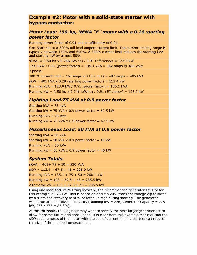
Example #2: Motor with a solid-state starter withbypass contactor:
Motor Load: 150-hp, NEMA “F” motor with a 0.28 startingpower factor
Running power factor of 0.91 and an efficiency of 0.91.
Soft Start set at a 300% full load ampere current limit. The current limiting range istypically between 150% and 600%. A 300% current limit reduces the starting kVAand starting kW by almost 50%.
sKVA, = (150 hp x 0.746 kW/hp) / 0.91 (efficiency) = 123.0 kW
123.0 kW / 0.91 (power factor) = 135.1 kVA = 162 amps @ 480-volt/
3 phase.
300 % current limit = 162 amps x 3 (3 x FLA) = 487 amps = 405 kVA
sKW = 405 kVA x 0.28 (starting power factor) = 113.4 kW
Running kVA = 123.0 kW / 0.91 (power factor) = 135.1 kVA
Running kW = (150 hp x 0.746 kW/hp) / 0.91 (Efficiency) = 123.0 kW
Lighting Load:75 kVA at 0.9 power factor
Starting kVA = 75 kVA
Starting kW = 75 kVA x 0.9 power factor = 67.5 kW
Running kVA = 75 kVA
Running kW = 75 kVA x 0.9 power factor = 67.5 kW
Miscellaneous Load: 50 kVA at 0.9 power factor
Starting kVA = 50 kVA
Starting kW = 50 kVA x 0.9 power factor = 45 kW
Running kVA = 50 kVA
Running kW = 50 kVA x 0.9 power factor = 45 kW
System Totals:
sKVA = 405+ 75 + 50 = 530 kVA
sKW = 113.4 + 67.5 + 45 = 225.9 kW
Running kVA = 135.1 + 75 + 50 = 260.1 kW
Running kW = 123 + 67.5 + 45 = 235.5 kW
Alternator kW = 123 + 67.5 + 45 = 235.5 kW
Using one manufacturer's sizing software, the recommended generator set size forthis example is 275 kW. This is based on about a 20% transient voltage dip followedby a sustained recovery of 90% of rated voltage during starting. The generatorwould run at about 86% of capacity (Running kW = 236, Generator Capacity = 275kW, 236 / 275 = 85.8%).
At this threshold, the engineer may want to specify the next larger generator set toallow for some future additional loads. It is clear from this example that reducing thesKW requirements of the motor with the use of current limiting starters can reducethe size of the required generator set.

The solid-state starter will cause voltage distortion across the alternator of thegenerator. This distortion is cause by the nonlinear way the silicon-controlledrectifiers (SCRs) in the solid-state starter draw current. The generators alternatormay have to be oversized to compensate for this voltage distortion. This issue can beavoided, as in the example above, by specifying a bypass contactor with the soldstate starter. The bypass contactor closes after startup and the SCRs are onlyoperating during the starting of the motor. If the solid-state starter does not have abypass contactor, a rule of thumb is to add again the motor running kW to therunning kW of the system. This calculation will estimate the total alternator kW. Seecalculation below:
Alternator kW with a bypass contactor: 235 kW
Alternator kW without a bypass contactor: 235 kW + 123 kW = 358 kW
If the soft starter does not have a bypass contactor, the engineer must determine ifa larger alternator is required. In our example above, the same 275-kW generatorcan handle either case (with and without a bypass contactor), but a larger alternatoris required to handle the additional alternator kW if no bypass contactor is specified.
In our example above, in the across-the-line starter situation, the sKW drove therequirement for the larger generator set. Below is a breakdown of some of thecritical parameters for the different starting methods as well as the two generator setsizes noted above. Three total generator set configurations have been noted below,one for 350 kW and two for 275 kW. The 275-kW generator set has been split into asmaller and a larger alternator. The parameters (sKVA, sKW and alternator kW)noted under the three generator set configurations are the maximum the generatorset can provide. The parameters noted under the form of motor starting are therequirements for the different system examples noted above with their associatedform of motor starting configuration.
Chart 1
sKVA sKW Alternator kW
275 kW Genset w/ Small Alternator 1028 291 300
275 kW Genset w/ Larger Alternator 1372 293 380
350 kW Genset 1896 518 515
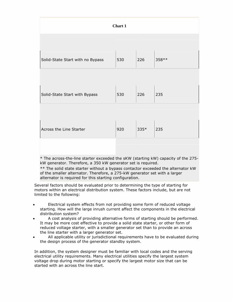
Chart 1
Solid-State Start with no Bypass 530 226 358**
Solid-State Start with Bypass 530 226 235
Across the Line Starter 920 335* 235
* The across-the-line starter exceeded the sKW (starting kW) capacity of the 275-kW generator. Therefore, a 350 kW generator set is required.
** The solid state starter without a bypass contactor exceeded the alternator kWof the smaller alternator. Therefore, a 275-kW generator set with a largeralternator is required for this starting configuration.
Several factors should be evaluated prior to determining the type of starting formotors within an electrical distribution system. These factors include, but are notlimited to the following:
Electrical system effects from not providing some form of reduced voltagestarting. How will the large inrush current affect the components in the electricaldistribution system?
A cost analysis of providing alternative forms of starting should be performed.It may be more cost effective to provide a solid state starter, or other form ofreduced voltage starter, with a smaller generator set than to provide an acrossthe line starter with a larger generator set.
All applicable utility or jurisdictional requirements have to be evaluated duringthe design process of the generator standby system.
In addition, the system designer must be familiar with local codes and the servingelectrical utility requirements. Many electrical utilities specify the largest systemvoltage drop during motor starting or specify the largest motor size that can bestarted with an across the line start.

For example, one of our local electrical utilities, Seattle City Light, indicates that“reduced starting current shall be required on all motors exceeding 15 hpnameplates rating, unless otherwise agreed to by the utility.” Another serving utilityin our area, Puget Sound Energy, indicates, “If the voltage dip exceeds 2%, thetransformer size must be increased to reduce the dip to 2%. The customer isresponsible for the difference in cost of the larger transformer.” When only themaximum allowable voltage dip is indicated as a requirement, the largest allowedmotor without some form of reduced voltage starting will be based on the size andimpedance of the serving utility transformer.
Another form of reduced-voltage starting is the variable-frequency drive. VFDs canreduce both sKVA and sKW. They draw load in a nonlinear fashion, similar to thesolid-state starter, and will continue to draw loads in a nonlinear manner, as thefrequency of the motor can be altered by control devices through the entireoperation of the motor. The size of a generator set feeding a system with a VFD mayhave to be increased or may have to be fitted with an oversized alternator similar tothat of a system feeding a soft start without a bypass contactor. The use of 12-pulseIGBTs (Insulated Gate Bipolar Transistor), (PWM) pulse width modulated drives andharmonic filtering can make the VFD more generator-friendly.
In addition, stepping the sequence of the loads within the requirements of theNational Electric Code, Section 700 can greatly reduce the sizing of the generatorset. Since larger generators are often required because of the peak kW or kVA on thesystem, stepping the loads long enough for the inrush of motors not to besimultaneous can reduce the ultimate size of the generator set required to feed thecritical loads.
Power Quality and Generators – Design Criteria forGrounding
Standby generator system grounding must be understood to ensure proper operationof the critical electrical systems. It is not my intent to cover all of the issues involvedin proper grounding of emergency standby systems, but to clarify some of the mainissues that tend to come up in most projects.
A standby generator system uses either a three- or four-pole automatic transferswitch (ATS) to transition from utility electrical power to standby electrical power inthe event of a loss of normal electrical service, as shown in Diagrams 1 and 2 below.
In a typical three-phase electrical distribution system, the engineer or systemdesigner has the choice between a three-pole or four-pole ATS. There are certaincircumstances where a four-pole ATS will be required, typically where the electricaldistribution system has two or more levels of ground fault sensing and two or moreATS. Per the National Electric Code, Article 230-95, ground fault protection isrequired on solidly grounded equipment 277/480-volt rated at 1,000 amps or more.Where a single level of ground fault is required by NEC, Section 517, hospitals willrequire a second level of ground fault protection to ensure service continuity during aground fault on a branch feeder.
Although not required by code, other critical facilities may opt for multiple levels ofground fault protection to minimize the effect of a short to ground. In these cases ofmultiple levels of ground fault and of multiple automatic transfer switches, a four-pole ATS is required. If the neutral is not switched, neutral current due tounbalanced loading or non-linear loads can split in the parallel paths and causenuisance tripping of the ground fault sensor. A four-pole ATS switches the neutral; athree-pole does not.
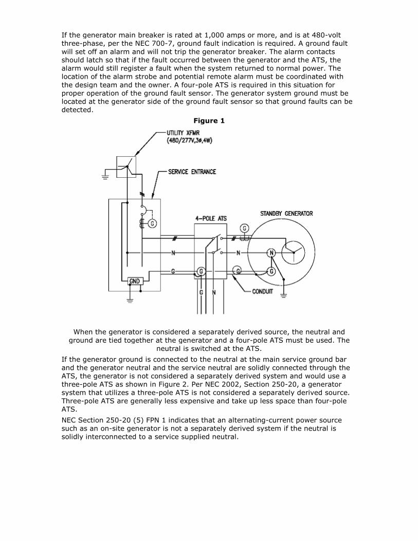
If the generator main breaker is rated at 1,000 amps or more, and is at 480-voltthree-phase, per the NEC 700-7, ground fault indication is required. A ground faultwill set off an alarm and will not trip the generator breaker. The alarm contactsshould latch so that if the fault occurred between the generator and the ATS, thealarm would still register a fault when the system returned to normal power. Thelocation of the alarm strobe and potential remote alarm must be coordinated withthe design team and the owner. A four-pole ATS is required in this situation forproper operation of the ground fault sensor. The generator system ground must belocated at the generator side of the ground fault sensor so that ground faults can bedetected.
Figure 1
When the generator is considered a separately derived source, the neutral andground are tied together at the generator and a four-pole ATS must be used. The
neutral is switched at the ATS.
If the generator ground is connected to the neutral at the main service ground barand the generator neutral and the service neutral are solidly connected through theATS, the generator is not considered a separately derived system and would use athree-pole ATS as shown in Figure 2. Per NEC 2002, Section 250-20, a generatorsystem that utilizes a three-pole ATS is not considered a separately derived source.Three-pole ATS are generally less expensive and take up less space than four-poleATS.
NEC Section 250-20 (5) FPN 1 indicates that an alternating-current power sourcesuch as an on-site generator is not a separately derived system if the neutral issolidly interconnected to a service supplied neutral.

Figure 2
When the generator is not considered a separately derived source, the neutral andground are not tied together at the generator and a three-pole ATS must be utilized.
The neutral is solidly connected at the ATS to allow the generator neutral to beconnected to the main service ground at all times (when the load is being served
from either the main service through the serving electrical utility or from the standbygenerator).
Because a generator that feeds a three-pole ATS is not considered a separatelyderived source, only the frame of the generator is grounded at the generator and notthe neutral. On the other hand, a generator feeding a four-pole ATS is considered aseparately derived source and the neutral is grounded at the generator.
In addition, a four-pole ATS is better than a three-pole switch from a maintenanceperspective. With the latter, if the main service is taken offline for maintenance andthe standby generator is running to serve the critical and life safety loads, thestandby generator is still relying on the main service ground connection to theneutral for the return path of any ground fault. If maintenance personnel are notaware of this grounding configuration, and maintenance is performed on the mainservice ground when the service is offline and the standby generator is running, thestandby generator would no longer be properly grounding. This could be a serioussafety concern and could potentially allow fault currents to flow without tripping theover current protective device.
NEC 2002, Section 250.50, defines the requirements for the grounding electrodesystem for the main electrical service. This section indicates that, “If available on thepremises at each building or structure served, each item in 250.52 (A) (1) though(A) (6) shall be bonded together to form the grounding electrode system.”(A) (1)through (A) (6) are noted below and include the following:
1. Metal underground water pipe.2. Metal frame of a building or structure.3. Concrete encased electrode.

4. Ground ring.5. Rode and pipe electrode.6. Plate electrodes.
This section of the NEC further states, “Where none of these electrodes are available,one or more of the electrodes specified in 250.52 (A) (4) through (A) (7) shall beinstalled and used.” (A) (4) through (A) (7) are noted below and include thefollowing:
4. Ground ring.5. Rode and pipe electrode.6. Plate electrodes.7. Other local metal underground system or structures.
The NEC 250.52 (A1) also states, “ If the water pipe is the only source used it mustbe connected within 5' of entering the building.”
Most generator systems are solidly grounded (direct connection with no intentionalimpedance), but intentional impedance can be added to the grounding system toallow a phase-to-ground fault to occur without taking down the standby system.
A high resistance ground system allows a fault to ground to occur without requiringthe overcurrent protective device to trip. In these systems, the added resistanceusually will only allow about 10 amps of fault current to flow through the system.The amount of intentional resistance should be carefully evaluated, as the total faultcurrent should be at least equal to the charge current of the system.
NEC Section 250.36 states that high-impedance grounding systems in which aground impedance, unusually a resistor, limits the ground fault current to a lowvalue shall be permitted for three-phase AC systems of 480 volt to 1,000 volts,where the following conditions are met:
1. The conditions of maintenance and supervision ensure that only qualifiedpersons service the installation.
2. Continuity of power is required.3. Ground detectors are installed on the system.4. Lines to neutral loads are not served.
This section of the NEC also indicates that provisions indicated in section 250.36 (A)through (G) shall be met. These provisions are too extensive to be completelydetailed in this article, but in summary, they indicate:
The ground impedance shall be installed between the grounding electrodeconductor and the system neutral.
The neutral point of the transformer or generator to the connection point ofthe grounding impedance shall be fully insulated.
The system neutral conductor shall not be connected to ground exceptthrough the grounding impedance.
The conductor connecting the neutral of the transformer or generator to thegrounding impedance shall be permitted to be installed in a separate raceway.
The equipment bonding jumper shall be un spliced and run from the firstsystem disconnecting means to the grounding side of the grounding impedance.
The grounding electrode conductor shall be attached at any point from thegrounded side of the grounding impedance to the equipment groundingconnection at the service equipment of first disconnect.
The equipment bonding jumper shall be sized based on 250.36 (G)

Consult the National Electrical Code for more information on this subject.
Fault currents occurring in high impedance grounded systems should be investigatedimmediately. If left to continue, a phase-to-ground fault could potential grow into aphase-to-phase fault. High-impedance grounded systems will not reduce the currentfrom a phase-to-phase fault, the overcurrent protective device will trip and criticalloads can go down.
Another method of grounding for standby generators is with a low-resistancegrounding system, where resistance is calculated to allow for relay protection toselectively operate. These current values are often around 400 amps for newsystems, but can be as high as 2,000 amps for larger, older systems.
A solidly grounded system will allow for the highest ground faults but will provide themost control of over voltages. A solidly grounded system has the highest probabilityof escalating into a phase-to-phase or three-phase arcing fault, particularly for 480-volt and 600-volt systems. In addition, severe arc flash and burning can occur from aphase-to-ground fault in a solidly grounded system.
The engineer or system designer should be familiar with all of the common methodsof grounding standby generator systems. Certain system parameters and theNational Electrical Code will dictate specific grounding practices. In addition, requiredsystem uptime and site availability can dictate the use of high or low impedancegrounding systems.
References
(1) Cummins Onan White Paper on Transfer Switches. IEEE std 141 – 1993, Electrical Power Distribution. Chapter 7, Grounding
==========================

Power Quality and Generators – Generators and the2005 NEC
The 2005 National Electrical Code (NEC) has some major changes that couldsignificantly transform the way emergency distribution systems are designed andbuilt in the near future.
Here, I will identify some changes regarding standby generator systems and providesome insight into the effect that these changes will have on the everyday design andimplementation of emergency, standby and optional generator electrical distributionsystems. The 2005 NEC section changes that affect generator systems will bequoted, followed by my analysis of the specific change.
2005 NEC Section 700.5 (B): Selective Load Pickup, Load Shedding and PeakLoad Shaving. The alternate power source shall be permitted to supply emergency,legally required standby and optional standby system loads where the source hasadequate capacity or where automatic selective load pickup and load shedding isprovided as needed to provide power to (1) the emergency circuits, (2) the legallyrequired standby circuits and (3) the optional standby circuits, in that order ofpriority…
Comment: “Where the source has adequate capacity” was added in the revised2005 NEC. This text brings more clarity to the fact that load shedding is onlyrequired if the generator does not have the capacity to feed all of the proposedconnected loads. I also believe this amplifies the need to accurately simulate theelectrical load profiles to determine if the standby generator can provide reliablepower to the proposed load.
A generator system load analysis utilizing either hand calculations or sophisticatedsimulation software is required to determine if the proposed connected load can beserved by a standby generator. This analysis should consider the worst-case scenarioof all potential motor loads starting at the same time. In addition, future anticipatedloads should be analyzed.
Load shedding can be achieved by providing a separate automatic transfer switch(ATS) for each of the three branches of loads (life safety, legally required standby,optional). The legally required standby and optional ATS must have a center offposition and a load-shed relay. When the generator is critically close to an overloadcondition, it will send a signal to the load-shed relays to remove the non-life safetyATS and non-life safety loads and ensure that the life-safety loads remain onemergency generator power. The first load to be removed under an overloadcondition would be the optional load, followed by the legally required standby loads.
In the event that it can be calculated that all of the connected loads at the initialbuild-out do not exceed the capacity of the standby generator, I think it is a goodidea to implement the load-shed relay system. Future build-out design teams maynot adhere to the good design practice of ensuring that future optional loads do notover load the capacity of the standby generator. Without a load shedding scenario,future optional loads could potentially exceed the capacity of the standby generatorand take out the entire standby system, including the life-safety loads.
It is common for a system's starting kVA or starting kW and maximum allowabletransient voltage drop to determine the size of the standby generator. Motors candraw six or more times the full-load amps during startup. The starting of motors candramatically affect the inrush current and associated starting kVA (sKVA) and thestarting kW (sKW) required and may exceed the maximum sKVA or the sKW of agenerator set that would otherwise be large enough to serve the steady-state load.

This could require an oversized generator set based solely on the motor startingrequirements of the electrical system.
If the standby generator sizing simulation indicates that all loads cannot betransferred at the same time during startup, stepping the sequence of the loadswithin the requirements of NEC Article 700 can greatly reduce the sizing of thegenerator set. Startup load stepping can also be achieved with the use of differentATS for the life safety, legally required and optional standby loads. Since largergenerators are often required because of the peak starting kW or kVA on the system,stepping the loads long enough for the inrush of motors not to be simultaneous canreduce the ultimate size of the generator set required to feed the critical loads.
2005 NEC Section 700.12 (E): Fuel Cell System. Fuel cell systems used as asource of power for emergency systems shall be of suitable rating and capacity tosupply and maintain the total load for not less than 2 hours of full demand operation.
Installation of a fuel cell system shall meet the requirements of Parts II through VIIIof Article 692.
Where a single fuel cell system serves as the normal supply for the building or groupof buildings concerned, it shall not serve as the sole source of power for theemergency standby system.
Comment: The two hours of full demand operation is similar to the requirement forgenerator sets as defined in NEC 700.12 (B) (2) Internal Combustion as PrimeMovers. A separate article for fuel cells was first introduced into the 2002 edition ofthe NEC, which specifically identified fuel cells as a potential source for standbyemergency power.
A fuel cell provides direct-current voltage, and current technology allows a protonexchange membrane fuel cell the size of a piece of luggage to power a car. Fuel cellsfor homes and commercial use are just starting to become available. This technologycan utilize methanol, natural gas and propane as the fuel source. Issues such ashydrogen infrastructure and life of the fuel cell need to be addressed and improvedbefore this technology becomes more widespread.
2005 - NEC Section 700.27: Coordination - Emergency system(s) overcurrentdevices shall be selectively coordinated with all supply-side overcurrent protectivedevices.
2005 NEC 100 Definitions – Coordination (Selective): Localization of anovercurrent condition to restrict outages to the circuit or equipment affected,accomplished by the choice of overcurrent protective devices and their ratings andsettings.
Comment: For clarity it is important to include the NEC definition (Article 100) ofovercurrent and the fine print notes defining emergency systems and legally requiredstandby loads in Article 700 and Article 701 below:
Overcurrent: Any current in excess of the rated current of the equipment orampacity of the conductor. It may result from overload, short circuit or ground fault.
NEC Section 700.1 FPN no. 3: Emergency systems are generally installed in placesof assembly where artificial illumination is required for safe exit and panic control …Emergency systems may also provide power for such functions as ventilation … Firedetection and alarm systems, elevators, fire pumps, public safety communicationand industrial processes…
NEC Section 701.2 FPN: Legally Required Standby systems are typically installedto serve loads, such as heating and refrigeration systems, communication systems,sewage disposal, lighting systems and industrial processes, that, when stoppedduring any interruption of normal electrical supply, could create hazard or hamperrescue or fire fighter operations.

Comment: Take note of the definition of overcurrent. The fact is that it indicatesthat an overcurrent can be the result of a short circuit and an overcurrent can be inthe region where many breakers overlap.
Two normal thermal magnetic breakers—one fed downstream of the other—aretypically coordinated in the overload region but would not be considered to beselectively coordinated in the short circuit region as per the definition of over load inthe 2005 NEC, as in the diagram below.
Fuses can be completely coordinated. The melting time of a fuse is significantlyfaster than the mechanical operation of a breaker and will allow the downstreamdevice to clear the fault without causing the upstream device to open.
Fused electrical distribution systems will take up considerably more space than atypical panel board that uses thermal magnetic breakers. Additionally, manymaintenance and facility personnel currently benefit from the ease of resetting abreaker, instead of ensuring that spare fuses are available and replacing spent fusesin the event of a short circuit or overload. A lack of good maintenance protocols canactually reduce site availability and uptime if spare fuses are not available after anoverload trip or short circuit. Another issue with utilizing fused distribution includesthe possibility of single phasing motor loads from the loss of one of the three-phaseconductors.
Other options to provide complete selective coordination include the use of ANSIrated power breakers and switchgear construction with the instantaneous portion ofthe time current curve turned “off” and the use of zone interlock
This change, if fully enforced, could require the emergency or legally requiredstandby electrical distribution system to incorporate expensive ANSI-rated electronicpower breakers with the instantaneous portion of the time current curve turned offand switchgear construction, the use of zone interlocking or fused distribution. Thiscourse of action could add a lot of expense, especially to smaller, less criticalelectrical distribution systems.
2005 - NEC Section 701.6: Capacity & Rating – The legally required standbyalternate power source shall be permitted to supply both legally required standbyand optional standby system loads under either of the following conditions:
1. Where the alternate source has adequate capacity to handle all connected loads.2. Where automatic selective, load pickup and load shedding is provided that willensure adequate power to the legally required standby circuits.
Comment: This section in the 2002 NEC only indicated that load shedding andpickup would be provided as needed to ensure that the power source has thecapacity for the legally required circuits. This section for legally required standbysystems, similar to Section 701.5 (B) above for emergency systems, clarifies that aload shedding and load pickup system is only required if the alternative source doesnot have the capacity to pickup all of the connected loads. When determining if aload shedding scenario is required, I think it is prudent to evaluate potential futureloads.
2005 - NEC Section 701.11: Fuel-Cell System. Fuel-cell systems used as asource of power for legally required systems shall be of suitable rating and capacityto supply and maintain the total load for not less than 2 hours of full demandoperation.
Installation of a fuel cell system shall meet the requirements of Parts II through VIIIof Article 692.
Where a single fuel cell system serves as the normal supply for the building or groupof buildings concerned, it shall not serve as the sole source of power for the legallyrequired standby system.
Comment: This section allows for the use of fuel-cell technology for the legallyrequired standby power source. This section is essentially identical to therequirements stated above for Section 700.12 (E).
2005 - NEC Section 701.18: Coordination – Legally required standby system(s)overcurrent devices shall be selectively coordinated with all supply side over currentprotective devices.
Comment: This section indicates that the same issues involved and described underSection 700.27 above, apply to this section for legally required standby loads.
2005 - NEC Section 702.6: Transfer Equipment. Exception: Temporaryconnection of a portable generator without transfer equipment shall be permittedwhere conditions of maintenance and supervision ensure that only qualified personsservice the installation and where the normal supply is physically isolated by alockable disconnect means or by disconnection of the normal supply conductors.
Comment: Transfer equipment is intended to prevent an inadvertent connectionbetween the normal and alternate standby power source. All transfer equipment shallmeet the requirements of Article 705. This new exemption will allow temporaryinstallation under certain provisions to be connected without this critical piece ofequipment. As with all exemption, this would have to be approved by the AuthorityHaving Jurisdiction prior to connecting a temporary generator without a transferswitch. This exemption must also be used with caution; an inadvertent connection oftwo out of phase sources could be very hazardous.
2005 - NEC Section 702.7: Signals – Audible and visual signal devices shall beprovided where applicable, for the following purposes.
1. Derangement. To indicate derangement of the optional standby source. 2.Carrying Load. To indicate that the optional standby source is carrying load.
Exemption: Signals shall not be required for portable standby power sources.
Comment: This exemption was added to the 2005 NEC and removes thisrequirement of audible and visible signaling devices for portable generators used foroptional standby loads.
2005 - NEC Section 517.26: Application of Other Articles – The essentialelectrical system shall meet the requirements of Article 700, except as amended byArticle 517
Comment: This notation in the 2005 NEC indicates that the electrical systems forthe essential loads as defined in 517 for medical facilities will have to be selectivelycoordinated as described above for Article 700. The same issues involved in theexpense and the size of the equipment as noted above will potentially apply toessential electrical systems in medical facilities.
2005 NEC Section 517.34 (A): Equipment System Connection to AlternatePower Source– The equipment system shall be installed and connected to thealternate power source such that the equipment described in 517.34 (A) isautomatically restored to operation at appropriate time lag intervals following theenergizing of the emergency system. Its arrangement shall also provide for thesubsequent connection of equipment described in 517.34 (B).
(6) Supply, return and exhaust ventilation systems for airborne infectious/ isolationrooms, protective environment rooms, exhaust fans for laboratory fume hoods,nuclear medicine areas where radioactive material is used, ethylene oxide evacuationand anesthesia evacuation. Where delayed automatic connection is not appropriate,such ventilation systems shall be permitted to be placed on the critical branch.
Comment: These ventilation systems were noted in the 2002 edition of the NationalElectrical Code as part of 517.34 (B) Equipment for Delayed Automatic or ManualConnection. The significant change as defined is this text is that in the 2005 NationalElectrical Code, these ventilation systems are now not allowed to be transferredmanually and require an automatic connection to the standby power source.
It is the electrical engineer or electrical distribution systems designers job to stayabreast of all applicable codes. There is a continual changing of the guard as newbuilding codes, electrical codes, fire codes and energy codes are continuouslyrevised. The revised sections in the 2005 NEC noted above could have somedramatic effects on the design and implementation of standby generator systemsand their associated electrical system distribution. Not understanding the impacts ofthese codes or how the local authority having jurisdiction will implement these codescould be quite costly.