evla memo 45: antenna positioning system speci … document describes the design speci cations for...
TRANSCRIPT

EVLA Memo 45: Antenna Positioning System
Specifications
Bob Broilo
August 19th, 2002
Contents
1 Introduction 21.1 ACU . . . . . . . . . . . . . . . . . . . . . . . . . . . . . . . . . . 21.2 F/R Controller . . . . . . . . . . . . . . . . . . . . . . . . . . . . 4
2 ACU Loop Characterization 52.1 Error Integrator . . . . . . . . . . . . . . . . . . . . . . . . . . . . 62.2 Velocity Integrator . . . . . . . . . . . . . . . . . . . . . . . . . . 82.3 Buffer Amplifier and Absolute Value Circuit . . . . . . . . . . . . 92.4 Current Pulser . . . . . . . . . . . . . . . . . . . . . . . . . . . . 102.5 Preload Generator . . . . . . . . . . . . . . . . . . . . . . . . . . 11
3 Inputs and Outputs 113.1 ACU Inputs and Outputs . . . . . . . . . . . . . . . . . . . . . . 11
3.1.1 J1 Coarse Synchro . . . . . . . . . . . . . . . . . . . . . . 123.1.2 J2 Interlocks, Limits . . . . . . . . . . . . . . . . . . . . . 123.1.3 J3 Tachometers, Temperatures . . . . . . . . . . . . . . . 133.1.4 J4 Drive Cabinet . . . . . . . . . . . . . . . . . . . . . . . 143.1.5 J5 and J6 Azimuth and Elevation Position Data . . . . . 153.1.6 J7 Data Set, Anemometers . . . . . . . . . . . . . . . . . 15
3.2 F/R Controller Inputs and Outputs . . . . . . . . . . . . . . . . 153.2.1 M7E P1 . . . . . . . . . . . . . . . . . . . . . . . . . . . . 163.2.2 M7E P2 . . . . . . . . . . . . . . . . . . . . . . . . . . . . 163.2.3 M11 P1 . . . . . . . . . . . . . . . . . . . . . . . . . . . . 173.2.4 M11 P2 . . . . . . . . . . . . . . . . . . . . . . . . . . . . 18
4 Requirements and Goals for the New System 184.1 Science Requirements . . . . . . . . . . . . . . . . . . . . . . . . 184.2 Safety and Operational Requirements . . . . . . . . . . . . . . . 19
4.2.1 Safety: People and Antenna . . . . . . . . . . . . . . . . . 194.2.2 Minimize RFI . . . . . . . . . . . . . . . . . . . . . . . . . 204.2.3 Protection from Electro-static Discharge (ESD) . . . . . . 214.2.4 Form Factor and Layout . . . . . . . . . . . . . . . . . . . 224.2.5 Bells and Whistles . . . . . . . . . . . . . . . . . . . . . . 22
5 The Plan 23
1

2 EVLA Memo 45: Positioning Specifications - Bob Broilo
6 Notes 25
1 Introduction
This document describes the design specifications for the new antennapositioning systems for the Very Large Array 25m antennas. First, I give anoverview of the existing system. Then, I include an analysis of the positionloop computation scheme and transfer function. Then I provide detailed inputand output requirements. Finally, I indicate which areas will be replaced withnew electronics and the rough plans to do so.
The Very Large Array (VLA) antenna positioning systems consist of theazimuth (AZ) and elevation (EL) axis servos and the focus and rotationsubreflector mount (FRM) stepper motors. The azimuth and elevation drivesare controlled through the Antenna Control Unit (ACU). The subreflector iscontrolled with the Focus Rotation (F/R) Controller.
This document is not a complete specification. It could not be used aloneto design an ACU and F/R Controller. It is intended to supplementElectrospace Systems Inc. documentation [1] and NRAO documents [7] as:
1. a summary of the required functionality
2. an analysis of the performance of the existing system and what needs tobe addressed to meet EVLA [6] requirements
3. general guidelines for the implementation of the new system to assure itwill be reliable, serviceable, reconfigurable, and meet the requirements.
1.1 ACU
The ACU has three major tasks:
1. It interprets the Monitor and Control (M&C) data stream to determinewhere to point the antenna and returns monitor data to the M&Csystem.
2. It does a digital compare of the desired position with an absoluteposition encoder[8]. It then converts the error to analog and uses ananalog computer to implement a Proportional Integrative (PI)closed-loop servo.
3. It implements the logical safety interlocks, Emergency stops, powerresets, automatic stowage, and other logical tasks.
In the existing ACU system, the position data is a 20-bit number forElevation and a 21-bit number for Azimuth. See Table 1. The 21st bit inAzimuth represents 360 ◦.
In each axis, the ACU subtracts the actual position from the desiredposition yielding the error value. The ACU ignores the higher bits in the errorvalue and keeps the 12 least significant bits. The ACU feeds the 12-bit resultto a Digital-to-Analog (D/A) converter creating a ±5V error signal. The ACU

EVLA Memo 45: Positioning Specifications - Bob Broilo 3
Table 1: Existing VLA Position Bitsbit degrees arcminutes arcseconds coarse resolver fine resolver20 180.0000 X19 90.0000 X18 45.0000 X17 22.5000 X16 11.2500 X15 5.6250 X14 2.8125 X13 1.4062 X12 0.7031 42.2 X X11 0.3516 21.1 X10 0.1758 10.5 X9 0.0879 5.3 X8 0.0439 2.6 X7 0.0220 1.3 X6 0.0110 0.7 39.6 X5 0.0055 0.3 19.8 X4 0.0027 0.2 9.9 X3 0.0014 0.1 4.9 X2 0.0007 0.0 2.5 X1 0.0003 0.0 1.2 X
then delivers the error signal to the A4 and A5 cards, which are sub-cardslocated in the ACU. These cards contain the analog computers for theAzimuth and Elevation loops, respectively.1 The loop functionality isdescribed in Section 2.
To prevent damage to the antenna in the event of a position encoder failure,calculation error, or manual operation error, the ACU has limit switch inputsand logic. The first limit activates a logic signal in the ACU that inhibits drivein the limited direction. The second limit disconnects electrical power to thedrives and brakes. This engages the fail-safe brakes that lock the antenna inthe current position. Any limit conditions are reported to the M&C system.
The ACU runs a 28V DC signal around the Emergency Stop (E-Stop) loopto detect an E-Stop condition. The E-Stop loop is a series connected set ofNormally-Closed (NC) switches that interrupt the current flow when E-Stop isactivated. These switches are positioned at major accessible locations aroundthe antenna. When activated, they immediately disable the AZ and EL drives.The E-Stop loop is also interruptible through the Wye Comm system whichallows operations to remotely E-Stop the antenna.
The ACU reports a number of digitized analog signals to the M&C systemincluding motor currents, three-phase supply voltages, velocities, and others.It monitors the wind speed via two anemometers and stows the antenna whenthe winds exceed 50MPH. It reports numerous digital conditions to the M&Csystems, including circuit breaker status, limits, over-temperatures, stow pinengaged, fire alarms, etc. The ACU can disconnect it’s own AC power when
1They also perform some of the logic processing.

4 EVLA Memo 45: Positioning Specifications - Bob Broilo
commanded to via the Wye Comm system.The front panel of the ACU has various indicators of antenna position,
desired position, digital status, selectable analog monitor data, etc. This panelalso has the manual controls for the antenna so that the antenna can bepositioned locally. Some of these controls are duplicated with a manual remotebox to allow positioning from many locations on the antenna (for example, theElevation platform).
The ACU is mostly discrete logic on a large wire wrap board, with a fewseparate plug-in cards for various functions. There is no way to change theACU functionality without re-wiring, which is very difficult. Servicing theACU is difficult as well, but the logic has been fairly reliable.
1.2 F/R Controller
The F/R Controller has very similar duties to the ACU:
1. It interprets the M&C data stream to determine where to put thesubreflector and returns monitor data to the M&C system.
2. It sends the appropriate number of pulses to the stepper motors to movethe subreflector to the desired position open-loop.
3. It implements the logical safety interlocks, Emergency stops, resets,power control, and other minor logical tasks.
The F/R Controller uses two 8-bit microprocessors to read the M&C data.The microprocessors generate the timed pulses to drive the apex steppermotors. The speed is ramped up to prevent stalling. The F/R is an open loopsystem and does not use position feedback directly. The microprocessors justsend the required number of pulses to the translator drives to position thesubreflector correctly. The translators switch the currents to the steppermotors windings in the correct order. The position is read using sychros andthe data sent back to the M&C system to check correct motion.
Like the ACU, the F/R controller has limit switches, manual controls bothon the front panel and remote, various indicators for status, and brakeswitching. A major difference from the ACU is optical isolation for the linesrunning all the way to the antenna apex to help reduce damage from lightningcurrents. Another difference is that it can control the power to varioussubsystems with Solid-State Relays (SSRs). Additionally, it has temperaturesensors for the apex mount and rack temperature.

EVLA Memo 45: Positioning Specifications - Bob Broilo 5
Figure 1: A4 and A5 Card Overview
2 ACU Loop Characterization
Two 5HP motors on each axis position the VLA antenna primary reflector.These motors are geared down and given a torque bias to take out thebacklash [1].
The position loop is compensated on the A4 and A5 cards. These cardscompute the desired motor current from the input error signal and motorspeed feedback using analog circuits. The A4 and A5 cards are identical, buttheir behavior is slightly different depending on which slot they are put into.The slot determines which axis, AZ or EL. Each axis has different gains in theposition loop compensation. Figure 1 shows an overview of the card in normalazimuth positioning operation. During fault conditions or manual positioningmode there are minor changes to the operation.
The cards implement a simple Proportional Integrator (PI) controller. Theanalog error signal is integrated to create a velocity command. The velocitycommand is compared to the sum of the tachometer feedbacks and thenintegrated to create the current command. A preload is added to one motorand subtracted from the other to create the torque bias.
The schematic for the A4 and A5 card as supplied by the originalmanufacturer [1] is poorly organized and has errors. It is very difficult tounderstand the functioning of the card from this drawing. To figure out whatthe card was doing, I reduced the drawing to functional elements andcorrected the errors.2 These functional elements are illustrated in Figure 1. Ithen generated the transfer functions for the loop compensation elements.
This exercise accomplishes two important goals. First, it forces completeunderstanding of the existing system as a foundation for designing animproved loop Second, it allows quick prototyping of the new loop hardwareby programming in the existing compensation transfer function, which weknow is stable.
The following subsections describe each functional element in Figure 1.
2This was the approach used by two Electrical Engineering students [4]. But, they madean unfortunate assumption that undermined their results, See Section 2.1.
6 EVLA Memo 45: Positioning Specifications - Bob Broilo
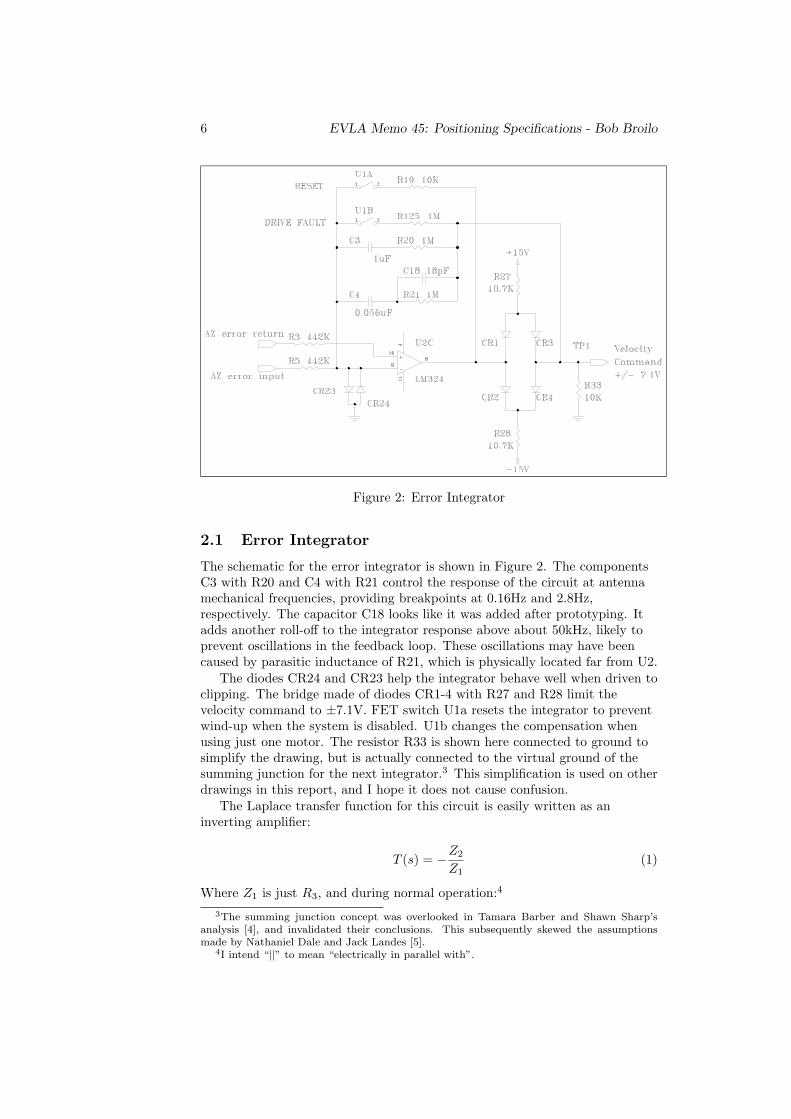
Figure 2: Error Integrator
2.1 Error Integrator
The schematic for the error integrator is shown in Figure 2. The componentsC3 with R20 and C4 with R21 control the response of the circuit at antennamechanical frequencies, providing breakpoints at 0.16Hz and 2.8Hz,respectively. The capacitor C18 looks like it was added after prototyping. Itadds another roll-off to the integrator response above about 50kHz, likely toprevent oscillations in the feedback loop. These oscillations may have beencaused by parasitic inductance of R21, which is physically located far from U2.
The diodes CR24 and CR23 help the integrator behave well when driven toclipping. The bridge made of diodes CR1-4 with R27 and R28 limit thevelocity command to ±7.1V. FET switch U1a resets the integrator to preventwind-up when the system is disabled. U1b changes the compensation whenusing just one motor. The resistor R33 is shown here connected to ground tosimplify the drawing, but is actually connected to the virtual ground of thesumming junction for the next integrator.3 This simplification is used on otherdrawings in this report, and I hope it does not cause confusion.
The Laplace transfer function for this circuit is easily written as aninverting amplifier:
T (s) = −Z2
Z1(1)
Where Z1 is just R3, and during normal operation:4
3The summing junction concept was overlooked in Tamara Barber and Shawn Sharp’sanalysis [4], and invalidated their conclusions. This subsequently skewed the assumptionsmade by Nathaniel Dale and Jack Landes [5].
4I intend “||” to mean “electrically in parallel with”.

EVLA Memo 45: Positioning Specifications - Bob Broilo 7
Z2 =(
1C4s
+1
1R21 + C18s
)||(R20 +
1C3s
)(2)
I started evaluating (1) by hand, but at some point realized how silly that wasand let the math package Maple do the work. (2) becomes:
Z2 =(1 + (C18R21 +R21C4)s)(1 +R20C3s)
s(C4 + C3 + (C4C18R21 +R20C3C4 + C3C18R21 +R21C3C4)s+R20R21C3C4C18s2)(3)
Plugging in the component values into (3) and evaluating (1), the transferfunction for the error integrator (in azimuth) is:
Terr(s) = −282(5.00× 10⁵ + 2.80× 10⁴s)(s+ 1)s(7.00× 10⁶s+ 6.6× 10⁷ + 63.0s2)
(4)
And factoring to see the poles and zeroes:
Terr(s) = −1.26× 10⁵ (s+ 17.9)(s+ 1)s(s+ 1.11× 10⁵)(s+ 9.43)
(5)
The only difference in elevation is that R3 and R5 are replaced with R4and R6, which are 100K. Using (1), (4) becomes:
Terr(s) = −1250(5.00× 10⁵ + 2.80× 10⁴s)(s+ 1)s(7.00× 10⁶s+ 6.6× 10⁷ + 63.0s2)
(6)
For the elevation axis.
8 EVLA Memo 45: Positioning Specifications - Bob Broilo
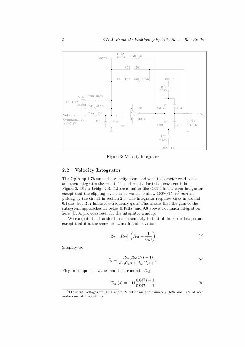
Figure 3: Velocity Integrator
2.2 Velocity Integrator
The Op-Amp U7b sums the velocity command with tachometer read backsand then integrates the result. The schematic for this subsystem is inFigure 3. Diode bridge CR9-12 are a limiter like CR1-4 in the error integrator,except that the clipping level can be varied to allow 100%/150%5 currentpulsing by the circuit in section 2.4. The integrator response kicks in around0.18Hz, but R52 limits low-frequency gain. This means that the gain of thesubsystem approaches 11 below 0.18Hz, and 9.8 above; not much integrationhere. U13a provides reset for the integrator windup.
We compute the transfer function similarly to that of the Error Integrator,except that it is the same for azimuth and elevation:
Z2 = R52||(R51 +
1C5s
)(7)
Simplify to:
Z2 =R52(R51C5s+ 1)
R51C5s+R52C5s+ 1(8)
Plug in component values and then compute Tvel:
Tvel(s) = −110.887s+ 10.997s+ 1
(9)
5The actual voltages are 10.8V and 7.1V, which are approximately 162% and 106% of ratedmotor current, respectively.

EVLA Memo 45: Positioning Specifications - Bob Broilo 9
Figure 4: Buffer Amplifier and Absolute Value Circuit
No surprises here, general gain of 11 and close pole/zero pair on the real axis.So close, in fact, that they almost null each other. Again, not muchintegration going on in this circuit.
2.3 Buffer Amplifier and Absolute Value Circuit
Two circuits are illustrated in Figure 4: the buffer amplifier and the absolutevalue circuit. The buffer is a simple integrator with a gain limit of 1 and a 3dBfrequency of 20Hz. The transfer function is:
Tbuf(s) =R81||
(1
C17s
)R74
=R81
(R81C17s+ 1)R74=
11 + 0.0056s
(10)
The output from the buffer circuit on TP9 is the current command. Themotor current delivered by the drive amplifier is 2.85A/V. Some importantvalues of this voltage are:
Current Motor RatedCommand Current Current
4.0V 11.5A 60% Threshold to apply preload4.3V 12.25A 65% Threshold to remove preload6.7V 19A 100%7.1V 20.2A 106% limit of velocity integrator, normal
10.0V 28.5A 150%10.8V 30.78 162% limit of velocity integrator, pulsed
The absolute value circuit just prepares the current command for use bythe Current Pulser and Preload subsystems. You should note that it imposesone diode voltage drop to the current command from diodes CR13 and CR14.This is OK, because the circuits that use the output value all have thresholdsof several volts.
For normal operation we can ignore this circuit in the transfer function.
10 EVLA Memo 45: Positioning Specifications - Bob Broilo
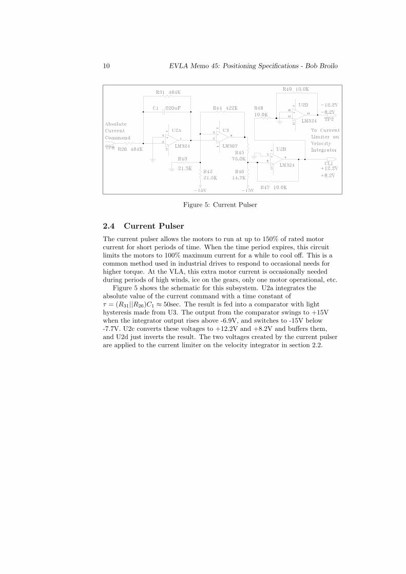
Figure 5: Current Pulser
2.4 Current Pulser
The current pulser allows the motors to run at up to 150% of rated motorcurrent for short periods of time. When the time period expires, this circuitlimits the motors to 100% maximum current for a while to cool off. This is acommon method used in industrial drives to respond to occasional needs forhigher torque. At the VLA, this extra motor current is occasionally neededduring periods of high winds, ice on the gears, only one motor operational, etc.
Figure 5 shows the schematic for this subsystem. U2a integrates theabsolute value of the current command with a time constant ofτ = (R31||R26)C1 ≈ 50sec. The result is fed into a comparator with lighthysteresis made from U3. The output from the comparator swings to +15Vwhen the integrator output rises above -6.9V, and switches to -15V below-7.7V. U2c converts these voltages to +12.2V and +8.2V and buffers them,and U2d just inverts the result. The two voltages created by the current pulserare applied to the current limiter on the velocity integrator in section 2.2.

EVLA Memo 45: Positioning Specifications - Bob Broilo 11
Figure 6: Preload Generator
2.5 Preload Generator
The preload generator, shown in Figure 6, creates the voltage offset to add andsubtract from the current commands sent to the two drives. U4 switches if thecurrent command increases above 4.3V6 Capacitor C6 provides a short delay7,and then capacitor C7 ramps the preload voltage down from 7.0V to 0V in 2.2seconds, removing the preload. If the current command drops below 4.0V8, C7then ramps the preload back up from 0V to 7V in 10 seconds, reapplying thepreload.
U7c is a simple inverter to apply the opposite preload to the other motor.
3 Inputs and Outputs
Complete input and output lists for both the ACU and F/R controller follow.There are a lot of signals, but most have simple functionality. For example,the motor temperature switch simply enables the drive fault flag for thatmotor. Many of the signals are for monitoring only.
3.1 ACU Inputs and Outputs
Most of the connections for the ACU are on the rear panel. All of the rearpanel connectors are military style circular connectors. The new ACU willlikely use mating circular connectors to allow a drop-in type replacement ofthe entire unit. These connectors are expensive but reliable. There are twofront panel connections, a meter test point and a military circular connectorfor the remote box.
Most of the systems external to the ACU will not be upgraded at this time,including the drive cabinet, limit switches, fire alarm, etc. This avoidsextensive re-wiring while upgrading the most critical part of the system.
The AC power for the ACU is 120V and comes in on a standardthree-prong grounded cord which is permanently mounted to the rear panel.
63.1V+2 diode drops7Somewhere around 3.75 seconds, but it’s highly variable82.8V+2 diode drops

12 EVLA Memo 45: Positioning Specifications - Bob Broilo
Any new system should use a fused power filter with standard removablecable, similar to that on the new encoder system [8].
3.1.1 J1 Coarse Synchro
J1 is an MS3112E20-16P military circular connector. This is where the coarsesynchro signals were input to run the rotational scales on the front of theACU. This connection is no longer used, as the position information is nowdisplayed on the new encoder system Data Receiver/Buffer (DRB).
3.1.2 J2 Interlocks, Limits
J2 is an MS3112E22-55P military circular connector. For the following pinlistings I used some shorthand9. The “connection” column in the list is wherethe signal goes internal to the ACU.
Pin Description Connection TypeA first AZ CW lim sw XA6 14 ID PU-1KB first AZ CW lim sw (NC) J4 DC sw GND GNDD 2nd AZ CW lim sw XA6 J, E4 ID PU-1KE 2nd AZ CW lim sw (NC) J4 AAF sw GND GNDG first AZ CCW lim sw XA6 11 ID PU-1KH first AZ CCW lim sw (NC) J4 EJ sw GND GNDK 2nd AZ CCW lim sw XA6 8, E3 ID PU-1KL 2nd AZ CCW lim sw (NC) J4 BBM sw GND GNDN first EL up lim sw XA6 21 ID PU-1KP first EL up lim sw (NC) J4 PR sw GND GNDS 2nd EL up lim sw XA6 27, E2 ID PU-1KT 2nd AZ CW lim sw (NC) J4 CCU sw GND GNDV first EL down lim sw XA6 24 ID PU-1KW sw GND GNDX first EL down lim sw (NC) J4 HHY sw GND GNDZ stow pin engaged sw XA6 30 ID PU-1Ka 2nd EL down lim sw XA6 /E, E1 ID PU-1Kb 2nd EL down lim sw (NC) J4 DDc sw GND GNDd E stop relay K1(XA6 33, E10) (ID PU-1K)e +24Vf N/Cg GNDh drive fault reset relay K2(TB1-4) (ID) (120V power)
9I-input O-output PU-pull up PD-pull down D-digital A-analog sw-switch lim-limit CW-clockwise CCW-counterclockwise NC-normally closed N/C-no connection ?-unknown

EVLA Memo 45: Positioning Specifications - Bob Broilo 13
i N/Cj ped room fan A11 BP2 14 ID TTLk GND E11 GNDm ?n ?p Ret BP2 11 GNDq Lead sw BP2 10 ID PU-1Kr N/Cs N/Ct N/Cu N/Cv Ret BP2 13 GNDw Lag sw BP2 12 ID PU-1Kx N/Cy N/Cz N/CAA ?BB N/CCC N/CDD N/CEE N/CFF N/CGG N/CHH N/C
3.1.3 J3 Tachometers, Temperatures
J3 is an MS3112E16-26PY military circular connector.
Pin Description Connection TypeA #1 AZ tach XA4 S IAB #1 AZ tach GND GNDC #1 AZ motor overtemp XA4 /B ID PU-1KD #2 AZ tach XA4 T IAE #2 AZ tach GND GNDF #2 AZ motor overtemp XA4 /C ID PU-1KG #1 EL tach XA5 S IAH #1 EL tach GND GNDJ #1 EL motor overtemp XA5 /B ID PU-1KK #2 EL tach XA5 T IAL #2 EL tach GND GNDM #2 EL motor overtemp XA5 /C ID PU-1KN #1 AZ motor overtemp ret GNDP #2 AZ motor overtemp ret GNDR #1 EL motor overtemp ret GNDS #2 EL motor overtemp ret GNDT Smoke det XA7 18, +5VU Smoke det J3 W, J3 NV Smoke det trouble 16 A11 CP1-2 ID TTLW Smoke det trouble 15 J3 U, J3 N

14 EVLA Memo 45: Positioning Specifications - Bob Broilo
X N/CY N/CZ N/Ca N/Cb N/Cc N/C
3.1.4 J4 Drive Cabinet
J4 is an MS3112E22-55P military circular connector. This is the connection tothe drive cabinet. The drive cabinet contains the current amplifiers.
Pin Description Connection TypeA #1 AZ disable XA6 S OD PDB #1 AZ current command + XA4 V OAC #1 AZ current command - XA4 18 GNDD first AZ CW lim sw (NC) J2 BE first AZ CCW lim sw (NC) J2 HF IM1A XA4 34, XA7 C IAG #2 AZ disable XA6 T OD PDH #2 AZ current command + XA4 W OAJ #2 AZ current command - XA4 19 GNDK IM2A XA4 33, XA7 F IAL #1 EL disable XA6 /A OD PDM #1 EL current command + XA5 V OAN #1 AZ current command - XA5 18 GNDP first EL up lim sw (NC) J2 NR IM1E XA5 34, XA7 K IAS #2 EL disable XA6 /BT #2 EL current command + XA5 W OAU #2 AZ current command - XA5 19 GNDV IM2E XA5 33, XA7 N IAW #1 AZ blower CB XA4 /F ID PU-1KX #2 AZ blower CB XA4 /H ID PU-1KY #1 AZ motor CB XA4 /D ID PU-1KZ #2 AZ motor CB XA4 /J ID PU-1Ka Cabinet Common #2 E16 GNDb #1 EL blower CB XA5 /F ID PU-1Kc #2 EL blower CB XA5 /H ID PU-1Kd #1 EL motor CB XA5 /D ID PU-1Ke #2 EL motor CB XA5 /J ID PU-1Kf CB Common E15 GNDg Brake relay +24V E10 +24Vh /AZ brake XA6 R OD PDi #1 AZ field monitor XA4 /E IAj #2 AZ field monitor XA4 /E IAk #1 EL field monitor XA5 /E IAm #2 EL field monitor XA5 /E IAn /EL brake XA6 /C OD PDp ?

EVLA Memo 45: Positioning Specifications - Bob Broilo 15
q Phase C XA7 /M IAr Phase B XA7 /J IAs Phase A XA7 /E IAt Cabinet Common #1 E15 GNDu Cab temp SW XA6 5 ID PU-1Kv N/Cw N/Cx N/Cy N/Cz N/CAA 2nd AZ CW lim sw (NC) J2 EBB 2nd AZ CCW lim sw (NC) J2 LCC 2nd EL up lim sw (NC) J2 TDD 2nd EL down lim sw (NC) J2 DDEE N/CFF N/CGG N/CHH first EL down lim sw (NC) J2 X
3.1.5 J5 and J6 Azimuth and Elevation Position Data
These are the 20-bit parallel position data connections from the DRB. Theseconnections should be abandoned and replaced with a serial connection, or thefiber data streams read directly with the new ACU.
3.1.6 J7 Data Set, Anemometers
J7 is an MS3112E12-10S military circular connector. This is the connection tothe existing M&C system.
Pin Description Connection TypeA /XMIT A11 BP2 6 OD DM8830 DLDB GND E16 GNDC Anemometer #1 A3 P1 14 IAD ?E DATA A11 BP2 2 ID LEDF /DATA A11 BP2 1 ID LEDG Anemometer #2 A3 P1 17 IAH XMIT A11 BP2 5 OD DM8830 DLDJ Anemometer #1 A3 P1 15 GNDK Anemometer #2 A3 P1 17 GND
3.2 F/R Controller Inputs and Outputs
The F/R Controller has many modules interconnected with many cables.These are already described in the manual [7]. What I attempt to do here islist the connections that need to be acquired by a new system.
Ideally, the F/R Controller would have only one data connection to theapex of the antenna, through a two-way fiber link. The translator, positionfeedback, switches, brakes, and temperature sensors would be housed at theapex with a simple power feed and fiber pair. However, EVLA phase 2 may

16 EVLA Memo 45: Positioning Specifications - Bob Broilo
require a complete redesign of the F/R mount, so major modifications to theapex system should wait.
I am going to design a compromise. I will replace only the M7E and M11modules with new electronics, but include the capability for simple fiber paircommunication with the apex. This modified scheme keeps only the simplestcomponents from the old system, and allows easy upgrades.
3.2.1 M7E P1
Many of these connections do not apply to an EVLA antenna.
Pin Description Connection TypeA +15VB Logic GNDC +5VD N/CE -15VF-y connections to M1, not needed for EVLAz Foc brake SSR A9 13 ODAA-HH antenna serial number, not needed for EVLA
3.2.2 M7E P2
This is where the front panel controls, translators, and power controls connect.
Pin Description Connection TypeA Foc cmd LED D22 29 ODB Foc brake LED D22 30 ODC Foc up lim LED B29 3 ODD Foc dn lim LED B29 5 ODE Foc xlator power LED A8 6 ODF Foc motor pulses LED D22 31 ODH Foc drv up LED B11 6 ODJ Foc drv dn LED B11 10 ODK Rot cmd LED D22 29 ODL Rot brake LED D22 30 ODM Rot pin in LED D22 32 ODN Rot CW lim LED B29 11 ODP Rot CCW lim LED B29 13 ODR Rot xlater power LED A8 10 ODS Rot motor pulses LED ?T Rot drv CW LED B21 6 ODU Rot drv CCW LED B21 10 ODV P Band LED D22 21 ODW L Band LED D22 22 ODX C Band LED D22 23 ODY U Band LED D22 24 ODZ K Band LED D22 25 ODa X Band LED D22 26 ODb Y Band LED D22 27 ODc Z Band LED D22 28 OD
EVLA Memo 45: Positioning Specifications - Bob Broilo 17
d Foc xlator drv up A23 2 OD 15Ve Foc xlator drv dn A23 4 OD 15Vf Foc xlator drv ret GNDh Foc xlator SSR A9 6 ODj Foc brake SSR A9 3 ODk Rot xlator drv CW A23 14 OD 15Vm Rot xlator drv CCW A23 12 OD 15Vn Rot xlator drv ret GNDp Foc xlator SSR A9 10 ODr Ring ext SSR B26 14 ODs Ring ret SSR B26 6 ODt Foc xlator power mon A1 2 IAu Rot xlator power mon A1 6 IAv Foc ramp switch PROM#2 32 IDw Foc drv up switch PROM#2 33 IDx Foc drv dn switch PROM#2 34 IDy Rot ramp switch PROM#2 32 IDz Rot drv CW switch PROM#2 33 IDAA Rot drv CCW switch PROM#2 34 IDBB Band switch 1 PROM#2 37 IDCC Band switch 2 PROM#2 38 IDDD Band switch 3 PROM#2 39 IDEE Band switch active PROM#2 36 IDFF Synchro Mon Hi A20 12 IAHH Synchro Mon Lo A20 8 GND
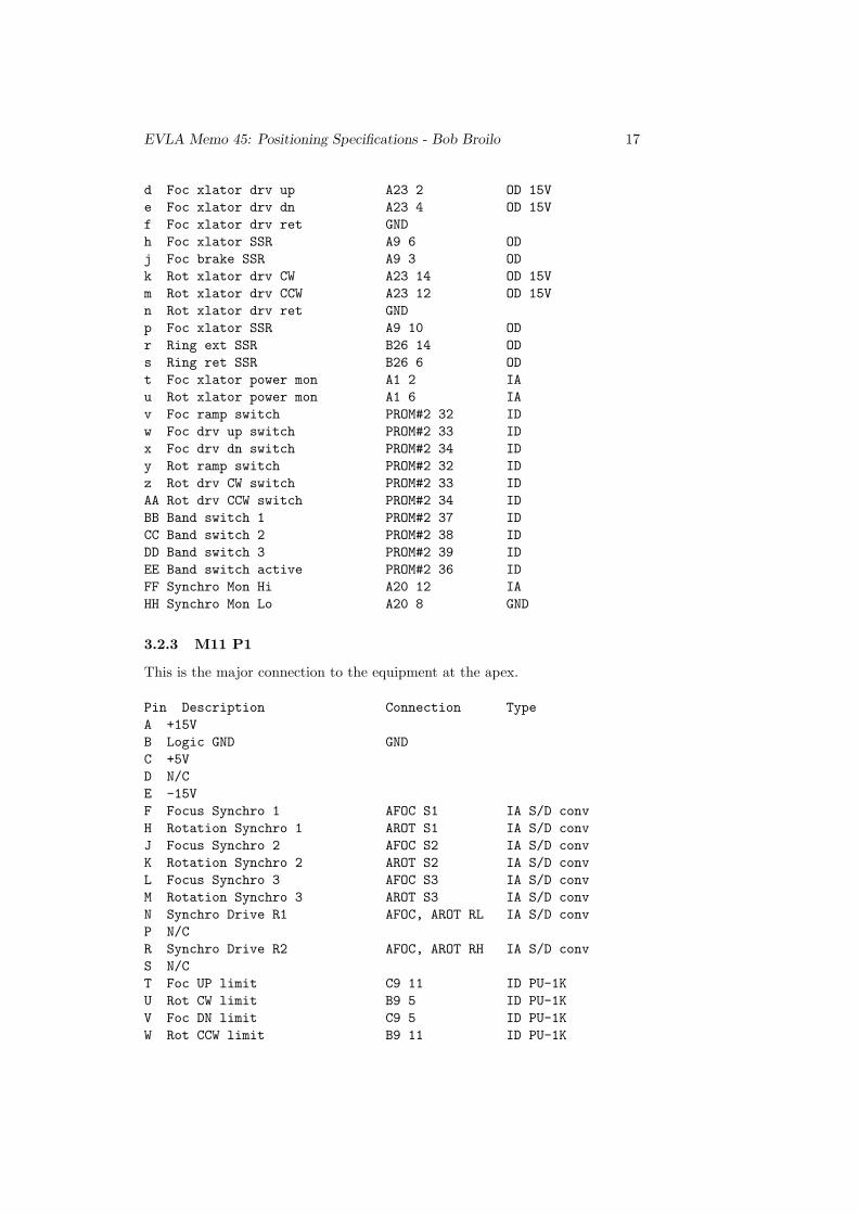
3.2.3 M11 P1
This is the major connection to the equipment at the apex.
Pin Description Connection TypeA +15VB Logic GND GNDC +5VD N/CE -15VF Focus Synchro 1 AFOC S1 IA S/D convH Rotation Synchro 1 AROT S1 IA S/D convJ Focus Synchro 2 AFOC S2 IA S/D convK Rotation Synchro 2 AROT S2 IA S/D convL Focus Synchro 3 AFOC S3 IA S/D convM Rotation Synchro 3 AROT S3 IA S/D convN Synchro Drive R1 AFOC, AROT RL IA S/D convP N/CR Synchro Drive R2 AFOC, AROT RH IA S/D convS N/CT Foc UP limit C9 11 ID PU-1KU Rot CW limit B9 5 ID PU-1KV Foc DN limit C9 5 ID PU-1KW Rot CCW limit B9 11 ID PU-1K
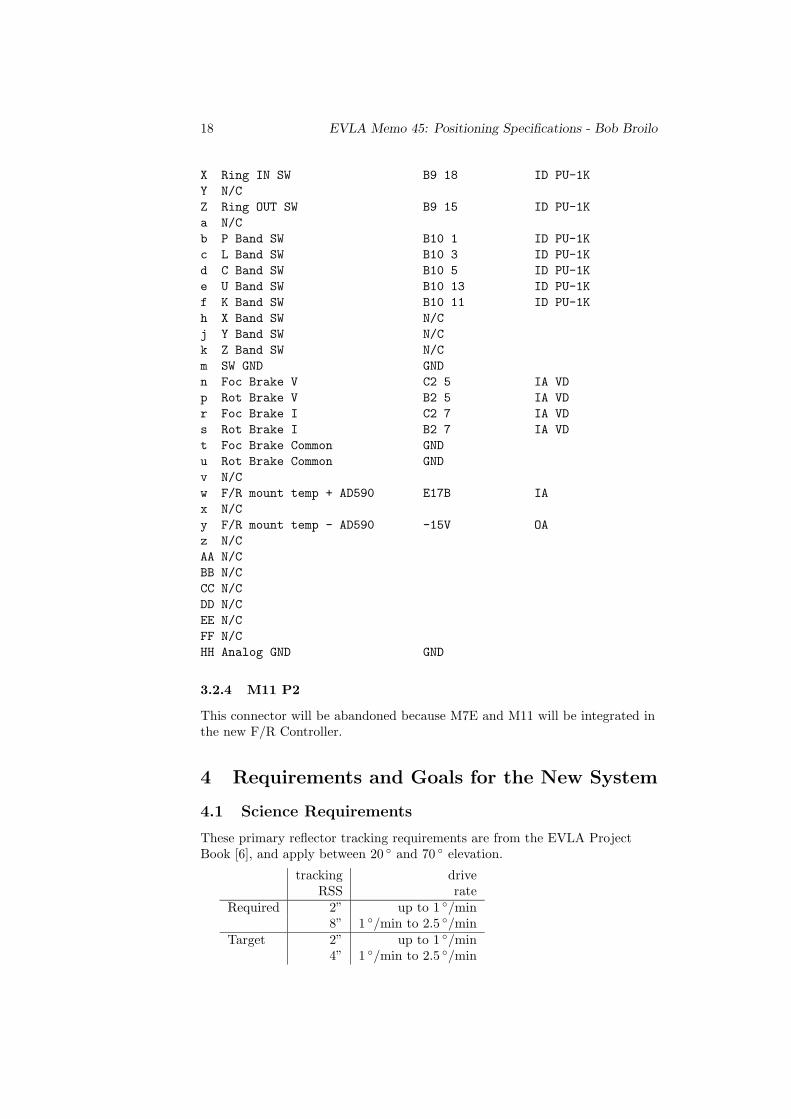
18 EVLA Memo 45: Positioning Specifications - Bob Broilo
X Ring IN SW B9 18 ID PU-1KY N/CZ Ring OUT SW B9 15 ID PU-1Ka N/Cb P Band SW B10 1 ID PU-1Kc L Band SW B10 3 ID PU-1Kd C Band SW B10 5 ID PU-1Ke U Band SW B10 13 ID PU-1Kf K Band SW B10 11 ID PU-1Kh X Band SW N/Cj Y Band SW N/Ck Z Band SW N/Cm SW GND GNDn Foc Brake V C2 5 IA VDp Rot Brake V B2 5 IA VDr Foc Brake I C2 7 IA VDs Rot Brake I B2 7 IA VDt Foc Brake Common GNDu Rot Brake Common GNDv N/Cw F/R mount temp + AD590 E17B IAx N/Cy F/R mount temp - AD590 -15V OAz N/CAA N/CBB N/CCC N/CDD N/CEE N/CFF N/CHH Analog GND GND
3.2.4 M11 P2
This connector will be abandoned because M7E and M11 will be integrated inthe new F/R Controller.
4 Requirements and Goals for the New System
4.1 Science Requirements
These primary reflector tracking requirements are from the EVLA ProjectBook [6], and apply between 20 ◦ and 70 ◦ elevation.
tracking driveRSS rate
Required 2” up to 1 ◦/min8” 1 ◦/min to 2.5 ◦/min
Target 2” up to 1 ◦/min4” 1 ◦/min to 2.5 ◦/min

EVLA Memo 45: Positioning Specifications - Bob Broilo 19
At high elevations, the azimuth velocity increases:
ωAZ =ωtrackingcos θEL
(11)
Using the worst-case conditions of 2.5 ◦/min @ 70 ◦ elevation, (11) gives amaximum required azimuth velocity of 7.3 ◦/min. The existing system has amaximum velocity of 40 ◦/min, so there is plenty of speed. To make sure thatthe antenna is where it is supposed to be, the position encoder needs to bechecked more often than 4”/2.5 ◦/min ≈ 27ms. The sample period should behalf that10 or about 13ms11. Although there is doubt that the antenna canactually physically wander that quickly, the new encoders [8] output dataevery 0.6ms, easily meeting the sampling requirement. The encoders areaccurate to better than 0.7”.
The antenna settling times for a 30’ motion need to be:Required < 5secTarget < 3sec
Experimentation on VLA antennas gave these results for a 31.6’12 motionto settle to 6”:
Azimuth 8 secondsElevation 4 seconds
The existing system does not meet the required performance, and is far fromthe target specification. Most of the settling time is spent oscillating afterovershooting the desired position. Since the new system will initially use theexisting loop transfer function, it will behave similarly. However, by addingsome derivative to the PI loop, we may be able to improve the settling timewithout compromising the stability. This would be a temporary fix until theloop process is refined.13
4.2 Safety and Operational Requirements
The requirements are listed in decreasing order of importance. Compromiseswill be made to ensure the primary requirements are met most completely.
4.2.1 Safety: People and Antenna
The primary E-Stop is the collection of red mushroom-head type switchesplaced in accessible locations all over the antenna. This system needs todisable both azimuth and elevation axes, preferably also removing power fromthe SCR motor drives and setting the brakes. The most important function ofthis system to to provide an immediate stop of the antenna in the event ofdanger to personnel or property damage. A secondary use is to prevent injuryor damage while maintenance is performed on the antenna. The E-Stop can beactivated remotely by operations, but if locally set, cannot be cleared remotely.
10To meet the Nyquist criterion11We can use the 13ms time period as a maximum latency in the loop software between
position calculations.12bits 10 and 1113This would be a good project for a Masters Electrical Engineering/Robotics/Mechanical
Engineering student
20 EVLA Memo 45: Positioning Specifications - Bob Broilo
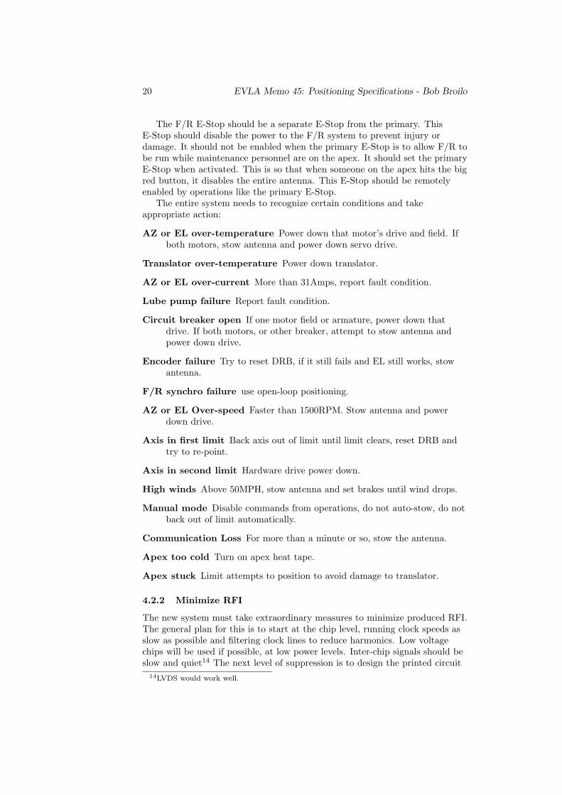
The F/R E-Stop should be a separate E-Stop from the primary. ThisE-Stop should disable the power to the F/R system to prevent injury ordamage. It should not be enabled when the primary E-Stop is to allow F/R tobe run while maintenance personnel are on the apex. It should set the primaryE-Stop when activated. This is so that when someone on the apex hits the bigred button, it disables the entire antenna. This E-Stop should be remotelyenabled by operations like the primary E-Stop.
The entire system needs to recognize certain conditions and takeappropriate action:
AZ or EL over-temperature Power down that motor’s drive and field. Ifboth motors, stow antenna and power down servo drive.
Translator over-temperature Power down translator.
AZ or EL over-current More than 31Amps, report fault condition.
Lube pump failure Report fault condition.
Circuit breaker open If one motor field or armature, power down thatdrive. If both motors, or other breaker, attempt to stow antenna andpower down drive.
Encoder failure Try to reset DRB, if it still fails and EL still works, stowantenna.
F/R synchro failure use open-loop positioning.
AZ or EL Over-speed Faster than 1500RPM. Stow antenna and powerdown drive.
Axis in first limit Back axis out of limit until limit clears, reset DRB andtry to re-point.
Axis in second limit Hardware drive power down.
High winds Above 50MPH, stow antenna and set brakes until wind drops.
Manual mode Disable commands from operations, do not auto-stow, do notback out of limit automatically.
Communication Loss For more than a minute or so, stow the antenna.
Apex too cold Turn on apex heat tape.
Apex stuck Limit attempts to position to avoid damage to translator.
4.2.2 Minimize RFI
The new system must take extraordinary measures to minimize produced RFI.The general plan for this is to start at the chip level, running clock speeds asslow as possible and filtering clock lines to reduce harmonics. Low voltagechips will be used if possible, at low power levels. Inter-chip signals should beslow and quiet14 The next level of suppression is to design the printed circuit
14LVDS would work well.

EVLA Memo 45: Positioning Specifications - Bob Broilo 21
board very carefully, using proper ground and RFI reduction techniques.Off-board lines must be properly routed and filtered. Finally, the metal boxthat houses the system needs to have the provision for RF gasketing and I/Oconnector filtering.
Due to the slow overall speed of the system’s I/O, the primary source of RFradiation will be the MIB. We may be able to mount the MIB as a sub-card tothe main board, with a small shield around it and lines filtered. If this controlsthe RFI acceptably then we could leave the overall housing of the systemopen. This improves the serviceability of the system drastically and eliminatesthe consequences of maintenance personnel not securing the lid to the housing.
The system will need to be RFI tested in a standard manner similarly toother EVLA modules.
4.2.3 Protection from Electro-static Discharge (ESD)
When the original ACU was built, TTL ruled the day. This technologydominated the design and production of the equipment. This makes the unitfairly robust in terms of immunity to damage or error by ESD.
The new ACU will be almost completely MOS technologies. While modernMOS chips are somewhat protected from ESD by diodes on inputs, there arestill important design guidelines that will improve reliability.
All digital inputs must be terminated with pull-up or pull-down resistor of10-100K. This prevents nasty latch-up, and also keeps operation predictableand power use down. This is especially important for lines leading to externalconnectors, because the lines may be disconnected at any time.
The system will be housed in a metal box with proper AC power safetygrounding. This prevents ESD currents from traveling through the systemcircuits, and reduces the susceptibility of signal lines to nearby staticdischarges.
Another form of ESD that needs attention is lightning. The VLA antennassuffer direct lightning strikes. Most of the signals to the system will be fromthe elevation platform and pedestal room. These are well protected by theantenna structure and do not need further lightning protection.15
There are a few signals that will need to be carefully considered. The wiresthat connect the system to the F/R mount and E-Stop at the apex areobviously at risk from lightning. The anemometers are at the edge of the dishand are therefore very exposed. The existing F/R Controller usesopto-isolation between the M11 and M7E modules to help protect themicroprocessors. However, the use of proper grounding techniques withadequate surge suppression should be enough to protect these lines.16
15The existing ACU does not suffer lightning-related failures and has no lightning protection.16The ideal strategy would eliminate the signal cables and large stepper motor wires going
to the apex and use a Fiber Cable. We would need to move the translators to the apex toaccomplish this. Moving the translators would be very costly and beyond the requirements ofEVLA as it is funded now. However, it would reduce RFI and eliminate many cable failuresas well as protect the system from lightning. If the FRM is redesigned in a future upgrade,the interface should be simplified as discussed in Section 3.2.
22 EVLA Memo 45: Positioning Specifications - Bob Broilo
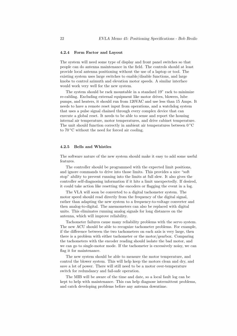
4.2.4 Form Factor and Layout
The system will need some type of display and front panel switches so thatpeople can do antenna maintenance in the field. The controls should at leastprovide local antenna positioning without the use of a laptop or tool. Theexisting system uses large switches to enable/disable functions, and largeknobs to control azimuth and elevation motor speeds. A similar interfacewould work very well for the new system.
The system should be rack mountable in a standard 19” rack to minimizere-cabling. Excluding external equipment like motor drives, blowers, lubepumps, and heaters, it should run from 120VAC and use less than 15 Amps. Itneeds to have a remote reset input from operations, and a watchdog systemthat uses a pulse signal chained through every complex device that canexecute a global reset. It needs to be able to sense and report the housinginternal air temperature, motor temperatures, and drive cabinet temperature.The unit should function correctly in ambient air temperatures between 0 ◦Cto 70 ◦C without the need for forced air cooling.
4.2.5 Bells and Whistles
The software nature of the new system should make it easy to add some usefulfeatures.
The controller should be programmed with the expected limit positions,and ignore commands to drive into those limits. This provides a nice “softstop” ability to prevent running into the limits at full slew. It also gives thecontroller self-diagnosing information if it hits a limit unexpectedly. If desired,it could take action like resetting the encoders or flagging the event in a log.
The VLA will soon be converted to a digital tachometer system. Themotor speed should read directly from the frequency of the digital signal,rather than adapting the new system to a frequency-to-voltage converter andthen analog-to-digital. The anemometers can also be replaced with digitalunits. This eliminates running analog signals for long distances on theantenna, which will improve reliability.
Tachometer failures cause many reliability problems with the servo system.The new ACU should be able to recognize tachometer problems. For example,if the difference between the two tachometers on each axis is very large, thenthere is a problem with either tachometer or the motor/gearbox. Comparingthe tachometers with the encoder reading should isolate the bad motor, andwe can go to single-motor mode. If the tachometer is excessively noisy, we canflag it for maintenance.
The new system should be able to measure the motor temperature, andcontrol the blower system. This will help keep the motors clean and dry, andsave a lot of power. There will still need to be a motor over-temperatureswitch for redundancy and fail-safe operation.
The MIB will be aware of the time and date, so a local fault log can bekept to help with maintenance. This can help diagnose intermittent problems,and catch developing problems before any antenna downtime.

EVLA Memo 45: Positioning Specifications - Bob Broilo 23
5 The Plan
Summarizing Section 3, we have the following minimum number of I/O lines:ACU F/R Total
Digital Inputs 30 21 51Digital Outputs 7 39 46Analog Inputs 17 16 33Analog Outputs 4 15 19
Many functions have simple logic that are inefficient to write computerprograms for and should not depend on a microprocessor to operate. Thisencourages the use of programmable logic. However, the display andfloating-point calculation aspects of the operation are best done with amicroprocessor.
The standard interface for all EVLA antennas will be the Module InterfaceBoard (MIB) [3], which has a powerful microprocessor17. There will be a MIBfor each subsystem to provide the Ethernet interface to the new M&C system.Some of the processing power of the MIB will be available for ACU and F/Rwork, so it will serve as a fine computational unit. The MIB will do thecommunication to and from the M&C system, calculate the servo loopcompensation18, drive the LCD display, enforce software limits, and dotemperature setpoint calculations. The position data from the encoders is 25bits, so a 32-bit data path for position data should be used.
The dozens of digital I/O lines can be handled with programmable logic.The programmable logic can communicate to the MIB with SPI, memoryaddressing, or other standard bus system. The logic gives us auto-stow, limits,and shutdowns even if the MIB ceases to function, or if we want some type ofmanual control system that disables the MIB control connection. The logicshould drive some LEDs for basic status indication.
If the programmable logic is field reconfigurable or programmable, then theentire functionality of the ACU or F/R Controller can be easily changed in thefuture. We can design the board with an open-ended strategy so that newcomponents, monitoring, and subsystems can be added without creating newcircuit boards and extensive re-wiring.
If the drives for either Azimuth and Elevation or FRM are ever upgraded,the new system should provide an easy path to interface with them.
The fiber receivers in the DRB are serviced by tiny microprocessors19
which could be replaced by state machines in the programmable logic. Thiswould further reduce the complexity and chip count in the system. The finaldecision on this option would need an approximate gate count to implementthe fiber receiver.
The analog I/O is all low bandwidth20 and can be easily done with SPI busA/D and D/A chips. These are readily available and cheap. It also makes iteasy to add capability in the future by adding more chips.
17At this time the proposed microprocessor is a 96MHz TRICore with at least 1.5MB RAMon board running an RTOS [2]
18Probably a C or C++ subroutine called at a fixed rate. This makes it easy to upgradethe loop calculation in the future.
19“Picoprocessors”: PIC16C55 chips.20100Hz sounds like a nice round number that is nice and slow but still gives a lot of room
for future improvements

24 EVLA Memo 45: Positioning Specifications - Bob Broilo
Figure 7: Concept for the new ACU and F/R system
Reset capability at the AC power supply level is desirable. There should besome SSRs21 added with one-shot timers on them. This would allow thesystems to do a cold-boot type reset triggered either by watchdog or Wyecomsignals. This strategy will save down-time and after hours call-outs to dopower resets.
Figure 7 is a concept view for the new system.
21Inspired by the F/R system[7]

EVLA Memo 45: Positioning Specifications - Bob Broilo 25
6 Notes
This document was prepared with GNU Emacs 20.2.1, LATEX 2εVersion3.14159 (Web2C 7.3.1), pdfLATEX 2εVersion 3.14159-13d (Web2C 7.3.1), anddvips 5.86 on Sun Solaris 2.5.1. I got relief from tedious algebra with Maple 7(IBM INTEL LINUX) on Linux: kernel version 2.2.19. The figures and circuitmodeling were done with OrCAD Capture 9.1, AutoCAD LT 98, andElectronics Workbench 5.12 on Windows NT 4.0 SP6.
Thanks to those who helped with ideas, advice, and inspiration: DaveAlderman, Walter Brisken, Barry Clark, Tom Frost, Clint Janes, WayneKoski, and Lew Serna.
References
[1] Electrospace Systems, Inc.: 93C-4 Antenna Control System, Maintenanceand Operating Manual, Very Large Array 25 Meter Antenna, Part#98D20000, (Richardson, TX: Omega-T Division, Electrospace Systems,Inc. 1975)
[2] W. M. Koski, G. Peck EVLA Monitor and Control Group: ModuleInterface Board Hardware Definition (Socorro, NM: National RadioAstronomy Observatory, 2002)
[3] W. Koski, R. Moeser, G. Peck, J. Robnett, B. Rowen, K. Ryan and W.Sahr EVLA Monitor and Control System (Socorro, NM: National RadioAstronomy Observatory, 2002)
[4] Tamara Barber, Shawn Sharp: VLA Electronics Memorandum #234:Characterization of the VLA Servo System (Socorro, NM: National RadioAstronomy Observatory, 1999)
[5] Nathaniel Dale, Jack Landes: VLA Expansion Project Memorandum #38:Design of a Motion Controller for VLA Antenna Azimuth and Elevation(Socorro, NM: National Radio Astronomy Observatory, 2000)
[6] R. Perley: EVLA Project Book, Chapter 2: Science (Socorro, NM:National Radio Astronomy Observatory, 2002)http://www.aoc.nrao.edu/evla/admin/projbook/chap2.pdf
[7] D. Weber, P. Harden, W. Koski: VLA Technical Report #56,Focus/Rotation Control System, Model E (Socorro, NM: National RadioAstronomy Observatory, 1984)
[8] Bob Broilo: VLA Technical report #76, Absolute Position EncoderElectronics Upgrade (Socorro, NM: National Radio AstronomyObservatory, 2000)http://www.aoc.nrao.edu/~bbroilo/encoder_report/encoder.html