evolution - krell industries contents list of tables and illustrations, page 4 a letter from dan...
TRANSCRIPT
OWNER’S REFERENCE
EVOLUTION
E V O L U T I O N 5 0 5
S A C D / C D P L AY E R
THE LEADER IN AUDIO ENGINEERING

Evolution 505 SACD/CD Player Owner’s Reference, v06.0
Krell Industries, Inc.45 Connair RoadOrange, CT 06477-3650 USA
This product complies with the EMC directive (89/336/EEC) and the low-voltage directive(73/23/EEC).
IMPORTANT SAFETY INSTRUCTIONS1. Read Instructions.
2. Keep these Instructions.
3. Heed all Warnings.
4. Follow all Instructions.
5. Do not use this apparatus near water.
6. Clean only with dry cloth.
7. Do not install near any heat sources such as radiators, heat registers, stoves, or other appa-ratus (including amplifiers) that produce heat.
8. Unplug this apparatus during lightning storms or when unused for long periods of time.
9. Refer all servicing to qualified service personnel. Servicing is required when the apparatushas been damaged in any way, such as a power-supply cord or plug is damaged, liquid hasbeen spilled or objects have fallen into the apparatus, the apparatus has been exposed torain or moisture, does not operate normally, or has been dropped.
10. Caution: Visible and invisible laser radiation. When the cover is open, avoid exposure to thebeam. This apparatus employs a laser. To prevent possible eye injury, only a qualified serviceperson should remove the cover, or attempt to service this apparatus. Use of controls oradjustments or performance of procedures other than specified herein may result in hazardouslaser radiation exposure.
11. The apparatus must be placed on a firm, level surface where it is not exposed to dripping orsplashing.
12. The ventilation grids on the top of the apparatus and the space underneath it must be unob-structed at all times during operation. Do not place flammable material above or beneath theapparatus.
13. Before making connections to the Evolution 505, ensure that the power is off and other compo-nents are in mute or stand-by mode. Make sure all cable terminations are of the highest quality,free from frayed ends, short circuits, or cold solder joints.
14. THERE ARE NO USER SERVICEABLE PARTS INSIDE AN EVOLUTION 505 SACD/CDPLAYER.
Please contact Krell if you have questions not addressed in this guide.
This product is manufactured in the United States of America. Krell® is a registered trademark of Krell Industries, Inc., and is restricted for use byKrell Industries, Inc., its subsidiaries, and authorized agents. Evolution Bias™ is a trademark of Krell Industries, Inc. and is a Krell technologybased on U.S. Patent No. 5,331,291. CAN Link™, CAST™, Evolution CAST™, and Krell Current Mode™ are trademarks of Krell Industries,Inc. All other trademarks are registered to their respective companies.
© 2006 by Krell Industries, Inc. All rights reserved P/N 309405-W
TEL 203-298-4000FAX 203-891-2028E-MAIL [email protected] http://www.krellonline.com

3
ContentsList of Tables and Illustrations, page 4
A Letter from Dan D’Agostino, page 5
SECTION ONE: Evolution 505 Features and Technology, page 6
Features, Revolutionary Krell CAST Technology,Definition of Terms
SECTION TWO: Unpacking and Placement, page 11
Opening the Evolution 505 Shipping Carton, Placement, AC Power Guidelines
SECTION THREE: Anatomy of the Evolution 505, page 13
Front Panel Description, Remote Control Description, Battery Installation andRemoval, Back Panel Description
SECTION FOUR: Connecting the Evolution 505 to Your System, page 22
Using Balanced Connections, Connection Steps
SECTION FIVE: Evolution 505 Operation, page 24
Power On, How to Play a Disc, Disc Formats, Data Disc, Filter, Repeat Functions, 12 VDC Trigger, RS-232 Port
WARRANTY, page 28
RETURN AUTHORIZATION PROCEDURE, page 30
SPECIFICATIONS, page 31

4
List of Illustrations and TablesFigure 1, page 13
Evolution 505 Front Panel
Figure 2, page 17Evolution 505 Remote Control
Figure 3, page 19Evolution 505 Back Panel
Table 1, page 22Analog and Digital Connections

5
A Letter from Dan D’Agostino
Dear Audio Enthusiast,
Thank you for your purchase of the Krell Evolution 505 SACD/CD Player. Sourcecomponents are the first, vital link in the audio signal chain, and an audio systemcan perform no better than the source allows. For this reason, I have made everyeffort to include the best technology in the design of this new Krell product.
At the heart of the Evolution 505 are separate, linear power supplies that insureperfect operating conditions for the drive mechanism and audio circuits. Discrete,Class A gain stages are balanced and are utilized from input to output. CurrentMode topologies enable wide bandwidth performance, while Current Audio SignalTransmission (CAST) transmitters insure the most robust connection to otherEvolution components. All of these technologies are heard in the authentic andsatisfying audio reproduction of the Evolution 505.
I hope that you enjoy your new Evolution 505 source component.
Sincerely,
Daniel D’Agostino
Chief Executive Officer

6
SECTION ONEEvolution 505 Features and Technology
This section describes the innovative features and technology of the Evolution 505SACD/CD Player, and defines CAST and other key terms used in this reference.
The Evolution 505 works to carefully transmit audio signals without damaging theephemeral staging and dimensional components of the music. A combination ofadvanced technologies and inspired design elevate the Evolution 505 SACD/CDPlayer’s performance to the reference level.
Features
The Evolution 505 has Class A, balanced, Krell Current Mode topology from inputto output for increased bandwidth. New current mirror stages feature LED voltagereference. Developed for the Evolution Two, these current mirrors operate withthree times less distortion than previous designs. A zero feedback design pre-serves the original harmonic structure of the recording, and a 500 K bandwidthpromotes low distortion and phase coherent performance.
The Evolution 505 uses PCM 1738 differential advanced segment DACs for supe-rior dynamic range, and a DCI drive with independent suspension for enhancedergonomics and reliability.
The Evolution 505 will read redbook, CDR, 44.1 WAV, AAC (adts, and adif), DVD-R, RW, +R, and RW discs. The 16 character, dot-matrix LED display is highly visi-ble and features an adjustable intensity.
For flexibility of control, the back panel features a 2-way, RS-232 interface, anRC-5 connector, and 12 VDC trigger inputs and outputs. Krell Can Link connec-tors allow the Evolution 505 to operate in link mode with other Evolution compo-nents.
The outputs include balanced XLR, single-ended multi-channel outputs, and a pairof Evolution CAST™ outputs, for the most robust connection to other Evolutioncomponents.
A 65 VA linear power supply is used for the drive mechanism, for absolute voltagestability. A separate 45 VA linear power supply for the audio circuits is optimized topower critical Class A audio topologies.

7
Revolutionary Krell CAST TechnologyCurrent Audio Signal Transmission, termed CAST, is a revolutionary method ofconnecting analog audio components for unparalleled sonic performance.Innovative engineering combines the new Krell CAST circuitry with existing KrellCurrent Mode technology to create entire CAST systems that reproduce musicwith incredible range, tonality, and precision.
The Voltage Signal Transmissionand the Traditional Audio System
Traditionally, signal is transmitted in the voltage domain between two components.In an audio system, each component is a discrete entity with unique characteris-tics that act upon the musical signal independently. Each component is unawareof the other components in the system. The cables that connect the componentsalso have their own electrical characteristics, which affect the sonic presentationof the entire system. CAST transmission unifies individual components and inter-connects into an electrically-linked whole. The original signal remains unalteredfrom source to speaker.
CAST Basics
Here is how a CAST audio system works: Internally, each CAST source transfers,or amplifies, current using Krell Current Mode circuitry. This current signal is thenoutput using CAST circuitry. When the signal is received by a CAST input, KrellCurrent Mode circuitry again takes over until the signal reaches the loudspeaker.By maintaining the musical signal in the current domain from beginning to end, anentire CAST system behaves as if it is one component. With CAST, circuit boardproperties and signal transmission aberrations between components are eliminat-ed. Cable impedances and their effects on the transmitted signal are non-existent.
How CAST and Krell Current Mode Interact
While CAST is a new method of transferring the musical signal between compo-nents, its origin stems from Krell Current Mode, the technology developed totransfer the musical signal within a component. CAST combined with Krell CurrentMode takes circuitry signal transmission to the next evolutionary level.
continued

8
In essence, Krell Current Mode maintains the integrity of the signal within thecomponent and CAST preserves the transmitted signal between components.Together, CAST and Krell Current Mode technologies unify separate Krell compo-nents into a single global circuit. Krell Current Mode technology enjoys bandwidthincreases up to an order of magnitude greater than their voltage based counter-parts. This dramatic increase in circuit bandwidth delivers near perfection in theaudible band that typically suffers from phase distortions in voltage circuits.
CAST Cable Construction
A CAST system uses cables manufactured by Krell and other manufacturers spe-cially licensed by Krell. Thin and flexible CAST cables are constructed with thesame build quality as other Krell components and are aesthetically matched to thecomponents that Krell manufactures. An all-metal body and locking connectorswith gold contacts are part of the standard no-compromise specification devel-oped for every CAST cable made.
Evolution CAST
By employing radical current mirror circuitry, the Evolution 505 components ele-vate the CAST technology to another level. This advanced use of the technologyincreases the linearity, transient speed, and bandwidth of the Evolution compo-nents while reducing the distortion by an order of magnitude.
The Best Musical Performance
When you operate a CAST system, you will hear significant improvements in everyperformance area: speed, precision, dynamic range, depth and width of the soundstage, transient impact, tonal balance, harmonic distortion, and more. The goal forCAST is the same company goal used for all Krell products. Krell strives for thedelivery of the best performance of a musical event for you, using the full expres-sion of technology to date.
(SECTION ONE: Evolution 505 Features and Technology continued)

9
Definition of TermsThe following are definitions of key terms used in this owner’s reference:
Inputs and Outputs
BalancedA symmetrical input or output circuit that has equal impedance from both input terminals to a common ground reference point. The industry standard for profes-sional and sound recording installations, balanced connections have 6 dB moregain than single-ended connections and allow the use of long interconnect cables.Balanced connections are completely immune to induced noise from the systemor the environment.
CAST and Evolution CASTKrell Current Audio Signal Transmission, or CAST, is a proprietary Krell circuit tech-nology for connecting analog components, transmitting the audio waveformbetween components in the current domain rather than in the voltage domain. Thespeed and bandwidth provided by Krell CAST and its circuitry update, EvolutionCAST, yield accurate, realistic music reproduction, enabling connected compo-nents to perform as if they are all part of a single circuit.
Single-endedA two-wire input or output circuit. Single-ended connections are not recommend-ed for connections requiring long cable runs. Use care when using single-endedconnections, because the ground connection is made last and broken first. Turnthe system off/on prior to making or breaking single-ended connections.
Operation
OffWhen the back panel power switch (34) is in the down (0) position, or the ACpower supply cord is disconnected, the component is off, and the stand-by/powerLED is not illuminated.
Stand-byA low-power-consumption status that keeps the audio and regulator circuits atidle. The stand-by/power LED (2) is illuminated in red when the component is instand-by mode. Krell recommends leaving the component in stand-by mode whenit is not playing music.
OperationWhen the power button (1) or key is pressed, the standby/power LED (2) is illumi-nated in blue, and the component is in operational mode and ready to play music.
continued

10
Technology
Krell Current ModeA proprietary Krell circuit topology in which the audio gain stages of a componentoperate in the current rather than the voltage domain. This unique technology pro-vides the component with exceptional speed and a wide bandwidth.
SACD DiscA Super Audio Compact Disc (SACD) is an audio disc that provides exceptionalhigh quality sound. Based on the new Direct Stream Digital (DSD) technology, aformat that comprises a 1-bit system, a SACD has a sampling frequency 64 timeshigher than that of a conventional audio CD. With a frequency response of over50 kHz, and a dynamic range of 120 dB over the entire audible spectrum, theresults are spectacular: There is no better audio disc reproduction.
You will recognize a SACD by the super audio compact disc logo.There are three SACD disc types:
1. A single layer disc consists of one high density (HD) layer.2. A dual layer disc consists of two HD layers, and can store twice as much infor-
mation as a single layer disc.3. A hybrid disc consists of one standard compact disc layer with conventional
two-channel audio compact disc information, and one HD layer.
SACD Disc: Hybrid Disc TypeEach SACD disc type may contain two areas of recorded information: a high-quali-ty two-channel area and a high-quality multi-channel area. Recorded informationmay vary per area. Refer to the disc inlay for more information.
The hybrid SACD disc type has the most versatile disc playback options, with twoareas of recorded information for SACD playback as well as backward compatibili-ty with existing standard CD and DVD players via the standard compact disc layer.
On a hybrid SACD disc, the two layers are read from the same side of the disc.The HD layer is read by a DVD laser. The reflective conventional compact disclayer is read by the CD laser through the second, semi-transmissive HD layer.
CDDA This is the digital audio file type utilized for standard CD’s. CDDA stands for aCompact Disc Digital Audio system.
Data DiscThis is a disc composed of digital audio files of a type other than CDDA. The mostwidely recognized non-CDDA digital audio file type is MP3.
(SECTION ONE: Evolution 505 Features and Technology continued)

11
Unpacking and PlacementThis section describes the procedures for safely unpacking and placing yourEvolution 505 SACD/CD Player. The Evolution 505 is shipped in 1 carton consist-ing of the SACD/CD Player and an accessory box.
Opening the Evolution 505 Shipping CartonThe Evolution 505 shipping carton measures 22 in. (55.9 cm) wide by 12 in. (30.5cm) high by 22 in. (55.9 cm) deep.
Evolution 505 Chassis. This measures 17.3 in. (43.8 cm) wide by 6 in. (15.3 cm)high by 17.3 in. (43.8 cm) deep, and weighs 29 lbs. (13.2 kg).
To Remove the Evolution 505 from the Shipping Carton
1. Open the shipping carton and open the top flaps. The carton contains theseitems:
1 Evolution 505 SACD Player1 Accessory box containing the following:
1 IEC Connector (AC Power) cord1 12 VDC (12 V trigger) cable1 Remote control2 AAA-size 1.5 Volt batteries for the remote1 T-10 Torx wrench for the remote control1 Packet containing the Quick Setup Guide and the Warranty
Registration Card2. Remove the accessory box and place to one side.
3. Lift out the removable front piece of foam.
4. Carefully lift out the Evolution 505 SACD/CD Player. It is quite heavy, so get afirm grip on it before lifting, or ask a friend to help.
5. Place the Evolution 505 in a safe location, and remove the protective plasticwrapping.
NotesIf any of these items are not included in the shipping box, please contact your authorized
Krell dealer, distributor, or Krell for assistance.
Save all packing materials. If you ship your Evolution 505 in the future, repack the unit in its
original packaging to prevent transit damage. See Return Authorization Procedure, on page
30, for more information.
SECTIONTWO
continued

12
PlacementBefore you install an Evolution 505 into your system, please follow the guidelinesin this section to select a location for your component. This will facilitate a clean,trouble-free installation.
The Evolution 505 does not require a special rack or cabinet for installation. Thepreamplifier chassis measures 17.3 in. (43.8 cm) wide, 6 in. (15.3 cm) high, and17.3 in. (43.8 cm) deep.
Place the Evolution 505 on a firm, level surface, away from excessive heat, humid-ity or moisture. The Evolution 505 requires at least two inches (5 cm) of clearanceon each side, and at least two inches (5 cm) of clearance above the component toprovide adequate ventilation. Installation inside cabinetry may require additionalventilation.
Do not place the Evolution 505 near hum sensitive components such as preampli-fier phono stages or turntables. Although the Evolution 505 is well shielded, plac-ing it near these components could create interference and cause hum.
NoteThe Evolution 505 incorporates an advanced suspension system and does not require addi-
tional mass coupling or isolation. You may experiment with feet or cones as long as they
are not permanently affixed to the unit. Any unauthorized modifications to the unit or elec-
tronics will void the warranty.
IMPORTANTDo not attach enhancement accessories such as rings, mats, or dampers to individ-ual discs. These accessories may interfere with the disc transport, resulting in erraticplayback and/or poor sound.
AC Power Guidelines
The Evolution 505 has superb regulation and does not require a dedicated AC cir-cuit. Avoid connections through extension cords or multiple AC adapters. Highquality 15 amp AC strips are acceptable. The use of AC line conditioning devicesor filters may be used if they are grounded and meet or exceed the unit’s powersupply rating of 100 VA.
IMPORTANTWhen the internal line fuse needs to be replaced, contact your dealer, distributor orKrell. The line fuse is not intended to be replaced by the user.
(SECTION TWO: Unpacking and Placement continued)

13
SECTION THREEAnatomy of the Evolution 505
This section describes the Evolution 505 functions.
Figure 1 Evolution 505 Front Panel
1 Power Button2 Stand-by/Power LED3 Infrared Sensor4 Pause 5 Stop6 Play7 Open/Close8 Track Skip 9 Search forward and back
10 Menu11 Enter12 Menu Navigation13 Title14 Program15 Clear 16 Direct Track Select Numbers 17 Filter Select18 CD Transport19 Display20 Dim21 Display Select
Setup and Disc
Power
TransportFunctions
MenuNavigationFunctions
Remote IR
FilterCD TransportDisplayFunctions
Not Used
continued

14
Front Panel DescriptionPower, transport, and display features are described below (see Figure 1 on theprevious page). Most front panel features can be activated using the remote con-trol keys. Descriptions of special operational features are outlined on page 24.
Power1 Power Button or Key
Use this button or key to switch the Evolution 505 between the stand-by andoperational modes.
2 Stand-by/Power LEDThis LED illuminates red (stand-by) when the Evolution 505 is plugged into astandard live AC wall receptacle and the rear panel power switch is turned on.The LED will illuminate blue (operational mode) when the power button (1) orkey is pressed while the Evolution 505 is in stand-by mode.
Remote Functions on the Front Panel3 Infrared Sensor
The infrared sensor receives commands from the Evolution 505 remote con-trol. For proper remote control operation, make sure the infrared sensor is notcovered or obstructed.
Transport Functions4 Pause Button or Key
Temporarily suspends playback of a track. To resume playback at the pointpause was engaged, press play.
5 Stop Button or KeyStops disc playback.
6 Play Button or KeyStarts playback from the beginning of the disc. See also How to Play a Disc,page 16.
7 Open/Close Button or KeyOpens or closes the disc transport.
8 Track Skip Forward and Back Buttons or KeysTrack forward selects the track that follows the current track. Track backselects the track that precedes the current track. Press repeatedly (do nothold) to skip multiple tracks.
9 Search Forward and Back Buttons or KeysPress and hold to scroll forward or backward in the current track. Press play toreturn to normal playback.
(SECTION THREE: Anatomy of the Evolution 505 continued)

15
10 Menu Button or KeyAccesses three menu choices: track number, disc mode, and sample rate.
11 Enter Button or KeyPress to view track number, disc mode, and sample rate.
12 Menu Navigation Buttons or KeysPress the up or down arrows to navigate the three menu choices.
13 Title Button or KeySelects the format: conventional CD (CD), two-channel SACD (SACD STEREO), ormulti-channel SACD (SACD MULTI). The default format is SACD MULTI. The current-ly selected format appears in the front panel display (19).
14 Prog Button or KeyPress to begin programming a sequence of tracks. If a disc is playing, pressstop (5) and then press prog.
To set up a program:Press prog (14), then enter a track number using the Direct Track Access but-tons (16) and press enter (11). Select another track and press enter, andrepeat until all desired tracks are chosen. Press play (6) to begin the program.
To stop the program:Press open/close (7) to open the transport, or press stop (5) once and progtwice.
15 Clear Button or KeyPress to delete an unwanted entry in a program sequence.
16 Direct Track Access Buttons or KeysButtons 0 through 9 access each track in a compact disc directly. If tracksconsist of 2 digits, the buttons or keys must be pressed within 2 seconds ofeach other.
17 Filter Select Button or Key, and LEDsSelect filter responses for all disc formats. The LED shows which filter isselected. See page 26 for more details.
18 Compact Disc TransportThis holds the disc. Open and close it using the open/close button or key (7).
continued

16
Display19 Front Panel Display
Shows disc type and format, and the current status of the Evolution 505. Seepage 27 for more details.
20 Dim Button or KeyThis reduces the brightness of the front panel display.
21 Display Button or KeyThis cycles the display between three choices: remaining track time, elapseddisc time, and remaining disc time.
The following front panel buttons are not operational:setup and disc.
(SECTION THREE: Anatomy of the Evolution 505 continued)
17
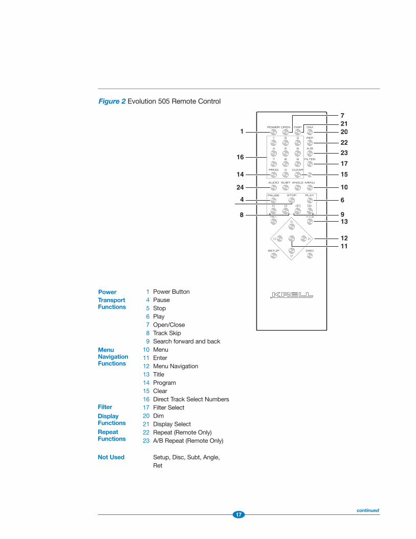
1 Power Button4 Pause 5 Stop6 Play7 Open/Close8 Track Skip 9 Search forward and back
10 Menu11 Enter12 Menu Navigation13 Title14 Program15 Clear 16 Direct Track Select Numbers 17 Filter Select20 Dim21 Display Select22 Repeat (Remote Only)23 A/B Repeat (Remote Only)
Setup, Disc, Subt, Angle,Ret
PowerTransportFunctions
MenuNavigationFunctions
Filter
DisplayFunctionsRepeatFunctions
Not Used
Figure 2 Evolution 505 Remote Control
continued

18
Remote Control DescriptionSee Figure 2 on the previous page
The Evolution 505 remote control provides the same functions as the front panel.In addition, there are three keys that are unique to the remote control, and theseare described below.
22 Repeat KeyReplays selected track until new feature is selected. See also, Using theRepeat Key, on page 27.
23 Repeat A-B KeyCreates a loop between two pre-determined points within a single track orsequential tracks. Press once to select the start of the repeat loop (A), andpress again to select the end of the loop (B). See also, Using the Repeat A/BKey, on page 27.
24 Audio KeyCycles between the stereo and multi-channel layers of an SACD disc.
The following remote control keys are not operational:setup, disc, subt, angle, and ret.
Battery Installation and RemovalThe remote control uses 2 AAA-size 1.5 Volt batteries. Batteries are included withthe shipment. To install the batteries:
1. Remove the remote control backplate, using the supplied T-10 Torx wrench.
2. Install the batteries, following the battery position diagram on the plastic batteryreceptacle.
3. Replace and secure the backplate.
NoteReplace batteries when remote control function becomes intermittent.
Do not use a knife or other sharp object to remove the backplate, as this may damage the
remote control finish.
Remove batteries if the remote control is not used for a long period of time. Battery leakage
can damage the remote control.
(SECTION THREE: Anatomy of the Evolution 505 continued)
19
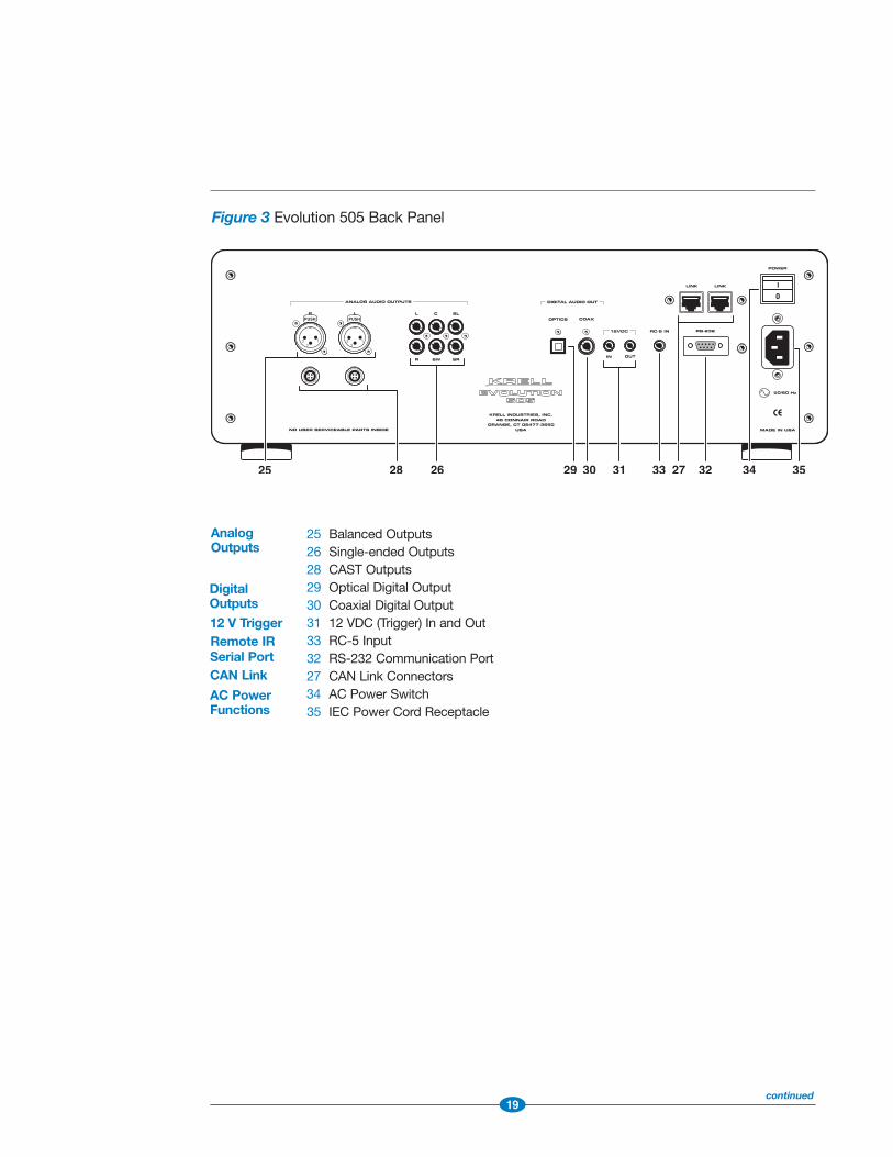
Figure 3 Evolution 505 Back Panel
25 Balanced Outputs26 Single-ended Outputs28 CAST Outputs29 Optical Digital Output 30 Coaxial Digital Output31 12 VDC (Trigger) In and Out33 RC-5 Input32 RS-232 Communication Port 27 CAN Link Connectors 34 AC Power Switch35 IEC Power Cord Receptacle
AnalogOutputs
Remote IRSerial PortCAN Link
AC PowerFunctions
12 V Trigger
DigitalOutputs
continued

20
Back Panel DescriptionSee Figure 3 on the previous page
The back panel provides all the output connections, remote control inputs and out-puts, and the AC power connection. The back panel features are described below.
Analog Audio Outputs 25 Balanced Outputs
One pair of balanced outputs with XLR connectors.
26 Single-ended OutputsFor connection to a multi-channel receiver, with unbalanced RCA connectors:
L, R = left and right channel connections.
C = center channel connection.
SW = subwoofer connection.
SL, SR = left and right surround channel connections.
28 CAST OutputsThe Evolution 505 is equipped with two CAST outputs with 4-pin bayonet con-nectors, for use with Krell CAST-equipped preamplifiers.
Digital Audio Outputs (CD format only)29 Optical Digital Output
One EIAJ fiber optical digital output with a TosLink connector.
30 Coaxial Digital OutputOne S/PDIF coaxial digital output with an RCA connector.
(SECTION THREE: Anatomy of the Evolution 505 continued)

21
Remote Connections on the Back Panel31 12 VDC (Trigger) In and Out
The output sends 12 VDC power on/off signals to other Krell components andother devices that incorporate a 12 V trigger.
The input receives 12 VDC power on/off signals from other components anddevices that incorporate a 12 V trigger.
33 RC-5 InputThe RC-5 remote connector is used with a third party remote control systemthat provides RC-5 (IR) data with the carrier intact, via a wired connection. Astereo tip, ring, sleeve 1/8-inch mini connector is used in the following config-uration: Tip = RC-5 data, Ring = +5 V, Sleeve = GND.
27 CAN LinkThese RJ-45 link connectors are connected in parallel. They are used to con-nect the Evolution 505 in link mode, to other CAN Link-enabled Krell prod-ucts.
32 RS-232 Communication PortThis port allows you to send operational instructions to the Evolution 505using an external computer control system. The RS-232 port uses a 9-pinD-subminiature connector.
Power34 AC Power Switch
Use this switch to change the Evolution 505 from off to stand-by.
35 IEC Power Cord ReceptacleUse the provided IEC standard 15 amp power cord.

22
SECTION FOURConnecting the Evolution 505 to Your SystemUsing Balanced Connections
Krell recommends using balanced interconnect cables. Balanced interconnectcables can not only minimize sonic loss, but are also immune to induced noise,especially with installations using long cables. Balanced connections have 6 dBmore gain than single-ended connections. When level matching is critical, keepthis gain value in mind.
Table 1 Analog and Digital Connections
CD Format Analog Output Digital OutputBalanced Single-ended Optical Coaxial
L + R MULTI
Conventional YES YES NO YES YES
CD
Two-channel YES YES NO NO NO
SACD
Multi-channel YES YES YES NO NO
SACD
23
Connection StepsFollow these steps to connect the Evolution 505 to your system.
1. Make sure all power sources and components are off before connecting inputsand outputs.
2. Neatly organize the wiring between the Evolution 505 and all system compo-nents. Separate AC wires from audio cables to prevent hum or other unwantednoises from being introduced into the system.
3. Remember that balanced outputs use three-pin XLR connectors. Single-endedoutputs use RCA connectors. Maintain the correct left/right orientation of theseoutputs.
4. To play an SACD, you need to use the analog audio outputs. Digital audio out-puts are only available for conventional compact discs.
For multi-channel SACD (SACD MULTI), two-channel SACD (SACD STEREO), andconventional compact disc playback, connect the Evolution 505 multi-channelanalog audio outputs to the surround preamp/processor multi-channel inputs.All multi-channel analog audio outputs are available in the SACD MULTI format.The center (C), subwoofer (SW) and surround (SL, SR) multi-channel outputsare not available in the CD or SACD formats. The left (L) and right (R) multi-channel outputs are always active.
5. For two-channel and conventional compact disc playback only, connect theEvolution 505 balanced analog audio outputs or the left (L) and right (R) multi-channel outputs to the preamplifier balanced or single-ended analog audioinputs.
6. For conventional compact disc playback only, connect the Evolution 505 digitalcoaxial output or digital optics output to the corresponding preamp/processordigital input.
7. Plug the AC power cord into the IEC power connector on the back panel. Thenplug the AC power cord into the wall socket.

24
Evolution 505 Operation This section provides information about operating the Evolution 505. See FrontPanel /Remote Control Description, on pages 13-21, for more Evolution 505 play-back features.
Power OnPress the back panel power switch (34) labeled “1”. When the Evolution 505 is ini-tialized and in the stand-by mode, the red stand-by LED (2) on the front panel illu-minates. Then press the power button (1) on the front panel or the power key onthe remote control, to place the Evolution 505 in the operational mode. When theblue stand-by LED (2) illuminates, the Evolution 505 is in the operational mode andready to play a SACD or a conventional compact disc.
How to Play a Disc1. Press the open/close button (7) or key, to open the disc transport.
2. Place the disc on the transport.
3. Press the open/close button or key again to close the disc transport. The frontpanel display reads the total tracks and time on the disc.
4. Press the play button (6) or key. The format type is seen in the front panel dis-play. The format type disappears, and the front panel display reads TRACK 1 andthe track time as the disc begins playing.
5. Press the stop button (5) or key, and then the title button (13) or key in order toselect another disc format and view available tracks.
6. Adjust the volume level through your system volume control.
7. Press the stop button or key to end disc playback.
8. Press the play button or key to begin playback again, from the first track.
9. To return the Evolution 505 to the stand-by mode, press the power button (1)or key.
SECTION FIVE

25
Using the Title Button or Key (13)Use the title button (13) or key to select one of the three disc formats that theEvolution 505 plays: CD (conventional CD), SACD STEREO (two-channel SACD) andSACD MULTI (multi-channel SACD). The currently selected format is shown in thefront panel display (18). The default format for all SACD discs is SACD MULTI.
The tracks on the selected disc format are the only tracks that can be played. Toaccess tracks on alternate disc format, press the title button or key again. If thereare no tracks in a particular format, that format does not appear in the front paneldisplay.
Perform the following steps in order to access the different formats on ahybrid SACD:
1. Press the stop button (5) or key. The front panel display reads the total tracksand time on the disc.
2. Press the title button (13) or key until the desired format is seen in the frontpanel display. The format name disappears and the front panel display readsthe total tracks and time on the disc. Press the play (6) button or key to beginplaying the selected format.
NoteThe front panel display reads “CHANGING LAYER” whenever you move between the conven-
tional CD and SACD layers.
Navigating a Data DiscThe Evolution 505 is capable of reading MP3 audio files from data discs that youprepare on a personal computer. The front panel display indicates ROOT when youare at the beginning of the disc, F corresponds to a closed folder, and TOP desig-nates an open folder.
Use the following buttons and keys to navigate within a data disc:
1. Press the enter button (11) or key to open a folder or move back to a previousfolder, or to play a track.
2. Press the up and down arrow buttons (12) or keys to move among tracks in afolder.
continued
26
Using the Filter Button or Key (17)Four filters make subtle changes to the high frequencies at ultrasonic levels, alter-ing the sonic presentation from your loudspeakers. Once a filter setting has beenselected, it is held in memory even if the Evolution 505 is turned off and thenreturned to operational status.
Filter 1, 2, 3, and 4 are available in any SACD format. Only Filters 1 and 2 areavailable in the conventional CD format. All filters have a different output gain,higher bandwidth, and a more gradual rolloff in the SACD format, compared toFilter 1 and 2 in the CD format.
Filter 1 and 2 are designed to eliminate aliasing artifacts that are the result of theD/A re-construction process.
Conventional Compact Disc Format FiltersFilter 1 operates flat from 20 Hz to 20 kHz, with a very steep roll-off characteristicabove 20 kHz (21.5 kHz, -3 dB).
Filter 2 operates up to 20 kHz (-3 dB) with a more gradual roll-off characteristicwhen compared to Filter 1.
SACD Format FiltersFilter 1 in the SACD format, has the same relative output gain as Filter 1 and 2 inthe CD format, and it has the highest bandwidth of the four SACD filters. Filters 2,3 and 4 in the SACD format, operate at reduced bandwidth with steeper slope fil-tering and different output gain.
Filter 1 operates up to 180 kHz (highest bandwidth) and has the slowest roll-offcharacteristic with no change in output gain.
Filter 2 operates up to 75 kHz and has the steepest roll-off characteristic. It has a+0.5 dB increase in output gain over the entire audio pass band compared toFilter 1.
Filter 3 operates up to 80 kHz and has the 2nd steepest roll-off characteristic. Ithas a +5.5 dB increase in output gain over the entire audio pass band comparedto Filter 1.
Filter 4 operates up to 90 kHz and has the 3rd steepest roll-off characteristic. Ithas a +3.5 dB increase in output gain over the entire audio pass band comparedto Filter 1.
(SECTION FIVE: Evolution 505 Operation continued)

27
Using the Repeat Key (22)Press the repeat key once to repeat the current track. The front panel display (19)reads REPEAT SINGLE. Press the repeat key twice to repeat the whole disc. The frontpanel display reads REPEAT ALL. Press the repeat key a third time to cancel thisfunction.
Using the Repeat A/B Key (23)To create an A/B loop, start by playing a track. When you hear the part that youwant as the beginning of the loop, press A/B to insert the start position. Press A/Bagain to insert the finish position. A/B playback will automatically begin and willcontinue indefinitely. To delete, press A/B again, or press the stop button (5) or key.
Using the Front Panel Display (19)The front panel display shows the disc type, the elapsed time of the track, and thefeature that has been selected, for example: REPEAT ALL or REPEAT SINGLE. Press thedisplay button (21) or key to show track time remaining, disc elapsed time, or disctime remaining. Press the dim button (20) or key to reduce the brightness of thedisplay.
Using the 12 V Trigger (31)This function allows you to turn other components on or off, or to and from stand-by, from the Evolution 505. When the Evolution 505 is switched between stand-byand the operational mode, the 12 V trigger sends a signal from the 12 VDC Outthat will switch other components, allowing whole systems or parts of systems tobe easily coordinated.
The 12 VDC input allows you to turn the Evolution 505 on or off, or to and fromstand-by, from other components.
NoteWhen the component is in the operational mode, the 12 VDC Out provides 12 V of DC out-
put. When the component is in the stand-by mode or off, the DC output is 0 V. The 12 VDC
output current is limited to 30 mA. Consult the owner’s reference of the components used
in a custom installation to take full advantage of the remote capability of the Evolution 505.
Using the RS-232 Port (32)For more information on using the RS-232 communications port, see RS-232 Port:Sending Commands and Interpreting Data, the developer’s reference for theEvolution 505.

28
WarrantyKrell products have a limited warranty. Amplifiers, preamplifiers, preamp/processors,and receivers carry a limited warranty of five years for parts and labor on circuitry.Loudspeakers carry a limited warranty of five years for parts and labor. CD andDVD players carry a limited warranty of five years for parts and labor on circuitry,and three years for parts and labor on mechanical parts.
Should the product fail to perform at any time during the warranty, Krell will repair itat no cost to the owner, except as set forth in this warranty.
This warranty does not apply to damage caused by acts of God or nature.
This warranty shall be in lieu of any other warranty, expressed or implied, including,but not limited to, any implied warranty of merchantability or fitness for a particularpurpose. There are no warranties which exceed beyond those described in thisdocument, if the product does not perform as warranted herein, the owner’s soleremedy shall be repair. In no event will Krell be liable for incidental or consequentialdamages arising from purchase, use, or inability to use the product, even if Krellhas been advised of the possibility of such damages.
Proof of purchase in the form of a bill of sale or receipted invoice substantiatingthat the product is within the warranty period must be presented to obtain warrantyservice. The warranty begins on the date of the original retail purchase, as noted onthe bill of sale or receipted invoice from an authorized Krell dealer or distributor.Previously owned equipment, when re-purchased from an authorized Krell dealer ordistributor, has the balance of the original warranty, based on the original date ofmanufacture.
The warranty for a Krell product is valid only in the country to which it was originallyshipped, through the authorized Krell distributor for that country, and at the factory.There may be restrictions on or changes to Krell’s warranty because of regulationswithin a specific country. Please check with your distributor for a complete under-standing of the warranty in your country.
If the product is serviced by a distributor who did not import the unit, there may bea charge for service, even if the product is within the warranty period.
Freight to the factory is your responsibility. Return freight within the United States(U.S.A.) is included in the warranty. If you have purchased your Krell product out-side the U.S.A. and wish to have it serviced at the factory, all freight and associatedcharges to the factory are your responsibility. Krell will pay return freight to theU.S.A.-based freight forwarder of your choice. Freight and other charges to ship theproduct from the freight forwarder to you are also your responsibility.

29
Krell is not responsible for any damage incurred in transit. Krell will file claims fordamages as necessary for a product damaged in transit to the factory. You areresponsible for filing claims for shipping damages during the return shipment.
Krell does not supply replacement parts and/or products to the owner of the prod-uct. Replacement parts and/or products will be furnished only to the distributorperforming service on this product on an exchange basis only; any parts and/orproducts returned to Krell for exchange become the property of Krell.
No expressed or implied warranty is made for any Krell product damaged by acci-dent, abuse, misuse, natural or personal disaster, or unauthorized modification.
Any unauthorized voltage conversion, disassembly, component replacement,perforation of chassis, updates, or modifications performed to the productwill void the warranty.
The operating voltage of the product is determined by the factory and can only bechanged by an authorized Krell distributor or at the factory. The voltage for thisproduct in the U.S.A. cannot be changed until six months from the original pur-chase date.
In the event that Krell receives a product for warranty service that has been modi-fied in any way without Krell authorization, all warranties on that product will bevoid. The product will be returned to original factory layout specifications at theowner’s expense before it is repaired. All repairs required after the product hasbeen returned to original factory specifications will be charged to the customer, atcurrent parts and labor rates.
All operational features, functions, and specifications and policies are subject tochange without notification.
To register your product for warranty benefits, please complete and return theWarranty Registration Card enclosed in the shipping box within 15 days of pur-chase. Thank you.

30
Return Authorization ProcedureIf you believe there is a problem with your component, please contact your dealer,distributor, or the Krell factory to discuss the problem before you return the com-ponent for repair. To expedite service, you may wish to complete and e-mail theService Request Form in the Service Section of our website at:
http://www.krellonline.com
To return a product to Krell, please follow this procedure so that we mayserve you better.
1. Obtain a Return Authorization Number (R/A number) and shipping address from the Krell Service Department.
2. Insure and accept all liability for loss or damage to the product during shipment to the Krell factory and ensure all freight (shipping) charges are prepaid.
The product may also be hand delivered if arrangements with the ServiceDepartment have been made in advance. Proof of purchase will be required forwarranty validation at the time of hand delivery.
IMPORTANTUse the original packaging to ensure the safe transit of the product to the factory,dealer, or distributor. Krell may, at its discretion, return a product in new packagingand bill the owner for such packaging if the product received by Krell was boxed innonstandard packaging or if the original packaging was so damaged that it wasunusable. If Krell determines that new packaging is required, the owner will be noti-fied before the product is returned.
To purchase additional packaging, please contact your authorized Krell dealer, distributor, or the Krell Service Department for assistance.
To contact the Krell Service Department
TEL 203-298-4020, Monday-Friday9:00 AM to 5:00 PM EST
FAX 203-795-2287E-MAIL [email protected] http://www.krellonline.com
Evolution 505 PRODUCT MODEL NUMBER SERIAL NUMBER

31
Frequency response20 Hz to 20 kHz +0.0, -0.5 dB
Signal to noise ratio“A” weighted 105 dB
THD20 Hz to 20 kHz, -82 dB
Power Consumption61 W
Analog Audio outputs1 pr. CAST via 4-pin bayonet connectors1 pr. balanced via XLR connector6 single-ended via RCA connector
Digital Audio outputs1 S/PDIF via RCA, 1 EIAJ optical via TosLink
Remote Control1 Wireless IR Remote1 Remote IR sensor input via
a 3-conductor 3.5 mm connector
Control inputs1 RS-232 port via a 9-pin D-subminiature connector1 12 VDC trigger input via 3.5 mm connector1 Krell CAN Link via an RJ-45 connector
Control outputs1 12 VDC trigger output via 3.5 mm connectors1 Krell CAN Link via an RJ-45 connector
Dimensions17.3 in. W x 6 in. H x 17.3 in. D43.8 cm W x 15.3 cm H x 43.8 cm D
WeightShipped: 37 lbs., 16.8 kg Unit only: 29 lbs., 13.2 kg
NoteAll operational features, functions, specifications, and policies
are subject to change with out notification.
Specifications

OWNER’S REFERENCE
V06.0
KRELL INDUSTRIES, INC.
45 CONNAIR ROAD
ORANGE, CT 06477-3650 USA
TEL: 203-298-4000 • FAX: 203-891-2028
E-MAIL: sa les@kre l lon l ine.com
http: / /www.kre l lon l ine.com
E V O L U T I O N 5 0 5
S A C D / C D P L AY E R