evolutions in 802.11 design - cwnp.com · 800 ns gi 400 ns gi 800 ns gi 400 ns gi 800 ns gi 400 ns...
TRANSCRIPT
IT Professional Wi-Fi Trek 2015
#wifitrek
Evolutions in 802.11 DesignHigh-Density, Capacity Planning and Survey Methodologies
Christian J. EstesCCIE Wireless #42615
CWNE #85
#wifitrek
Introduction
Solutions Architect for Dimension Data; Consulting Systems Engineer for Wireless Practice
6 years at Cisco in Wireless Networking Business Unit on the Wireless Escalation team
Duke University, Bank of America, Target, Apple, NYSE, and Stanford University
Authored the Voice over Wireless LAN Troubleshooting located on CCO
Technical Editor for the Cisco Press book entitled, "Designing and Deploying 802.11n Wireless
Networks - First Edition" along with Tom Carpenter and authored by Jim Geier.
B.S. in Computer Engineering and M.S. Degree in Information Assurance
CWNE #85, CCIE Wireless #42615
#wifitrek
Agenda
High Density Use Cases
802.11n vs. 802.11ac
SU-MIMO vs. MU-MIMO
MU-MIMO, TxBF and Antenna Selection
Spectrum Use / Reuse
Capacity Planning
Customer Scenario
Calculating Total System Throughput (TST)
Per Device Throughput (PDT)
General Capacity Planning
Wireless LAN Best Practices for High Density
#wifitrek
High-Density Use Cases
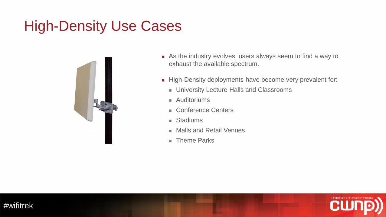
As the industry evolves, users always seem to find a way to
exhaust the available spectrum.
High-Density deployments have become very prevalent for:
University Lecture Halls and Classrooms
Auditoriums
Conference Centers
Stadiums
Malls and Retail Venues
Theme Parks
#wifitrek
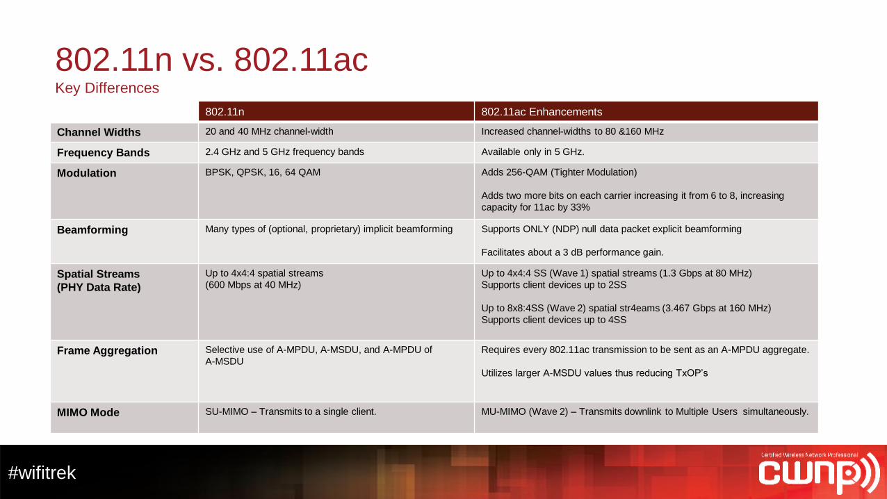
802.11n vs. 802.11acKey Differences
802.11n 802.11ac Enhancements
Channel Widths 20 and 40 MHz channel-width Increased channel-widths to 80 &160 MHz
Frequency Bands 2.4 GHz and 5 GHz frequency bands Available only in 5 GHz.
Modulation BPSK, QPSK, 16, 64 QAM Adds 256-QAM (Tighter Modulation)
Adds two more bits on each carrier increasing it from 6 to 8, increasing
capacity for 11ac by 33%
Beamforming Many types of (optional, proprietary) implicit beamforming Supports ONLY (NDP) null data packet explicit beamforming
Facilitates about a 3 dB performance gain.
Spatial Streams
(PHY Data Rate)
Up to 4x4:4 spatial streams
(600 Mbps at 40 MHz)
Up to 4x4:4 SS (Wave 1) spatial streams (1.3 Gbps at 80 MHz)
Supports client devices up to 2SS
Up to 8x8:4SS (Wave 2) spatial str4eams (3.467 Gbps at 160 MHz)
Supports client devices up to 4SS
Frame Aggregation Selective use of A-MPDU, A-MSDU, and A-MPDU of
A-MSDU
Requires every 802.11ac transmission to be sent as an A-MPDU aggregate.
Utilizes larger A-MSDU values thus reducing TxOP’s
MIMO Mode SU-MIMO – Transmits to a single client. MU-MIMO (Wave 2) – Transmits downlink to Multiple Users simultaneously.
#wifitrek
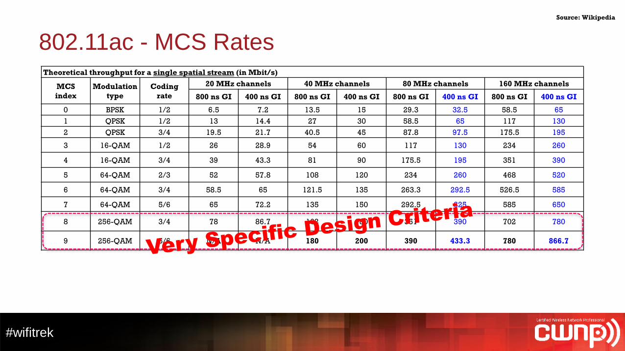
802.11ac - MCS RatesTheoretical throughput for a single spatial stream (in Mbit/s)
MCS
index
Modulation
type
Coding
rate
20 MHz channels 40 MHz channels 80 MHz channels 160 MHz channels
800 ns GI 400 ns GI 800 ns GI 400 ns GI 800 ns GI 400 ns GI 800 ns GI 400 ns GI
0 BPSK 1/2 6.5 7.2 13.5 15 29.3 32.5 58.5 65
1 QPSK 1/2 13 14.4 27 30 58.5 65 117 130
2 QPSK 3/4 19.5 21.7 40.5 45 87.8 97.5 175.5 195
3 16-QAM 1/2 26 28.9 54 60 117 130 234 260
4 16-QAM 3/4 39 43.3 81 90 175.5 195 351 390
5 64-QAM 2/3 52 57.8 108 120 234 260 468 520
6 64-QAM 3/4 58.5 65 121.5 135 263.3 292.5 526.5 585
7 64-QAM 5/6 65 72.2 135 150 292.5 325 585 650
8 256-QAM 3/4 78 86.7 162 180 351 390 702 780
9 256-QAM 5/6 N/A N/A 180 200 390 433.3 780 866.7
Source: Wikipedia
IT Professional Wi-Fi Trek 2015
#wifitrek
MIMO and Antenna Selection
#wifitrek
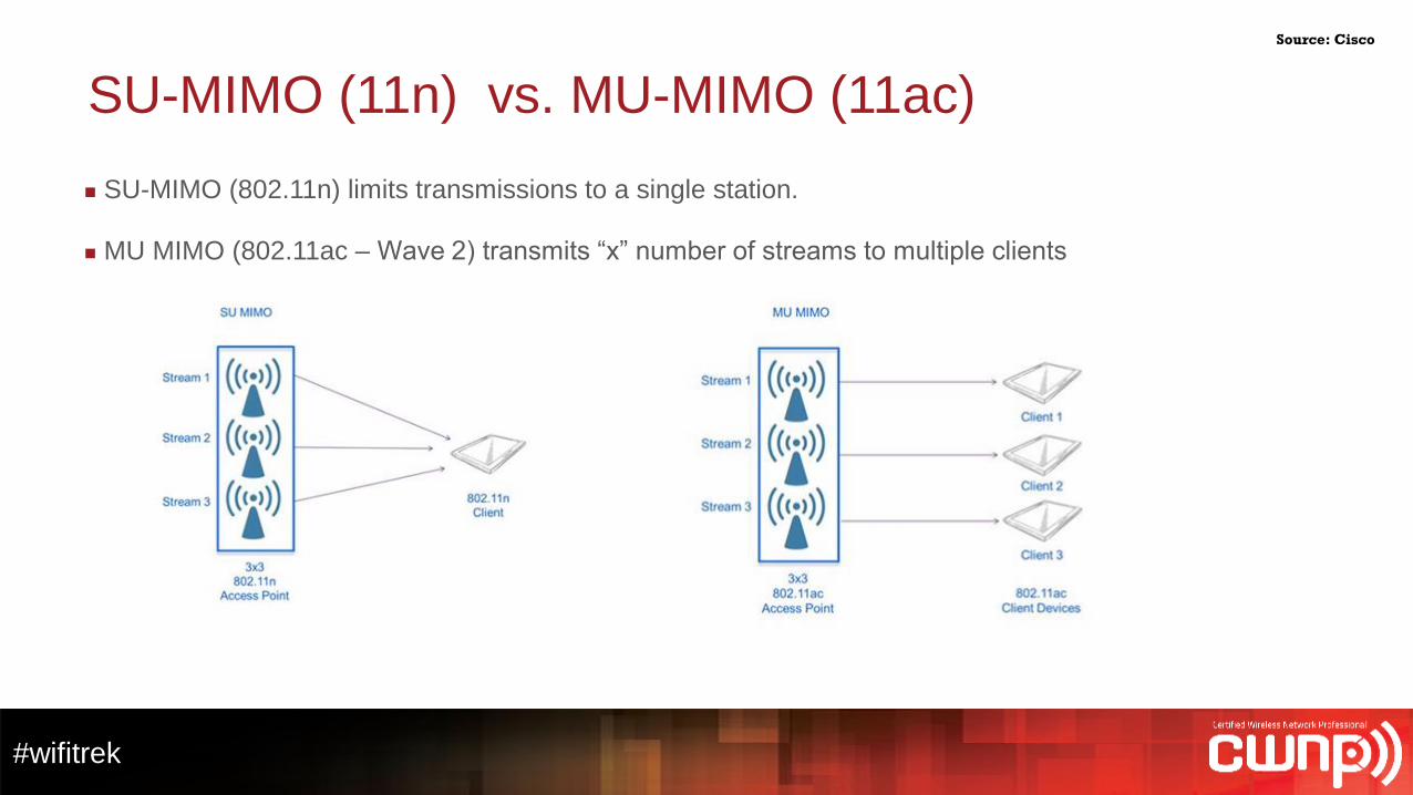
SU-MIMO (11n) vs. MU-MIMO (11ac)
SU-MIMO (802.11n) limits transmissions to a single station.
MU MIMO (802.11ac – Wave 2) transmits “x” number of streams to multiple clients
Source: Cisco
#wifitrek
MU-MIMO – Multi-User MIMONDP (explicit) TxBF Beamforming
Source: Cisco
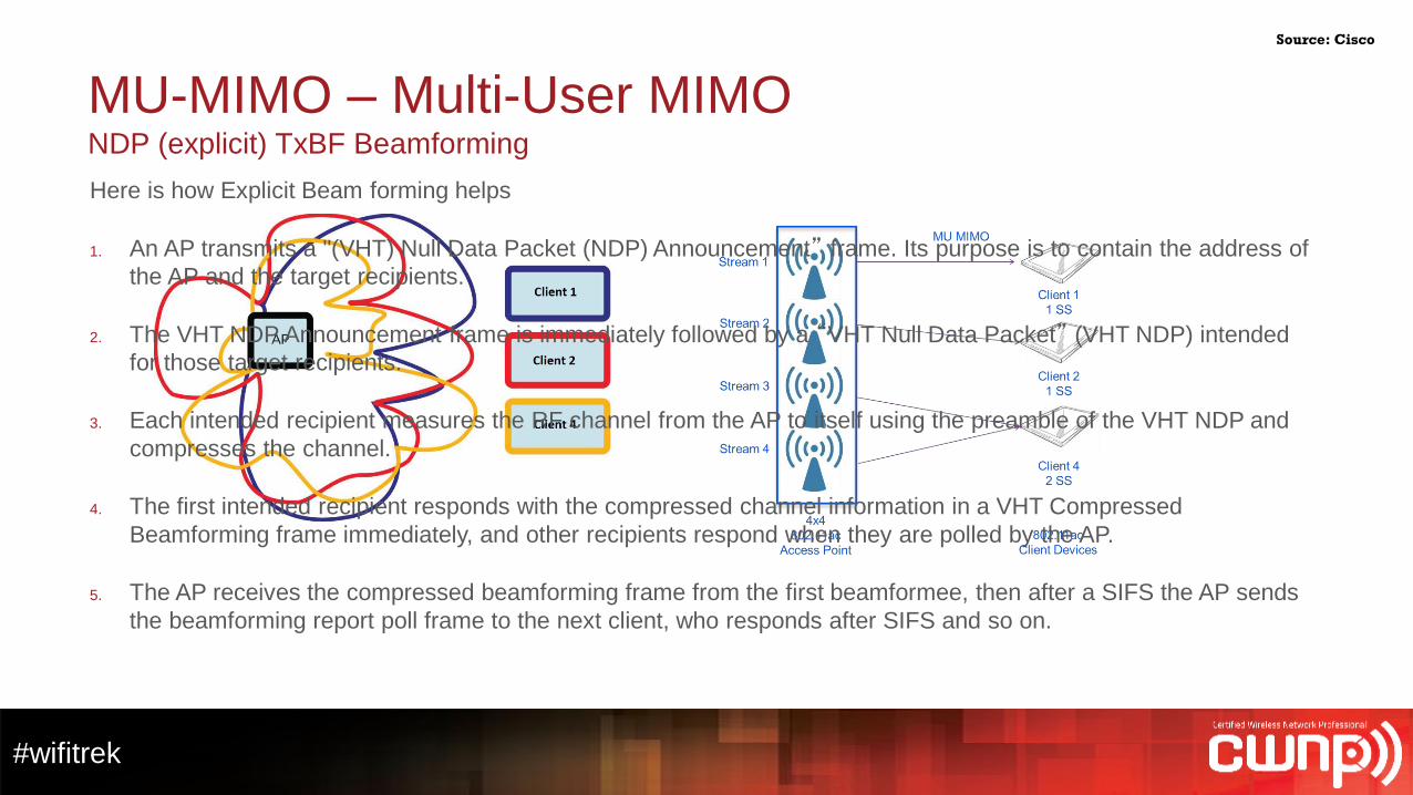
Here is how Explicit Beam forming helps
1. An AP transmits a "(VHT) Null Data Packet (NDP) Announcement” frame. Its purpose is to contain the address of
the AP and the target recipients.
2. The VHT NDP Announcement frame is immediately followed by a “VHT Null Data Packet” (VHT NDP) intended
for those target recipients.
3. Each intended recipient measures the RF channel from the AP to itself using the preamble of the VHT NDP and
compresses the channel.
4. The first intended recipient responds with the compressed channel information in a VHT Compressed
Beamforming frame immediately, and other recipients respond when they are polled by the AP.
5. The AP receives the compressed beamforming frame from the first beamformee, then after a SIFS the AP sends
the beamforming report poll frame to the next client, who responds after SIFS and so on.
#wifitrek
Patch, Panel or Sector AntennasAntenna Selection
Source: Terrawave
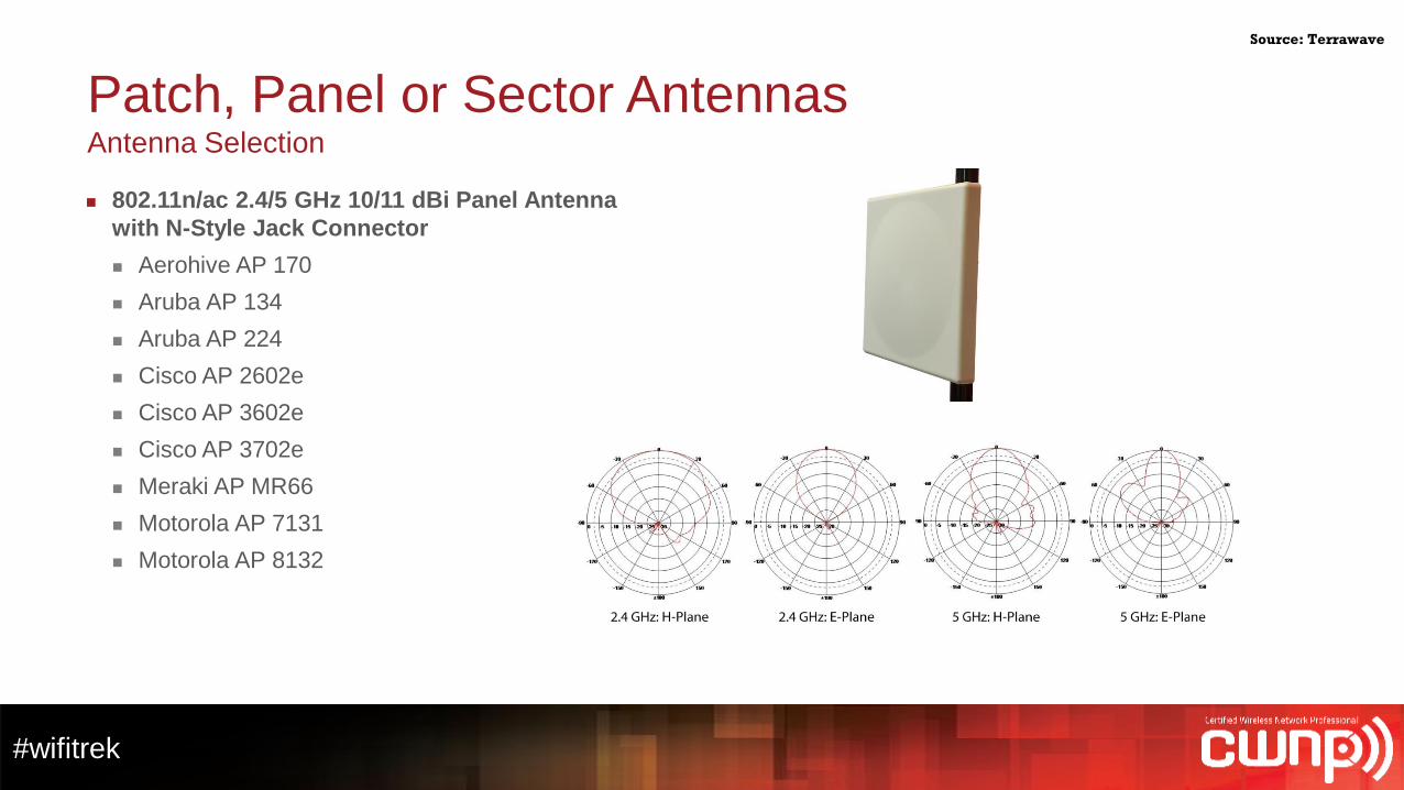
802.11n/ac 2.4/5 GHz 10/11 dBi Panel Antenna
with N-Style Jack Connector
Aerohive AP 170
Aruba AP 134
Aruba AP 224
Cisco AP 2602e
Cisco AP 3602e
Cisco AP 3702e
Meraki AP MR66
Motorola AP 7131
Motorola AP 8132
#wifitrek
Indoor Patch AntennasCisco Live
Source: Terrawave and Cisco Live
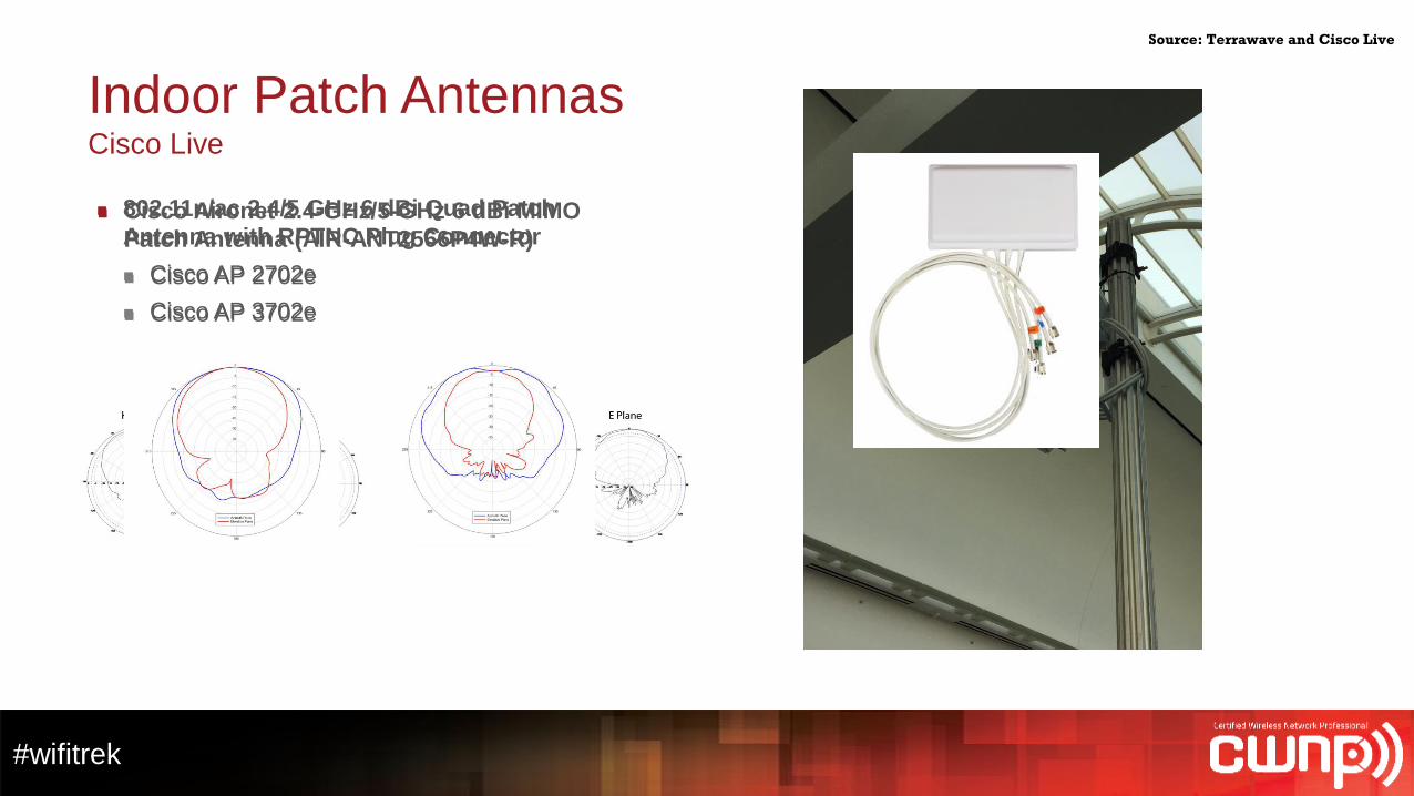
Cisco Aironet 2.4-GHz/5-GHz 6 dBi MIMO
Patch Antenna (AIR-ANT2566P4W-R)
Cisco AP 2702e
Cisco AP 3702e
802.11n/ac 2.4/5 GHz 6 dBi Quad Patch
Antenna with RPTNC Plug Connector
Cisco AP 2702e
Cisco AP 3702e
#wifitrek
Directional Antennas and DowntiltInner and Outer Cell Radius
Source: Cisco
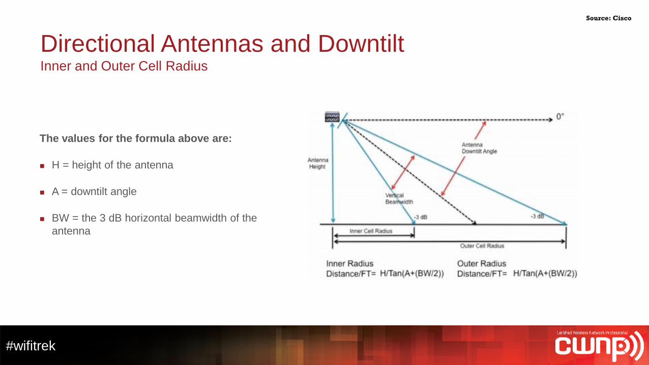
The values for the formula above are:
H = height of the antenna
A = downtilt angle
BW = the 3 dB horizontal beamwidth of the
antenna
#wifitrek
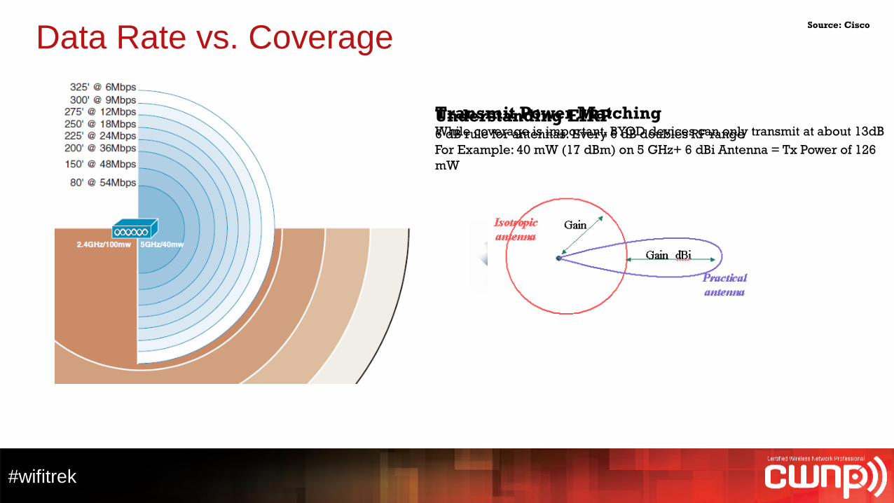
Understanding EIRP6 dB rule for antennas. Every 6 dB doubles RF range
For Example: 40 mW (17 dBm) on 5 GHz+ 6 dBi Antenna = Tx Power of 126
mW
Data Rate vs. Coverage
Transmit Power MatchingWhile coverage is important, BYOD devices can only transmit at about 13dB
Source: Cisco
#wifitrek
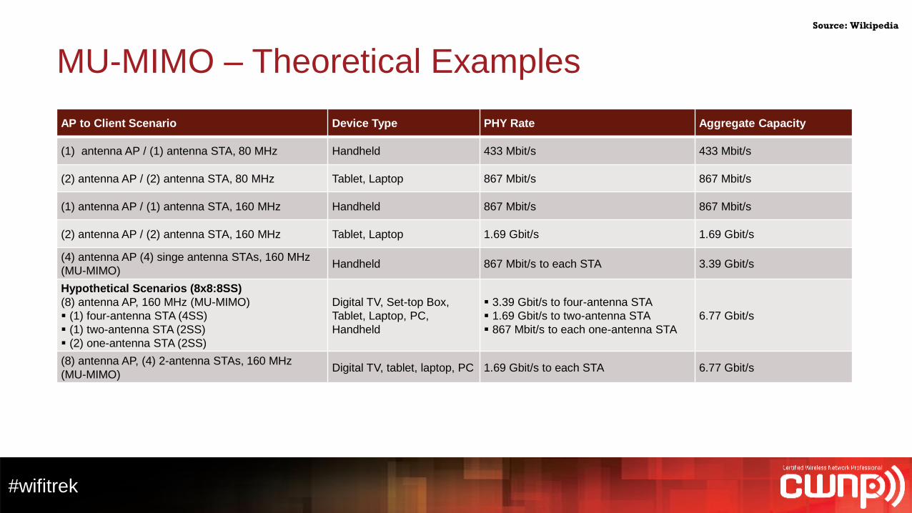
MU-MIMO – Theoretical Examples
AP to Client Scenario Device Type PHY Rate Aggregate Capacity
(1) antenna AP / (1) antenna STA, 80 MHz Handheld 433 Mbit/s 433 Mbit/s
(2) antenna AP / (2) antenna STA, 80 MHz Tablet, Laptop 867 Mbit/s 867 Mbit/s
(1) antenna AP / (1) antenna STA, 160 MHz Handheld 867 Mbit/s 867 Mbit/s
(2) antenna AP / (2) antenna STA, 160 MHz Tablet, Laptop 1.69 Gbit/s 1.69 Gbit/s
(4) antenna AP (4) singe antenna STAs, 160 MHz
(MU-MIMO)Handheld 867 Mbit/s to each STA 3.39 Gbit/s
Hypothetical Scenarios (8x8:8SS)
(8) antenna AP, 160 MHz (MU-MIMO)
(1) four-antenna STA (4SS)
(1) two-antenna STA (2SS)
(2) one-antenna STA (2SS)
Digital TV, Set-top Box,
Tablet, Laptop, PC,
Handheld
3.39 Gbit/s to four-antenna STA
1.69 Gbit/s to two-antenna STA
867 Mbit/s to each one-antenna STA
6.77 Gbit/s
(8) antenna AP, (4) 2-antenna STAs, 160 MHz
(MU-MIMO)Digital TV, tablet, laptop, PC 1.69 Gbit/s to each STA 6.77 Gbit/s
Source: Wikipedia
IT Professional Wi-Fi Trek 2015
#wifitrek
Spectrum Use/Reuse
#wifitrek
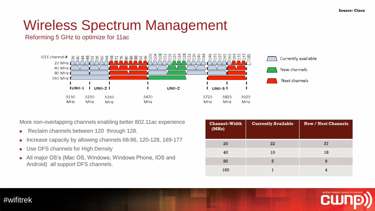
Wireless Spectrum Management Reforming 5 GHz to optimize for 11ac
More non-overlapping channels enabling better 802.11ac experience
Reclaim channels between 120 through 128.
Increase capacity by allowing channels 68-96, 120-128, 169-177
Use DFS channels for High Density
All major OS’s (Mac OS, Windows, Windows Phone, IOS and
Android) all support DFS channels.
Channel–Width
(MHz)
Currently Available New / Next Channels
20 22 37
40 10 18
80 5 9
160 1 4
Source: Cisco
#wifitrek
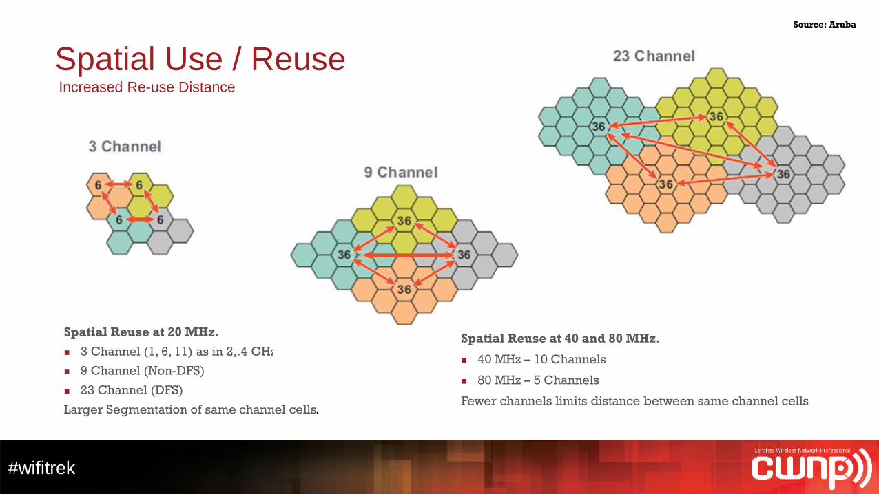
Spatial Use / ReuseIncreased Re-use Distance
Source: Aruba
Spatial Reuse at 20 MHz.
3 Channel (1, 6, 11) as in 2,.4 GHz
9 Channel (Non-DFS)
23 Channel (DFS)
Larger Segmentation of same channel cells.
Spatial Reuse at 40 and 80 MHz.
40 MHz – 10 Channels
80 MHz – 5 Channels
Fewer channels limits distance between same channel cells
#wifitrek
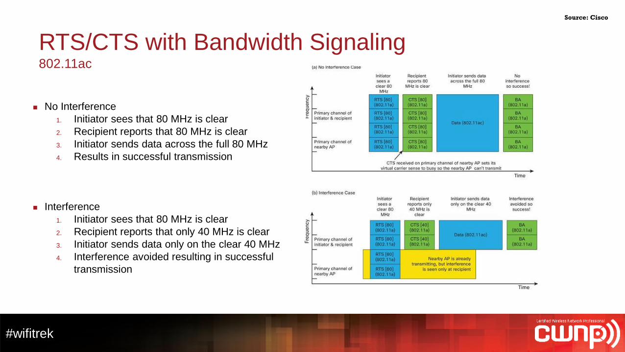
RTS/CTS with Bandwidth Signaling802.11ac
No Interference
1. Initiator sees that 80 MHz is clear
2. Recipient reports that 80 MHz is clear
3. Initiator sends data across the full 80 MHz
4. Results in successful transmission
Interference
1. Initiator sees that 80 MHz is clear
2. Recipient reports that only 40 MHz is clear
3. Initiator sends data only on the clear 40 MHz
4. Interference avoided resulting in successful
transmission
Source: Cisco
IT Professional Wi-Fi Trek 2015
#wifitrek
Customer Scenario
#wifitrek
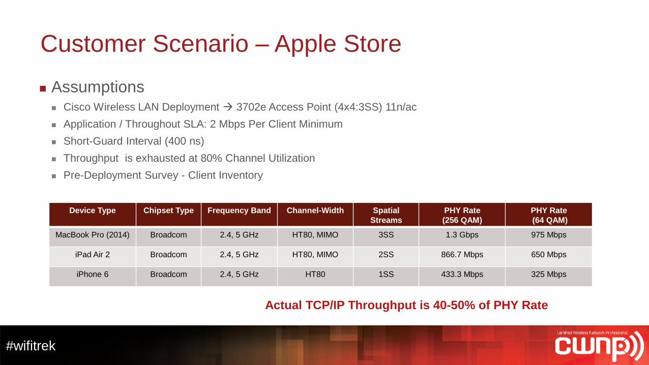
Customer Scenario – Apple Store
Assumptions Cisco Wireless LAN Deployment 3702e Access Point (4x4:3SS) 11n/ac
Application / Throughout SLA: 2 Mbps Per Client Minimum
Short-Guard Interval (400 ns)
Throughput is exhausted at 80% Channel Utilization
Pre-Deployment Survey - Client Inventory
Device Type Chipset Type Frequency Band Channel-Width Spatial
Streams
PHY Rate
(256 QAM)
PHY Rate
(64 QAM)
MacBook Pro (2014) Broadcom 2.4, 5 GHz HT80, MIMO 3SS 1.3 Gbps 975 Mbps
iPad Air 2 Broadcom 2.4, 5 GHz HT80, MIMO 2SS 866.7 Mbps 650 Mbps
iPhone 6 Broadcom 2.4, 5 GHz HT80 1SS 433.3 Mbps 325 Mbps
Actual TCP/IP Throughput is 40-50% of PHY Rate
#wifitrek
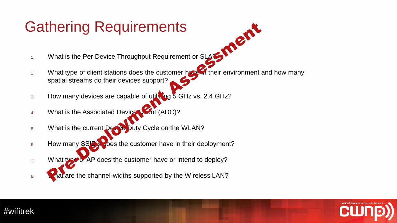
Gathering Requirements
1. What is the Per Device Throughput Requirement or SLA?
2. What type of client stations does the customer have in their environment and how many
spatial streams do their devices support?
3. How many devices are capable of utilizing 5 GHz vs. 2.4 GHz?
4. What is the Associated Device Count (ADC)?
5. What is the current Device Duty Cycle on the WLAN?
6. How many SSID’s does the customer have in their deployment?
7. What type of AP does the customer have or intend to deploy?
8. What are the channel-widths supported by the Wireless LAN?
#wifitrek
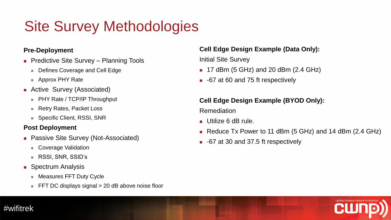
Site Survey Methodologies
Pre-Deployment
Predictive Site Survey – Planning Tools
Defines Coverage and Cell Edge
Approx PHY Rate
Active Survey (Associated)
PHY Rate / TCP/IP Throughput
Retry Rates, Packet Loss
Specific Client, RSSI, SNR
Post Deployment
Passive Site Survey (Not-Associated)
Coverage Validation
RSSI, SNR, SSID’s
Spectrum Analysis
Measures FFT Duty Cycle
FFT DC displays signal > 20 dB above noise floor
Cell Edge Design Example (Data Only):
Initial Site Survey
17 dBm (5 GHz) and 20 dBm (2.4 GHz)
-67 at 60 and 75 ft respectively
Cell Edge Design Example (BYOD Only):
Remediation
Utilize 6 dB rule.
Reduce Tx Power to 11 dBm (5 GHz) and 14 dBm (2.4 GHz)
-67 at 30 and 37.5 ft respectively
IT Professional Wi-Fi Trek 2015
#wifitrek
Capacity Planning…a practical approach to High Density
#wifitrek
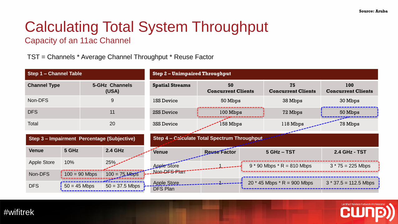
Calculating Total System ThroughputCapacity of an 11ac Channel
Step 1 – Channel Table
Channel Type 5-GHz Channels
(USA)
Non-DFS 9
DFS 11
Total 20
Step 2 – Unimpaired Throughput
Spatial Streams 50
Concurrent Clients
75
Concurrent Clients
100
Concurrent Clients
1SS Device 50 Mbps 38 Mbps 30 Mbps
2SS Device 100 Mbps 72 Mbps 50 Mbps
3SS Device 158 Mbps 118 Mbps 78 Mbps
Step 3 – Impairment Percentage (Subjective)
Venue 5 GHz 2.4 GHz
Apple Store 10% 25%
Non-DFS 100 = 90 Mbps 100 = 75 Mbps
DFS 50 = 45 Mbps 50 = 37.5 Mbps
Step 4 – Calculate Total Spectrum Throughput
Venue Reuse Factor 5 GHz – TST 2.4 GHz - TST
Apple Store
Non-DFS Plan
1 9 * 90 Mbps * R = 810 Mbps 3 * 75 = 225 Mbps
Apple Store
DFS Plan
1 20 * 45 Mbps * R = 900 Mbps 3 * 37.5 = 112.5 Mbps
TST = Channels * Average Channel Throughput * Reuse Factor
Source: Aruba
#wifitrek
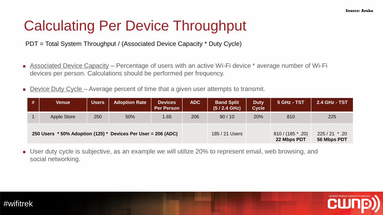
Calculating Per Device ThroughputPDT = Total System Throughput / (Associated Device Capacity * Duty Cycle)
Associated Device Capacity – Percentage of users with an active Wi-Fi device * average number of Wi-Fi
devices per person. Calculations should be performed per frequency.
Device Duty Cycle – Average percent of time that a given user attempts to transmit.
User duty cycle is subjective, as an example we will utilize 20% to represent email, web browsing, and
social networking.
# Venue Users Adoption Rate Devices
Per Person
ADC Band Split
(5 / 2.4 GHz)
Duty
Cycle
5 GHz - TST 2.4 GHz - TST
1 Apple Store 250 50% 1.65 206 90 / 10 20% 810 225
250 Users * 50% Adoption (125) * Devices Per User = 206 (ADC) 185 / 21 Users 810 / (185 * .20)
22 Mbps PDT
225 / 21 * .20
56 Mbps PDT
Source: Aruba
#wifitrek
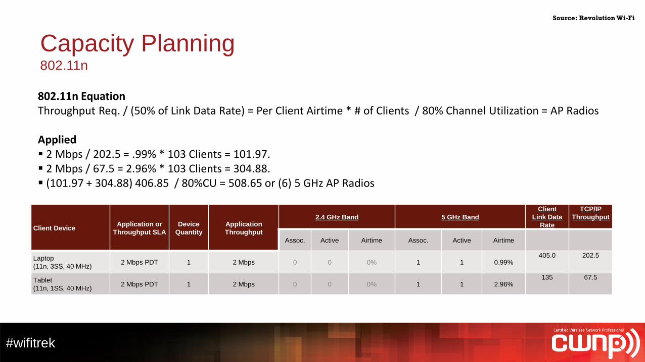
Capacity Planning802.11n
Client DeviceApplication or
Throughput SLA
Device
Quantity
Application
Throughput
2.4 GHz Band 5 GHz Band
Client
Link Data
Rate
TCP/IP
Throughput
Assoc. Active Airtime Assoc. Active Airtime
Laptop
(11n, 3SS, 40 MHz)2 Mbps PDT 1 2 Mbps 0 0 0% 1 1 0.99%
405.0 202.5
Tablet
(11n, 1SS, 40 MHz)2 Mbps PDT 1 2 Mbps 0 0 0% 1 1 2.96%
135 67.5
802.11n EquationThroughput Req. / (50% of Link Data Rate) = Per Client Airtime * # of Clients / 80% Channel Utilization = AP Radios
Applied 2 Mbps / 202.5 = .99% * 103 Clients = 101.97. 2 Mbps / 67.5 = 2.96% * 103 Clients = 304.88. (101.97 + 304.88) 406.85 / 80%CU = 508.65 or (6) 5 GHz AP Radios
Source: Revolution Wi-Fi
#wifitrek
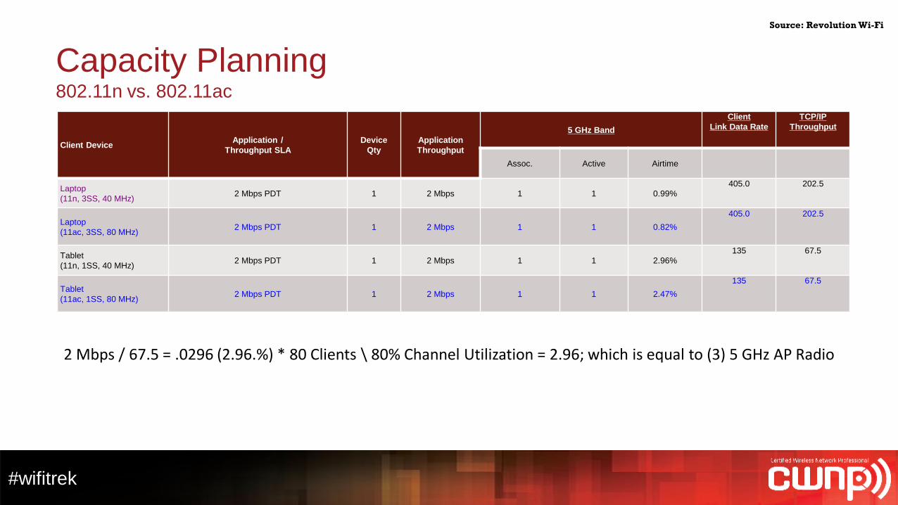
Capacity Planning802.11n vs. 802.11ac
Client DeviceApplication /
Throughput SLA
Device
Qty
Application
Throughput
5 GHz Band
Client
Link Data Rate
TCP/IP
Throughput
Assoc. Active Airtime
Laptop
(11n, 3SS, 40 MHz)2 Mbps PDT 1 2 Mbps 1 1 0.99%
405.0 202.5
Laptop
(11ac, 3SS, 80 MHz)2 Mbps PDT 1 2 Mbps 1 1 0.82%
405.0 202.5
Tablet
(11n, 1SS, 40 MHz)2 Mbps PDT 1 2 Mbps 1 1 2.96%
135 67.5
Tablet
(11ac, 1SS, 80 MHz)2 Mbps PDT 1 2 Mbps 1 1 2.47%
135 67.5
2 Mbps / 67.5 = .0296 (2.96.%) * 80 Clients \ 80% Channel Utilization = 2.96; which is equal to (3) 5 GHz AP Radio
Source: Revolution Wi-Fi
#wifitrek
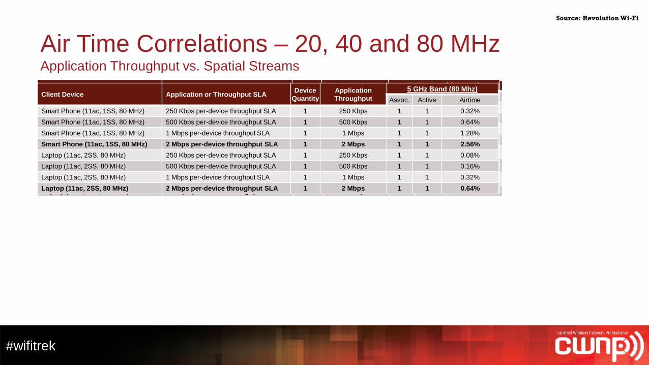
Air Time Correlations – 20, 40 and 80 MHzApplication Throughput vs. Spatial Streams
Client Device Application or Throughput SLADevice
Quantity
Application
Throughput
5 GHz Band (20 MHz)
Assoc. Active Airtime
Smart Phone (11ac, 1SS, 80 MHz) 250 Kbps per-device throughput SLA 1 250 Kbps 1 1 0.72%
Smart Phone (11ac, 1SS, 80 MHz) 500 Kbps per-device throughput SLA 1 500 Kbps 1 1 1.44%
Smart Phone (11ac, 1SS, 80 MHz) 1 Mbps per-device throughput SLA 1 1 Mbps 1 1 2.88%
Smart Phone (11ac, 1SS, 80 MHz) 2 Mbps per-device throughput SLA 1 2 Mbps 1 1 5.77%
Laptop (11ac, 2SS, 80 MHz) 250 Kbps per-device throughput SLA 1 250 Kbps 1 1 0.29%
Laptop (11ac, 2SS, 80 MHz) 500 Kbps per-device throughput SLA 1 500 Kbps 1 1 0.58%
Laptop (11ac, 2SS, 80 MHz) 1 Mbps per-device throughput SLA 1 1 Mbps 1 1 1.15%
Laptop (11ac, 2SS, 80 MHz) 2 Mbps per-device throughput SLA 1 2 Mbps 1 1 2.31%
Source: Revolution Wi-Fi
Client Device Application or Throughput SLADevice
Quantity
Application
Throughput
5 GHz Band (40 MHz)
Assoc. Active Airtime
Smart Phone (11ac, 1SS, 80 MHz) 250 Kbps per-device throughput SLA 1 250 Kbps 1 1 0.46%
Smart Phone (11ac, 1SS, 80 MHz) 500 Kbps per-device throughput SLA 1 500 Kbps 1 1 0.93%
Smart Phone (11ac, 1SS, 80 MHz) 1 Mbps per-device throughput SLA 1 1 Mbps 1 1 1.85%
Smart Phone (11ac, 1SS, 80 MHz) 2 Mbps per-device throughput SLA 1 2 Mbps 1 1 3.7%
Laptop (11ac, 2SS, 80 MHz) 250 Kbps per-device throughput SLA 1 250 Kbps 1 1 0.15%
Laptop (11ac, 2SS, 80 MHz) 500 Kbps per-device throughput SLA 1 500 Kbps 1 1 0.31%
Laptop (11ac, 2SS, 80 MHz) 1 Mbps per-device throughput SLA 1 1 Mbps 1 1 0.62%
Laptop (11ac, 2SS, 80 MHz) 2 Mbps per-device throughput SLA 1 2 Mbps 1 1 1.23%
Client Device Application or Throughput SLADevice
Quantity
Application
Throughput
5 GHz Band (80 Mhz)
Assoc. Active Airtime
Smart Phone (11ac, 1SS, 80 MHz) 250 Kbps per-device throughput SLA 1 250 Kbps 1 1 0.32%
Smart Phone (11ac, 1SS, 80 MHz) 500 Kbps per-device throughput SLA 1 500 Kbps 1 1 0.64%
Smart Phone (11ac, 1SS, 80 MHz) 1 Mbps per-device throughput SLA 1 1 Mbps 1 1 1.28%
Smart Phone (11ac, 1SS, 80 MHz) 2 Mbps per-device throughput SLA 1 2 Mbps 1 1 2.56%
Laptop (11ac, 2SS, 80 MHz) 250 Kbps per-device throughput SLA 1 250 Kbps 1 1 0.08%
Laptop (11ac, 2SS, 80 MHz) 500 Kbps per-device throughput SLA 1 500 Kbps 1 1 0.16%
Laptop (11ac, 2SS, 80 MHz) 1 Mbps per-device throughput SLA 1 1 Mbps 1 1 0.32%
Laptop (11ac, 2SS, 80 MHz) 2 Mbps per-device throughput SLA 1 2 Mbps 1 1 0.64%

IT Professional Wi-Fi Trek 2015
#wifitrek
Wireless LAN Best Practices
#wifitrek
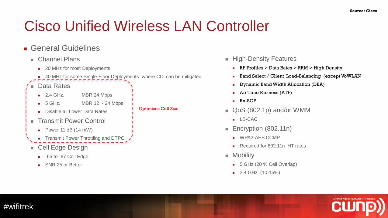
Cisco Unified Wireless LAN Controller
General Guidelines
Channel Plans
20 MHz for most Deployments
40 MHz for some Single-Floor Deployments where CCI can be mitigated
Data Rates
2.4 GHz. MBR 24 Mbps
5 GHz. MBR 12 - 24 Mbps
Disable all Lower Data Rates
Transmit Power Control
Power 11 dB (14 mW)
Transmit Power Throttling and DTPC
Cell Edge Design
-65 to -67 Cell Edge
SNR 25 or Better
Source: Cisco
High-Density Features
RF Profiles > Data Rates > RRM > High Density
Band Select / Client Load-Balancing (except VoWLAN
Dynamic Band Width Allocation (DBA)
Air Time Fairness (ATF)
Rx-SOP
QoS (802.1p) and/or WMM
LB-CAC
Encryption (802.11n)
WPA2-AES CCMP
Required for 802.11n HT rates
Mobility
5 GHz (20 % Cell Overlap)
2.4 GHz. (10-15%)
Optimizes Cell Size
#wifitrek
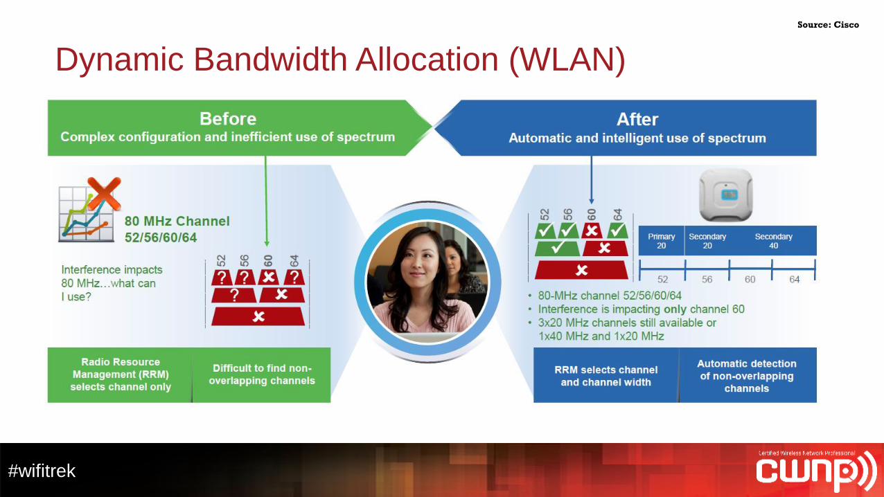
Dynamic Bandwidth Allocation (WLAN)
Source: Cisco
#wifitrek
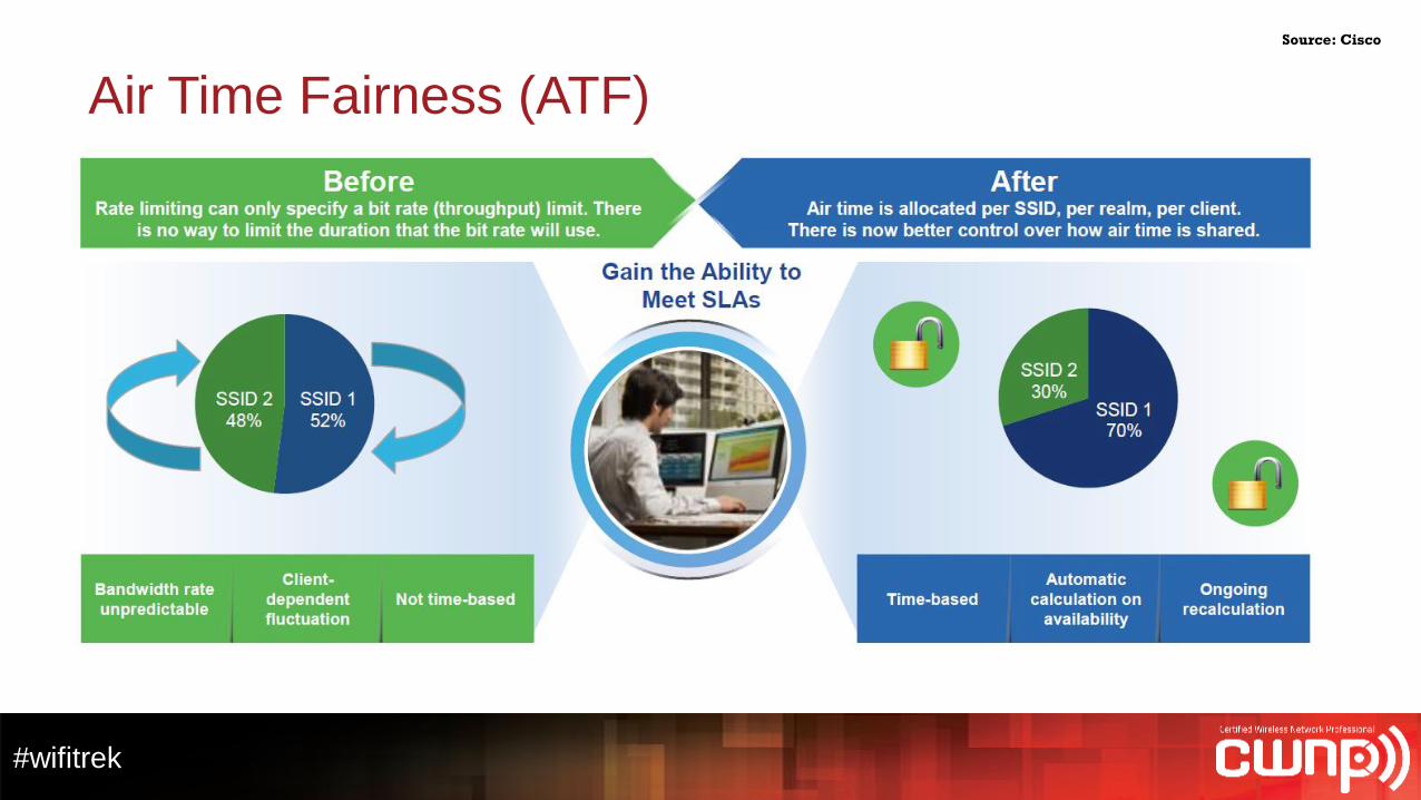
Air Time Fairness (ATF)
Source: Cisco
#wifitrek
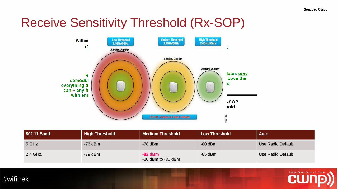
Receive Sensitivity Threshold (Rx-SOP)
802.11 Band High Threshold Medium Threshold Low Threshold Auto
5 GHz -76 dBm -78 dBm -80 dBm Use Radio Default
2.4 GHz. -79 dBm -82 dBm
-20 dBm to -81 dBm
-85 dBm Use Radio Default
Source: Cisco
#wifitrek
Special Thanks to:
Jerome Henry, Cisco
Fredrick Niehaus, Cisco
Jim Florwick, Cisco
Samuel Clements, Presidio
Scott Fella, CDW
Andrew Von Nagy
Erik Klaubert and Kit Johnson, Dimension Data