ex-0017-000002-pce - washington savage/adjudication/exhibits/tesoro/exhibit... · efsec application...
TRANSCRIPT
f) BergerABAM 210 East 13th Street, Suite 300, Vancouver, Washington 98660-3231 360/823-6100 • 360/823-6101 Fax • www.abam.com
10 March 2015
Mr. Stephen Posner Energy Facility Site Evaluation Council Washington Utilities and Transportation Commission P.O. Box 43172 Olympia, WA 98504-3172
Subject: Vancouver Energy EFSEC Application No. 2013-01, Docket No. EF131590 Response to EFSEC Draft EIS Data Request 4
Dear Mr. Posner:
On behalf of Tesoro Savage Petroleum Terminal LLC (the Applicant), BergerABAM is providing a response to the Energy Facility Site Evaluation Council's (EFSEC) Draft EIS Data Request 4, dated 9 February 2015.
Please feel free to contact me at 206/431-2373, or [email protected], if you have any questions about this submittal. We look forward to further coordination with you, your staff, and EFSEC' s consultants.
Sincerely,
Irina Makarow Senior Environmental Project Manager
IM:nb Attachment
cc: Kelly Flint, Savage Companies Jay Derr, Van Ness Feldman
EX-0017-000001-PCE

EX-0017-000002-PCE
Response to EFSEC Draft EIS Data Request 4
Code Data Request Item
Seismic Analysis
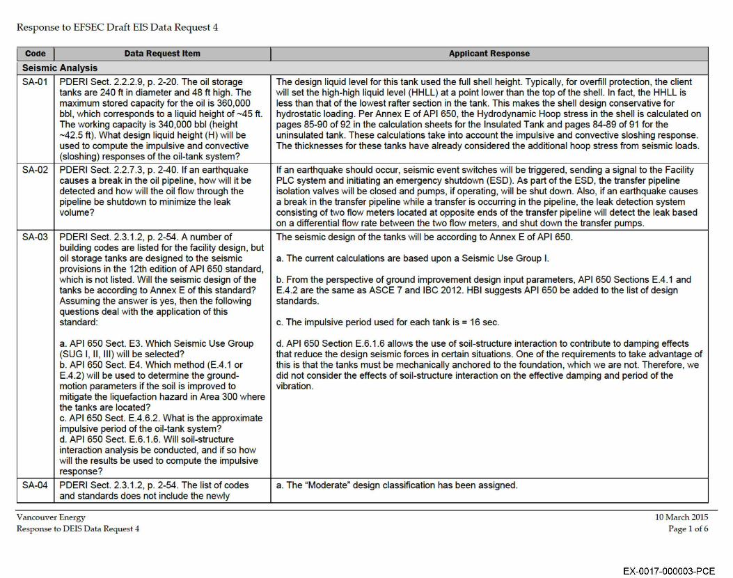
SA-01 PDERI Sect. 2.2.2.9, p. 2-20. The oil storage tanks are 240 ft in diameter and 48 ft high. The maximum stored capacity for the oil is 360,000 bbl, which corresponds to a liquid height of -45 ft. The working capacity is 340,000 bbl (height -42.5 ft). What design liquid height (H) will be used to compute the impulsive and convective (sloshing) responses of the oil-tank system?
SA-02 PDERI Sect. 2.2.7.3, p. 2-40. If an earthquake causes a break in the oil pipeline, how will it be detected and how will the oil flow through the pipel ine be shutdown to minimize the leak volume?
SA-03 PDERI Sect. 2.3.1.2, p. 2-54. A number of building codes are listed for the facility design, but oil storage tanks are designed to the seismic provisions in the 12th edition of API 650 standard, which is not listed. Will the seismic design of the tanks be according to Annex E of th is standard? Assuming the answer is yes, then the following questions deal with the application of th is standard:
SA-04
a. API 650 Sect. E3. Which Seismic Use Group (SUG I, II, Ill ) will be selected? b. API 650 Sect. E4. Which method (E.4 .1 or E.4.2) will be used to determine the groundmotion parameters if the soil is improved to mitigate the liquefaction hazard in Area 300 where the tanks are located? c. API 650 Sect. E.4.6.2. What is the approximate impulsive period of the oil-tank system? d. API 650 Sect. E.6.1.6. Will soil-structure interaction analysis be conducted , and if so how wil l the results be used to compute the impulsive response?
PDERI Sect. 2.3. 1.2, p. 2-54. The list of codes and standards does not include the newly
Vancouver Energy Response to DEIS Data Request 4
Applicant Response
The design liquid level for th is tank used the full shell height. Typically, for overfi ll protection, the cl ient will set the high-high liquid level (HHLL) at a point lower than the top of the shel l. In fact, the HHLL is less than that of the lowest rafter section in the tank. This makes the shell design conservative for hydrostatic loading. Per Annex E of API 650, the Hydrodynamic Hoop stress in the shell is calculated on pages 85-90 of 92 in the calculation sheets for the Insulated Tank and pages 84-89 of 91 for the uninsulated tank. These calculations take into account the impulsive and convective sloshing response. The th icknesses for these tanks have already considered the additional hoop stress from seismic loads.
If an earthquake should occur, seismic event switches will be triggered, sending a signal to the Facility PLC system and initiating an emergency shutdown (ESD). As part of the ESD, the transfer pipeline isolation valves will be closed and pumps, if operating, will be shut down. Also, if an earthquake causes a break in the transfer pipeline while a transfer is occurring in the pipeline, the leak detection system consisting of two flow meters located at opposite ends of the transfer pipeline will detect the leak based on a differential flow rate between the two flow meters, and shut down the transfer pumps.
The seismic design of the tanks will be according to Annex E of API 650.
a. The current calculations are based upon a Seismic Use Group I.
b. From the perspective of ground improvement design input parameters, API 650 Sections E.4.1 and E.4.2 are the same as ASCE 7 and IBC 2012. HSI suggests API 650 be added to the list of design standards.
c. The impulsive period used for each tank is = 16 sec.
d. API 650 Section E.6.1.6 allows the use of soil-structure interaction to contribute to damping effects that reduce the design seismic forces in certain situations. One of the requirements to take advantage of th is is that the tanks must be mechanically anchored to the foundation, which we are not. Therefore, we did not consider the effects of soil-structure interaction on the effective damping and period of the vibration.
a. The "Moderate" design classification has been assigned.
10 March 2015 Page 1 of6
EX-0017-000003-PCE
Response to EFSEC Draft EIS Data Request 4
Code Data Request Item
Seismic Analysis
SA-05
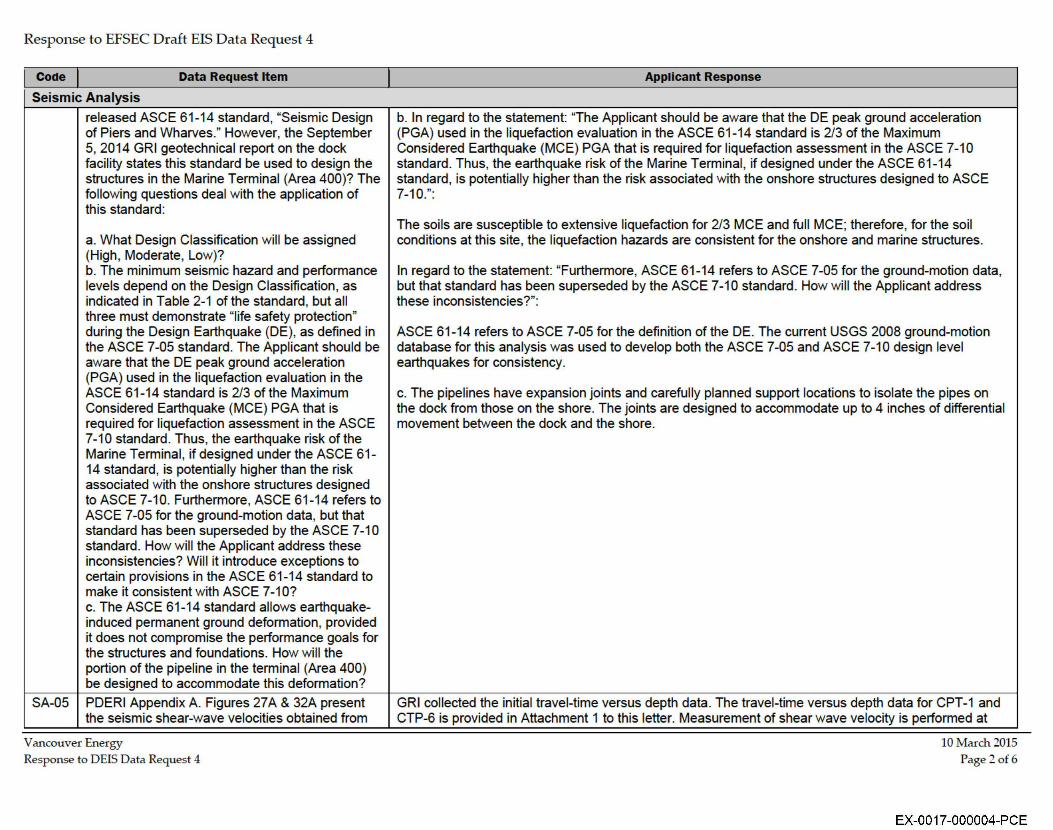
released ASCE 61-14 standard, "Seismic Design of Piers and Wharves." However, the September 5, 2014 GRI geotechnical report on the dock facility states th is standard be used to design the structures in the Marine Terminal (Area 400)? The following questions deal with the application of th is standard:
a. What Design Classification will be assigned (High, Moderate, Low)? b. The minimum seismic hazard and performance levels depend on the Design Classification, as indicated in Table 2-1 of the standard, but all three must demonstrate "life safety protection" during the Design Earthquake (DE), as defined in the ASCE 7-05 standard. The Applicant should be aware that the DE peak ground acceleration (PGA) used in the liquefaction evaluation in the ASCE 61-14 standard is 2/3 of the Maximum Considered Earthquake (MCE) PGA that is required for liquefaction assessment in the ASCE 7-10 standard. Thus, the earthquake risk of the Marine Terminal, if designed under the ASCE 61-14 standard, is potentially higher than the risk associated with the onshore structures designed to ASCE 7-10. Furthermore, ASCE 61-14 refers to ASCE 7-05 for the ground-motion data, but that standard has been superseded by the ASCE 7-10 standard. How will the Applicant address these inconsistencies? Will it introduce exceptions to certain provisions in the ASCE 61-14 standard to make it consistent with ASCE 7-1 O? c. The ASCE 61-14 standard allows earthquakeinduced permanent ground deformation, provided it does not compromise the performance goals for the structures and foundations. How will the portion of the pipeline in the terminal (Area 400) be designed to accommodate this deformation?
PDERI Appendix A. Figures 27 A & 32A present the seismic shear-wave velocities obtained from
Vancouver Energy Response to DEIS Data Request 4
Applicant Response
b. In regard to the statement: "The Applicant should be aware that the DE peak ground acceleration (PGA) used in the liquefaction evaluation in the ASCE 61-14 standard is 213 of the Maximum Considered Earthquake (MCE) PGA that is required for liquefaction assessment in the ASCE 7-10 standard. Thus, the earthquake risk of the Marine Terminal, if designed under the ASCE 61-14 standard, is potentially higher than the risk associated with the onshore structures designed to ASCE 7-10.":
The soi ls are susceptible to extensive liquefaction for 213 MCE and fu ll MCE; therefore, for the soil conditions at this site, the liquefaction hazards are consistent for the onshore and marine structures.
In regard to the statement: "Furthermore, ASCE 61-14 refers to ASCE 7-05 for the ground-motion data, but that standard has been superseded by the ASCE 7-10 standard. How will the Applicant address these inconsistencies?":
ASCE 61-14 refers to ASCE 7-05 for the definition of the DE. The current USGS 2008 ground-motion database for this analysis was used to develop both the ASCE 7-05 and ASCE 7-10 design level earthquakes for consistency.
c. The pipelines have expansion joints and carefu lly planned support locations to isolate the pipes on the dock from those on the shore. The joints are designed to accommodate up to 4 inches of differential movement between the dock and the shore.
GRI collected the initial travel-time versus depth data. The travel-time versus depth data for CPT-1 and CTP-6 is provided in Attachment 1 to this letter. Measurement of shear wave velocity is performed at
10 March 2015 Page 2of 6
EX-0017-000004-PCE
Response to EFSEC Draft EIS Data Request 4
Code Data Request Item
Seismic Analysis
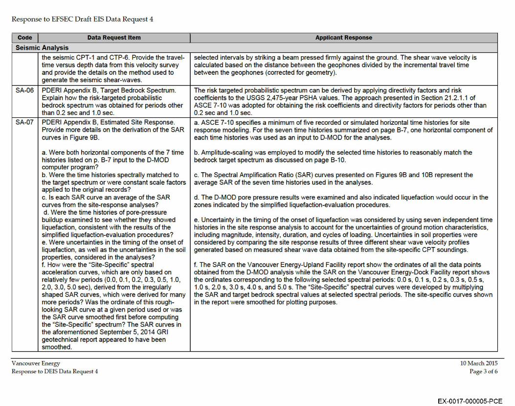
the seismic CPT-1 and CTP-6. Provide the traveltime versus depth data from this velocity survey and provide the details on the method used to generate the seismic shear-waves.
SA-06 PDERI Appendix B, Target Bedrock Spectrum. Explain how the risk-targeted probabil istic bedrock spectrum was obtained for periods other than 0.2 sec and 1.0 sec.
SA-07 PDERI Appendix B, Estimated Site Response. Provide more details on the derivation of the SAR curves in Figure 9B.
a. Were both horizontal components of the 7 time histories listed on p. B-7 input to the D-MOD computer program? b. Were the time histories spectrally matched to the target spectrum or were constant scale factors applied to the original records? c. Is each SAR curve an average of the SAR curves from the site-response analyses? d. Were the time histories of pore-pressure buildup examined to see whether they showed liquefaction, consistent with the results of the simplified liquefaction-evaluation procedures? e. Were uncertainties in the timing of the onset of liquefaction, as well as the uncertainties in the soil properties, considered in the analyses? f. How were the "Site-Specific" spectral acceleration curves , which are only based on relatively few periods (0.0, 0.1, 0.2, 0.3, 0.5, 1.0, 2.0, 3.0, 5.0 sec), derived from the irregularly shaped SAR curves, which were derived for many more periods? Was the ordinate of this roughlooking SAR curve at a given period used or was the SAR curve smoothed first before computing the "Site-Specific" spectrum? The SAR curves in the aforementioned September 5, 2014 GRI geotechnical report appeared to have been smoothed.
Vancouver Energy Response to DEIS Data Request 4
Applicant Response
selected intervals by striking a beam pressed firm ly against the ground. The shear wave velocity is calculated based on the distance between the geophones divided by the incremental travel time between the geophones (corrected for geometry).
The risk targeted probabilistic spectrum can be derived by applying directivity factors and risk coefficients to the USGS 2,475-year PSHA values. The approach presented in Section 21.2.1.1 of ASCE 7-10 was adopted for obtaining the risk coefficients and directivity factors for periods other than 0.2 sec and 1.0 sec.
a. ASCE 7-10 specifies a minimum of five recorded or simulated horizontal time histories for site response modeling. For the seven time histories summarized on page B-7, one horizontal component of each time histories was used as an input to D-MOD for the analyses.
b. Amplitude-scaling was employed to modify the selected time histories to reasonably match the bedrock target spectrum as discussed on page B-10.
c. The Spectral Ampl ification Ratio (SAR) curves presented on Figures 9B and 1 OB represent the average SAR of the seven time histories used in the analyses.
d. The D-MOD pore pressure results were examined and also indicated liquefaction would occur in the zones indicated by the simplified liquefaction-evaluation procedures.
e. Uncertainty in the timing of the onset of liquefaction was considered by using seven independent time histories in the site response analysis to account for the uncertainties of ground motion characteristics, including magnitude, intensity, duration, and cycles of loading. Uncertainties in soil properties were considered by comparing the site response results of three different shear wave velocity profiles generated based on measured shear wave data obtained from the site-specific CPT soundings.
f. The SAR on the Vancouver Energy-Upland Facility report show the ordinates of all the data points obtained from the D-MOD analysis while the SAR on the Vancouver Energy-Dock Facility report shows the ordinates corresponding to the following selected spectral periods: 0.0 s, 0.1 s, 0.2 s, 0.3 s, 0.5 s, 1.0 s, 2.0 s, 3.0 s, 4.0 s, and 5.0 s. The "Site-Specific" spectral curves were developed by multiplying the SAR and target bedrock spectral values at selected spectral periods. The site-specific curves shown in the report were smoothed for plotting purposes.
10 March 2015 Page 3 of 6
EX-0017-000005-PCE
Response to EFSEC Draft EIS Data Request 4
Code Data Request Item
Seismic Analysis
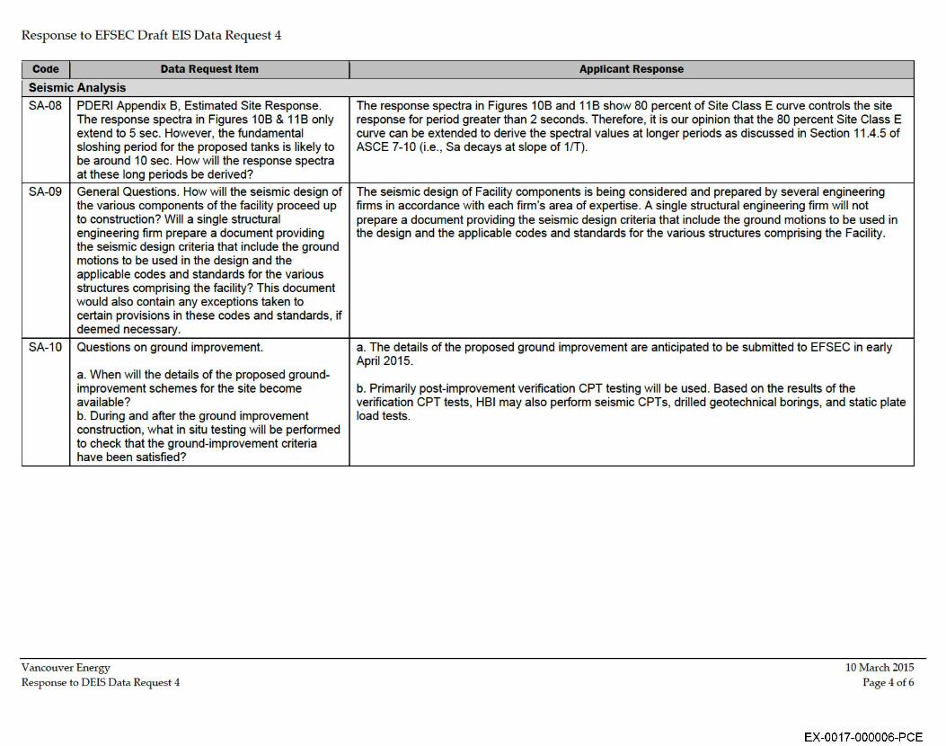
SA-08 PDERI Appendix B, Estimated Site Response. The response spectra in Figures 1 OB & 11 B only extend to 5 sec. However, the fundamental sloshing period for the proposed tanks is likely to be around 10 sec. How will the response spectra at these long periods be derived?
SA-09 General Questions. How will the seismic design of the various components of the facility proceed up to construction? W ill a single structural engineering firm prepare a document providing the seismic design criteria that include the ground motions to be used in the design and the appl icable codes and standards for the various structures comprising the facility? This document would also contain any exceptions taken to certain provisions in these codes and standards, if deemed necessary.
SA-10 Questions on ground improvement.
a. When wil l the details of the proposed ground-improvement schemes for the site become available? b. During and after the ground improvement construction , what in situ testing will be performed to check that the ground-improvement criteria have been satisfied?
Vancouver Energy Response to DEIS Data Request 4
Applicant Response
The response spectra in Figures 1 OB and 11 B show 80 percent of Site Class E curve controls the site response for period greater than 2 seconds. Therefore, it is our opinion that the 80 percent Site Class E curve can be extended to derive the spectral values at longer periods as discussed in Section 11.4.5 of ASCE 7-10 (i.e., Sa decays at slope of 1fT).
The seismic design of Faci lity components is being considered and prepared by several engineering firms in accordance with each firm 's area of expertise. A single structural engineering firm will not prepare a document providing the seismic design criteria that include the ground motions to be used in the design and the applicable codes and standards for the various structures comprising the Facility.
a. The detai ls of the proposed ground improvement are anticipated to be submitted to EFSEC in early April 2015.
b. Primarily post-improvement verification CPT testing will be used. Based on the results of the verification CPT tests, HSI may also perform seismic CPTs, dril led geotechnical borings, and static plate load tests.
10 March 2015 Page 4of 6
EX-0017-000006-PCE
Response to EFSEC Draft EIS Data Request 4
Code Data Request Item
Seismic Analysis
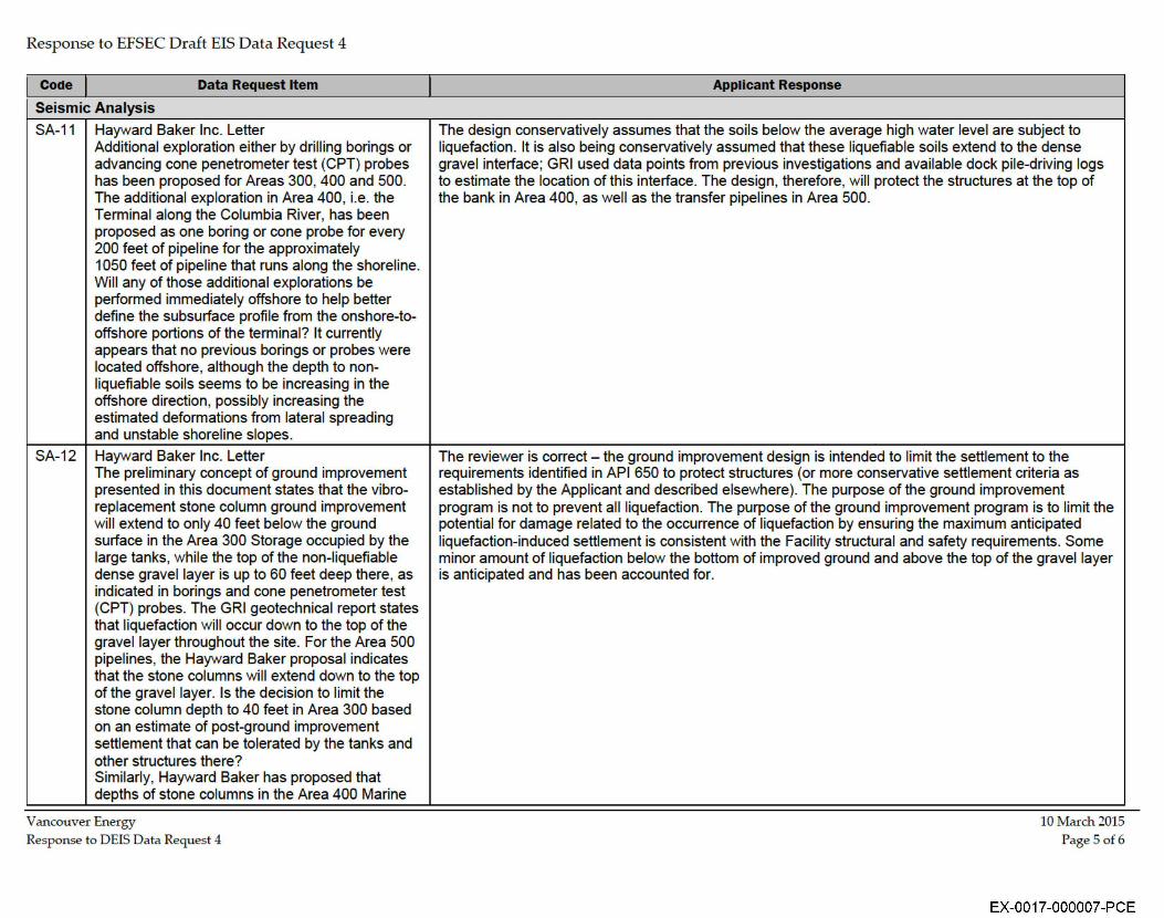
SA-11 Hayward Baker Inc. Letter Additional exploration either by drill ing borings or advancing cone penetrometer test (CPT) probes has been proposed for Areas 300, 400 and 500. The additional exploration in Area 400, i.e. the Terminal along the Columbia River, has been proposed as one boring or cone probe for every 200 feet of pipeline for the approximately 1050 feet of pipel ine that runs along the shoreline. Will any of those additional explorations be performed immediately offshore to help better define the subsurface profi le from the onshore-tooffshore portions of the terminal? It currently appears that no previous borings or probes were located offshore, although the depth to nonliquefiable soils seems to be increasing in the offshore direction, possibly increasing the estimated deformations from lateral spreading and unstable shoreline slopes.
SA-12 Hayward Baker Inc. Letter The preliminary concept of ground improvement presented in this document states that the vibroreplacement stone column ground improvement wi ll extend to only 40 feet below the ground surface in the Area 300 Storage occupied by the large tanks, while the top of the non-liquefiable dense gravel layer is up to 60 feet deep there , as indicated in borings and cone penetrometer test (CPT) probes. The GRI geotechnical report states that liquefaction will occur down to the top of the gravel layer throughout the site. For the Area 500 pipelines, the Hayward Baker proposal indicates that the stone columns wi ll extend down to the top of the gravel layer. Is the decision to limit the stone column depth to 40 feet in Area 300 based on an estimate of post-ground improvement settlement that can be tolerated by the tanks and other structures there? Similarly, Hayward Baker has proposed that depths of stone columns in the Area 400 Marine
Vancouver Energy Response to DEIS Data Request 4
Applicant Response
The design conservatively assumes that the soils below the average high water level are subject to liquefaction. It is also being conservatively assumed that these liquefiable soils extend to the dense gravel interface; GRI used data points from previous investigations and available dock pile-driving logs to estimate the location of th is interface. The design, therefore, will protect the structures at the top of the bank in Area 400, as well as the transfer pipelines in Area 500.
The reviewer is correct - the ground improvement design is intended to limit the settlement to the requirements identified in API 650 to protect structures (or more conservative settlement criteria as established by the Applicant and described elsewhere). The purpose of the ground improvement program is not to prevent all liquefaction. The purpose of the ground improvement program is to limit the potential for damage related to the occurrence of liquefaction by ensuring the maximum anticipated liquefaction-induced settlement is consistent with the Facility structural and safety requ irements. Some minor amount of liquefaction below the bottom of improved ground and above the top of the gravel layer is anticipated and has been accounted for.
10 March 2015 Page 5 of 6
EX-0017-000007-PCE
Response to EFSEC Draft EIS Data Request 4
Code Data Request Item
Seismic Analysis
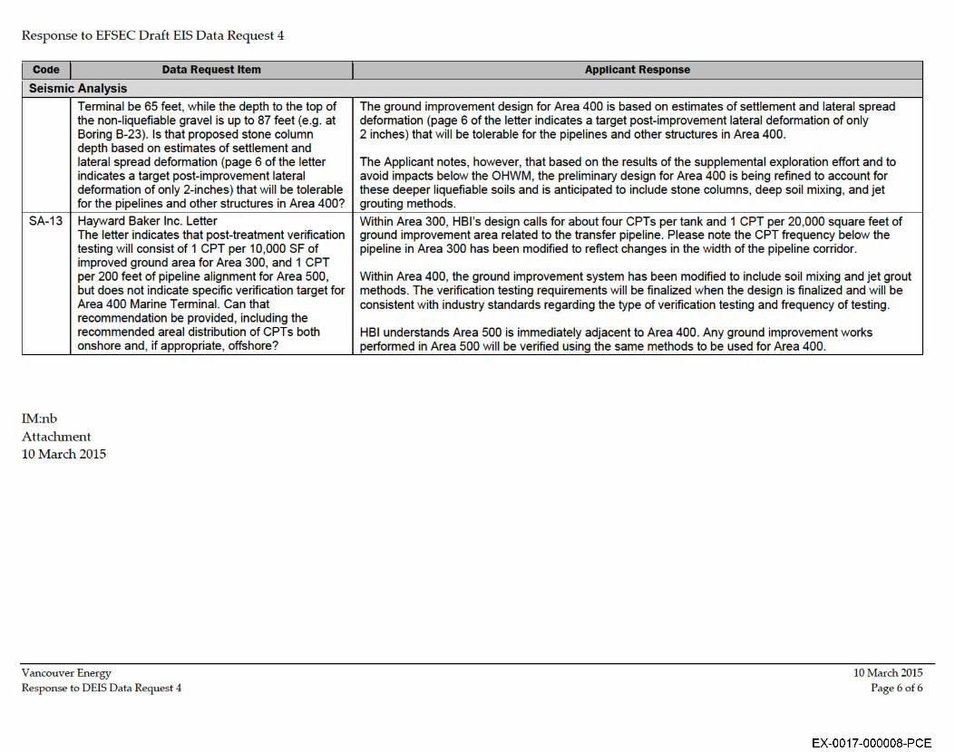
Terminal be 65 feet, while the depth to the top of the non-liquefiable gravel is up to 87 feet (e.g. at Boring B-23). Is that proposed stone column depth based on estimates of settlement and lateral spread deformation (page 6 of the letter indicates a target post-improvement lateral deformation of only 2-inches) that will be tolerable for the pipelines and other structures in Area 400?
SA-13 Hayward Baker Inc. Letter The letter indicates that post-treatment verification testing will consist of 1 CPT per 10,000 SF of improved ground area for Area 300, and 1 CPT per 200 feet of pipeline alignment for Area 500, but does not indicate specific verification target for Area 400 Marine Terminal. Can that recommendation be provided, including the recommended areal distribution of CPTs both onshore and, if appropriate, offshore?
IM:nb Attachment 10 March 2015
Vancouver Energy Response to DEIS Data Request 4
Applicant Response
The ground improvement design for Area 400 is based on estimates of settlement and lateral spread deformation (page 6 of the letter indicates a target post-improvement lateral deformation of only 2 inches) that will be tolerable for the pipelines and other structures in Area 400.
The Applicant notes, however, that based on the results of the supplemental exploration effort and to avoid impacts below the OHWM, the preliminary design for Area 400 is being refined to account for these deeper liquefiable soils and is anticipated to include stone columns, deep soil mixing, and jet grouting methods.
Within Area 300, HBl's design calls for about four CPTs per tank and 1 CPT per 20,000 square feet of ground improvement area related to the transfer pipeline. Please note the CPT frequency below the pipeline in Area 300 has been modified to reflect changes in the width of the pipeline corridor.
Within Area 400, the ground improvement system has been modified to include soil mixing and jet grout methods. The verification testing requirements will be finalized when the design is finalized and will be consistent with industry standards regarding the type of verification testing and frequency of testing.
HBI understands Area 500 is immediately adjacent to Area 400. Any ground improvement works performed in Area 500 will be verified using the same methods to be used for Area 400.
10 March 2015 Page 60£ 6
EX-0017-000008-PCE
Response to EFSEC Draft EIS Data Request 4
Attachment 1
Vancouver Energy 10 March 2015 Response to DEIS Data Request 4
EX-0017-000009-PCE
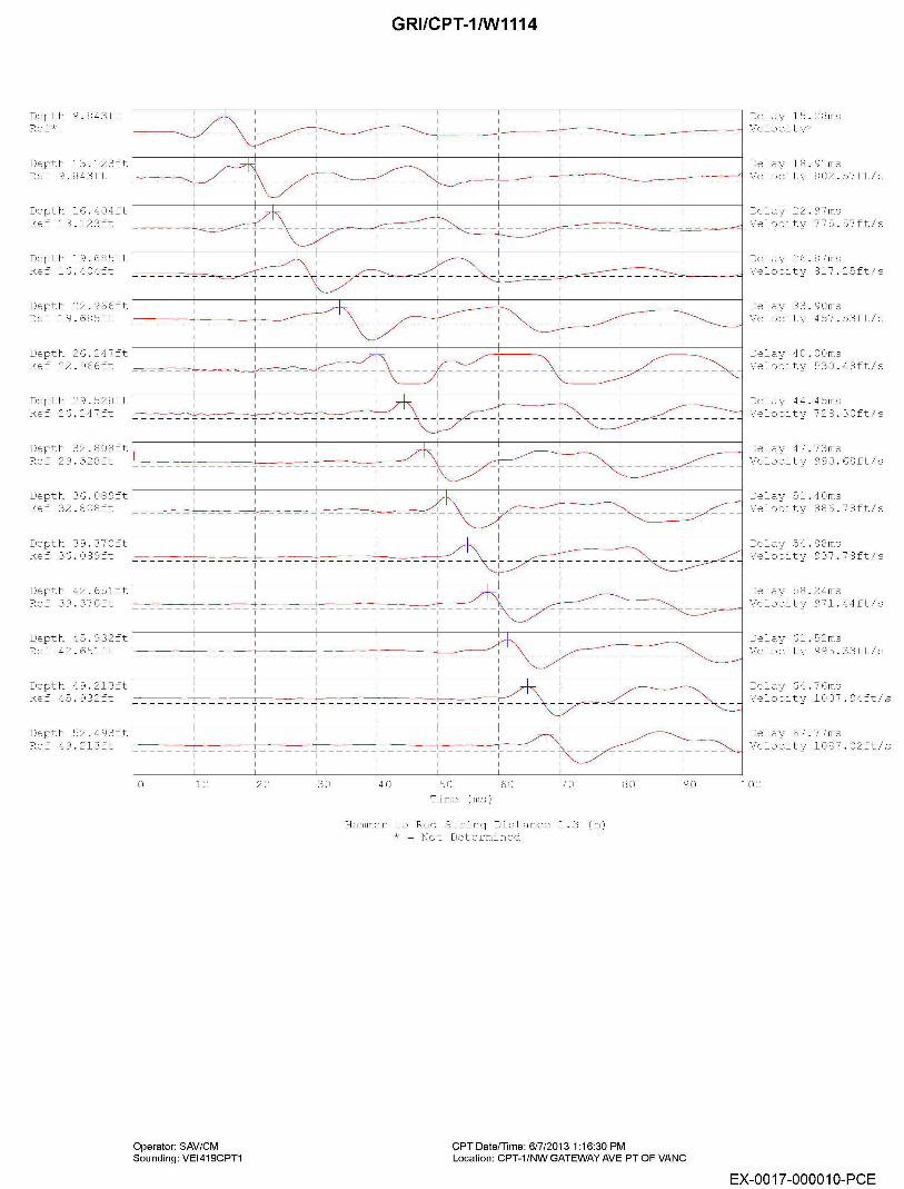
Depth 9.843ft Ref*
Depth 13.123ft Ref 9.843ft
Depth 16.404ft Ref 13.123ft
Depth 19.685ft Ref 16.404ft
Depth 22. 966ft
F--=---_,_J_ _____ J_ __ _ I
GRl/CPT-1/W1114
Delay 15.08ms
- -
1
- - - - - ----~'=-~-~-=-~-=--~-------=_-c_c-_tc, -::_:-:_~_-:_-_:=- _-'-~~~-~-~, =- -c_c-_=-=_cc_=-=- --i Velocity*
Delay 18.9lms
~~-~~-~-=-=--=_:-:_::-C_~-~---~-~-----~-~----~-~-~-=-=-----=-=--~--'1 Velocity 802.57ft/s
Delay 22.97ms I
---------- 1 ______ 1 _ --~-=-~-T-' -=-~-~-~-i Velocity 77 5. 57 ft/ s
Delay 26.87ms
~=-=.:::.-~==-r~~- ___ -+- ____ -~-,------"'! Velocity 81 7. 25ft/ s
Ref 19.685ft ---------------------'---- ___________ L _____ L _____ l ______ _I __ _
Delay 33.90ms Velocity 457.53ft/s
Depth 26.247ft Ref 22. 966ft
Depth 29.528ft Ref 26.247ft
Depth 32.808ft Ref 29.528ft
Depth 36.089ft Ref 32.808ft
Depth 39.370ft Ref 36.089ft
Depth 42.65lft Ref 39.370ft
Depth 45.932ft
' I I I I I I
I I ------------,------'
Delay 40.00ms Velocity 530.48ft/s
Delay 44.45ms
------,-------,--------,------~----1 1 Velocity 728.30ft/s
---i-- ---,------
----------------------------------! I I I
- - - - - -1- - - - - -,- - - - - -,- - - - - - -1- - - - - - -1- - - - - - -
I 1------
______ L ____________ J __ I I
' ~----r-----1 I ---,----------'
Delay 47.73ms Velocity 990.68ft/s
Delay 51.40ms Velocity 886.78ft/s
Delay 54.88ms Velocity 937.78ft/s
Delay 58.24ms Velocity 971.44ft/s
Delay 61.52ms Ref 42.65lft 1 1 1 Velocity 995.33ft/s
Depth 49.213ft Ref 45. 932ft
Depth 52.493ft Ref 4 9. 213ft
- - - - - -1- - - - - - , - - - - - - , - - - - - - -1- - - - - - -1- - - - - - -1- - - ------i------,------
-----------------------------------------------! I I I I I
-----------------------------------~-------------
0 10 20 30 40 50 60 70 Time (ms)
Hammer to Rod String Distance 1.3 (m) * = Not Determined
80
CPTDate/Time: 6/7/20131:16:30 PM
90
Operator: SAV/CM Sounding: VEl419CPT1 Location: CPT-1/NW GATEWAY AVE PT OF VANG
Delay 64.76ms Velocity 1007.94ft/s
Delay 67.77ms Velocity 1087.02ft/s
100
EX-0017-000010-PCE
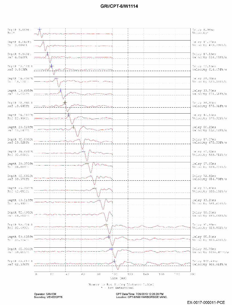
GRl/CPT-6/W1114
Delay 6.99ms Depth 3.609ft Ref* f'--L'--L~~~~~c0-----~-~-~---=-='-~---------~-~-~---------~-~: - ______ , _______ 1_ ______ l ______ _1 _ _ _ _ _ _ Velocity*
I I I I I I I I
Depth 6.562ft Ref 3.609ft
Depth 9.843ft Ref 6.562ft
Depth 13.123ft Ref 9.843ft
Depth 16.404ft Ref 13.123ft
I I I I I
---------------------------,------
I ------i------
I ------i------
'
------------- ------______ _!__ _____ _
Depth 19.685ft Ref 16.404ft
Depth 22. 966ft Ref 19.685ft
Depth 26.247ft Ref 22. 966ft
' I
I I I I I
----------------------------------,------
'
Depth 45.932ft 1 Ref 4 2. 651 ft r---~--, ~---~, ----~, ~~
I I I I I
--------------------,-------- ---------------------------------,------
' '
I I I I I I I ------1------,------,------ - - -1- - - - - - -1- - - - - - -1- - - - - - I - - - - - -1- - - - - -
Depth 52.493ft Ref 4 9. 213ft c---------__,," 1 1 I I I I ------1------,------,------ - - -1- - - - - - -1- - - - - - -1- - - - - - I - - - - - -1- - - - - -
Depth 55. 77 4 ft Ref 5 2 . 4 9 3 ft v---_-_-_-_-_-_-_~, -_-_-_-_~_~_-_-, -_-_-_-_-_-_-_~, -_-_-_~_<_-_~~-
' I I
Depth 59.055ft 1 Ref 5 5 . 77 4 ft 1----~~~, -~-./'----'-, -~~~---0-, -~-----""~'--"
--------------------,------
' Depth 62.336ft Ref 59.055ft '--~~~~,~~-_,---c', ~-~---,__,~~--c-----''-/
------1------,------,------
Depth 65.617ft Ref 62. 33 6 ft f-----~<, .__,..._,~-~-,~~~------~~~~~~~~-~~
------1------,------,------
0 20
Operator: SAV/CM Sounding: VEl422CPT6
40 60 80 100 120 140 Time (ms)
Hammer to Rod String Distance l.3(m) * ~ Not Determined
160
CPT Date/Time: 7/29/2013 12:26:29 PM Location: CPT-6/NW HARBORSIDE VANG.
180
Delay 11. 72ms Velocity 473.73ft/s
Delay 17.15ms Velocity 534.29ft/s
Delay 22.15ms Velocity 614.47ft/s
Delay 28.20ms Velocity 520.38ft/s
Delay 33.79ms Velocity 571.5lft/s
Delay 39.37ms Velocity 575.9lft/s
Delay 44.14ms Velocity 678.32ft/s
Delay 50.23ms Velocity 532.22ft/s
Delay 57.07ms Velocity 475.53ft/s
Delay 62.93ms Velocity 555.7lft/s
Delay 67.65ms Velocity 689.77ft/s
Delay 72.42ms Velocity 684.78ft/s
Delay 77.42ms Velocity 653.18ft/s
Delay 83.24ms Velocity 561.47ft/s
Delay 88.04ms Velocity 680.49ft/s
Delay 91.99ms Velocity 829.06ft/s
Delay 95.54ms Velocity 920.48ft/s
Delay 98.70ms Velocity 1034.42ft/s
Delay 102.49ms Velocity 864.0lft/s
200
EX-0017-000011-PCE
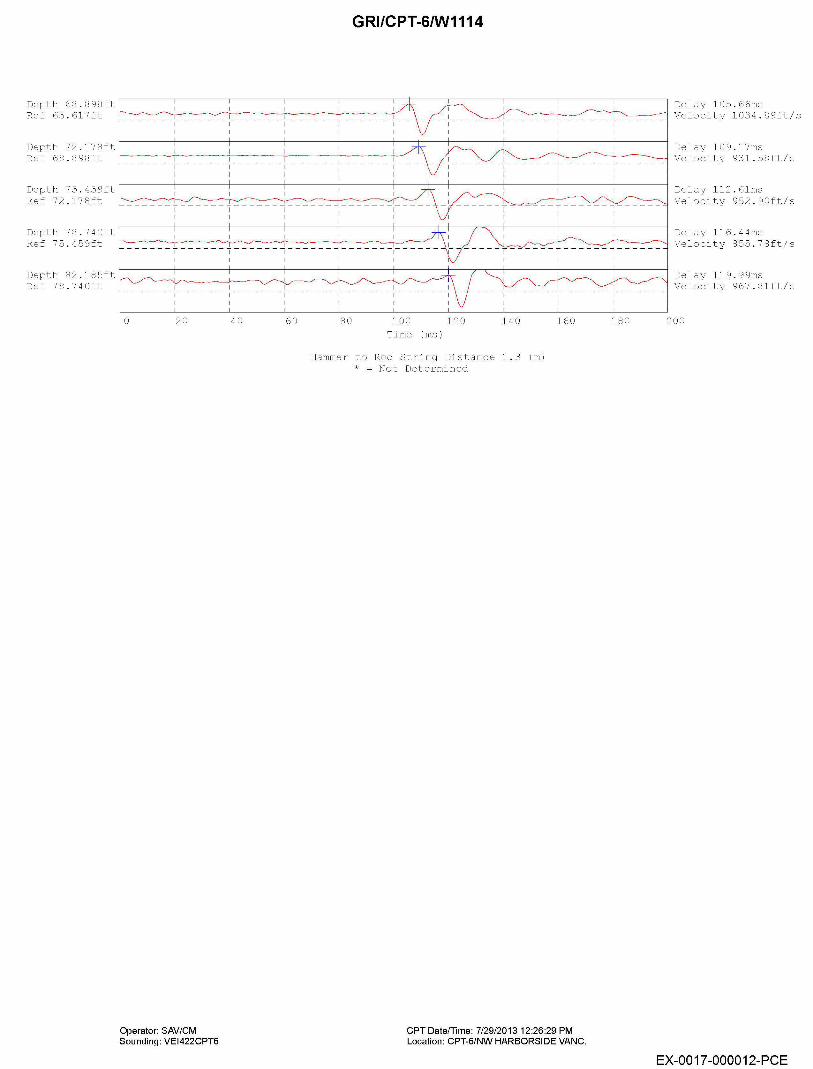
GRl/CPT-6/W1114
Depth 68.898ft Ref 6 5 . 617 ft r---_-_~_-_-_~_~_-_-_-_-_---_~_-_,_, -_-_-_-_-_-_---,_,-_-_-_-_-_-_-_.,.._-_-_-_-_-_---,---
Delay 105.66ms ~~-~__,,,-----;--..___ __ _-~ Velocity 1034.89ft/s
1 I I I
Depth 72.178ft 1 Ref 68. 8 98 ft ~-----, -----, -----, ----------~
--------------------,------
' Depth 75.459ft Ref 72.178ft i----------~'-"", ---~..__~-,-, ~-~-~-~--....-----------0
------y------T------~------~------
Depth 78. 740ft Ref 75.459ft r--~~~~--~~-~---;---~~--.---~-----~~-~
Depth 82.185ft Ref 78.740ft
0 20 40 60 80 100 Time (ms)
120 140
Hammer to Rod String Distance 1.3 (m) * ~ Not Determined
160
Operator: SAV/CM Sounding: VEl422CPT6
CPT Date/Time: 7/29/2013 12:26:29 PM Location: CPT-6/NW HARBORSIDE VANG.
Delay 109.17ms Velocity 931.58ft/s
Delay 112.6lms Velocity 952.90ft/s
Delay 116.44ms ~-.------i Velocity 855.78ft/s
180
Delay 119.99ms Velocity 967.8lft/s
200
EX-0017-000012-PCE