ex-safety and main current switches 2 starters, reversing starters ... the manual motor starter: it...
TRANSCRIPT

10.84EX-MANUAL MOTOR STARTERS
10.58EX-MAIN CURRENT SWITCHES
10.34INDUSTRIAL SAFETY SWITCHES
10.41EX-SAFETY SWITCHES
10.21APPLICATIONS
E X - S A F E T Y A N D
M A I N C U R R E N T S W I T C H E S
10.70EX-POWER CIRCUIT BREAKERS
1
2
3
4
5
6
7
8
9
10
11
12
10.2 C O O P E R C R O U S E - H I N D S G M B H
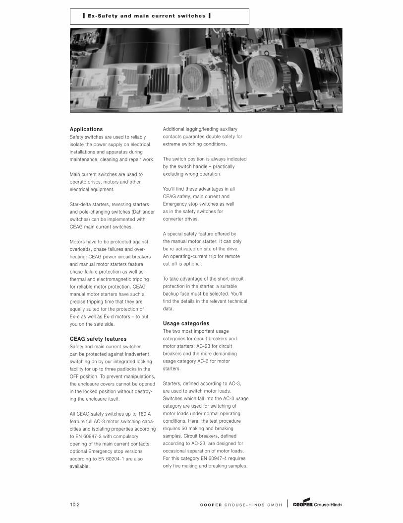
I Ex-Safety and main current switches I
Applications
Safety switches are used to reliably
isolate the power supply on elec trical
installations and apparatus during
maintenance, cleaning and repair work.
Main current switches are used to
operate drives, motors and other
electrical equipment.
Star-delta starters, reversing starters
and pole-changing switches (Dahlander
switches) can be im plemented with
CEAG main current switches.
Motors have to be protected against
over loads, phase failures and over -
heating: CEAG power circuit breakers
and manual motor starters feature
phase-failure protection as well as
thermal and electromagnetic tripping
for reliable motor protection. CEAG
manual motor starters have such a
precise tripping time that they are
equally suited for the protection of
Ex-e as well as Ex-d motors – to put
you on the safe side.
CEAG safety features
Safety and main current switches
can be protected against inadvertent
switching on by our integrated locking
facility for up to three padlocks in the
OFF position. To prevent manipulations,
the enclosure covers cannot be opened
in the locked position without destroy-
ing the enclosure itself.
All CEAG safety switches up to 180 A
feature full AC-3 motor switching capa-
cities and isolating properties according
to EN 60947-3 with compulsory
opening of the main current contacts;
optional Emergency stop versions
according to EN 60204-1 are also
available.
Additional lagging/leading auxiliary
contacts guarantee double safety for
extreme switching conditions.
The switch position is always indicated
by the switch handle – practically
excluding wrong operation.
You'll find these advantages in all
CEAG safety, main current and
Emergency stop switches as well
as in the safety switches for
converter drives.
A special safety feature offered by
the manual motor starter: It can only
be re-activated on site of the drive.
An operating-current trip for remote
cut-off is optional.
To take advantage of the short-circuit
protection in the starter, a suitable
backup fuse must be selected. You'll
find the details in the relevant technical
data.
Usage categories
The two most important usage
categories for circuit breakers and
motor starters: AC-23 for circuit
breakers and the more demanding
usage category AC-3 for motor
starters.
Starters, defined according to AC-3,
are used to switch motor loads.
Switches which fall into the AC-3 usage
category are used for switching of
motor loads under normal operating
conditions. Here, the test procedure
requires 50 making and breaking
samples. Circuit breakers, defined
according to AC-23, are designed for
occasional separation of motor loads.
For this category EN 60947-4 requires
only five making and breaking samples.

C O O P E R C R O U S E - H I N D S G M B H 10.3
I Ex-Safety and main current switches I
The AC-3 usage category makes great
demands on the operating cycles and
the service life of motor starters. All
CEAG safety switches and manual
motor starters up to 180 A fulfill these
high requirements for the motor-
switching capacity of usage category
AC-3 as specified by EN 60947-4-1.
Areas of application
We offer you a wide range of products
in all areas: explosion-protected
apparatus for gas and dust areas
as well as for industrial applications
in rough environments.
Material
Both explosion-protected as well as
industrial switches are provided in
impact-resistant polyamide, glass-fibre-
reinforced polyester, powder-coated
steel, high-grade stainless steel or
flameproof enclosures made of light
alloy, depending on the area of
application and amperage.
All explosion-protected switches
are certified according to the ATEX
directive.
Mounting
Switches up to 180 A can be mounted
simply and quickly with the CEAG
mounting system to pipes, trellis work
and walls. What's more, CEAG
switches up to 40 A offer low-cost
mounting – in a snap – with the
snap-on system.
1
2
3
4
5
6
7
8
9
10
11
12

Full AC-3 switching capacity
Double safety: additional auxiliary contact
Cost-saving installation up to 180 A
Snap-on mounting up to 40 A
IP66 protection up to 180 A
10.4
E X - S A F E T Y S W I T C H E S
CEAG safety switches can be protected against
inadvertent switching on by our integrated
locking facility for up to three padlocks in the
OFF position. To prevent manipulations, the
enclosure covers cannot be opened in the
locked position without destroying the enclosure
itself.
All CEAG safety switches feature full AC-3 motor
switching capacities and isolating properties
according to EN 60947-4-1 with compulsory
opening of the main current contacts; optional
EMERGENCY STOP versions according to
EN 60204-1 are also available.
Additional lagging/leading auxiliary contacts
guarantee double safety for extreme switching
conditions.
The safety switches feature an installation-
friendly design and easily accessible connection
terminals.
Versions in impact-resistant polyamide or glass-
fibre-reinforced polyester enclosures provide
the high degree of protection IP66 for safety
switches up 180 A. These can be optionally
supplied with snap-on moulded plastic or
brass flanges. Safety switches for amperages
up to 630 A are supplied in metal enclosures.
These can be equipped with screw-on flanges.
The described safety switches at the sizes
210 - 630 A are also available for Explosion
Group IIB, which is sufficient for many of
the applications.
Internationally approved.
Up to 630 A

I Ex-Safety switches I
C O O P E R C R O U S E - H I N D S G M B H 10.5
Technical data
Ex-Safety switch 10 A
Marking to 94/9/EC II 2 G Ex ed IIC T6 / II 2 D Ex tD A21 IP66 T80 °C
EC-Type Examination Certificate PTB 00 ATEX 1074
IECEx Certificate of Conformity BKI 07.0014
Marking accd. to IECEx Ex ed IIC T6
Ex tD A21 IP66 T53 °C
Permissible ambient temperature –20 °C to +40 °C1)
Rated voltage up to max. 500 V
Rated current max. 10 A
Frequency 50/60 Hz
Rated making-/breaking capacity AC-3 Ue 230 V / Ie 10 A
accd. to EN 60947-3 Ue 400 V / Ie 10 A
Ue 500 V / Ie 10 A
Back-up fuse up to 400 V AC: 20 A gL
up to 500 V AC: 16 A gL
Connecting terminals Main contact 2 x 1.5 - 2.5 mm2
Auxiliary-/Signal contact 2 x 0.5 - 2.5 mm2
Degree of protection accd. EN 60529 IP66
Insulation class I
Cable glands/enclosure drilling M20 (d = 5 - 13 mm) see ordering details
M25 (d = 8 - 17 mm) see ordering details
Weight 0.55 kg
Enclosure material impact resistant polyamide
Enclosure colour black
Auxiliary contact 1 x NO making - lagging; breaking - leading
Padlocking can be locked in OFF position with 3 commercially available padlocks
1) Other ambient temperatures on request
3-pole EMERGENCY STOP 3-pole
1
2
3
4
5
6
7
8
9
10
11
12

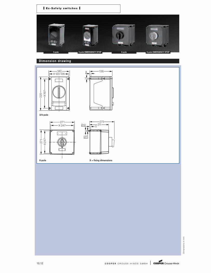
Dimensions
Dim
en
sio
ns
in
mm
3-pole X = fixing dimensions
10.6 C O O P E R C R O U S E - H I N D S G M B H
I Ex-Safety switches I
3-pole 3-pole EMERGENCY STOP
Ordering detai ls
Version Cable gland Order No.
3-pole 2 x M25 / 1 x M 20 GHG 261 0005 R0009
3-pole 2 x M20 GHG 261 0005 R0005
3-pole EMERGENCY STOP 2 x M25 / 1 x M 20 GHG 261 0005 R0010
Customized version on request, auxiliary contacts in Ex ia available
Accessories
Mounting plate for Ex-safety switch 10 A 3-pole
Type Application Fixing method Order No.
Size 1 Wall mounting screw-on GHG 610 1953 R0101
Size 1 Pipe mounting screw-on GHG 610 1953 R0102
Size 1 Trellis mounting screw-on GHG 610 1953 R0103
Accessories for mounting plates
Type OU Order No.
Label holder with label (unlabelled) for mounting plates size 1, 2, 2A and 3 10 GHG 610 1953 R0057
Installation kit for pipes 1” (of 27 - 30 mm) for label holder for pipe mounting 10 GHG 610 1953 R0020
Accessories for canopies plates
Type Application OU Order No.
Size 1 for mounting plates size 1 1 GHG 610 1955 R0101
Please note that we can only deliver in the ordering units (OU) stated in the tables above
102
X61.5
X68.5
84
80
112
Ø 5.5
Ø 8.5

I Ex-Safety switches I
C O O P E R C R O U S E - H I N D S G M B H 10.7
6-pole EMERGENCY STOP 6-pole 3-pole EMERGENCY STOP 3-pole
Technical data
Ex-Safety switch 20 A
Marking to 94/9/EC II 2 G Ex ed ia IIC T6 / II 2 D Ex tD A21 IP66 T80 °C
EC-Type Examination Certificate PTB 99 ATEX 1161
IECEx Certificate of Conformity BKI 07.0012
Marking accd. to IECEx Ex ed ia IIC T6
Ex tD A21 IP66 T55 °C
Permissible ambient temperature –20 °C to +40 °C1)
Rated voltage up to max. 690 V
Rated current max. 20 A
Frequency 50/60 Hz
Rated making-/breaking capacity AC-3 Ue 230 V / Ie 20 A
accd. to EN 60947-3 Ue 400 V / Ie 20 A
Ue 500 V / Ie 10 A
Ue 690 V / Ie 10 A
Back-up fuse up to 400 V AC: 35 A gL
up to 500 V AC: 35 A gL
up to 690 V AC: 25 A gL
Connecting terminals Main contact 2 x 4 mm2
Auxiliary-/Signal contact 2 x 0.5 - 2.5 mm2
Insulation class I
Degree of protection accd. EN 60529 IP66
Cable glands/enclosure drilling M20 (d = 5 - 13 mm) see ordering details
M25 (d = 8 - 17 mm) see ordering details
M32 (d = 12 - 21 mm) see ordering details
Option: metal flange with thread
Weight 3-pole approx. 1.48 kg
6-pole approx. 2.43 kg
Enclosure material glass-fibre reinforced polyester
Enclosure colour black
Auxiliary contact 1 x NO making - lagging; breaking - leading
1 x NC (only 6-pole version) making - leading; breaking - lagging
Padlocking can be locked in OFF position with 3 commercially available padlocks
1) Other ambient temperatures on request
1
2
3
4
5
6
7
8
9
10
11
12

10.8 C O O P E R C R O U S E - H I N D S G M B H
I Ex-Safety switches I
Ordering detai ls
Version Cable entry Order No.
Safety switch 20 A 3-pole
Version with 1 auxiliary contact (NO)
3-pole 2 x M32 / 1 x M25 GHG 262 2301 R0001
3-pole EMERGENCY STOP 2 x M32 / 1 x M25 GHG 262 2301 R0002
Safety switch 20 A 4-pole
Version with 2 auxiliary contact (1 x NO; 1 x NC)
4-pole 2 x M20 GHG 262 2301 R0007
4-pole EMERGENCY STOP 2 x M32 / 1 x M25 GHG 262 2301 R0010
Safety switch 20 A 6-pole
Version with 2 auxiliary contact (1 x NO; 1 x NC)
6-pole 4 x M32 / 1 x M25 GHG 262 2601 R0001
6-pole 4 x M25 GHG 262 2601 R0005
6-pole EMERGENCY STOP 4 x M32 / 1 x M25 GHG 262 2601 R0002
Customized version on request, auxiliary contacts in Ex ia available
3-pole 3-pole EMERGENCY STOP 6-pole 6-pole EMERGENCY STOP
Accessories
Mounting plate for Ex-safety switch 20 A 3-pole
Type Application Fixing technique Order No.
Size 2 Wall mounting snap-on GHG 610 1953 R0104
Size 2 Pipe mounting snap-on GHG 610 1953 R0105
Size 2 Trellis mounting snap-on GHG 610 1953 R0106
Mounting plate for Ex-safety switch 20 A 6-pole
Type Application Fixing technique Order No.
Size 3 Wall mounting snap-on GHG 610 1953 R0118
Size 3 Pipe mounting snap-on GHG 610 1953 R0110
Size 3 Trellis mounting snap-on GHG 610 1953 R0118
Accessories for mounting plates
Type OU Order No.
Label holder with label (unlabelled) for mounting plates size 1, 2, 2A and 3 10 GHG 610 1953 R0057
Installation kit for pipes 1” (of 27 - 30 mm) for mounting plates for pipe mounting 10 GHG 610 1953 R0020
Accessories for canopies plates
Type Application OU Order No.
Size 2 for mounting plates size 2 1 GHG 610 1955 R0102
Size 2A for mounting plates size 2A 1 GHG 610 1955 R0103
Size 3 for pipe mounting plate size 3 vertical 1 GHG 610 1955 R0104
Size 3A for wall/trellis mounting plate size 3 vertical 1 GHG 610 1955 R0105
Size 3B for pipe mounting plate size 3 horizontal 1 GHG 610 1955 R0106
Please note that we can only deliver in the ordering units (OU) stated in the tables above

C O O P E R C R O U S E - H I N D S G M B H 10.9
Dimension drawing
Dim
en
sio
ns
in
mm
3/4-pole
6-pole X = fixing dimensions
I Ex-Safety switches I
6-pole EMERGENCY STOP 6-pole 3-pole EMERGENCY STOP 3-pole
X150
X96
110
170
129
7
13
X197
X123-126
140
225
156
7
8
1
2
3
4
5
6
7
8
9
10
11
12

10.10 C O O P E R C R O U S E - H I N D S G M B H
I Ex-Safety switches I
3-pole 3-pole EMERGENCY STOP 6-pole 6-pole EMERGENCY STOP
Technical data
Ex-Safety switch 40 A
Marking to 94/9/EC II 2 G Ex ed ia IIC T6 / II 2 D Ex tD A21 IP66 T80 °C
EC-Type Examination Certificate PTB 99 ATEX 1161
IECEx Certificate of Conformity BKI 07.0012
Marking accd. to IECEx Ex ed ia IIC T6
Ex tD A21 IP66 T53 °C
Permissible ambient temperature –20 °C to +40 °C
Rated voltage up to max. 690 V
Rated current max. 40 A
Frequency 50/60 Hz
Rated making-/breaking capacity AC-3 Ue 230 V / Ie 40 A
accd. to EN 60947-3 Ue 400 V / Ie 40 A
Ue 500 V / Ie 40 A
Ue 690 V / Ie 32 A
Back-up fuse up to 400 V AC: 80 A gL
up to 500 V AC: 80 A gL
up to 690 V AC: 63 A gL
Connecting terminals Main contact 2 x 16 mm2
Auxiliary-/Signal contact 2 x 4 mm2
Insulation class I
Degree of protection accd. EN 60529 IP66
Cable glands/enclosure drilling M25 (d = 8 - 17 mm) see ordering details
M40 (d = 16 - 28 mm) see ordering details
option: metal flange with thread
Weight 3-pole approx. 2.30 kg
4-pole approx. 2.75 kg
6-pole approx. 6.50 kg
Enclosure material glass-fibre reinforced polyester
Enclosure colour black
Auxiliary contact 1 x NO making - lagging; breaking - leading
1 x NC (only 6-pole version) making - leading; breaking - lagging
Padlocking can be locked in OFF position with 3 commercially available padlocks
1) Other ambient temperatures on request

I Ex-Safety switches I
C O O P E R C R O U S E - H I N D S G M B H 10.11
6-pole EMERGENCY STOP 6-pole 3-pole EMERGENCY STOP 3-pole
Ordering detai ls
Version Cable entry Order No.
Safety switch 40 A 3-pole
Version with 1 auxiliary contact (NO)
3-pole 2 x M40 / 1 x M25 GHG 263 2301 R0001
3-pole EMERGENCY STOP 2 x M40 / 1 x M25 GHG 263 2301 R0002
Safety switch 40 A 4-pole
Version with 2 auxiliary contact (1 x NO; 1 x NC)
4-pole 2 x M25 GHG 263 2301 R0007
Safety switch 40 A 6-pole
Version with 2 auxiliary contact (NO)
6-pole 4 x M40 / 1 x M25 GHG 263 0050 R0001
6-pole 4 x M25 GHG 263 0050 R0006
6-pole EMERGENCY STOP 4 x M40 / 1 x M25 GHG 263 0050 R0002
Customized version on request, auxiliary contacts in Ex ia available
Accessories
Mounting plate for Ex-safety switch 40 A 3-pole
Type Application Fixing technique Order No.
Size 3 Wall mounting snap-on GHG 610 1953 R0118
Size 3 Pipe mounting snap-on GHG 610 1953 R0110
Size 3 Trellis mounting snap-on GHG 610 1953 R0118
Mounting plate for Ex-safety switch 40 A 6-pole
Type Application Fixing technique Order No.
Size 3 2 x Pipe mounting screw-on1) GHG 610 1953 R0110
1) observe mounting distance
Accessories for mounting plates
Type OU Order No.
label for label holder and mounting plates size 4 and size 5 10 GHG 610 1953 R0011
Blanking plug for label holder size 4 and size 5 1 set = 1 each 10 GHG 610 1953 R0134
Snap-on for CEAG apparatus with 5.5 mm and 11 mm mounting feet 1 set = 4 each 10 GHG 610 1953 R0041
Installation kit for pipes 1" (of 27 - 30 mm) for pipe mounting 10 GHG 610 1953 R0020
Accessories for canopies plates
Type Application OU Order No.
Size 4 for mounting plates size 4 1 GHG 610 1955 R0107
Please note that we can only deliver in the ordering units (OU) stated in the tables above
1
2
3
4
5
6
7
8
9
10
11
12
10.12 C O O P E R C R O U S E - H I N D S G M B H
Dimension drawing
Dim
en
sio
ns
in
mm
I Ex-Safety switches I
3-pole 3-pole EMERGENCY STOP 6-pole 6-pole EMERGENCY STOP
3/4-pole
6-pole X = fixing dimensions
X197
X123-126
140
225
156
7
8
X 247
271
X 247
271
275
21111
Ø 12
Ø 7

I Ex-Safety switches I
C O O P E R C R O U S E - H I N D S G M B H 10.13
6-pole EMERGENCY STOP 6-pole 3-pole EMERGENCY STOP 3-pole
Technical data
Ex-Safety switch 80 A
Marking to 94/9/EC II 2 G Ex ed ia IIC T6 / II 2 D Ex tD A21 IP66 T80 °C
EC-Type Examination Certificate PTB 00 ATEX 1091
IECEx Certificate of conformity BKI 07.0010
Marking accd. to IECEx Ex ed ia IIC T6
Ex tD A21 IP66 T53 °C
Permissible ambient temperature –20 °C to +40 °C
Rated voltage up to max. 690 V
Rated current max. 80 A
Frequency 50/60 Hz
Rated making-/breaking capacity AC-3 Ue 230 V / Ie 80 A
accd. to EN 60947-3 Ue 400 V / Ie 80 A
Ue 500 V / Ie 80 A
Ue 690 V / Ie 63 A
Back-up fuse up to 400 V AC: 160 A gL
up to 500 V AC: 160 A gL
up to 690 V AC: 125 A gL
Connecting terminals Main contact 2 x 25 mm2
Auxiliary-/Signal contact 2 x 4 mm2
Insulation class I
Degree of protection accd. EN 60529 IP66
Cable glands/enclosure drilling M25 (d = 8 - 17 mm) see ordering details
M32 (d = 12 - 21 mm) see ordering details
M50 (d = 21 - 35 mm) see ordering details
Option: metal flange with thread
Weight 3-pole approx. 6.5 kg
6-pole approx. 9.0 kg
Enclosure material glass-fibre reinforced polyester
Enclosure colour black
Auxiliary contact 1 x NO making - lagging; breaking - leading
1 x NC making - leading; breaking - lagging
Padlocking can be locked in OFF position with 3 commercially available padlocks
1) Other ambient temperatures on request
1
2
3
4
5
6
7
8
9
10
11
12

10.14 C O O P E R C R O U S E - H I N D S G M B H
I Ex-Safety switches I
3-pole 3-pole EMERGENCY STOP 6-pole 6-pole EMERGENCY STOP
Ordering detai ls
Version Cable entry Order No.
Safety switch 80 A 3-pole
Version with 2 auxiliary contact (1 x NO; 1 x NC)
3-pole 2 x M50 / 1 x M25 GHG 264 0020 R0001
3-pole EMERGENCY STOP 2 x M50 / 1 x M25 GHG 264 0020 R0002
Safety switch 80 A 6-pole
Version with 2 auxiliary contact (1 x NO; 1 x NC)
6-pole 4 x M50 / 1 x M25 GHG 264 0021 R0001
6-pole EMERGENCY STOP 4 x M50 / 1 x M25 GHG 264 0021 R0002
Customized version on request, auxiliary contacts in Ex ia available
Accessories
Mounting plate for Ex-safety switch 80 A 3- and 6-pole
Type Application Fixing technique Order No.
Size 3 2 x Pipe mounting screw-on1) GHG 610 1953 R0110
1) observe mounting distance
Accessories for mounting plates
Type OU Order No.
label for label holder and mounting plates size 4 and size 5 10 GHG 610 1953 R0011
Installation kit for pipes 1" (of 27 - 30 mm) for label holder for pipe mounting 10 GHG 610 1953 R0020
Please note that we can only deliver in the ordering units (OU) stated in the tables above
Dimension drawing
Dim
en
sio
ns
in
mm
3/4-pole
6-pole X = fixing dimensions
X 247
271
X 247
271
275
21111
Ø 12
Ø 7
X 247
271
X 247
271
295
21111
Ø 12
Ø 7

I Ex-Safety switches I
C O O P E R C R O U S E - H I N D S G M B H 10.15
6-pole EMERGENCY STOP 6-pole 3-pole EMERGENCY STOP 3-pole
Technical data
Ex-Safety switch 125 A
Marking to 94/9/EC II 2 G Ex de IIC T6 / II 2 D Ex tD A21 IP66 T80 °C
EC-Type Examination Certificate 3-pole PTB 99 ATEX 1164
6-pole PTB 00 ATEX 1073
IECEx Certificate of Conformity BKI 07.0005
Marking accd. to IECEx Ex de IIC T6
Ex tD A21 IP66 T53 °C
Permissible ambient temperature –20 °C to +40 °C
Rated voltage up to max. 690 V
Frequency 50/60 Hz
Rated making-/breaking capacity AC-3 Ue 230 V / Ie 125 A
accd. to EN 60947-3 Ue 400 V / Ie 125 A
Ue 500 V / Ie 125 A
Ue 690 V / Ie 110 A
Back-up fuse up to 400 V AC: 200 A gL
up to 500 V AC: 200 A gL
up to 690 V AC: 160 A gL
Connecting terminals Main contact 3-pole 1 x 50/70 mm2
6-pole 6 x 95 mm2/2 x 95 mm2
Auxiliary-/Signal contact 2 x 4 mm2
Insulation class I
Degree of protection accd. EN 60529 IP66
Cable glands/enclosure drilling M25 (d = 8 - 17 mm) see ordering details
M40 (d = 16 - 28 mm) see ordering details
M63 (d = 27 - 48 mm) see ordering details
Option: metal flange with 2 x thread
Weight 3-pole approx. 16 kg
6-pole approx. 31 kg
Enclosure material 3-pole glass-fibre reinforced polyester
6-pole steel, powder-coated
Enclosure colour 3-pole black
6-pole white
Auxiliary contact 1 x NO making - lagging; breaking - leading
1 x NC making - leading; breaking - lagging
Padlocking can be locked in OFF position with 3 commercially available padlock
1) Other ambient temperatures on request
1
2
3
4
5
6
7
8
9
10
11
12
10.16 C O O P E R C R O U S E - H I N D S G M B H
I Ex-Safety switches I
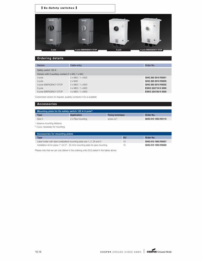
3-pole 3-pole EMERGENCY STOP 6-pole 6-pole EMERGENCY STOP
Ordering detai ls
Version Cable entry Order No.
Safety switch 125 A
Version with 2 auxiliary contact (1 x NO; 1 x NC)
3-pole 2 x M63 / 1 x M25 GHG 265 0010 R0001
4-pole 2 x M40 GHG 265 0010 R0005
3-pole EMERGENCY STOP 2 x M63 / 1 x M25 GHG 265 0010 R0002
6-pole 4 x M63 / 1 x M25 EXKO 224716 K 0000
6-pole EMERGENCY STOP 4 x M63 / 1 x M25 EXKO 224726 K 0000
Customized version on request, auxiliary contacts in Ex ia available
Accessories
Mounting plate for Ex-safety switch 125 A 3-pole2)
Type Application Fixing technique Order No.
Size 3 2 x Pipe mounting screw-on1) GHG 610 1953 R0110
1) observe mounting distance
2) 2 pcs. necessary for mounting
Accessories for mounting plates
Type OU Order No.
Label holder with label (unlabelled) mounting plate size 1, 2, 2A and 3 10 GHG 610 1953 R0057
Installation kit for pipes 1" (of 27 - 30 mm) mounting plate for pipe mounting 10 GHG 610 1953 R0020
Please note that we can only deliver in the ordering units (OU) stated in the tables above

C O O P E R C R O U S E - H I N D S G M B H 10.17
Dim
en
sio
ns
in
mm
Dimension drawing
3/4-pole
6-pole X = fixing dimensions
X 247
271
X 520
544
275211
11 Ø 12
Ø 7
530X500450
8
X540
655
35
335
I Ex-Safety switches I
6-pole EMERGENCY STOP 6-pole 3-pole EMERGENCY STOP 3-pole
1
2
3
4
5
6
7
8
9
10
11
12
10.18 C O O P E R C R O U S E - H I N D S G M B H
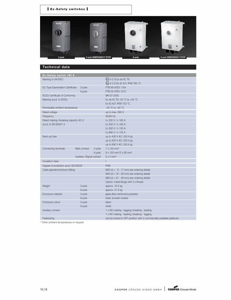
I Ex-Safety switches I
3-pole 3-pole EMERGENCY STOP 6-pole 6-pole EMERGENCY STOP
Technical data
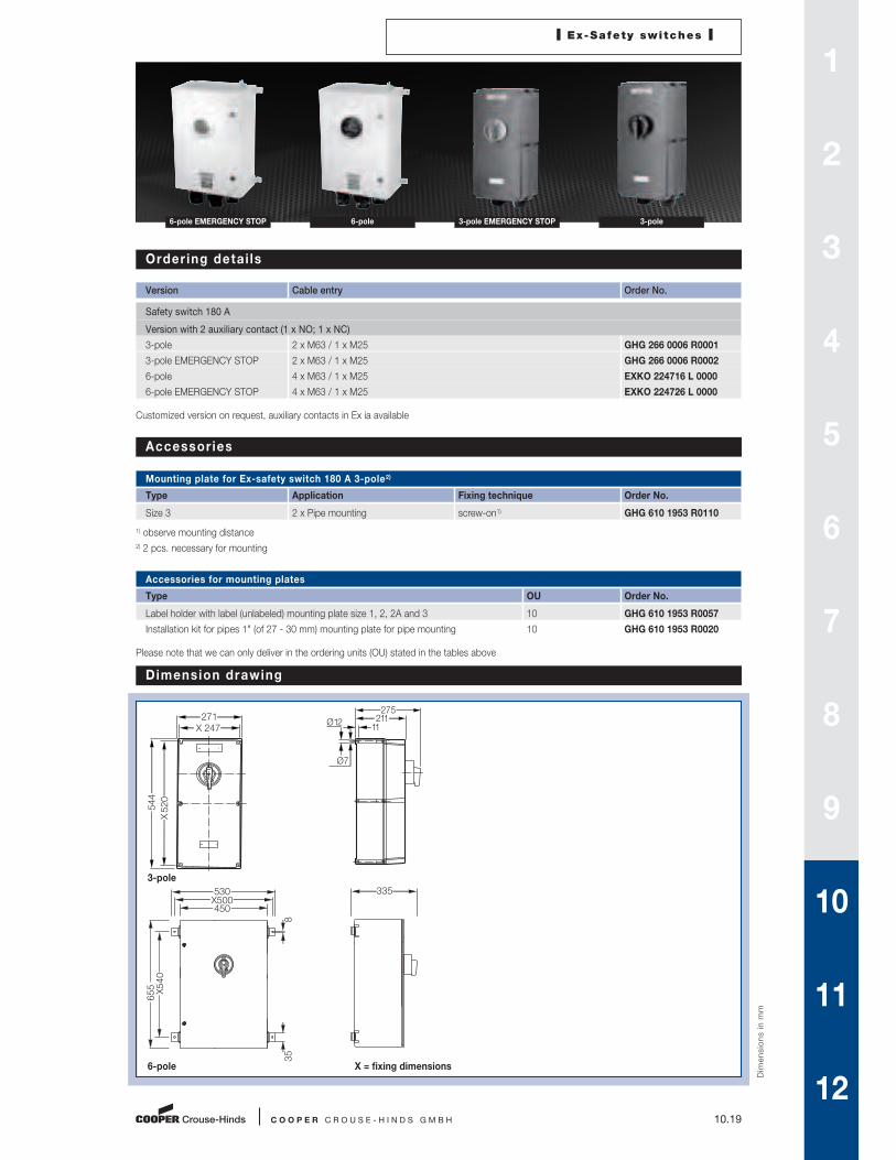
Ex-Safety switch 180 A
Marking to 94/9/EC II 2 G Ex de IIC T6
II 2 D Ex tD A21 IP66 T80 °C
EC-Type Examination Certificate 3-pole PTB 99 ATEX 1164
6-pole PTB 00 ATEX 1073
IECEx Certificate of Conformity BKI 07.0005
Marking accd. to IECEx Ex de IIC T6 –55 °C to +45 °C
Ex tD A21 IP66 T53 °C
Permissible ambient temperature –20 °C to +40 °C
Rated voltage up to max. 690 V
Frequency 50/60 Hz
Rated making-/breaking capacity AC-3 Ue 230 V / Ie 180 A
accd. to EN 60947-3 Ue 400 V / Ie 180 A
Ue 500 V / Ie 150 A
Ue 690 V / Ie 125 A
Back-up fuse up to 400 V AC: 250 A gL
up to 500 V AC: 250 A gL
up to 690 V AC: 200 A gL
Connecting terminals Main contact 3-pole 1 x 120 mm2
6-pole 6 x 150 mm2/2 x 95 mm2
Auxiliary-/Signal contact 2 x 4 mm2
Insulation class I
Degree of protection accd. EN 60529 IP66
Cable glands/enclosure drilling M25 (d = 8 - 17 mm) see ordering details
M40 (d = 16 - 28 mm) see ordering details
M63 (d = 27 - 48 mm) see ordering details
Option: metal flange with 2 x thread
Weight 3-pole approx. 16.5 kg
6-pole approx. 31,5 kg
Enclosure material 3-pole glass-fibre reinforced polyester
6-pole steel, powder-coated
Enclosure colour 3-pole black
6-pole white
Auxiliary contact 1 x NO making - lagging; breaking - leading
1 x NC making - leading; breaking - lagging
Padlocking can be locked in OFF position with 3 commercially available padlocks
1) Other ambient temperatures on request
I Ex-Safety switches I
C O O P E R C R O U S E - H I N D S G M B H 10.19
6-pole EMERGENCY STOP 6-pole 3-pole EMERGENCY STOP 3-pole
Ordering detai ls
Version Cable entry Order No.
Safety switch 180 A
Version with 2 auxiliary contact (1 x NO; 1 x NC)
3-pole 2 x M63 / 1 x M25 GHG 266 0006 R0001
3-pole EMERGENCY STOP 2 x M63 / 1 x M25 GHG 266 0006 R0002
6-pole 4 x M63 / 1 x M25 EXKO 224716 L 0000
6-pole EMERGENCY STOP 4 x M63 / 1 x M25 EXKO 224726 L 0000
Customized version on request, auxiliary contacts in Ex ia available
Accessories
Mounting plate for Ex-safety switch 180 A 3-pole2)
Type Application Fixing technique Order No.
Size 3 2 x Pipe mounting screw-on1) GHG 610 1953 R0110
1) observe mounting distance
2) 2 pcs. necessary for mounting
Accessories for mounting plates
Type OU Order No.
Label holder with label (unlabeled) mounting plate size 1, 2, 2A and 3 10 GHG 610 1953 R0057
Installation kit for pipes 1" (of 27 - 30 mm) mounting plate for pipe mounting 10 GHG 610 1953 R0020
Please note that we can only deliver in the ordering units (OU) stated in the tables above
Dim
en
sio
ns
in
mm
Dimension drawing
3-pole
6-pole X = fixing dimensions
X 247
271
X 520
544
275211
11 Ø 12
Ø 7
530X500450
8
X540
655
35
335
1
2
3
4
5
6
7
8
9
10
11
12

10.20 C O O P E R C R O U S E - H I N D S G M B H
I Ex-Safety switches I
3-pole 3-pole EMERGENCY STOP 6-pole 6-pole EMERGENCY STOP
Technical data
Ex-Safety switch 210 A
Marking to 94/9/EC II 2 G Ex de IIC T6, T5 or T41) / II 2 D IP66 T80 °C/T95 °C
EC-Type Examination Certificate PTB 99 ATEX 1057
IECEx Certificate of Conformity BKI 06.0006
Marking accd. to IECEx Ex de ia/ib [ia/ib] IIC T6, T5 or T4
Ex tD A21 IP66 T80 °C, T95 °C or T130 °C
Permissible ambient temperature –20 °C to +40 °C
Rated voltage up to max. 690 V
Rated current max. 210 A
Frequency 50/60 Hz
Rated making-/breaking capacity AC-3 Ue 230 V / Ie 210 A
accd. to EN 60947-3 Ue 400 V / Ie 210 A
Ue 500 V / Ie 210 A
Ue 690 V / Ie 210 A
Back-up fuse up to 400 V AC: 250 A gL
up to 500 V AC: 250 A gL
up to 690 V AC: 200 A gL
Connecting terminals Main contact 3-pole 3 x 150 mm2/95 mm2
6-pole 6 x 150 mm2/2 x 95 mm2
Auxiliary-/Signal contact 2 x 4 mm2
Insulation class I
Degree of protection accd. EN 60529 IP54 (IP65 optional)
Cable glands/enclosure drilling M25 (d = 8 - 17 mm) see ordering details
M63 (d = 27 - 48 mm) see ordering details
Weight 3-pole approx. 41.5 kg
6-pole approx. 84,5 kg
Enclosure material aluminium, powder-coated polyester
connection box steel, powder-coated
Colour Enclosure grey (RAL 7032)
Cover dark grey (RAL 7022)
Auxiliary contact 1 x NO making - lagging; breaking - leading
1 x NC making - leading; breaking - lagging
Padlocking can be locked in OFF position with 3 commercially available padlocks
1) Also available with Explosion Group IIB

I Ex-Safety switches I
C O O P E R C R O U S E - H I N D S G M B H 10.21
6-pole EMERGENCY STOP 6-pole 3-pole EMERGENCY STOP 3-pole
Ordering detai ls
Version Cable entry Order No.
Safety switch 210 A 3-pole
Version with 2 auxiliary contact (1 x NO; 1 x NC)
3-pole 2 x M63 / 1 x M25 EXKO 731713 S0001
3-pole EMERGENCY STOP 2 x M63 / 1 x M25 EXKO 731723 S0001
Safety switch 210 A 6-pole
Version with 2 auxiliary contact (1 x NO; 1 x NC)
6-pole 4 x M63 / 1 x M25 EXKO 731716 S0001
6-pole EMERGENCY STOP 4 x M63 / 1 x M25 EXKO 731726 S0001
Customized version on request, auxiliary contacts in Ex ia available
Dim
en
sio
ns
in
mm
Dimension drawing
3-pole
6-pole X = fixing dimensions
14
46
639
X 256
326320
X 295
329
14
971
156
X 365
435430
X 405
329
1
2
3
4
5
6
7
8
9
10
11
12

10.22 C O O P E R C R O U S E - H I N D S G M B H
I Ex-Safety switches I
3-pole 3-pole EMERGENCY STOP 6-pole 6-pole EMERGENCY STOP
Technical data
Ex-Safety switch 250 A
Marking to 94/9/EC II 2 G Ex de IIC T6, T5 or T41) / II 2 D IP66 T80 °C/T95 °C
EC-Type Examination Certificate PTB 99 ATEX 1057
IECEx Certificate of Conformity BKI 06.0006
Marking accd. to IECEx Ex de ia/ib [ia/ib] IIC T6, T5 or T4
Ex tD A21 IP66 T80 °C, T95 °C or T130 °C
Permissible ambient temperature –20 °C to +40 °C2)
Rated voltage up to max. 690 V
Rated current max. 250 A
Frequency 50/60 Hz
Rated making-/breaking capacity AC-3 Ue 230 V / Ie 250 A
accd. to EN 60947-3 Ue 400 V / Ie 250 A
Ue 500 V / Ie 250 A
Ue 690 V / Ie 250 A
Back-up fuse up to 400 V AC: 250 A gL
up to 500 V AC: 250 A gL
up to 690 V AC: 200 A gL
Connecting terminals Main contact 3-pole 3 x 150 mm2/95 mm2
6-pole 6 x 150 mm2/2 x 95 mm2
Auxiliary-/Signal contact 2 x 4 mm2
Insulation class I
Degree of protection accd. EN 60529 IP54 (IP65 optional)
Cable glands/enclosure drilling M25 (d = 8 - 17 mm) see ordering details
M63 (d = 27 - 48 mm) see ordering details
Weight 3-pole approx. 41.5 kg
6-pole approx. 84,5 kg
Enclosure material aluminium, powder-coated polyester
connection box steel, powder-coated
Colour Enclosure grey (RAL 7032)
Cover dark grey (RAL 7022)
Auxiliary contact 1 x NO making - lagging; breaking - leading
1 x NC making - leading; breaking - lagging
Padlocking can be locked in OFF position with 3 commercially available padlocks
1) Also available with Explosion Group IIB
2) Other ambient temperatures on request

I Ex-Safety switches I
C O O P E R C R O U S E - H I N D S G M B H 10.23
6-pole EMERGENCY STOP 6-pole 3-pole EMERGENCY STOP 3-pole
Ordering detai ls
Version Cable entry Order No.
Safety switch 250 A 3-pole
Version with 2 auxiliary contact (1 x NO; 1 x NC)
3-pole 2 x M63 / 1 x M25 EXKO 731713 T0001
3-pole EMERGENCY STOP 2 x M63 / 1 x M25 EXKO 731723 T0001
Safety switch 250 A 6-pole
Version with 2 auxiliary contact (1 x NO; 1 x NC)
6-pole 4 x M63 / 1 x M25 EXKO 731716 T0001
6-pole EMERGENCY STOP 4 x M63 / 1 x M25 EXKO 731726 T0001
Customized version on request, auxiliary contacts in Ex ia available
Dim
en
sio
ns
in
mm
Dimension drawing
3-pole
6-pole X = fixing dimensions
329
325320
X 295
945
46
X 255
14
14
1275
156
X 365
612
435430 329X 405
1
2
3
4
5
6
7
8
9
10
11
12

10.24 C O O P E R C R O U S E - H I N D S G M B H
I Ex-Safety switches I
3-pole 3-pole EMERGENCY STOP
Technical data
Ex-Safety switch 400 A
Marking to 94/9/EC II 2 G Ex de IIC T6, T5 or T41) / II 2 D IP66 T80 °C/T95 °C
EC-Type Examination Certificate PTB 99 ATEX 1057
IECEx Certificate of Conformity BKI 06.0006
Marking accd. to IECEx Ex de ia/ib [ia/ib] IIC T6, T5 or T4
Ex tD A21 IP66 T80 °C, T95 °C or T130 °C
Permissible ambient temperature –20 °C to +40 °C2)
Rated voltage up to max. 690 V
Rated current max. 400 A
Frequency 50/60 Hz
Rated making-/breaking capacity AC-3 Ue 230 V / Ie 400 A
accd. to EN 60947-3 Ue 400 V / Ie 400 A
Ue 500 V / Ie 400 A
Ue 690 V / Ie 400 A
Back-up fuse up to 400 V AC: 500 A gL
up to 500 V AC: 500 A gL
up to 690 V AC: 500 A gL
Connecting terminals Main contact 6 x 150 mm2/2 x 95 mm2
Auxiliary-/Signal contact 2 x 4 mm2
Insulation class I
Degree of protection accd. EN 60529 IP54 (IP65 optional)
Cable glands/enclosure drilling M25 (d = 8 - 17 mm) see ordering details
M63 (d = 27 - 48 mm) see ordering details
Weight approx. 64.5 kg
Enclosure material aluminium, powder-coated polyester
connection box steel, powder-coated
Colour Enclosure grey (RAL 7032)
Cover dark grey (RAL 7022)
Auxiliary contact 1 x NO making - lagging; breaking - leading
1 x NC making - leading; breaking - lagging
Padlocking can be locked in OFF position with 3 commercially available padlocks
1) Also available with Explosion Group IIB
2) Other ambient temperatures on request

I Ex-Safety switches I
C O O P E R C R O U S E - H I N D S G M B H 10.25
3-pole EMERGENCY STOP 3-pole
Ordering detai ls
Version Cable entry Order No.
Safety switch 400 A 3-pole
Version with 2 auxiliary contact (1 x NO; 1 x NC)
3-pole 4 x M63 / 1 x M25 EXKO 731713 U0001
3-pole EMERGENCY STOP 4 x M63 / 1 x M25 EXKO 731723 U0001
Customized version on request, auxiliary contacts in Ex ia available
Dim
en
sio
ns
in
mm
Dimension drawing
3-pole X = fixing dimensions
14
1056
X 365
46
600
430329X405
1
2
3
4
5
6
7
8
9
10
11
12

10.26 C O O P E R C R O U S E - H I N D S G M B H
I Ex-Safety switches I
3-pole
Technical data
Ex-Safety switch 630 A
Marking to 94/9/EC II 2 G Ex de IIC T6, T5 or T41) / II 2 D IP66 T80 °C/T95 °C
EC-Type Examination Certificate PTB 99 ATEX 1057
IECEx Certificate of Conformity BKI 06.0006
Marking accd. to IECEx Ex de ia/ib [ia/ib] IIC T6, T5 or T4
Ex tD A21 IP66 T80 °C, T95 °C or T130 °C
Permissible ambient temperature –20 °C to +40 °C2)
Rated voltage up to max. 690 V
Rated current max. 630 A
Frequency 50/60 Hz
Rated making-/breaking capacity AC-3 Ue 230 V / Ie 630 A
accd. to EN 60947-3 Ue 400 V / Ie 630 A
Ue 500 V / Ie 630 A
Ue 690 V / Ie 630 A
Back-up fuse up to 400 V AC: 800 A gL
up to 500 V AC: 800 A gL
up to 690 V AC: 800 A gL
Connecting terminals Main contact 6 x 240 mm2/2 x 120 mm2
Auxiliary/Signal contact 2 x 4 mm2
Insulation class I
Degree of protection accd. EN 60529 IP54 (IP65 optional)
Cable glands/enclosure drilling M25 (d = 8 - 17 mm) see ordering details
M80 (d = 62 - 68 mm) see ordering details
Weight approx. 245 kg
Enclosure material steel, powder-coated polyester
connection box steel, powder-coated
Colour Enclosure grey (RAL 7032)
Cover dark grey (RAL 7022)
Auxiliary contact 1 x NO making - lagging; breaking - leading
1 x NC making - leading; breaking - lagging
Padlocking can be locked in OFF position with 3 commercially available padlocks
1) Also available with Explosion Group IIB
2) Other ambient temperatures on request

I Ex-Safety switches I
C O O P E R C R O U S E - H I N D S G M B H 10.27
3-pole
Ordering detai ls
Version Cable entry Order No.
Safety switch 630 A 3-pole
Version with 2 auxiliary contact (1 x NO; 1 x NC)
3-pole 4 x M80 / 1 x M25 EXKO 731713 V0001
3-pole EMERGENCY STOP 4 x M80 / 1 x M25 EXKO 731723 V0001
Customized version on request, auxiliary contacts in Ex ia available
Dim
en
sio
ns
in
mm
Dimension drawing
3-pole X = fixing dimensions
1
2
3
4
5
6
7
8
9
10
11
12
650
M20 x 2
X 600
655510
X 505
1062
73
130
10.28 C O O P E R C R O U S E - H I N D S G M B H
I Ex-Safety switches I
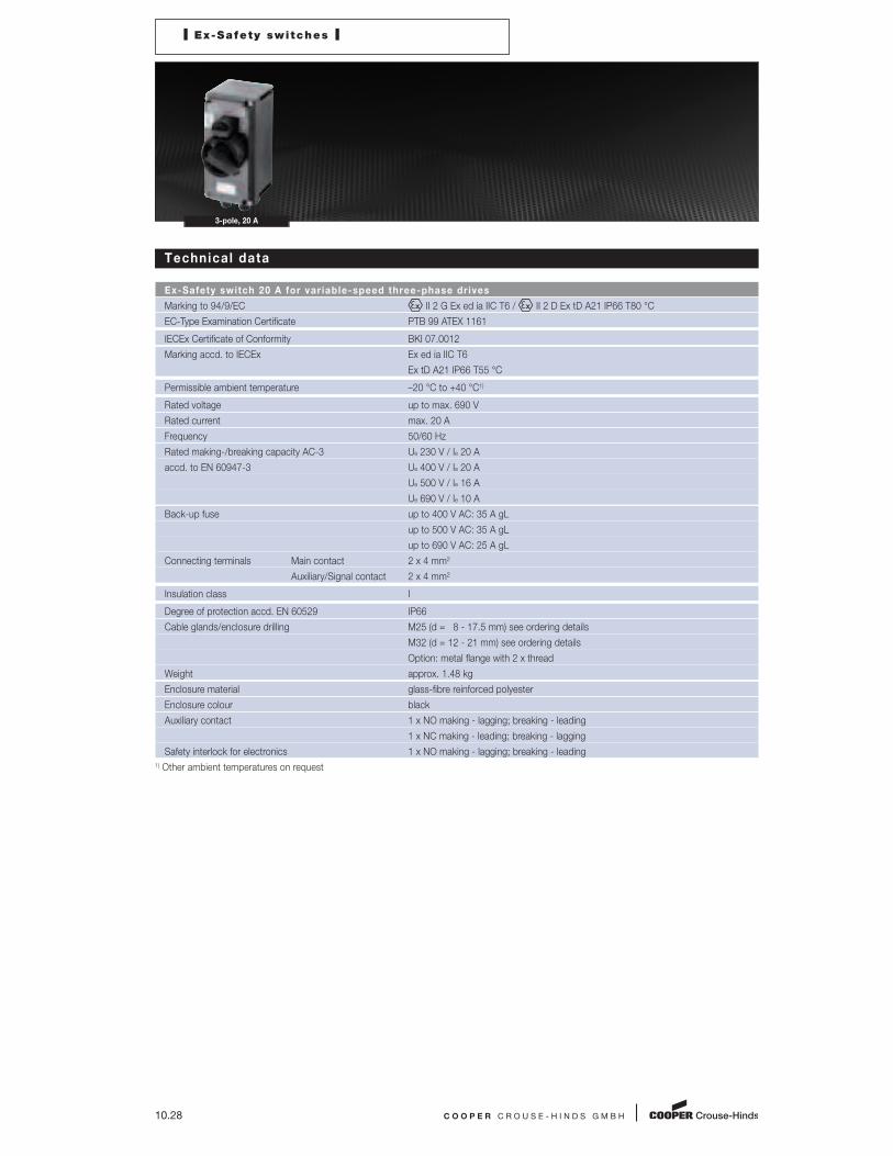
3-pole, 20 A
Technical data
Ex-Safety switch 20 A for var iable-speed three-phase dr ives
Marking to 94/9/EC II 2 G Ex ed ia IIC T6 / II 2 D Ex tD A21 IP66 T80 °C
EC-Type Examination Certificate PTB 99 ATEX 1161
IECEx Certificate of Conformity BKI 07.0012
Marking accd. to IECEx Ex ed ia IIC T6
Ex tD A21 IP66 T55 °C
Permissible ambient temperature –20 °C to +40 °C1)
Rated voltage up to max. 690 V
Rated current max. 20 A
Frequency 50/60 Hz
Rated making-/breaking capacity AC-3 Ue 230 V / Ie 20 A
accd. to EN 60947-3 Ue 400 V / Ie 20 A
Ue 500 V / Ie 16 A
Ue 690 V / Ie 10 A
Back-up fuse up to 400 V AC: 35 A gL
up to 500 V AC: 35 A gL
up to 690 V AC: 25 A gL
Connecting terminals Main contact 2 x 4 mm2
Auxiliary/Signal contact 2 x 4 mm2
Insulation class I
Degree of protection accd. EN 60529 IP66
Cable glands/enclosure drilling M25 (d = 8 - 17.5 mm) see ordering details
M32 (d = 12 - 21 mm) see ordering details
Option: metal flange with 2 x thread
Weight approx. 1.48 kg
Enclosure material glass-fibre reinforced polyester
Enclosure colour black
Auxiliary contact 1 x NO making - lagging; breaking - leading
1 x NC making - leading; breaking - lagging
Safety interlock for electronics 1 x NO making - lagging; breaking - leading
1) Other ambient temperatures on request

I Ex-Safety switches I
C O O P E R C R O U S E - H I N D S G M B H 10.29
3-pole, 20 A
Ordering detai ls
Version Cable entry Order No.
Safety switch 20 A
Version with 2 auxiliary contact (1 x NO; 1 x NC), 1 x safety interlock for electronics (1 x NO)
3-pole 2 x M32 / 2 x M25 GHG 262 0014 R0001
Customized version on request
Accessories
Mounting plate for Ex-safety switch 20 A variable-speed three-phase drives
Type Application Fixing technique Order No.
Size 3 Wall mounting screw-on GHG 610 1953 R0118
Size 3 Pipe mounting screw-on GHG 610 1953 R0110
Size 3 Trellis mounting screw-on GHG 610 1953 R0118
Accessories for mounting plates
Type OU Order No.
Label holder with label (unlabelled) mounting plate size 1, 2, 2A and 3 10 GHG 610 1953 R0057
Installation kit for pipes 1" (of 27 - 30 mm) mounting plate for pipe mounting 10 GHG 610 1953 R0020
Accessories canopies for mounting plates
Type Application OU Order No.
Size 3 for pipe mounting plate size 3 vertical 1 GHG 610 1955 R0104
Size 3A for wall/trellis mounting plate size 3 vertical 1 GHG 610 1955 R0105
Size 3 for pipe mounting plate size 3 horizontal 1 GHG 610 1955 R0106
Please note that we can only deliver in the ordering units (OU) stated in the tables above
Dim
en
sio
ns
in
mm
Dimension drawing
3-pole X = fixing dimensions
X 110.5134.5
X 247
271
200 135 11
Ø 12
Ø 7
1
2
3
4
5
6
7
8
9
10
11
12

10.30 C O O P E R C R O U S E - H I N D S G M B H
I Ex-Safety switches I
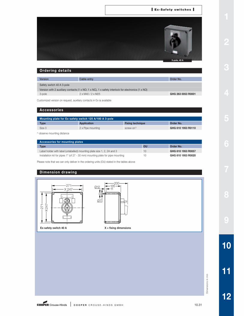
3-pole, 40 A
Technical data
Ex-Safety switch 40 A for var iable-speed three-phase dr ives
Marking to 94/9/EC II 2 G Ex ed ia IIC T6 / II 2 D Ex tD A21 IP66 T80 °C
EC-Type Examination Certificate PTB 99 ATEX 1161
IECEx Certificate of Conformity BKI 07.0012
Marking accd. to IECEx Ex ed ia IIC T6
Ex tD A21 IP66 T53 °C
Permissible ambient temperature –20 °C to +40 °C1)
Rated voltage up to max. 690 V
Rated current max. 40 A
Frequency 50/60 Hz
Rated making-/breaking capacity AC-3 Ue 230 V / Ie 40 A
accd. to EN 60947-3 Ue 400 V / Ie 40 A
Ue 500 V / Ie 40 A
Ue 690 V / Ie 32 A
Back-up fuse up to 400 V AC: 80 A gL
up to 500 V AC: 80 A gL
up to 690 V AC: 63 A gL
Connecting terminals Main contact 2 x 16 mm2
Auxiliary-/Signal contact 2 x 4 mm2
Insulation class I
Degree of protection accd. EN 60529 IP66
Cable glands/enclosure drilling M25 (d = 8 - 17.5 mm) see ordering details
M40 (d = 17 - 28 mm) see ordering details
M50 (d = 22 - 35 mm) see ordering details
Option: metal flange with 2 x thread
Weight approx. 4.3 kg
Enclosure material glass-fibre reinforced polyester
Enclosure colour black
Auxiliary contact 1 x NO making - lagging; breaking - leading
1 x NC making - leading; breaking - lagging
Safety interlock for electronics 1 x NO making - lagging; breaking - leading
Padlocking can be locked in OFF position with 3 commercially available padlocks
1) Other ambient temperatures on request
I Ex-Safety switches I
C O O P E R C R O U S E - H I N D S G M B H 10.31
3-pole, 40 A
Ordering detai ls
Version Cable entry Order No.
Safety switch 40 A 3-pole
Version with 2 auxiliary contacts (1 x NO; 1 x NC), 1 x safety interlock for electronics (1 x NO)
3-pole 2 x M40 / 2 x M25 GHG 263 0053 R0001
Customized version on request, auxiliary contacts in Ex ia available
Dim
en
sio
ns
in
mm
Dimension drawing
Ex-safety switch 40 A X = fixing dimensions
X 247
271
X 247
271
200 135 11
Ø 12
Ø 7
Accessories
Mounting plate for Ex-safety switch 125 A/180 A 3-pole
Type Application Fixing technique Order No.
Size 3 2 x Pipe mounting screw-on1) GHG 610 1953 R0110
1) observe mounting distance
Accessories for mounting plates
Type OU Order No.
Label holder with label (unlabelled) mounting plate size 1, 2, 2A and 3 10 GHG 610 1953 R0057
Installation kit for pipes 1" (of 27 - 30 mm) mounting plate for pipe mounting 10 GHG 610 1953 R0020
Please note that we can only deliver in the ordering units (OU) stated in the tables above
1
2
3
4
5
6
7
8
9
10
11
12

10.32 C O O P E R C R O U S E - H I N D S G M B H
I Ex-Safety switches I
3-pole, 80 A
Technical data
Ex-Safety switch 80 A for var iable-speed three-phase dr ives
Marking to 94/9/EC II 2 G Ex de IIC T6 / II 2 D A21 IP66 T80 °C
EC-Type Examination Certificate PTB 00 ATEX 1091
IECEx Certificate of Conformity BKI 07.0010
Marking accd. to IECEx Ex ed ia II T6
Ex tD A21 IP66 T53 °C
Permissible ambient temperature –20 °C to +40 °C
Rated voltage up to max. 690 V
Rated current max. 80 A
Frequency 50/60 Hz
Rated making-/breaking capacity AC-3 Ue 230 V / Ie 80 A
accd. to EN 60947-3 Ue 400 V / Ie 80 A
Ue 500 V / Ie 80 A
Ue 690 V / Ie 63 A
Back-up fuse up to 400 V AC: 160 A gL
up to 500 V AC: 160 A gL
up to 690 V AC: 160 A gL
Connecting terminals Main contact 2 x 25 mm2
Auxiliary-/Signal contact 2 x 4 mm2
Insulation class I
Degree of protection accd. EN 60529 IP66
Cable glands/enclosure drilling M25 (d = 8 - 17.5 mm) see ordering details
M40 (d = 17 - 28 mm) see ordering details
M50 (d = 22 - 35 mm) see ordering details
Option: metal flange with 2 x thread
Weight approx. 7.25 kg
Enclosure material glass-fibre reinforced polyester
Enclosure colour black
Auxiliary contact 1 x NO making - lagging; breaking - leading
1 x NC making - leading; breaking - lagging
Safety interlock for electronics 1 x NO making - lagging; breaking - leading
Padlocking can be locked in OFF position with 3 commercially available padlocks
1) Other ambient temperatures on request

I Ex-Safety switches I
C O O P E R C R O U S E - H I N D S G M B H 10.33
3-pole, 80 A
Ordering detai ls
Version Cable entry Order No.
Safety switch 80 A 3-pole
Version with 2 auxiliary contacts (1 x NO; 1 x NC), 1 x safety interlock for electronics (1 x NO)
3-pole 2 x M50 / 2 x M25 GHG 264 0024 R0001
Customized version on request, auxiliary contacts in Ex ia available
Dim
en
sio
ns
in
mm
Dimension drawing
Ex-safety switch 80 A X = fixing dimensions
X 247
271
X 247
271
27511
Ø 12
Ø 7
Accessories
Mounting plate for Ex-safety switch 80 A variable-speed three-phase drives
Type Application Fixing technique Order No.
Size 3 2 x Pipe mounting screw-on1) GHG 610 1953 R0110
1) observe mounting distance
Accessories for mounting plates
Type OU Order No.
Label holder with label (unlabelled) mounting plate size 1, 2, 2A and 3 10 GHG 610 1953 R0057
Installation kit for pipes 1" (of 27 - 30 mm) mounting plate for pipe mounting 10 GHG 610 1953 R0020
Please note that we can only deliver in the ordering units (OU) stated in the tables above
1
2
3
4
5
6
7
8
9
10
11
12
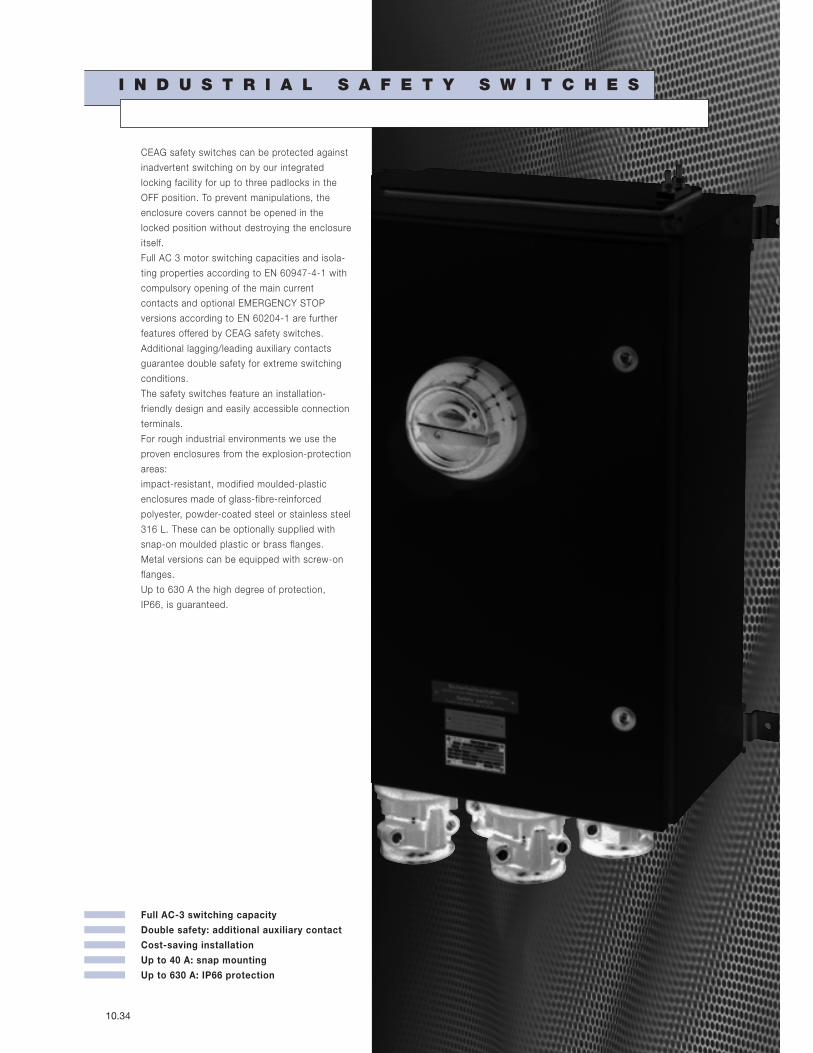
Full AC-3 switching capacity
Double safety: additional auxiliary contact
Cost-saving installation
Up to 40 A: snap mounting
Up to 630 A: IP66 protection
10.34
I N D U S T R I A L S A F E T Y S W I T C H E S
CEAG safety switches can be protected against
inadvertent switching on by our integrated
locking facility for up to three padlocks in the
OFF position. To prevent manipulations, the
enclosure covers cannot be opened in the
locked position without destroying the enclosure
itself.
Full AC 3 motor switching capacities and isola-
ting properties according to EN 60947-4-1 with
compulsory opening of the main current
contacts and optional EMERGENCY STOP
versions according to EN 60204-1 are further
features offered by CEAG safety switches.
Additional lagging/leading auxiliary contacts
guarantee double safety for extreme switching
conditions.
The safety switches feature an installation-
friendly design and easily accessible connection
terminals.
For rough industrial environments we use the
proven enclosures from the explosion-protection
areas:
impact-resistant, modified moulded-plastic
enclosures made of glass-fibre-reinforced
polyester, powder-coated steel or stainless steel
316 L. These can be optionally supplied with
snap-on moulded plastic or brass flanges.
Metal versions can be equipped with screw-on
flanges.
Up to 630 A the high degree of protection,
IP66, is guaranteed.

I Industr ia l safety switches I
C O O P E R C R O U S E - H I N D S G M B H 10.35
3-pole EMERGENCY STOP 3-pole
Technical data
Industr ia l-Safety switch 10 A
Permissible ambient temperature –20 °C to +40 °C
Rated voltage up to max. 500 V
Rated current max. 10 A
Frequency 50/60 Hz
Rated making-/breaking capacity AC-3 Ue 230 V / Ie 10 A
accd. to EN 60947-3 Ue 400 V / Ie 10 A
Ue 500 V / Ie 10 A
Back-up fuse up to 400 V AC: 20 A gL
up to 500 V AC: 16 A gL
Connecting terminals Main contact 2 x 1.5 - 2.5 mm2
Auxiliary-/Signal contact 2 x 0.5 - 2.5 mm2
Insulation class I
Degree of protection accd. EN 60529 IP66
Cable glands/enclosure drilling M20 (d = 5 - 13 mm) see ordering details
M25 (d = 8 - 17 mm) see ordering details
Weight 0.55 kg
Enclosure material impact resistant polyamide
Enclosure colour black
Auxiliary contact 1 x NO making - lagging; breaking - leading
Padlocking can be locked in OFF position with 3 commercially available padlocks
1
2
3
4
5
6
7
8
9
10
11
12

10.36 C O O P E R C R O U S E - H I N D S G M B H
I Industr ia l safety switches I
3-pole 3-pole EMERGENCY STOP
Ordering detai ls
Version Cable entry Order No.
Industrial-Safety switch 10 A
3-pole 2 x M25 / 1 x M20 GHG 981 0014 R0011
3-pole EMERGENCY STOP 2 x M25 / 1 x M20 GHG 981 0014 R0012
Customized version on request
Accessories
Mounting plate for industrial-safety switch 10 A 3-pole
Type Application Fixing technique Order No.
Size 1 Wall mounting screw-on GHG 610 1953 R0101
Size 1 Pipe mounting screw-on GHG 610 1953 R0102
Size 1 Trellis mounting screw-on GHG 610 1953 R0103
Accessories for mounting plates
Type OU Order No.
Label holder with label (unlabelled) mounting plate size 1, 2, 2A and 3 10 GHG 610 1953 R0057
Installation kit for pipes 1" (of 27 - 30 mm) mounting plate for pipe mounting 10 GHG 610 1953 R0020
Accessories canopies for mounting plates
Type Application OU Order No.
Size 1 mounting plate size 1 1 GHG 610 1955 R0101
Please note that we can only deliver in the ordering units (OU) stated in the tables above
Dim
en
sio
ns
in
mm
Dimension drawing
3-pole X = fixing dimensions
102
X61.5
X68.5
84
80
112
Ø 5.5
Ø 8.5
I Industr ia l safety switches I
C O O P E R C R O U S E - H I N D S G M B H 10.37
6-pole EMERGENCY STOP 6-pole 3-pole EMERGENCY STOP 3-pole
Technical data
Industr ia l-Safety switch 25 A
Permissible ambient temperature –20 °C to +40 °C
Rated voltage up to max. 690 V
Rated current max. 25 A
Frequency 50/60 Hz
Rated making-/breaking capacity AC-3 Ue 230 V / Ie 20 A
accd. to EN 60947-3 Ue 400 V / Ie 20 A
Ue 500 V / Ie 16 A
Ue 690 V / Ie 10 A
Back-up fuse up to 400 V AC: 35 A gL
up to 500 V AC: 35 A gL
up to 690 V AC: 25 A gL
Connecting terminals Main contact 2 x 4 mm2
Auxiliary-/Signal contact 2 x 0.5 - 2.5 mm2
Insulation class I
Degree of protection accd. EN 60529 IP66
Cable glands/enclosure drilling M25 (d = 8 - 17 mm) see ordering details
M32 (d = 12 - 21 mm) see ordering details
Option: metal flange with 2 x thread
Weight 3-pole approx. 1.48 kg
6-pole approx. 2.43 kg
Enclosure material glass-fibre reinforced polyester
Enclosure colour black
Auxiliary contact 1 x NO making - lagging; breaking - leading
1 x NC (only 6-pole version) making - leading; breaking - lagging
Padlocking can be locked in OFF position with 3 commercially available padlocks
1
2
3
4
5
6
7
8
9
10
11
12

10.38 C O O P E R C R O U S E - H I N D S G M B H
I Industr ia l safety switches I
3-pole 3-pole EMERGENCY STOP 6-pole 6-pole EMERGENCY STOP
Ordering detai ls
Version Cable entry Order No.
Industrial-Safety switch 25 A 3-pole
Version with 1 auxiliary contact (NO)
3-pole 2 x M32 / 1 x M25 GHG 981 0037 R0001
3-pole EMERGENCY STOP 2 x M32 / 1 x M25 GHG 981 0037 R0002
Industrial-Safety switch 25 A 6-pole
Version with 2 auxiliary contacts (1 x NO; 1 x NC)
6-pole 4 x M32 / 1 x M25 GHG 981 0038 R0001
6-pole EMERGENCY STOP 4 x M32 / 1 x M25 GHG 981 0038 R0002
Customized version on request
Accessories
Mounting plate for industrial-safety switch 25 A 3-pole
Type Application Fixing technique Order No.
Size 2 Wall mounting snap-on GHG 610 1953 R0104
Size 2 Pipe mounting snap-on GHG 610 1953 R0105
Size 2 Trellis mounting snap-on GHG 610 1953 R0106
Mounting plate for industrial-safety switch 25 A 6-pole
Type Application Fixing technique Order No.
Size 3 Wall mounting snap-on GHG 610 1953 R0118
Size 3 Pipe mounting snap-on GHG 610 1953 R0110
Size 3 Trellis mounting snap-on GHG 610 1953 R0118
Accessories for mounting plates
Type OU Order No.
Label holder with label (unlabelled) for mounting plates size 1, 2, 2A and 3 10 GHG 610 1953 R0057
Snap-on for CEAG apparatus with 5.5 mm and 11 mm mounting feet 1 set = 4 each 10 GHG 610 1953 R0041
Installation kit for pipes 1” (of 27 - 30 mm) for mounting plates for pipe mounting 10 GHG 610 1953 R0020
Accessories for canopies plates
Type Application OU Order No.
Size 2 for mounting plates size 2 1 GHG 610 1955 R0102
Size 2A for mounting plates size 2A 1 GHG 610 1955 R0103
Size 3 for pipe mounting plate size 3 vertical 1 GHG 610 1955 R0104
Size 3A for wall/trellis mounting plate size 3 vertical 1 GHG 610 1955 R0105
Size 3B for pipe mounting plate size 3 horizontal 1 GHG 610 1955 R0106
Please note that we can only deliver in the ordering units (OU) stated in the tables above
C O O P E R C R O U S E - H I N D S G M B H 10.39
Dim
en
sio
ns
in
mm
I Industr ia l safety switches I
6-pole EMERGENCY STOP 6-pole 3-pole EMERGENCY STOP 3-pole
Dimension drawing
3-pole
6-pole X = fixing dimensions
X150
X96110
170
129
7
13
X197
X123-126140
225
156
7
8
1
2
3
4
5
6
7
8
9
10
11
12
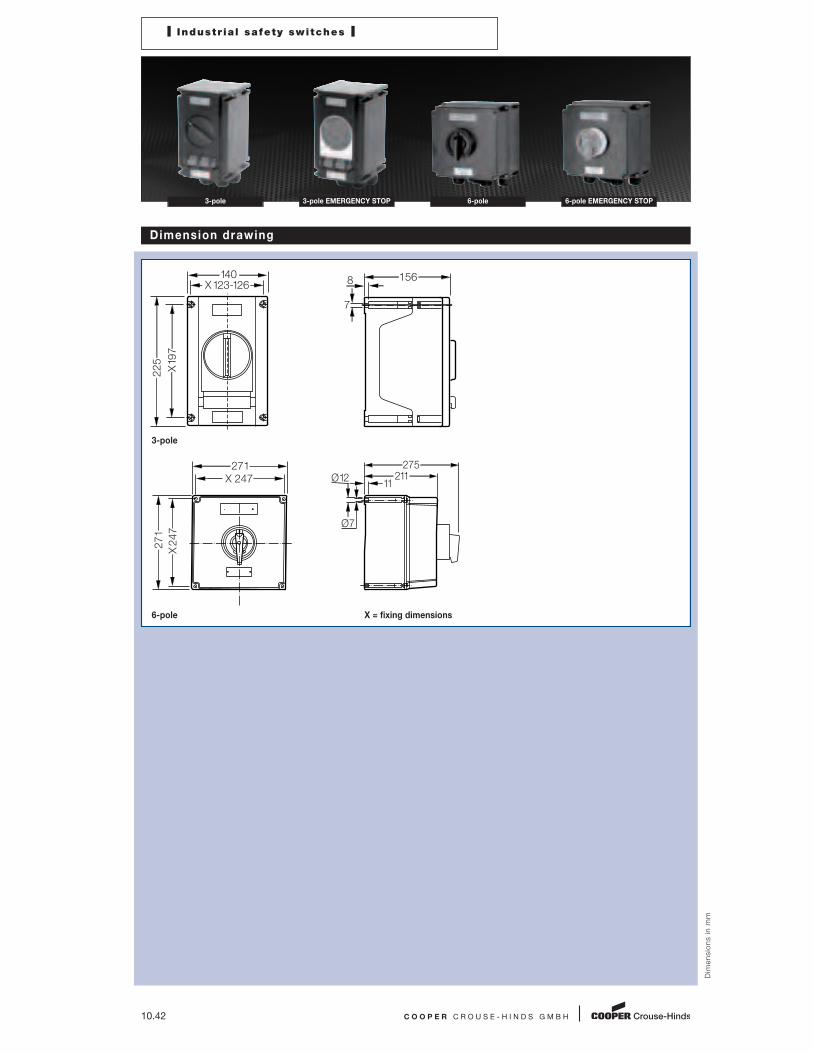
10.40 C O O P E R C R O U S E - H I N D S G M B H
I Industr ia l safety switches I
3-pole 3-pole EMERGENCY STOP 6-pole 6-pole EMERGENCY STOP
Technical data
Industr ia l-Safety switch 40 A
Permissible ambient temperature –20 °C to +40 °C
Rated voltage up to max. 690 V
Rated current max. 40 A
Frequency 50/60 Hz
Rated making-/breaking capacity AC-3 Ue 230 V / Ie 40 A
accd. to EN 60947-3 Ue 400 V / Ie 40 A
Ue 500 V / Ie 40 A
Ue 690 V / Ie 32 A
Back-up fuse up to 400 V AC: 80 A gL
up to 500 V AC: 80 A gL
up to 690 V AC: 63 A gL
Connecting terminals Main contact 2 x 16 mm2
Auxiliary-/Signal contact 2 x 4 mm2
Insulation class I
Degree of protection accd. EN 60529 IP66
Cable glands/enclosure drilling M25 (d = 8 - 17 mm) see ordering details
M40 (d = 16 - 28 mm) see ordering details
Option: metal flange on request
Weight 3-pole approx. 2.30 kg
6-pole approx. 6.50 kg
Enclosure material glass-fibre reinforced polyester
Enclosure colour black
Auxiliary contact 1 x NO making - lagging; breaking - leading
1 x NC making - leading; breaking - lagging
Padlocking can be locked in OFF position with 3 commercially available padlocks
I Industr ia l safety switches I
C O O P E R C R O U S E - H I N D S G M B H 10.41
6-pole EMERGENCY STOP 6-pole 3-pole EMERGENCY STOP 3-pole
Ordering detai ls
Version Cable entry Order No.
Industrial-Safety switch 40 A 3-pole
Version with 2 auxiliary contacts (1 x NO; 1 x NC)
3-pole 2 x M40 / 1 x M25 GHG 981 0039 R0001
3-pole EMERGENCY STOP 2 x M40 / 1 x M25 GHG 981 0039 R0002
Industrial-Safety switch 40 A 6-pole
Version with 2 auxiliary contacts (1 x NO; 1 x NC)
6-pole 4 x M40 / 1 x M25 GHG 981 0024 R0001
6-pole EMERGENCY STOP 4 x M40 / 1 x M25 GHG 981 0024 R0002
Customized version on request
Accessories
Mounting plate for industrial-safety switch 40 A 3-pole
Type Application Fixing technique Order No.
Size 3 Wall mounting snap-on GHG 610 1953 R0118
Size 3 Pipe mounting snap-on GHG 610 1953 R0110
Size 3 Trellis mounting snap-on GHG 610 1953 R0118
Mounting plate for industrial-safety switch 40 A 6-pole
Type Application Fixing technique Order No.
Size 3 2 x Pipe mounting screw-on1) GHG 610 1953 R0110
1) observe mounting distance
Accessories for mounting plates
Type OU Order No.
Label holder with label (unlabelled) for mounting plates size 1, 2, 2A and 3 10 GHG 610 1953 R0057
Snap-on for CEAG apparatus with 5.5 mm and 11 mm mounting feet 1 set = 4 each 10 GHG 610 1953 R0041
Installation kit for pipes 1” (of 27 - 30 mm) for mounting plates for pipe mounting 10 GHG 610 1953 R0020
Accessories for canopies plates
Type Application OU Order No.
Size 3 for pipe mounting plate size 3 vertical 1 GHG 610 1955 R0104
Size 3A for wall/trellis mounting plate size 3 vertical 1 GHG 610 1955 R0105
Size 3B for pipe mounting plate size 3 horizontal 1 GHG 610 1955 R0106
Please note that we can only deliver in the ordering units (OU) stated in the tables above
1
2
3
4
5
6
7
8
9
10
11
12
10.42 C O O P E R C R O U S E - H I N D S G M B H
Dim
en
sio
ns
in
mm
I Industr ia l safety switches I
3-pole 3-pole EMERGENCY STOP 6-pole 6-pole EMERGENCY STOP
Dimension drawing
3-pole
6-pole X = fixing dimensions
X197
X123-126140
225
156
7
8
X 247
271
X 247
271
275211
11 Ø 12
Ø 7

I Industr ia l safety switches I
C O O P E R C R O U S E - H I N D S G M B H 10.43
6-pole EMERGENCY STOP 6-pole 3-pole EMERGENCY STOP 3-pole
Technical data
Industr ia l-Safety switch 80 A
Permissible ambient temperature –20 °C to +40 °C
Rated voltage up to max. 690 V
Rated current max. 80 A
Frequency 50/60 Hz
Rated making-/breaking capacity AC-3 Ue 230 V / Ie 80 A
accd. to EN 60947-3 Ue 400 V / Ie 80 A
Ue 500 V / Ie 80 A
Ue 690 V / Ie 80 A
Back-up fuse up to 400 V AC: 160 A gL
up to 500 V AC: 160 A gL
up to 690 V AC: 125 A gL
Connecting terminals Main contact 2 x 25 mm2
Auxiliary-/Signal contact 2 x 4 mm2
Insulation class I
Degree of protection accd. EN 60529 IP66
Cable glands/enclosure drilling M25 (d = 8 - 17 mm) see ordering details
M50 (d = 21 - 35 mm) see ordering details
Option: metal flange with 2 x thread
Weight 3-pole approx. 6.50 kg
6-pole approx. 9.00 kg
Enclosure material glass-fibre reinforced polyester
Enclosure colour black
Auxiliary contact 1 x NO making - lagging; breaking - leading
1 x NC making - leading; breaking - lagging
Padlocking can be locked in OFF position with 3 commercially available padlocks
1
2
3
4
5
6
7
8
9
10
11
12

Dim
en
sio
ns
in
mm
10.44 C O O P E R C R O U S E - H I N D S G M B H
I Industr ia l safety switches I
3-pole 3-pole EMERGENCY STOP 6-pole 6-pole EMERGENCY STOP
Ordering detai ls
Version Cable entry Order No.
Industrial-Safety switch 80 A 3-pole
Version with 2 auxiliary contacts (1 x NO; 1 x NC)
3-pole 2 x M50 / 1 x M25 GHG 981 0025 R0001
3-pole EMERGENCY STOP 2 x M50 / 1 x M25 GHG 981 0025 R0002
Industrial-Safety switch 80 A 6-pole
Version with 2 auxiliary contacts (1 x NO; 1 x NC)
6-pole 4 x M50 / 1 x M25 GHG 981 0026 R0001
6-pole EMERGENCY STOP 4 x M50 / 1 x M25 GHG 981 0026 R0002
Customized version on request
Accessories
Mounting plate for industrial-safety switch
Type Application Fixing technique Order No.
Size 3 2 x Pipe mounting screw-on1) GHG 610 1953 R0110
1) observe mounting distance
Accessories for mounting plates
Type OU Order No.
Label holder with label (unlabelled) for mounting plates size 1, 2, 2A and 3 10 GHG 610 1953 R0057
Installation kit for pipes 1” (of 27 - 30 mm) for mounting plates for pipe mounting 10 GHG 610 1953 R0020
Please note that we can only deliver in the ordering units (OU) stated in the tables above
Dimension drawing
3-pole
6-pole X = fixing dimensions
X 247
271
X 247
271
275211
11 Ø 12
Ø 7
X 247
271
X 247
271
295211
11 Ø 12
Ø 7
I Industr ia l safety switches I
C O O P E R C R O U S E - H I N D S G M B H 10.45
6-pole EMERGENCY STOP 6-pole 3-pole EMERGENCY STOP 3-pole
Technical data
Industr ia l-Safety switch 100 A
Permissible ambient temperature –20 °C to +40 °C
Rated voltage up to max. 690 V
Rated current max. 100 A
Frequency 50/60 Hz
Rated making-/breaking capacity AC-3 Ue 230 V / Ie 100 A
accd. to EN 60947-3 Ue 400 V / Ie 100 A
Ue 500 V / Ie 100 A
Ue 690 V / Ie 100 A
Back-up fuse up to 400 V AC: 200 A gL
up to 500 V AC: 200 A gL
up to 690 V AC: 160 A gL
Connecting terminals Main contact 1 x 50/70 mm2
Auxiliary-/Signal contact 2 x 4 mm2
Insulation class I
Degree of protection accd. EN 60529 IP66
Cable glands/enclosure drilling M25 (d = 8 - 17 mm) see ordering details
M50 (d = 21 - 35 mm) see ordering details
Option: metal flange with 2 x thread
Weight 3-pole approx. 9.50 kg
6-pole approx. 16.00 kg
Enclosure material 3-pole glass-fibre reinforced polyester
6-pole steel, powder-coated
Enclosure colour black
Auxiliary contact 1 x NO making - lagging; breaking - leading
1 x NC making - leading; breaking - lagging
Padlocking can be locked in OFF position with 3 commercially available padlocks
1
2
3
4
5
6
7
8
9
10
11
12

10.46 C O O P E R C R O U S E - H I N D S G M B H
Ordering detai ls
Version Cable entry Order No.
Industrial-Safety switch 100 A 3-pole
Version with 4 auxiliary contacts (2 x NO; 2 x NC)
3-pole 2 x M50 / 1 x M25 GHG 981 0029 R0004
3-pole EMERGENCY STOP 2 x M50 / 1 x M25 GHG 981 0029 R0005
Industrial-Safety switch 100 A 6-pole
Version with 4 auxiliary contacts (2 x NO; 2 x NC)
6-pole 4 x M50 / 1 x M25 GHG 981 0030 R0001
6-pole EMERGENCY STOP 4 x M50 / 1 x M25 GHG 981 0030 R0002
Customized version on request
Accessories
Mounting plate for industrial-safety switch
Type Application Fixing technique Order No.
Size 3 2 x Pipe mounting screw-on1) GHG 610 1953 R0110
1) observe mounting distance
Accessories for mounting plates
Type OU Order No.
Label holder with label (unlabelled) for mounting plates size 1, 2, 2A and 3 10 GHG 610 1953 R0057
Installation kit for pipes 1” (of 27 - 30 mm) for mounting plates for pipe mounting 10 GHG 610 1953 R0020
Please note that we can only deliver in the ordering units (OU) stated in the tables above
I Industr ia l safety switches I
3-pole 3-pole EMERGENCY STOP 6-pole 6-pole EMERGENCY STOP
C O O P E R C R O U S E - H I N D S G M B H 10.47
Dim
en
sio
ns
in
mm
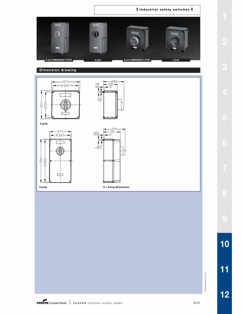
I Industr ia l safety switches I
6-pole EMERGENCY STOP 6-pole 3-pole EMERGENCY STOP 3-pole
Dimension drawing
3-pole
6-pole X = fixing dimensions
X 247
271
X 247
271
20013511 Ø
12
Ø 7
X 247
271
X 520
544
27521111
Ø 12
Ø 7
1
2
3
4
5
6
7
8
9
10
11
12

10.48 C O O P E R C R O U S E - H I N D S G M B H
I Industr ia l safety switches I
3-pole 3-pole EMERGENCY STOP 6-pole 6-pole EMERGENCY STOP
Technical data
Industr ia l-Safety switch 160 A
Permissible ambient temperature –20 °C to +40 °C
Rated voltage up to max. 690 V
Rated current max. 160 A
Frequency 50/60 Hz
Rated making-/breaking capacity AC-3 Ue 230 V / Ie 160 A
accd. to EN 60947-3 Ue 400 V / Ie 160 A
Ue 500 V / Ie 160 A
Ue 690 V / Ie 160 A
Back-up fuse up to 400 V AC: 250 A gL
up to 500 V AC: 250 A gL
up to 690 V AC: 200 A gL
Connecting terminals Main contact 1 x 95 mm2
Auxiliary-/Signal contact 2 x 4 mm2
Insulation class I
Degree of protection accd. EN 60529 IP66
Cable glands/enclosure drilling M25 (d = 8 - 17 mm) see ordering details
M63 (d = 27 - 48 mm) see ordering details
Double cable end box (d = 46 -72 mm)
Option: metal flange with 2 x thread
Weight 3-pole approx. 9.00 kg
6-pole approx. 16.50 kg
Enclosure material glass-fibre reinforced polyester
Enclosure colour black
Auxiliary contact 1 x NO making - lagging; breaking - leading
1 x NC making - leading; breaking - lagging
Padlocking can be locked in OFF position with 3 commercially available padlocks

I Industr ia l safety switches I
C O O P E R C R O U S E - H I N D S G M B H 10.49
6-pole EMERGENCY STOP 6-pole 3-pole EMERGENCY STOP 3-pole
Ordering detai ls
Version Cable entry Order No.
Industrial-Safety switch 160 A 3-pole
Version with 4 auxiliary contacts (2 x NO; 2 x NC)
3-pole 2 x M63 / 1 x M25 GHG 981 0031 R0003
3-pole EMERGENCY STOP 2 x M63 / 1 x M25 on request
Industrial-Safety switch 160 A 6-pole
Version with 4 auxiliary contacts (2 x NO; 2 x NC)
6-pole 4 x M50 / 1 x M25 GHG 981 0032 R0001
6-pole EMERGENCY STOP 4 x M50 / 1 x M25 GHG 981 0032 R0002
Customized version on request
Accessories
Mounting plate for industrial-safety switch
Type Application Fixing technique Order No.
Size 3 2 x Pipe mounting screw-on1) GHG 610 1953 R0110
1) observe mounting distance
Accessories for mounting plates
Type OU Order No.
Label holder with label (unlabelled) for mounting plates size 1, 2, 2A and 3 10 GHG 610 1953 R0057
Installation kit for pipes 1” (of 27 - 30 mm) for mounting plates for pipe mounting 10 GHG 610 1953 R0020
Please note that we can only deliver in the ordering units (OU) stated in the tables above
1
2
3
4
5
6
7
8
9
10
11
12

10.50 C O O P E R C R O U S E - H I N D S G M B H
Dim
en
sio
ns
in
mm
I Industr ia l safety switches I
3-pole 3-pole EMERGENCY STOP 6-pole 6-pole EMERGENCY STOP
Dimension drawing
3-pole
6-pole X = fixing dimensions
X 247
271
X 247
271
20013511 Ø
12
Ø 7
X 247
271
X 520
544
27521111
Ø 12
Ø 7

I Industr ia l safety switches I
C O O P E R C R O U S E - H I N D S G M B H 10.51
3-/6-pole EMERGENCY STOP 3-/6-pole
Technical data
Industr ia l-Safety switch 250 A
Permissible ambient temperature –20 °C to +40 °C
Rated voltage up to max. 690 V
Rated current max. 250 A
Frequency 50/60 Hz
Rated making-/breaking capacity AC-3 Ue 230 V / Ie 250 A
accd. to EN 60947-3 Ue 400 V / Ie 250 A
Ue 500 V / Ie 250 A
Ue 690 V / Ie 250 A
Back-up fuse up to 400 V AC: 250 A gL
up to 500 V AC: 200 A gL
up to 690 V AC: 200 A gL
Connecting terminals Main contact 3-pole 3 x 150 mm2/95 mm2
6-pole 6 x 150 mm2/2 x 95 mm2
Auxiliary-/Signal contact 2 x 4 mm2
Insulation class I
Degree of protection accd. EN 60529 IP65
Cable glands/enclosure drilling M25 (d = 8 - 17 mm) see ordering details
M63 (d = 27 - 48 mm) see ordering details
Weight 3-pole approx. 18 kg
6-pole approx. 31 kg
Enclosure material steel, powder-coated
Enclosure colour black
Auxiliary contact 1 x NO making - lagging; breaking - leading
1 x NC making - leading; breaking - lagging
Padlocking can be locked in OFF position with 3 commercially available padlocks
1
2
3
4
5
6
7
8
9
10
11
12

10.52 C O O P E R C R O U S E - H I N D S G M B H
I Industr ia l safety switches I
3-/6-pole 3-/6-pole EMERGENCY STOP
Ordering detai ls
Version Cable entry Order No.
Industrial-Safety switch 250 A 3-pole
Version with 2 auxiliary contacts (1 x NO; 1 x NC)
3-pole 2 x M63 / 1 x M25 KO 731713 W0001
3-pole EMERGENCY STOP 2 x M63 / 1 x M25 KO 731723 W0001
Industrial-Safety switch 250 A 6-pole
Version with 2 auxiliary contacts (1 x NO; 1 x NC)
6-pole 4 x M63 / 1 x M25 KO 731716 W0001
6-pole EMERGENCY STOP 4 x M63 / 1 x M25 KO 731726 W0001
Customized version on request
Dim
en
sio
ns
in
mm
Dimension drawing
3-/6-pole X = fixing dimensions
530X500450
8
X540
655
35
335

I Industr ia l safety switches I
C O O P E R C R O U S E - H I N D S G M B H 10.53
3-pole EMERGENCY STOP 3-pole
Technical data
Industr ia l-Safety switch 400 A
Permissible ambient temperature –20 °C to +40 °C
Rated voltage up to max. 690 V
Rated current max. 250 A
Frequency 50/60 Hz
Rated making-/breaking capacity AC-3 Ue 230 V / Ie 400 A
accd. to EN 60947-3 Ue 400 V / Ie 400 A
Ue 500 V / Ie 400 A
Ue 690 V / Ie 400 A
Back-up fuse up to 400 V AC: 500 A gL
up to 500 V AC: 500 A gL
up to 690 V AC: 500 A gL
Connecting terminals Main contact 3 x 150 mm2/95 mm2
Auxiliary-/Signal contact 2 x 4 mm2
Insulation class I
Degree of protection accd. EN 60529 IP65
Cable glands/enclosure drilling M25 (d = 8 - 17 mm) see ordering details
M63 (d = 27 - 48 mm) see ordering details
Weight approx. 39.50 kg
Enclosure material steel, powder-coated
Enclosure colour black
Auxiliary contact 1 x NO making - lagging; breaking - leading
1 x NC making - leading; breaking - lagging
Padlocking can be locked in OFF position with 3 commercially available padlocks
1
2
3
4
5
6
7
8
9
10
11
12

10.54 C O O P E R C R O U S E - H I N D S G M B H
I Industr ia l safety switches I
3-pole 3-pole EMERGENCY STOP
Ordering detai ls
Version Cable entry Order No.
Industrial-Safety switch 400 A 3-pole
Version with 2 auxiliary contacts (1 x NO; 1 x NC)
3-pole 2 x M63 / 1 x M25 KO 731713 X0001
3-pole EMERGENCY STOP 2 x M63 / 1 x M25 KO 731723 X0001
Customized version on request
Dim
en
sio
ns
in
mm
Dimension drawing
3-pole X = fixing dimensions
530X500450
8
X810
875
35
335

I Industr ia l safety switches I
C O O P E R C R O U S E - H I N D S G M B H 10.55
3-pole EMERGENCY STOP 3-pole
Technical data
Industr ia l-Safety switch 630 A
Permissible ambient temperature –20 °C to +40 °C
Rated voltage up to max. 690 V
Rated current max. 630 A
Frequency 50/60 Hz
Rated making-/breaking capacity AC-3 Ue 230 V / Ie 630 A
accd. to EN 60947-3 Ue 400 V / Ie 630 A
Ue 500 V / Ie 630 A
Ue 690 V / Ie 630 A
Back-up fuse up to 400 V AC: 800 A gL
up to 500 V AC: 800 A gL
up to 690 V AC: 800 A gL
Connecting terminals Main contact 3 x 240 mm2/120 mm2
Auxiliary-/Signal contact 2 x 4 mm2
Insulation class I
Degree of protection accd. EN 60529 IP65
Cable glands/enclosure drilling M25 (d = 8 - 17 mm) see ordering details
M80 (d = 62 - 68 mm) see ordering details
Weight approx. 40.50 kg
Enclosure material steel, powder-coated
Enclosure colour black
Auxiliary contact 1 x NO making - lagging; breaking - leading
1 x NC making - leading; breaking - lagging
Padlocking can be locked in OFF position with 3 commercially available padlocks
1
2
3
4
5
6
7
8
9
10
11
12
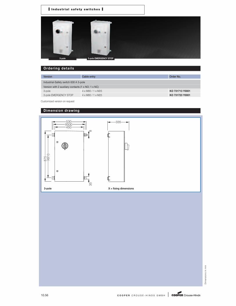
10.56 C O O P E R C R O U S E - H I N D S G M B H
I Industr ia l safety switches I
3-pole 3-pole EMERGENCY STOP
Ordering detai ls
Version Cable entry Order No.
Industrial-Safety switch 630 A 3-pole
Version with 2 auxiliary contacts (1 x NO; 1 x NC)
3-pole 4 x M80 / 1 x M25 KO 731713 Y0001
3-pole EMERGENCY STOP 4 x M80 / 1 x M25 KO 731723 Y0001
Customized version on request
Dim
en
sio
ns
in
mm
Dimension drawing
3-pole X = fixing dimensions
530X500450
8
X810
875
35
335

C O O P E R C R O U S E - H I N D S G M B H 10.57
1
2
3
4
5
6
7
8
9
10
11
12

Full AC-3 switching capacity
Cost-saving installation
Variants: star, delta, Dahlander or reversing
switches up to 80 A
Up to 40 A: snap mounting
Up to 180 A: IP66 protection
10.58
E X - M A I N C U R R E N T S W I T C H E S
CEAG main current switches in a number of
versions can be protected against inadvertent
switching on by our integrated locking facility
for up to three padlocks in the OFF position.
Full AC-3 motor switching capacities and
isolating properties according to EN 60947-4-1
with compulsory opening of the main current
contacts according to EN 60204-1 are just some
of the eminent features offered by CEAG's main
current switches.
The main current switches feature an instal -
lation-friendly design and easily accessible
connection terminals.
Versions in impact-resistant polyamide or glass-
fibre-reinforced polyester guarantee the high
degree of protection IP66 for amperages up to
180 A. These can be optionally supplied with
snap-on moulded plastic or brass flanges.
They can be equipped with screw-on flanges.
Main current switches >180 A are realized in
metal enclosures.
Internationally approved.
Up to 630 A
I Ex-Main current switches I
C O O P E R C R O U S E - H I N D S G M B H 10.59
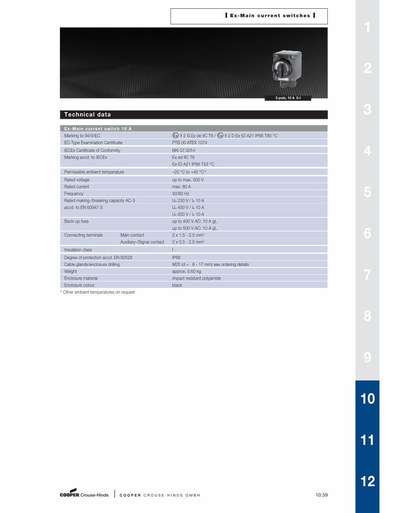
3-pole, 10 A 0-I
Technical data
Ex-Main current switch 10 A
Marking to 94/9/EC II 2 G Ex de IIC T6 / II 2 D Ex tD A21 IP66 T80 °C
EC-Type Examination Certificate PTB 00 ATEX 1074
IECEx Certificate of Conformity BKI 07.0014
Marking accd. to IECEx Ex ed IIC T6
Ex tD A21 IP66 T53 °C
Permissible ambient temperature –20 °C to +40 °C1)
Rated voltage up to max. 500 V
Rated current max. 80 A
Frequency 50/60 Hz
Rated making-/breaking capacity AC-3 Ue 230 V / Ie 10 A
accd. to EN 60947-3 Ue 400 V / Ie 10 A
Ue 500 V / Ie 10 A
Back-up fuse up to 400 V AC: 10 A gL
up to 500 V AC: 10 A gL
Connecting terminals Main contact 2 x 1.5 - 2.5 mm2
Auxiliary-/Signal contact 2 x 0.5 - 2.5 mm2
Insulation class I
Degree of protection accd. EN 60529 IP66
Cable glands/enclosure drilling M25 (d = 8 - 17 mm) see ordering details
Weight approx. 0.60 kg
Enclosure material impact resistant polyamide
Enclosure colour black
1) Other ambient temperatures on request
1
2
3
4
5
6
7
8
9
10
11
12

10.60 C O O P E R C R O U S E - H I N D S G M B H
I Ex-Main current switches I
3-pole, 10 A 0-I
Ordering detai ls
Version Cable entry Order No.
Ex-Main current switch 10 A
3-pole 0-I 2 x M25 ON-OFF switch GHG 261 0006 R0001
Customized version on request
Accessories
Mounting plate for Ex-main current switch 10 A 3-pole
Type Application Fixing technique Order No.
Size 1 Wall mounting screw-on GHG 610 1953 R0101
Size 1 Pipe mounting screw-on GHG 610 1953 R0102
Size 1 Trellis mounting screw-on GHG 610 1953 R0103
Accessories for mounting plates
Type OU Order No.
Label holder with label (unlabelled) for mounting plates size 1, 2, 2A and 3 10 GHG 610 1953 R0057
Installation kit for pipes 1” (of 27 - 30 mm) for mounting plates for pipe mounting 10 GHG 610 1953 R0020
Accessories for canopies plates
Type Application OU Order No.
Size 1 for mounting plate size 1 1 GHG 610 1955 R0101
Please note that we can only deliver in the ordering units (OU) stated in the tables above
Dim
en
sio
ns
in
mm
Dimension drawing
3-pole, 10 A 0-I X = fixing dimensions
102
X61.5
X68.584
80112
Ø 5.5
Ø 8.5

I Ex-Main current switches I
C O O P E R C R O U S E - H I N D S G M B H 10.61
3-pole, 20 A change-over 3-pole, 20 A 0-I
Technical data
Ex-Main current switch 20 A
Marking to 94/9/EC II 2 G Ex ed ia IIC T6 / II 2 D Ex tD A21 IP66 T80 °C
EC-Type Examination Certificate PTB 99 ATEX 1161
IECEx Certificate of Conformity BKI 07.0012
Marking accd. to IECEx Ee ed ia IIC T6
Ex tD A21 IP66 T55 °C
Permissible ambient temperature –20 °C to +40 °C1)
Rated voltage up to max. 690 V
Rated current max. 20 A
Frequency 50/60 Hz
Rated making-/breaking capacity AC-3 Ue 230 V / Ie 20 A
accd. to EN 60947-3 Ue 400 V / Ie 20 A
Ue 500 V / Ie 16 A
Ue 690 V / Ie 10 A
Back-up fuse up to 400 V AC: 35 A gL
up to 500 V AC: 35 A gL
up to 690 V AC: 25 A gL
Connecting terminals Main contact 2 x 4 mm2
Auxiliary-/Signal contact 2 x 0.5 - 2.5 mm2
Insulation class I
Degree of protection accd. EN 60529 IP66
Cable glands/enclosure drilling M25 (d = 8 - 17 mm) see ordering details
M32 (d = 12 - 21 mm) see ordering details
Option: metal flange with thread
Weight approx. 1.40 kg
Enclosure material glass-fibre reinforced polyester
Enclosure colour black
1) Other ambient temperatures on request
1
2
3
4
5
6
7
8
9
10
11
12
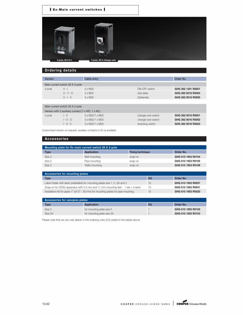
10.62 C O O P E R C R O U S E - H I N D S G M B H
I Ex-Main current switches I
3-pole, 20 A 0-I 3-pole, 20 A change-over
Ordering detai ls
Version Cable entry Order No.
Main current switch 20 A 3-pole
3-pole 0 - I 2 x M32 ON-OFF switch GHG 262 1301 R0001
0 - Y - D 3 x M32 star-delta GHG 262 0016 R0004
0 - I - II 3 x M32 Dahlander GHG 262 0016 R0005
Main current switch 20 A 3-pole
Version with 2 auxiliary contact (1 x NO; 1 x NC)
3-pole I - II 3 x M32/1 x M25 change-over switch GHG 262 0016 R0001
I - 0 - D 3 x M32/1 x M25 change-over switch GHG 262 0016 R0002
I - 0 - II 3 x M32/1 x M25 reversing switch GHG 262 0016 R0003
Customized version on request, auxiliary contacts in Ex ia available
Accessories
Mounting plate for Ex-main current switch 20 A 3-pole
Type Application Fixing technique Order No.
Size 2 Wall mounting snap-on GHG 610 1953 R0104
Size 2 Pipe mounting snap-on GHG 610 1953 R0105
Size 2 Trellis mounting snap-on GHG 610 1953 R0106
Accessories for mounting plates
Type OU Order No.
Label holder with label (unlabelled) for mounting plates size 1, 2, 2A and 3 10 GHG 610 1953 R0057
Snap-on for CEAG apparatus with 5.5 mm and 11 mm mounting feet 1 set = 4 each 10 GHG 610 1953 R0041
Installation kit for pipes 1” (of 27 - 30 mm) for mounting plates for pipe mounting 10 GHG 610 1953 R0020
Accessories for canopies plates
Type Application OU Order No.
Size 2 for mounting plate size 2 1 GHG 610 1955 R0102
Size 2A for mounting plate size 2A 1 GHG 610 1955 R0103
Please note that we can only deliver in the ordering units (OU) stated in the tables above
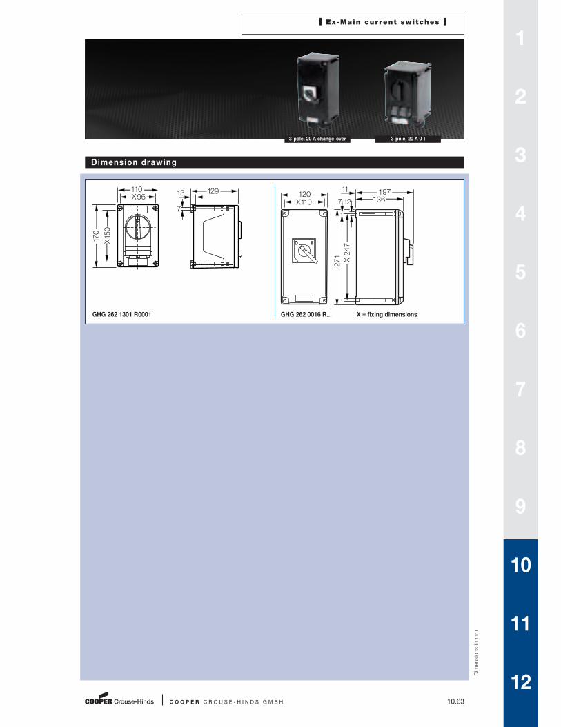
I Ex-Main current switches I
C O O P E R C R O U S E - H I N D S G M B H 10.63
3-pole, 20 A change-over 3-pole, 20 A 0-I
Dim
en
sio
ns
in
mm
Dimension drawing
GHG 262 1301 R0001 GHG 262 0016 R... X = fixing dimensions
X150
X96110
170
129
7
13 120X110
11
X 247
271
0 1
136197
127
1
2
3
4
5
6
7
8
9
10
11
12

10.64 C O O P E R C R O U S E - H I N D S G M B H
I Ex-Main current switches I
GHG 263 1301 R0001 GHG 263 0048 R....
Technical data
Ex-Main current switch 40 A
Marking to 94/9/EC II 2 G Ex de IIC T6 / II 2 D Ex tD A21 IP66 T80 °C
EC-Type Examination Certificate PTB 99 ATEX 1161
IECEx Certificate of Conformity BKI 07.0012
Marking accd. to IECEx Ex ed ia II T6
Ex tD A21 IP66 T55 °C
Permissible ambient temperature –20 °C to +40 °C1)
Rated voltage up to max. 690 V
Rated current max. 40 A
Frequency 50/60 Hz
Rated making-/breaking capacity AC-3 Ue 230 V / Ie 40 A
accd. to EN 60947-3 Ue 400 V / Ie 40 A
Ue 500 V / Ie 40 A
Ue 690 V / Ie 32 A
Back-up fuse up to 400 V AC: 80 A gL
up to 500 V AC: 80 A gL
up to 690 V AC: 63 A gL
Connecting terminals Main contact 2 x 16 mm2
Insulation class I
Degree of protection accd. EN 60529 IP66
Cable glands/enclosure drilling M25 (d = 8 - 17 mm) see ordering details
M40 (d = 16 - 28 mm) see ordering details
Option: metal flange with thread
Weight 3-pole approx. 2.30 kg
6-pole approx. 6.50 kg
Enclosure material glass-fibre reinforced polyester
Enclosure colour black
1) Other ambient temperatures on request

I Ex-Main current switches I
C O O P E R C R O U S E - H I N D S G M B H 10.65
GHG 263 0048 R.... GHG 263 1301 R0001
Ordering detai ls
Version Cable entry Order No.
Ex-Main current switch 40 A 3-pole
3-pole 0 - I 2 x M40, 1 x M25 ON-OFF switch GHG 263 1301 R0001
0 - Y - D 3 x M40, 2 x M25 screw plug star-delta GHG 263 0048 R0005
0 - I - II 3 x M40, 2 x M25 screw plug Dahlander GHG 263 0048 R0006
Safety switch 40 A 3-pole
Version with 2 auxiliary contacts (1 x NO; 1 x NC)
3-pole I - II 3 x M40/1 x M25, 1 x M25 screw plug change-over switch GHG 263 0048 R0002
I - 0 - D 3 x M40/1 x M25, 1 x M25 screw plug change-over switch GHG 263 0048 R0003
I - 0 - II 2 x M40/1 x M25, 1 x M25 screw plug reversing switch GHG 263 0048 R0004
Customized version on request, auxiliary contacts in Ex ia available
Accessories
Mounting plate for Ex-main current switch 40 A 3-pole
Type Application Fixing technique Order No.
Size 3 Wall mounting snap-on GHG 610 1953 R0118
Size 3 Pipe mounting snap-on GHG 610 1953 R0110
Size 3 Trellis mounting snap-on GHG 610 1953 R0118
Mounting plate for Ex-main current switch 40 A 6-pole
Type Application Fixing technique Order No.
Size 3 2 x Pipe mounting screw-on1) GHG 610 1953 R0110
1) observe mounting distance
Accessories for mounting plates
Type OU Order No.
Label holder with label (unlabelled) for mounting plates size 1, 2, 2A and 3 10 GHG 610 1953 R0057
Snap-on for CEAG apparatus with 5.5 mm and 11 mm mounting feet 1 set = 4 each 10 GHG 610 1953 R0041
Installation kit for pipes 1” (of 27 - 30 mm) for mounting plates for pipe mounting 10 GHG 610 1953 R0020
Accessories for canopies plates
Type Application OU Order No.
Size 3 for pipe mounting plate size 3 vertical 1 GHG 610 1955 R0104
Size 3A for wall/trellis mounting plate size 3 vertical 1 GHG 610 1955 R0105
Size 3B for pipe mounting plate size 3 horizontal 1 GHG 610 1955 R0106
Please note that we can only deliver in the ordering units (OU) stated in the tables above
1
2
3
4
5
6
7
8
9
10
11
12

10.66 C O O P E R C R O U S E - H I N D S G M B H
Dim
en
sio
ns
in
mm
I Ex-Main current switches I
GHG 263 1301 R0001 GHG 263 0048 R....
Dimension drawing
GHG 263 1301 R0001
GHG 263 0048 R... X = fixing dimensions
X197
X123-126140
225
156
7
8
X 247
271
X 247
271
275211
11 Ø 12
Ø 7
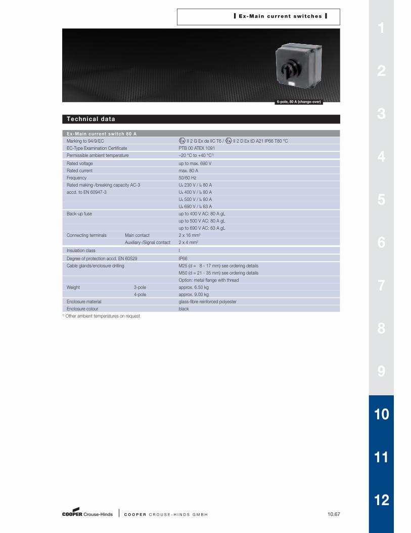
I Ex-Main current switches I
C O O P E R C R O U S E - H I N D S G M B H 10.67
6-pole, 80 A (change-over)
Technical data
Ex-Main current switch 80 A
Marking to 94/9/EC II 2 G Ex de IIC T6 / II 2 D Ex tD A21 IP66 T80 °C
EC-Type Examination Certificate PTB 00 ATEX 1091
Permissible ambient temperature –20 °C to +40 °C1)
Rated voltage up to max. 690 V
Rated current max. 80 A
Frequency 50/60 Hz
Rated making-/breaking capacity AC-3 Ue 230 V / Ie 80 A
accd. to EN 60947-3 Ue 400 V / Ie 80 A
Ue 500 V / Ie 80 A
Ue 690 V / Ie 63 A
Back-up fuse up to 400 V AC: 80 A gL
up to 500 V AC: 80 A gL
up to 690 V AC: 63 A gL
Connecting terminals Main contact 2 x 16 mm2
Auxiliary-/Signal contact 2 x 4 mm2
Insulation class I
Degree of protection accd. EN 60529 IP66
Cable glands/enclosure drilling M25 (d = 8 - 17 mm) see ordering details
M50 (d = 21 - 35 mm) see ordering details
Option: metal flange with thread
Weight 3-pole approx. 6.50 kg
4-pole approx. 9.00 kg
Enclosure material glass-fibre reinforced polyester
Enclosure colour black
1) Other ambient temperatures on request
1
2
3
4
5
6
7
8
9
10
11
12

10.68 C O O P E R C R O U S E - H I N D S G M B H
I Ex-Main current switches I
6-pole, 80 A (change-over)
Ordering detai ls
Version Cable entry Order No.
Ex-Main current switch 80 A
Version with 2 auxiliary contacts (1 x NO; 1 x NC)
4-pole 0 - I 2 x M50, 1 x M25 screw plug ON-OFF switch GHG 264 0022 R9015
without
auxiliary contact
3-pole I - 0 - II 3 x M50, 1 x M25 screw plug change-over switch GHG 264 0019 R0003
3-pole I - 0 - II 2 x M50, 1 x M25 screw plug reversing switch GHG 264 0019 R0004
Customized version on request, auxiliary contacts in Ex ia available
Accessories
Mounting plate for Ex-main current switch 80 A 3- and 4-pole
Type Application Fixing technique Order No.
Size 3 2 x Pipe mounting screw-on1) GHG 610 1953 R0110
1) observe mounting distance
Accessories for mounting plates
Type OU Order No.
Label holder with label (unlabeled) for mounting plates size 1, 2, 2A and 3 10 GHG 610 1953 R0057
Installation kit for pipes 1” (of 27 - 30 mm) for mounting plates for pipe mounting 10 GHG 610 1953 R0020
Accessories for canopies plates
Type Application OU Order No.
Size 3 for pipe mounting plate size 3 vertical 1 GHG 610 1955 R0104
Size 3A for wall/trellis mounting plate size 3 vertical 1 GHG 610 1955 R0105
Size 3B for pipe mounting plate size 3 horizontal 1 GHG 610 1955 R0106
Please note that we can only deliver in the ordering units (OU) stated in the tables above
Dim
en
sio
ns
in
mm
Dimension drawing
GHG264 0019 R.... X = fixing dimensions
X 247
271
X 247
271
295211
11 Ø 12
Ø 7

C O O P E R C R O U S E - H I N D S G M B H 10.69
1
2
3
4
5
6
7
8
9
10
11
12

Full AC-3 motor switching capacity
High degree of IP protection
Simple integration in systems
10.70
E X - P O W E R C I R C U I T B R E A K E R S
CEAG power circuit breakers enable making
or breaking of circuits under normal operating
conditions as well as cutting in, briefly conduc-
ting and cutting out currents under exceptional
conditions, such as short circuiting.
Full AC-3 motor switching capacities and iso -
lating properties according to EN 60947-4-1
with compulsory opening of the main current
contacts according to EN 60204-1 are just
some of the eminent features offered by CEAG
power circuit breakers.
Versions up to 180 A guarantee the optional high
degree of protection IP65.
The switch position is always clearly indi cated
and easily seen.
The main current switches feature an installa-
tion-friendly design and easily accessible
connection terminals.
Metal versions can be equipped with metal
screw-on flanges allowing simple integration in
system as well as cost-efficient later extensions.
These can be optionally supplied with snap-on
moulded plastic or brass flanges.
The described power circuit breakers are also
available for Explosion Group IIB, which is
sufficiant for many of the applications.
Internationally approved.
Up to 630 A
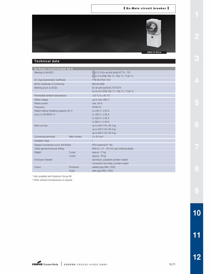
I Ex-Main c i rcui t breaker I
C O O P E R C R O U S E - H I N D S G M B H 10.71
EXKO 73 1813 A
Technical data
Ex-Power circuit breaker 63 A
Marking to 94/9/EC II 2 G Ex de ia/ib [ia/ib] IIC T4 – T61)
II 2 D IP66 T80 °C / T95 °C / T130 °C
EC-Type Examination Certificate PTB 99 ATEX 1057
IECEx Certificate of Conformity BKI 06.0006
Marking accd. to IECEx Ex de ia/ib [ia/ib] IIC T6/T5/T4
Ex tD A21 IP66 T80 °C / T95 °C / T130 °C
Permissible ambient temperature –20 °C to +40 °C2)
Rated voltage up to max. 690 V
Rated current max. 63 A
Frequency 50/60 Hz
Rated making-/breaking capacity AC-3 Ue 230 V / Ie 63 A
accd. to EN 60947-3 Ue 400 V / Ie 63 A
Ue 500 V / Ie 63 A
Ue 690 V / Ie 63 A
Back-up fuse up to 400 V AC: 80 A gL
up to 500 V AC: 80 A gL
up to 690 V AC: 80 A gL
Connecting terminals Main contact 2 x 35 mm2
Insulation class I
Degree of protection accd. EN 60529 IP54 (optional IP 65)
Cable glands/enclosure drilling M50 (d = 21 - 35 mm) see ordering details
Weight 3-pole approx. 17 kg
4-pole approx. 18 kg
Enclosure material aluminium, polyester powder-coated
connection box steel, powder-coated
Colour Enclosure pebble gray (RAL 7032)
Cover dark grey (RAL 7022)
1) Also available with Explosion Group IIB
2) Other ambient temperatures on request
1
2
3
4
5
6
7
8
9
10
11
12

10.72 C O O P E R C R O U S E - H I N D S G M B H
I Ex-Main c i rcui t breaker I
EXKO 73 1813 A
Ordering detai ls
Version Cable entry Order No.
Ex-Power circuit breaker 63 A
3-pole 2 x M50 EXKO 73 1813 A0001
4-pole 2 x M50 EXKO 73 1814 A0001
Customized version on request
Dim
en
sio
ns
in
mm
Dimension drawing
X = fixing dimensions
210
X188
215
14
46
X145
454
210

I Ex-Main c i rcui t breaker I
C O O P E R C R O U S E - H I N D S G M B H 10.73
EXKO 73 1813 B
Technical data
Ex-Power circuit breaker 125 A
Marking to 94/9/EC II 2 G Ex de ia/ib [ia/ib] IIC T4 – T61)
II 2 D IP66 T80 °C / T95 °C / T130 °C
EC-Type Examination Certificate PTB 99 ATEX 1057
IECEx Certificate of Conformity BKI 06.0006
Marking accd. to IECEx Ex de ia/ib [ia/ib] IIC T6/T5/T4
Ex tD A21 IP66 T80 °C / T95 °C / T130 °C
Permissible ambient temperature –20 °C to +40 °C2)
Rated voltage up to max. 690 V
Rated current max. 125 A
Frequency 50/60 Hz
Rated making-/breaking capacity AC-3 Ue 230 V / Ie 125 A
accd. to EN 60947-3 Ue 400 V / Ie 125 A
Ue 500 V / Ie 125 A
Ue 690 V / Ie 125 A
Back-up fuse up to 400 V AC: 160 A gL
up to 500 V AC: 160 A gL
up to 690 V AC: 160 A gL
Connecting terminasl Main contact 50/35 mm2
Insulation class I
Degree of protection accd. EN 60529 IP54 (optional IP 65)
Cable glands/enclosure drilling M50 (d = 21 - 35 mm) see ordering details
Weight 3-pole approx. 48 kg
4-pole approx. 52 kg
Enclosure material aluminium, polyester powder-coated
connection box steel, powder-coated
Colour Enclosure pebble gray (RAL 7032)
Cover dark grey (RAL 7022)
1) Also available with Explosion Group IIB
2) Other ambient temperatures on request
1
2
3
4
5
6
7
8
9
10
11
12

10.74 C O O P E R C R O U S E - H I N D S G M B H
I Ex-Main c i rcui t breaker I
EXKO 73 1813 B
Ordering detai ls
Version Cable entry Order No.
Ex-Power circuit breaker 125 A
3-pole 2 x M50 EXKO 73 1813 B0001
4-pole 2 x M50 EXKO 73 1814 B0001
Customized version on request
Dim
en
sio
ns
in
mm
Dimension drawing
X = fixing dimensions
320
X295
326
14
46
X256
639
329

I Ex-Main c i rcui t breaker I
C O O P E R C R O U S E - H I N D S G M B H 10.75
EXKO 73 1813 C
Technical data
Ex-Power circuit breaker 160 A
Marking to 94/9/EC II 2 G Ex de ia/ib [ia/ib] IIC T4 ... T61)
II 2 D IP66 T80 °C / T95 °C / T130 °C
EC-Type Examination Certificate PTB 99 ATEX 1057
IECEx Certificate of Conformity BKI 06.0006
Marking accd. to IECEx Ex de ia/ib [ia/ib] IIC T6/T5/T4
Ex tD A21 IP66 T80 °C / T95 °C / T130 °C
Permissible ambient temperature –20 °C to +40 °C2)
Rated voltage up to max. 690 V
Rated current max. 180 A
Frequency 50/60 Hz
Rated making-/breaking capacity AC-3 Ue 230 V / Ie 180 A
accd. to EN 60947-3 Ue 400 V / Ie 180 A
Ue 500 V / Ie 150 A
Ue 690 V / Ie 125 A
Back-up fuse up to 400 V AC: 210 A gL
up to 500 V AC: 210 A gL
up to 690 V AC: 210 A gL
Connecting terminals Main contact 95/50 mm2
Insulation class I
Degree of protection accd. EN 60529 IP54 (optional IP 65)
Cable glands/enclosure drilling M50 (d = 21 - 35 mm) see ordering details
Weight 3-pole approx. 48 kg
4-pole approx. 52 kg
Enclosure material aluminium, polyester powder-coated
connection box steel, powder-coated
Colour Enclosure pebble gray (RAL 7032)
Cover dark grey (RAL 7022)
1) Also available with Explosion Group IIB
2) Other ambient temperatures on request
1
2
3
4
5
6
7
8
9
10
11
12

10.76 C O O P E R C R O U S E - H I N D S G M B H
I Ex-Main c i rcui t breaker I
EXKO 73 1813 C
Ordering detai ls
Version Cable entry Order No.
Ex-Power circuit breaker 160 A
3-pole 2 x M50 EXKO 73 1813 C0001
4-pole 2 x M50 EXKO 73 1814 C0001
Customized version on request
Dim
en
sio
ns
in
mm
Dimension drawing
X = fixing dimensions
320
X295
326
14
46
X256
639
329

I Ex-Main c i rcui t breaker I
C O O P E R C R O U S E - H I N D S G M B H 10.77
EXKO 73 1813 D
Technical data
Ex-Power circuit breaker 250 A
Marking to 94/9/EC II 2 G Ex de ia/ib [ia/ib] IIC T4 ... T61)
II 2 D IP66 T80 °C / T95 °C / T130 °C
EC-Type Examination Certificate PTB 99 ATEX 1057
IECEx Certificate of Conformity BKI 06.0006
Marking accd. to IECEx Ex de ia/ib [ia/ib] IIC T6/T5/T4
Ex tD A21 IP66 T80 °C / T95 °C / T130 °C
Permissible ambient temperature –20 °C to +40 °C2)
Rated voltage up to max. 690 V
Rated current max. 250 A
Frequency 50/60 Hz
Rated making-/breaking capacity AC-3 Ue 230 V / Ie 250 A
accd. to EN 60947-3 Ue 400 V / Ie 250 A
Ue 500 V / Ie 250 A
Ue 690 V / Ie 250 A
Back-up fuse up to 400 V AC: 250 A gL
up to 500 V AC: 250 A gL
up to 690 V AC: 250 A gL
Connecting terminals Main contact 150/95 mm2
Insulation class I
Degree of protection accd. EN 60529 IP54 (optional IP 65)
Cable glands/enclosure drilling M63 (d = 27 - 48 mm) see ordering details
Weight 3-pole approx. 50 kg
4-pole approx. 55 kg
Enclosure material aluminium, polyester powder-coated
connection box steel, powder-coated
Colour Enclosure pebble gray (RAL 7032)
Cover dark grey (RAL 7022)
1) Also available with Explosion Group IIB
2) Other ambient temperatures on request
1
2
3
4
5
6
7
8
9
10
11
12
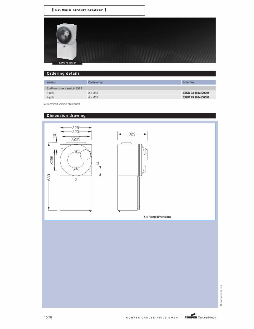
10.78 C O O P E R C R O U S E - H I N D S G M B H
I Ex-Main c i rcui t breaker I
EXKO 73 1813 D
Ordering detai ls
Version Cable entry Order No.
Ex-Main current switch 250 A
3-pole 2 x M63 EXKO 73 1813 D0001
4-pole 4 x M63 EXKO 73 1814 D0001
Customized version on request
Dim
en
sio
ns
in
mm
Dimension drawing
X = fixing dimensions
320
X295
326
14
46
X256
639
329
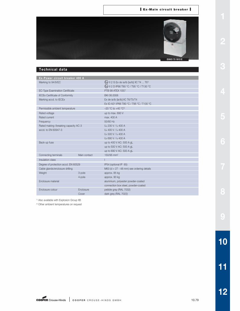
I Ex-Main c i rcui t breaker I
C O O P E R C R O U S E - H I N D S G M B H 10.79
EXKO 73 1813 E
Technical data
Ex-Power circuit breaker 400 A
Marking to 94/9/EC II 2 G Ex de ia/ib [ia/ib] IIC T4 ... T61)
II 2 D IP66 T80 °C / T95 °C / T130 °C
EC-Type Examination Certificate PTB 99 ATEX 1057
IECEx Certificate of Conformity BKI 06.0006
Marking accd. to IECEx Ex de ia/ib [ia/ib] IIC T6/T5/T4
Ex tD A21 IP66 T80 °C / T95 °C / T130 °C
Permissible ambient temperature –20 °C to +40 °C2)
Rated voltage up to max. 690 V
Rated current max. 400 A
Frequency 50/60 Hz
Rated making-/breaking capacity AC-3 Ue 230 V / Ie 400 A
accd. to EN 60947-3 Ue 400 V / Ie 400 A
Ue 500 V / Ie 400 A
Ue 690 V / Ie 400 A
Back-up fuse up to 400 V AC: 500 A gL
up to 500 V AC: 500 A gL
up to 690 V AC: 500 A gL
Connecting terminals Main contact 150/95 mm2
Insulation class I
Degree of protection accd. EN 60529 IP54 (optional IP 65)
Cable glands/enclosure drilling M63 (d = 27 - 48 mm) see ordering details
Weight 3-pole approx. 85 kg
4-pole approx. 90 kg
Enclosure material aluminium, polyester powder-coated
connection box steel, powder-coated
Enclosure colour Enclosure pebble gray (RAL 7032)
Cover dark grey (RAL 7022)
1) Also available with Explosion Group IIB
2) Other ambient temperatures on request
1
2
3
4
5
6
7
8
9
10
11
12
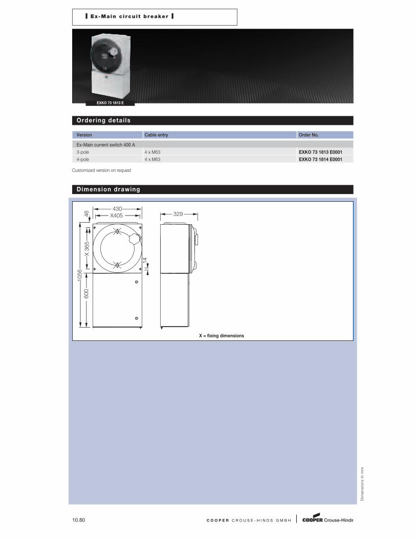
10.80 C O O P E R C R O U S E - H I N D S G M B H
I Ex-Main c i rcui t breaker I
EXKO 73 1813 E
Ordering detai ls
Version Cable entry Order No.
Ex-Main current switch 400 A
3-pole 4 x M63 EXKO 73 1813 E0001
4-pole 4 x M63 EXKO 73 1814 E0001
Customized version on request
Dim
en
sio
ns
in
mm
Dimension drawing
X = fixing dimensions
14
1056
X 365
46
600
430329X405
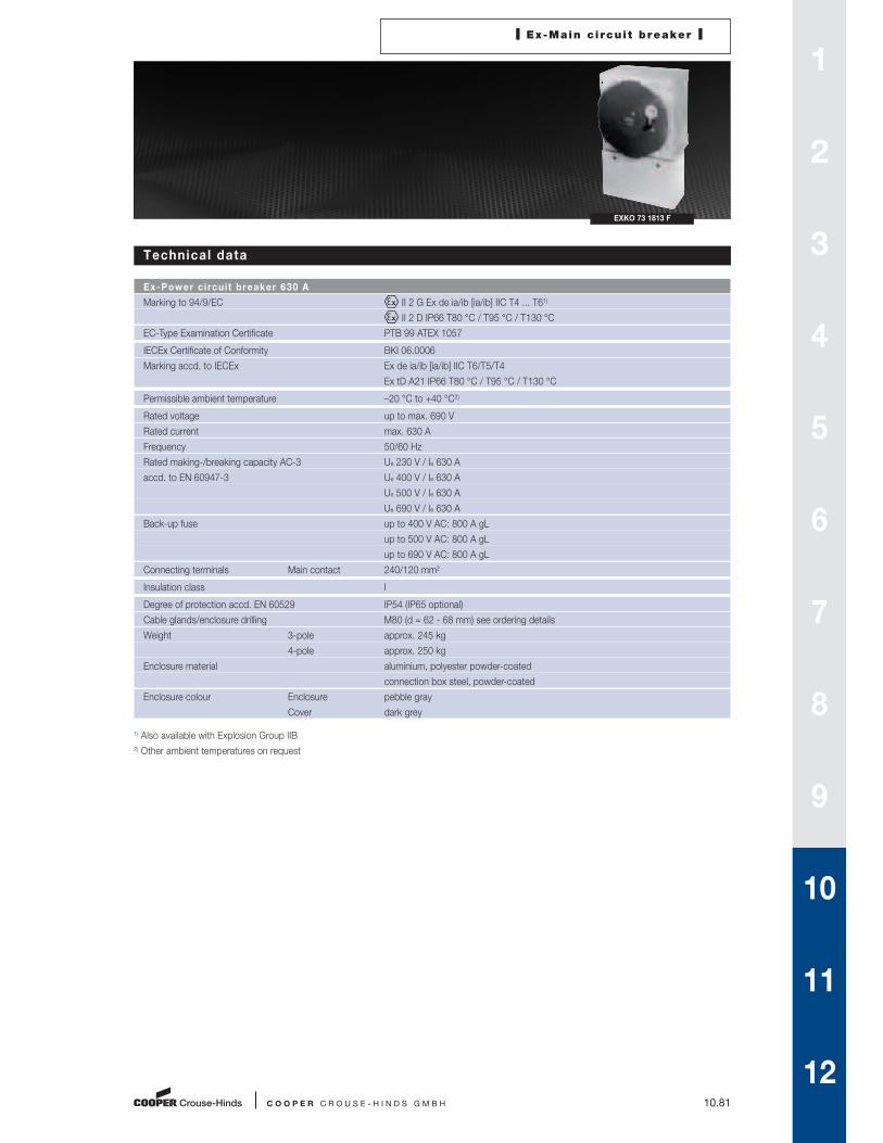
I Ex-Main c i rcui t breaker I
C O O P E R C R O U S E - H I N D S G M B H 10.81
EXKO 73 1813 F
Technical data
Ex-Power circuit breaker 630 A
Marking to 94/9/EC II 2 G Ex de ia/ib [ia/ib] IIC T4 ... T61)
II 2 D IP66 T80 °C / T95 °C / T130 °C
EC-Type Examination Certificate PTB 99 ATEX 1057
IECEx Certificate of Conformity BKI 06.0006
Marking accd. to IECEx Ex de ia/ib [ia/ib] IIC T6/T5/T4
Ex tD A21 IP66 T80 °C / T95 °C / T130 °C
Permissible ambient temperature –20 °C to +40 °C2)
Rated voltage up to max. 690 V
Rated current max. 630 A
Frequency 50/60 Hz
Rated making-/breaking capacity AC-3 Ue 230 V / Ie 630 A
accd. to EN 60947-3 Ue 400 V / Ie 630 A
Ue 500 V / Ie 630 A
Ue 690 V / Ie 630 A
Back-up fuse up to 400 V AC: 800 A gL
up to 500 V AC: 800 A gL
up to 690 V AC: 800 A gL
Connecting terminals Main contact 240/120 mm2
Insulation class I
Degree of protection accd. EN 60529 IP54 (IP65 optional)
Cable glands/enclosure drilling M80 (d = 62 - 68 mm) see ordering details
Weight 3-pole approx. 245 kg
4-pole approx. 250 kg
Enclosure material aluminium, polyester powder-coated
connection box steel, powder-coated
Enclosure colour Enclosure pebble gray
Cover dark grey
1) Also available with Explosion Group IIB
2) Other ambient temperatures on request
1
2
3
4
5
6
7
8
9
10
11
12

10.82 C O O P E R C R O U S E - H I N D S G M B H
I Ex-Main c i rcui t breaker I
EXKO 73 1813 F
Ordering detai ls
Version Cable entry Order No.
Ex-Main current switch 630 A
3-pole 4 x M80 EXKO 73 1813 F0001
4-pole 4 x M80 EXKO 73 1814 F0001
Customized version on request
Dim
en
sio
ns
in
mm
Dimension drawing
X = fixing dimensions
650
M20 x 2
X 600
655
X 505
1058
73 510

C O O P E R C R O U S E - H I N D S G M B H 10.83
1
2
3
4
5
6
7
8
9
10
11
12
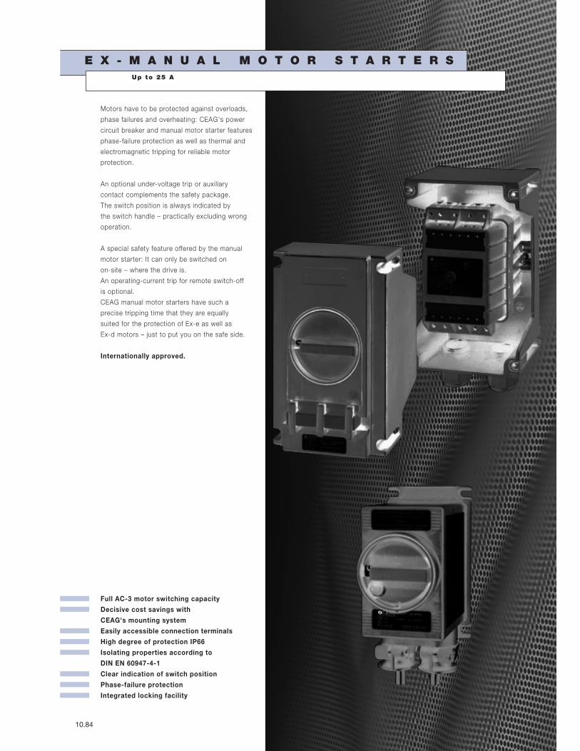
Full AC-3 motor switching capacity
Decisive cost savings with
CEAG's mounting system
Easily accessible connection terminals
High degree of protection IP66
Isolating properties according to
DIN EN 60947-4-1
Clear indication of switch position
Phase-failure protection
Integrated locking facility
10.84
E X - M A N U A L M O T O R S T A R T E R S
Motors have to be protected against over loads,
phase failures and overheating: CEAG's power
circuit breaker and manual motor starter features
phase-failure protection as well as thermal and
electromagnetic tripping for reliable motor
protection.
An optional under-voltage trip or auxiliary
contact complements the safety package.
The switch position is always indicated by
the switch handle – practically excluding wrong
operation.
A special safety feature offered by the manual
motor starter: It can only be switched on
on-site – where the drive is.
An operating-current trip for remote switch-off
is optional.
CEAG manual motor starters have such a
precise tripping time that they are equally
suited for the protection of Ex-e as well as
Ex-d motors – just to put you on the safe side.
Internationally approved.
Up to 25 A

I Ex-Manual motor starter I
C O O P E R C R O U S E - H I N D S G M B H 10.85
GHG 635 (25 A)
Technical data
Ex-Manual motor starters GHG 635 (25 A)
Marking to 94/9/EC II 2 G Ex ed IIC T5/T6 / II 2 D Ex tD A21 IP66 T80 °C
EC-Type Examination Certificate PTB 99 ATEX 1162
Permissible ambient temperature
at T6 le ≤ 16 A –20 °C to +40 °C
at T5 le > 16 A; ≤ 25 A –20 °C to +55 °C
Rated voltage up to max. 690 V
Rated current max. 25 A
Rated current auxiliary contact max. 2 A
Frequency 50/60 Hz
Rated making-/breaking capacity AC-3
accd. to EN 60947-4-1 Ue 690 V / Ie 25 A
Back-up fuse see table
Undervoltage trip tripping at 15 % - 75 % Un
can be switched on at U > 80 % Uc
Main contact 10 mm2
Auxiliary contact 2 x 0.75 - 4.0 mm2
Thermal tripping characteristic T II
Insulation class I
Degree of protection accd. EN 60529 IP66
Cable glands/enclosure drilling
0.1 - 6.3 A 2 x M25 (d = 8 - 17 mm)1)
6.3 - 25 A 2 x M32 (d = 12 - 21 mm)1)
Weight 2.5 kg
Enclosure material Glass-fibre reinforced polyester
Enclosure colour black
Padlock facility can be locked in OFF position with 3 commercially available padlocks
1) Version with aux. contact or under voltage trip with additional cable gland M25
1
2
3
4
5
6
7
8
9
10
11
12

10.86 C O O P E R C R O U S E - H I N D S G M B H
I Ex-Manual motor starter I
GHG 635 (25 A)
Short-circuit protect ion up to 100 kA and maximum backup fuse
Setting range 230 V AC 400 V AC 500 V AC 690 V AC Temp.- Order No.
lcs gL, aM lcs gL, aM lcs gL, aM lcs gL, aM class A B C R...
0.1 A ... 0.16 A T6 GHG 635 1 1 0 1 R0101
0.16 A ... 0.25 A T6 GHG 635 1 1 0 1 R0102
0.25 A ... 0.40 A T6 GHG 635 1 1 0 1 R0103
0.40 A ... 0.63 A T6 GHG 635 1 1 0 1 R0104
0.63 A ... 1.0 A T6 GHG 635 1 1 0 1 R0105
1.0 A ... 1.6 A T6 GHG 635 1 1 0 1 R0106
1.6 A ... 2.5 A 40 kA 25 A T6 GHG 635 1 1 0 1 R0107
2.5 A ... 4.0 A 40 kA 35/40 A10 kA 40 A T6 GHG 635 1 1 0 1 R0108
4.0 A ... 6.3 A 30 kA 50 A 3 kA 40 A T6 GHG 635 1 1 0 1 R0109
6.3 A ... 9.0 A 30 kA 80 A 3 kA 50 A T6 GHG 635 1 1 0 1 R0110
9.0 A ... 12.5 A 50 kA 80 A 20 kA 80 A 3 kA 50 A T6 GHG 635 1 1 0 1 R0111
12.5 A ... 16.0 A 50 kA 100 A 20 kA 100 A 3 kA 50 A T6 GHG 635 1 1 0 1 R0112
16.0 A ... 20.0 A 50 kA 100 A 20 kA 100 A 2 kA 50 A T5 GHG 635 1 1 0 1 R0113
20.0 A ... 25.0 A 50 kA 125 A 50 kA 125 A 20 kA 125 A 2 kA 50 A T5 GHG 635 1 1 0 1 R0114
Customized version on request
short-circuit proof
no backup-fuse
required
Ordering coding for special version
Description Version Undervoltage trip Auxiliary contact
GHG 635 1 A B C R...
Coding
A Version 1 = Standard version
B Undervoltage trip 0 = without undervoltage trip
1 = undervoltage trip 230 V
2 = undervoltage trip 400 V
3 = undervoltage trip 440 V
4 = undervoltage trip 500 V
5 = undervoltage trip 24 V
6 = undervoltage trip 48 V
7 = undervoltage trip 60 V
8 = undervoltage trip 110 V
9 = undervoltage trip 415 V
C Auxiliary contact 1 = without auxiliary contact
2 = with auxiliary contact 1 NO + 1 NC
3 = with auxiliary contact 2 NO

I Ex-Manual motor starter I
C O O P E R C R O U S E - H I N D S G M B H 10.87
GHG 635 (25 A)
Accessories
Mounting plate for Ex-main current switch 25 A
Type Application Fixing technique Order No.
Size 3 Wall mounting screw-on GHG 610 1953 R0118
Size 3 Pipe mounting screw-on GHG 610 1953 R0110
Size 3 Trellis mounting screw-on GHG 610 1953 R0118
Accessories for mounting plates
Type OU Order No.
Label holder with label (unlabelled) for mounting plates size 1, 2, 2A and 3 10 GHG 610 1953 R0057
Installation kit for pipes 1” (of 27 - 30 mm) for mounting plates for pipe mounting 10 GHG 610 1953 R0020
Accessories for canopies plates
Type Application OU Order No.
Size 3 for pipe mounting plate size 3 vertical 1 GHG 610 1955 R0104
Size 3A for wall/trellis mounting plate size 3 vertical 1 GHG 610 1955 R0105
Size 3B for pipe mounting plate size 3 horizontal 1 GHG 610 1955 R0106
Please note that we can only deliver in the ordering units (OU) stated in the tables above
Dim
en
sio
ns
in
mm
Dimension drawing / Wir ing diagram
GHG 635 X = fixing dimensions
156
X197
X123-126140
225
7
8
1
I >
3
I >
5
I >
14 22(12)
13 21(11)
D1D2 N PE 2 4 6
U <
D D
1
2
3
4
5
6
7
8
9
10
11
12

10.88 C O O P E R C R O U S E - H I N D S G M B H
I Ex-Manual motor starter I
GHG 635-12 Panel mounting
Technical data
Ex-Manual motor starter GHG 635-12
Marking to 94/9/EC II 2 G Ex d IIC T6 / II 2 D Ex tD A21 IP66 T80 °C
EC-Type Examination Certificate PTB 05 ATEX 1020
Permissable ambient temperature –20 °C to +40 °C
Rated voltage up to 650 V
Rated current 0.1 up to 16 A
Frequency 50/60 Hz
Rated making-/breaking capacity AC-3
accd. to EN 60947-4-1 Ue 650 V / Ie 16 A
Rated voltage undervoltage trip 230/400 V 50/60 Hz (Standard version)
440 V / 500 V / 24 V / 48 V / 60 V on request
Undervoltage trip tripping at 35 % – 70 % Uc
can be switched on at U > 85 % Uc
Back-up fuse up to 400 V AC short circuit proof up to 50 kA up to 6.3 A; 30 kA up to 16 A
Thermal ripping characteristic T II
Insulation class I
Degree of protection accd. EN 60529 IP66
Connecting cable H07RN-F (standard 3 m, other lenght on request)
Weight 1 kg (without cable)
Enclosure material Glass-fibre reinforced polyamide
Enclosure colour black
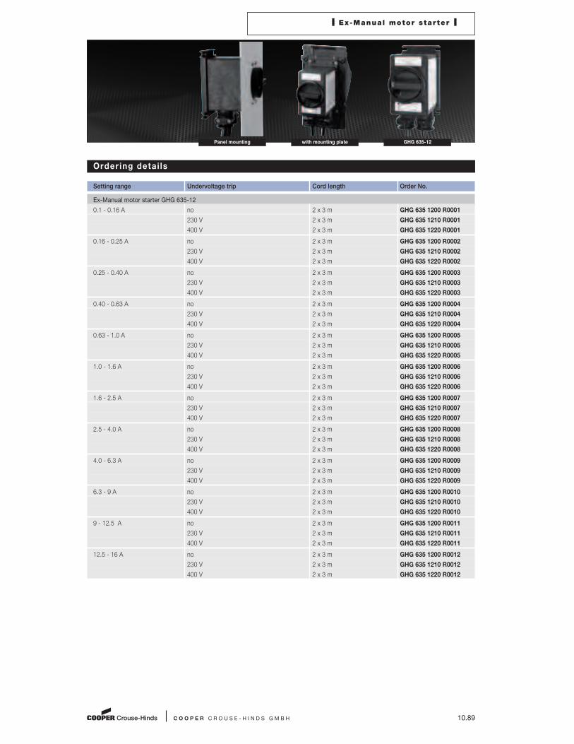
C O O P E R C R O U S E - H I N D S G M B H 10.89
Ordering detai ls
Setting range Undervoltage trip Cord length Order No.
Ex-Manual motor starter GHG 635-12
0.1 - 0.16 A no 2 x 3 m GHG 635 1200 R0001
230 V 2 x 3 m GHG 635 1210 R0001
400 V 2 x 3 m GHG 635 1220 R0001
0.16 - 0.25 A no 2 x 3 m GHG 635 1200 R0002
230 V 2 x 3 m GHG 635 1210 R0002
400 V 2 x 3 m GHG 635 1220 R0002
0.25 - 0.40 A no 2 x 3 m GHG 635 1200 R0003
230 V 2 x 3 m GHG 635 1210 R0003
400 V 2 x 3 m GHG 635 1220 R0003
0.40 - 0.63 A no 2 x 3 m GHG 635 1200 R0004
230 V 2 x 3 m GHG 635 1210 R0004
400 V 2 x 3 m GHG 635 1220 R0004
0.63 - 1.0 A no 2 x 3 m GHG 635 1200 R0005
230 V 2 x 3 m GHG 635 1210 R0005
400 V 2 x 3 m GHG 635 1220 R0005
1.0 - 1.6 A no 2 x 3 m GHG 635 1200 R0006
230 V 2 x 3 m GHG 635 1210 R0006
400 V 2 x 3 m GHG 635 1220 R0006
1.6 - 2.5 A no 2 x 3 m GHG 635 1200 R0007
230 V 2 x 3 m GHG 635 1210 R0007
400 V 2 x 3 m GHG 635 1220 R0007
2.5 - 4.0 A no 2 x 3 m GHG 635 1200 R0008
230 V 2 x 3 m GHG 635 1210 R0008
400 V 2 x 3 m GHG 635 1220 R0008
4.0 - 6.3 A no 2 x 3 m GHG 635 1200 R0009
230 V 2 x 3 m GHG 635 1210 R0009
400 V 2 x 3 m GHG 635 1220 R0009
6.3 - 9 A no 2 x 3 m GHG 635 1200 R0010
230 V 2 x 3 m GHG 635 1210 R0010
400 V 2 x 3 m GHG 635 1220 R0010
9 - 12.5 A no 2 x 3 m GHG 635 1200 R0011
230 V 2 x 3 m GHG 635 1210 R0011
400 V 2 x 3 m GHG 635 1220 R0011
12.5 - 16 A no 2 x 3 m GHG 635 1200 R0012
230 V 2 x 3 m GHG 635 1210 R0012
400 V 2 x 3 m GHG 635 1220 R0012
I Ex-Manual motor starter I
GHG 635-12with mounting platePanel mounting

10.90 C O O P E R C R O U S E - H I N D S G M B H
I Ex-Manual motor starter I
GHG 635-12 with mounting plate Panel mounting
Accessories
Mounting plate Ex-manual motor starter GHG 635-12
Type Content Order No.
Mounting plate Mounting plate for pipe mounting (1” or 2”)
and square profile 41 x 41 mm or U-profile
60 x 40 mm incl. snap-on fixing clips GHG 630 1926 R0001
Screws size 1 5 self-tapping screws for panel mounting
1 - 2 mm wall thickness GHG 630 1925 R0001
Screws size 2 5 self-tapping screws for panel mounting
2 - 3 mm wall thickness GHG 630 1925 R0002
Dim
en
sio
ns
in
mm
Dimension drawing Wiring diagram
with undervoltage trip
without undervoltage trip
GHG 635-12
129858569 11.8
38 50
4.5
51
9.8
31
ap
pro
x.
3 m
22
116
10 12 14 16 181 1,2 1,5 2
1,05
2,5 3 4 5 6
7
7,2
7,5
8 9
0,005
0,01
0,05
0,1
1
2
3
4
5
7
s 10
20
30
40
50min 1
2
3
4
5
10
h 1
2
20
lsuA
t iezesögni
ppir
Te
mittne
mehcnelcéd
ed
sp
meT
Vielfaches des EinstellstromesMultiple of setting currentMultiple de l'intensité reglée