ex260 series - smc · ex##-omn0009 si unit for profibus dp product name ex260 series model/ series
TRANSCRIPT

EX##-OMN0009
SI unit for PROFIBUS DP PRODUCT NAME
EX260 series
MODEL/ Series
-1-
EX##-OMN0009
Contents
Safety Instructions 2
How to Order 7
Summary of Product element 8
Mounting and Installation 10
General instructions on installation and maintenance 10
Connecting cables 11
LED indication and Settings 16
Troubleshooting and Maintenance 23
Specifications 27
Specifications 27
Dimensions 29
Accessories 30

-2-
EX##-OMN0009
Safety Instructions These safety instructions are intended to prevent hazardous situations and/or equipment damage. These instructions indicate the level of potential hazard with the labels of "Caution", "Warning" or "Danger". They are all important notes for safety and must be followed in addition to International standards (ISO/IEC), Japan Industrial Standards (JIS)*1) and other safety regulations*2).
*1) ISO 4414: Pneumatic fluid power - - General rules relating to systems. ISO 4413: Hydraulic fluid power - - General rules relating to systems. IEC 60204-1: Safety of machinery - -Electrical equipment of machines. (Part 1: General requirements) ISO 10218-1992: Manipulating industrial robots -Safety. JIS B 8370: General rules for pneumatic equipment. JIS B 8361: General rules for hydraulic equipment. JIS B 9960-1: Safety of machinery - Electrical equipment of machines. (Part 1: General requirements) JIS B 8433-1993: Manipulating industrial robots - Safety. etc. *2) Labor Safety and Sanitation Law, etc.
Caution : CAUTION indicates a hazard with a low level of risk which, if not avoided, could result in minor or moderate injury.
Warning : WARNING indicates a hazard with a medium level of risk which, if not avoided, could result in death or serious injury.
Danger : DANGER indicates a hazard with a high level of risk which, if not avoided, will result in death or serious injury.
Warning 1. The compatibility of the product is the responsibility of the person who designs the
equipment or decides its specifications. Since the product specified here is used under various operating conditions, its compatibility with specific equipment must be decided by the person who designs the equipment or decides its specifications based on necessary analysis and test results. The expected performance and safety assurance of the equipment will be the responsibility of the person who has determined its compatibility with the product. This person should also continuously review all specifications of the product referring to its latest catalog information, with a view to giving due consideration to any possibility of equipment failure when configuring the equipment.
2. Only personnel with appropriate training should operate machinery and equipment. The product specified here may become unsafe if handled incorrectly. The assembly, operation and maintenance of machines or equipment including our products must be performed by an operator who is appropriately trained and experienced.
3. Do not service or attempt to remove product and machinery/equipment until safety is confirmed. 1. The inspection and maintenance of machinery/equipment should only be performed after measures to prevent
falling or runaway of the driven objects have been confirmed. 2. When the product is to be removed, confirm that the safety measures as mentioned above are implemented
and the power from any appropriate source is cut, and read and understand the specific product precautions of all relevant products carefully.
3. Before machinery/equipment is restarted, take measures to prevent unexpected operation and malfunction. 4. Contact SMC beforehand and take special consideration of safety measures if the product is
to be used in any of the following conditions. 1. Conditions and environments outside of the given specifications, or use outdoors or in a place exposed to direct
sunlight. 2. Installation on equipment in conjunction with atomic energy, railways, air navigation, space, shipping, vehicles,
military, medical treatment, combustion and recreation, or equipment in contact with food and beverages, emergency stop circuits, clutch and brake circuits in press applications, safety equipment or other applications unsuitable for the standard specifications described in the product catalog.
3. An application which could have negative effects on people, property, or animals requiring special safety analysis.
4. Use in an interlock circuit, which requires the provision of double interlock for possible failure by using a mechanical protective function, and periodical checks to confirm proper operation.

-3-
EX##-OMN0009
Caution 1. The product is provided for use in manufacturing industries.
The product herein described is basically provided for peaceful use in manufacturing industries. If considering using the product in other industries, consult SMC beforehand and exchange specifications or a contract if necessary. If anything is unclear, contact your nearest sales branch.
Limited warranty and Disclaimer/Compliance Requirements The product used is subject to the following "Limited warranty and Disclaimer" and "Compliance Requirements". Read and accept them before using the product.
Limited warranty and Disclaimer 1. The warranty period of the product is 1 year in service or 1.5 years after the product is delivered.*3)
Also, the product may have specified durability, running distance or replacement parts. Please consult your nearest sales branch.
2. For any failure or damage reported within the warranty period which is clearly our responsibility, a replacement product or necessary parts will be provided. This limited warranty applies only to our product independently, and not to any other damage incurred due to the failure of the product.
3. Prior to using SMC products, please read and understand the warranty terms and disclaimers noted in the specified catalog for the particular products.
*3) Vacuum pads are excluded from this 1 year warranty. A vacuum pad is a consumable part, so it is warranted for a year after it is delivered. Also, even within the warranty period, the wear of a product due to the use of the vacuum pad or failure due to the deterioration of rubber material are not covered by the limited warranty.
Compliance Requirements When the product is exported, strictly follow the laws required by the Ministry of Economy, Trade and Industry (Foreign Exchange and Foreign Trade Control Law).
Operator ♦This operation manual has been written for those who have knowledge of machinery and apparatus that
use pneumatic equipment and have full knowledge of assembly, operation and maintenance of such equipment.
♦Please read this operation manual carefully and understand it before assembling, operating or providing maintenance to the product.

-4-
EX##-OMN0009
Precautions
Warning Do not disassemble, modify (including changing the printed circuit board) or repair. An injury or failure can result. Do not operate the product outside of the specifications. Do not use for flammable or harmful fluids. Fire, malfunction, or damage to the product can result. Verify the specifications before use. Do not operate in an atmosphere containing flammable or explosive gases. Fire or an explosion can result. This product is not designed to be explosion proof. If using the product in an interlocking circuit: •Provide a double interlocking system, for example a mechanical system. •Check the product regularly for proper operation. Otherwise malfunction can result, causing an accident. The following instructions must be followed during maintenance: •Turn off the power supply. •Stop the air supply, exhaust the residual pressure and verify that the air is released before performing maintenance.
Otherwise an injury can result.
Caution After maintenance is complete, perform appropriate functional inspections. Stop operation if the equipment does not function properly. Safety cannot be assured in the case of unexpected malfunction. Provide grounding to assure the safety and noise resistance of the Serial System. Individual grounding should be provided close to the product with a short cable.

-5-
EX##-OMN0009
NOTE Follow the instructions given below when designing, selecting and handling the product. •The instructions on design and selection (installation, wiring, environment, adjustment, operation, maintenance, etc.) described below must also be followed. Product specifications •The direct current power supply to combine should be UL1310 Class2 power supply when conformity to UL is necessary. •The SI unit is a approved product only if they have a mark on the body. •Use the specified voltage.
Otherwise failure or malfunction can result. •Reserve a space for maintenance.
Allow sufficient space for maintenance when designing the system. •Do not remove any nameplates or labels.
This can lead to incorrect maintenance, or misreading of the operation manual, which could cause damage or malfunction to the product. It may also result in non-conformity to safety standards.
•Product handling Installation •Do not drop, hit or apply excessive shock to the fieldbus system.
Otherwise damage to the product can result, causing malfunction. •Tighten to the specified tightening torque.
If the tightening torque is exceeded the mounting screws may be broken. IP67 protection cannot be guaranteed if the screws are not tightened to the specified torque. •Never mount a product in a location that will be used as a foothold.
The product may be damaged if excessive force is applied by stepping or climbing onto it.
Wiring •Avoid repeatedly bending or stretching the cables, or placing heavy load on them.
Repetitive bending stress or tensile stress can cause breakage of the cable. •Wire correctly.
Incorrect wiring can break the product. •Do not perform wiring while the power is on.
Otherwise damage to the fieldbus system and/or I/O device can result, causing malfunction. •Do not route wires and cables together with power or high voltage cables.
Otherwise the fieldbus system and/or I/O device can malfunction due to interference of noise and surge voltage from power and high voltage cables to the signal line. Route the wires (piping) of the fieldbus system and/or I/O device separately from power or high voltage cables. •Confirm proper insulation of wiring.
Poor insulation (interference from another circuit, poor insulation between terminals, etc.) can lead to excess voltage or current being applied to the product, causing damage. •Take appropriate measures against noise, such as using a noise filter, when the fieldbus system is incorporated into equipment. Otherwise noise can cause malfunction.

-6-
EX##-OMN0009
Environment •Select the proper type of protection according to the environment of operation.
IP67 protection is achieved when the following conditions are met. (1) The units are connected properly with fieldbus cable with M12 connector and power cable with M12 (M8) connector. (2) Suitable mounting of each unit and manifold valve. If using in an environment that is exposed to water splashes, please take measures such as using a cover. If the product is to be used in an environment containing oils or chemicals such as coolant or cleaning solvent, even for a short time, it may be adversely affected (damage, malfunction etc.). •Do not use the product in an environment where corrosive gases or fluids could be splashed.
Otherwise damage to the product and malfunction can result. •Do not use in an area where surges are generated.
If there is equipment which generates a large amount of surge (solenoid type lifter, high frequency induction furnace, motor, etc.) close to the fieldbus system, this may cause deterioration or breakage of the internal circuit of the fieldbus system. Avoid sources of surge generation and crossed lines. •When a surge-generating load such as a relay or solenoid is driven directly, use an fieldbus system with a built-in surge absorbing element. Direct drive of a load generating surge voltage can damage the fieldbus system. •The product is CE marked, but not immune to lightning strikes. Take measures against lightning strikes in the system. •Prevent foreign matter such as remnant of wires from entering the fieldbus system to avoid failure and malfunction. •Mount the product in a place that is not exposed to vibration or impact.
Otherwise failure or malfunction can result. •Do not use the product in an environment that is exposed to temperature cycle.
Heat cycles other than ordinary changes in temperature can adversely affect the inside of the product. •Do not expose the product to direct sunlight.
If using in a location directly exposed to sunlight, shade the product from the sunlight. Otherwise failure or malfunction can result. •Keep within the specified ambient temperature range.
Otherwise malfunction can result. •Do not operate close to a heat source, or in a location exposed to radiant heat.
Otherwise malfunction can result.
Adjustment and Operation •Set the switches by using a sharp-pointed screwdriver etc.
It may damage set switches. •Perform settings suitable for the operating conditions.
Incorrect setting can cause operation failure. For details of each setting, refer to page 17 to 18 of this manual. •Please refer to the PLC manufacturer's manual etc. for details of programming and addresses.
For the PLC protocol and programming refer to the relevant manufacturer's documentation.
Maintenance •Turn off the power supply, stop the supplied air, exhaust the residual pressure and verify the release of air before performing maintenance. There is a risk of unexpected malfunction. •Perform regular maintenance and inspections.
There is a risk of unexpected malfunction. •After maintenance is complete, perform appropriate functional inspections.
Stop operation if the equipment does not function properly. Otherwise safety is not assured due to an unexpected malfunction or incorrect operation. •Do not use solvents such as benzene, thinner etc. to clean the each unit.
They could damage the surface of the body and erase the markings on the body. Use a soft cloth to remove stains. For heavy stains, use a cloth soaked with diluted neutral detergent and fully squeezed, then wipe up the stains again with a dry cloth.

-7-
EX##-OMN0009
How to Order
EX260-SPR 1
Connector type, output specification
Fieldbus
1 M12 connector, 32 outputs, - common (PNP)
2 M12 connector, 32 ouputs, + common (NPN)
3 M12 connector, 16 outputs, - common (PNP)
4 M12 connector, 16 outputs, + common (NPN)
5 D-sub connector, 32 outputs, - common (PNP)
6 D-sub connector, 32 outputs, + common (NPN)
7 D-sub connector, 16 outputs, - common (PNP)
8 D-sub connector, 16 outputs, + common (NPN)
PR PROFIBUS DP

-8-
EX##-OMN0009
Summary of Product element <EX260-SPR1/-SPR2/-SPR3/-SPR4>
No. Element Description
1 Fieldbus interface connector (BUS OUT)
PROFIBUS DP connection *1 (M12 5-pole socket, B-coded)
2 Fieldbus interface connector (BUS IN)
PROFIBUS DP connection *1
(M12 5-pole plug, B-coded)
3 Power supply connector Power supply with load voltage for valves and operating voltage for SI unit (M12 5-pole plug, A-coded)
4 Ground terminal Functional earth (M3 screw)
5 Output connector Output signal interface for valve manifold
6 LED and switch Bus status−specific and SI unit−specific LEDs *2 Switches for setting of node address and operating mode *2
7 Mounting hole Mounting hole for connection to the valve manifold Accessories Hexagon socket head cap screw 2pcs. M3x30 screw for connection to the valve manifold
Seal cap 1pc. seal cap for unused fieldbus interface connector (BUS OUT) *1: Refer to page.11 for cabling. *2: Refer to page 16-18 for the LED indication and settings.

-9-
EX##-OMN0009
<EX260-SPR5/-SPR6/-SPR7/-SPR8>
No. Element Description
1 Fieldbus interface connector PROFIBUS DP connection *1
(D-sub 9-pole socket)
2 Power supply connector Power supply with load voltage for valves and operating voltage for SI unit (M12 5-pole plug, A-coded)
3 Ground terminal Functional earth (M3 screw)
4 Output connector Output signal interface for valve manifold
5 LED and switch Bus status−specific and SI unit−specific LEDs *2 Switches for setting of node address and operating mode *2
6 Mounting hole Mounting hole for connection to the valve manifold
Accessories Hexagon socket head cap screw 2pcs. M3x30 screw for connection to the valve manifold
*1: Refer to page 12 for cabling. *2: Refer to page 16-18 for the LED indication and settings.

-10-
EX##-OMN0009
Mounting and Installation General instructions on installation and maintenance
Connect valve manifold to the SI unit. Installation example
L 1 2 3 4 5 6 7 8 L1 120.7 136.7 152.7 168.7 184.7 200.7 216.7 L2
80 96 112 128 144 160 176
L 9 10 11 12 13 14 15 16 L1 232.7 248.7 264.7 280.7 296.7 312.7 328.7 344.7 L2 192 208 224 240 256 272 288 304
The above table shows dimensions as an example for the SY5000 series valve manifold. Connectable valve manifolds are same as for EX250 series SI unit. Refer to the EX250 series valve manifold section in the valve catalogue for valve manifold dimension.
(mm)
n n: number of valve stations
n
-11-
EX##-OMN0009
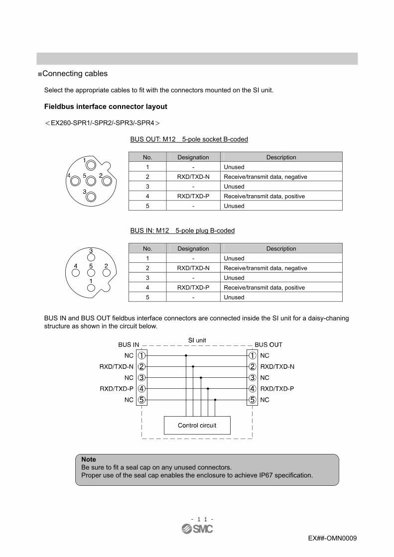
Connecting cables
Select the appropriate cables to fit with the connectors mounted on the SI unit. Fieldbus interface connector layout <EX260-SPR1/-SPR2/-SPR3/-SPR4>
BUS OUT: M12 5-pole socket B-coded
No. Designation Description 1 - Unused 2 RXD/TXD-N Receive/transmit data, negative 3 - Unused 4 RXD/TXD-P Receive/transmit data, positive
5 - Unused
BUS IN: M12 5-pole plug B-coded
No. Designation Description 1 - Unused 2 RXD/TXD-N Receive/transmit data, negative 3 - Unused 4 RXD/TXD-P Receive/transmit data, positive
5 - Unused
BUS IN and BUS OUT fieldbus interface connectors are connected inside the SI unit for a daisy-chaning structure as shown in the circuit below.
Note Be sure to fit a seal cap on any unused connectors. Proper use of the seal cap enables the enclosure to achieve IP67 specification.

-12-
EX##-OMN0009
<EX260-SPR5/-SPR6/-SPR7/-SPR8>
BUS: D-sub 9-pole socket
No. Designation Description 1 - Unused 2 - Unused
3 RXD/TXD-P Receive/transmit data, positive
4 - Unused
5 DGND Data ground (reference potential to VP)
6 VP Power supply plus (P5V) 7 - Unused
8 RXD/TXD-N Receive/transmit data, negative
9 - Unused
Use the PROFIBUS DP connector with bus cable. (e.g. 6ES7 972-0BA12-0XA0, manufactured by Siemens)

-13-
EX##-OMN0009
PROFIBUS DP bus cable A shielded twisted pair cable for PROFIBUS DP should be used. The maximum cable length depends on the transmission speed and the cable type used.
<PROFIBUS DP bus cable specification>
Cable: Shielded twisted pair cable (Type-A cable)
Impedance 135 to 165 Ω (3 to 20 MHz)Capacity between conductors Less than 30 pF/m Conductor resistance 110 Ω/km or less Wire diameter 0.64 mm or more Conductor area 0.34 mm
2 or more
・Transmission speed and maximum cable length
Transmission speed [kbps] 9.6 19.2 45.45 93.75 187.5 500 1500 12000
Cable length (m) 1200 1000 400 200 100

-14-
EX##-OMN0009
Power supply connector layout
PWR: M12 5-pole plug A-coded
No. Designation Description 1 SV24 V +24 V for solenoid valve 2 SV0 V 0 V for solenoid valve 3 SI24 V +24 V for SI unit operation 4 SI0 V 0 V for SI unit operation
5 - Unused Power-supply line for solenoid valve and power-supply line for SI unit operation are isolated. Be sure to supply power, respectively. Either single-source power or two different power can be used.
Note) Pay attention not to exceed the tolerance range of power supply voltage.

-15-
EX##-OMN0009
Ground terminal Connect the ground terminal to the ground. Resistance to ground should be 100 ohms or less.
<EX260-SPR1/-SPR2/-SPR3/-SPR4> <EX260-SPR5/-SPR6/-SPR7/-SPR8>

-16-
EX##-OMN0009
LED indication and Settings
LED indication
LED Description SF System fault BF BUS fault PWR Turns ON in green when SI unit operating voltage is supplied
PWR(V) Turns ON in green when load voltage for the valve is suppliedTurns OFF when load voltage for the valve is not supplied or outside tolerance range (19 V or less)
<Indication of communication status>
SF status BF status Description OFF OFF No fault. Communication connection to the master is established
OFF Red ON SI unit can not detect a transmission rate and the connection to the DP master has failed
OFF Red flashing SI unit has detected the transmission rate, but is not addressed by the DP master
Red ON OFF SI unit-related diasgnostic error is detected (load power for the valve is not supplied or outside tolerance range)
Red ON Red ON SI unit PROFIBUS DP address outside range
Red ON Red flashing The configuration data sent from the DP master to the SI unit dose not agree with the SI unit configuration

-17-
EX##-OMN0009
PROFIBUS DP address setting and Fail safe setting (SETTINGS)
Address can be set with the switches inside the display and switch protection cover.
Note 1.To set with switch, use a small blade screwdriver to flip the switches 2.Be sure to switch off the power when set with switch. 3.Be sure to set with the switch before use.
Switch No. No. 1 No. 2 No. 3 No. 4 No. 5 No. 6 No. 7 No. 8 - 64 32 16 8 4 2 1 1 0 0 0 0 0 0 1 2 0 0 0 0 0 1 0 3 0 0 0 0 0 1 1 4 0 0 0 0 1 0 0 : : : : : : : :
ADDRESS
125
1 1 1 1 1 0 1 CLEAR 0 OUTPUT
STATE HOLD 1
<PROFIBUS DP address setting (ADDRESS)>
Set the PROFIBUS DP address of the SI unit in binary coded form with 8-element switch. Address range is 1 to 125. * Factory default setting is Address 1.
<Fail safe setting (OUTPUT STATE)>
Set the reaction of outputs to the communication error. CLEAR: Clear all outputs. HOLD: Hold last state right before communication error. * Factory default setting is CLEAR.
0: OFF 1: ON

-18-
EX##-OMN0009
Terminator
A bus termination is reguired at both ends of PROFIBUS DP bus segment. <EX260-SPR1/-SPR2/-SPR3/-SPR4>
The bus termination switch is built-in to EX260-SPR1/-SPR2/-SPR3/-SPR4. Switch it ON if the SI unit is at the end of the fieldbus segment. *: Factory default setting is OFF.
・Internal circuit
<EX260-SPR5/-SPR6/-SPR7/-SPR8> EX260-SPR5/-SPR6/-SPR7/-SPR8 do not have a built-in termination resistor. Termination is required on the outside of the SI unit. You may use the termination switch built-in to PROFIBUS DP D-sub connector.

-19-
EX##-OMN0009
Configuration
In order to configure the SI unit in the PROFIBUS DP network, you will reguire the appropriate follwing Device master file (GSD) for the SI unit. Current GSD file can be found on the SMC website (URL http://www.smcworld.com).
GSD file
Part number GSD file 1 EX260-SPR1/-SPR2 Smc_1430.gsd 2 EX260-SPR3/-SPR4 Smc_1431.gsd 3 EX260-SPR5/-SPR6 Smc_1432.gsd 4 EX260-SPR7/-SPR8 Smc_1433.gsd
The following sections describe as an example the main configuration steps with the STEP7 software. (1) Copy the GSD file of the SI unit (Smc_143*.gsd) into the directory on your PC. (2) Start up STEP7, and execute “Options” – “Install GSD Files” from the HW Config tools. (3) Open “View” and “Catalog”, then an icon “Valves” is added underneath PROFIBUS DP – Additional
Field Devices. Drag and drop “EX260-SPR ” to under the icon “Valves”, then the icon will be added into the PROFIBUS DP line. Click the icon (a) “Save and Compile” and compile. After compiling is completed, click the icon (b) “Download to Module” and download.
Now configuration is completed.
(a) (b)
STEP7 software is manufactured by Siemens AG. STEP7 is a registered trademark for Siemens AG.

-20-
EX##-OMN0009
Output number assignment
Output data
*: Output number starts at zero and refers to the solenoid position on the manifold. *: Standard wiring on the manifold is for double-solenoid valves and output number starts A side and B side in that order as shown in
the figure a. If you mount a single-solenoid valve on the standard wiring manifold, output number for B side valve is skipped.
*: Custom wiring for mixed mounting single-solenoid valves and double-solenoid-valves can be specified with a Wiring Specification Sheet. Example wiring is shown in the figure b.
*: Bit status “0” and ”1” on a data corresponds solenoid valve status ON and OFF (0: OFF, 1: ON), and output number starts at zero from LSB (least significant bit).

-21-
EX##-OMN0009
Diagnostic information
The EX260 SI unit can support 8bytes diagnostic information, six bytes standard diagnostic information and two bytes SI unit-related diagnostic information. Diagnostic information can be requested by the DP master from the SI unit, and such system fault state can be indicated on the SF LED. The technical document states detail diagnostic information can be found on the SMC website (URL http://www.smcworld.com)
Supported SI unit-specific status is as follows.
Function Description
Solenoid valve power supply voltage monitoring
Detect when load voltage for the valve is not suppied or outside tolerance range (19 V or less)
Refer to DP master’s operation manual for details about how to monitor diagnostic information through DP master.
The following shows detail diagnostic information. (Bit status shown in the byte table is a default value. x means variable.)
Byte0:Station Status 1
Bit 7 0 0 0 0 0 x 0 0 0
Diag. Station_Non_Existent ”1” means that the SI unit not addressed by the DP master
Diag. Station_Not_Ready ”1” means that the SI unit is not ready to communicate with the DP master
Diag. Cfg_Fault ”1” means that the configuration data sent from the DP master to the SI unit dose not agree with the SI unit configuration
Diag. Ext indicate status of the extended diagnostic information area (byte 6-7)
Diag. Master_Lock ”1” means that the SI unit is addressed by different DP master
Diag. Prm_Fault ”1” means that parameter for the SI unit is invalid
Diag. Invalid_Slave_Response ”1” means that response from the SI unit is invalid
Diag. Not_Support ”1” means that diagnosis is not supported

-22-
EX##-OMN0009
Byte1:Station Status 2
Bit 7 0 0 0 x x 0 1 0 x
Byte2:Station Status 3 Bit 7 0
0 0 0 0 0 0 0 0
Byte3: Diag.Master_Add Shows the DP master address.
Byte4, 5: Ident_Number
Shows the SI unit address. Byte6: Diag.Headder
Shows the supported byte count of the extended diagnostic data. (two bytes fixed) Byte7: SI unit status information
Bit 7 0 0 0 0 0 0 0 0 0
POWER fault “1” means that load voltage for the valve is outside tolerance range
Diag. Ext_Overflow ”1” means that the extended diagnostic information overflow
Reserved
Reserved
Diag. Prm_Req ”1” means that it is in the process of the SI unit setting being changed by the DP master
Diag. Stat_Diag This bit is always “0”
Diag. WD_on ”1” means that watchdog is active
Diag. Deactivated ”1” means that the SI unit is deactivated
Reserved
Diag. Sync_Mode ”1” means that the SI unit gets Sync command
Diag. Freeze_Mode ”1” means that the SI unit gets Freeze command
Reserved

-23-
EX##-OMN0009
Troubleshooting and Maintenace Troubleshooting chart When any malfunction is observed, it is recommended to perform the following troubleshooting.
Yes
No
SI unit malfunction
SI unit PWR_LED OFF
Valves not workall valve LEDs stay off
Refer to fault No.1
SI unit PWR (V)_LED OFF
SI unit BF_LED Flash
SI unit SF_LED ON
Lower bit output onlystay off
Valves not work but valve LEDs can turn on
SI unit BF_LED ON
SI unit SF_LED ON
Refer to fault No.2
Refer to fault No.3
Refer to fault No.4
Refer to fault No.5
Refer to fault No.6
Refer to fault No.7
Refer to fault No.8
Refer to fault No.9

-24-
EX##-OMN0009
Troubleshooting table
Fault No.1
Fault Probable cause Recommended error handling Recommended action
Retighten the power cable. (Replace the cable if it is broken).
Defective power cable wiring for SI unit operation
Check the condition of the power cable wiring for SI unit operation.
Correct the power cable wiring layout.
SI unit PWR_LED OFF
SI unit operating voltage is not supplied
Check the condition of the supply voltage for SI unit operation.
Supply 24 VDC +/-10% to the SI unit operation.
Fault No.2
Fault Probable cause Recommended error handling Recommended action
Retighten the power cable. (Replace the cable if it is broken).
Defective power cable wiring for the solenoid valve
Check the condition of the power cable wiring for the valve.
Correct the power cable wiring layout.
SI unit PWR(V)_LED OFF
Load voltage for the valve is not supplied
Check the condition of the supply voltage for the valve.
Supply 24 VDC 10%/-5% to the valve.
Fault No.3
Fault Probable cause Recommended error handling Recommended action
SI unit BF_LED ON SF_LED ON
Invalid PROFIBUS address on the SI unit
Check the PROFIBUS address setting on the SI unit.
Set the valid PROFIBUS address (1 to 125) on the SI unit.
Fault No.4
Fault Probable cause Recommended error handling Recommended action
Check the condition of the bus cable wiring, and there is no broken bus cable.
Retighten the bus cable. (Replace the cable if it is broken)
Check that the bus cable length is within specification. Check that the bus termination is correctly installed at both ends of PROFIBUS DP bus segment. Check that the certified PROFIBUS cable is used.
Configure bus cables as specified by PROFIBUS DP specification.
SI unit BF_LED ON SF_LED OFF
The connection to the DP master has failed.
Check that there is no noise source or high voltage line around the bus cables.
Keep noise sources away from bus cable.
-25-
EX##-OMN0009
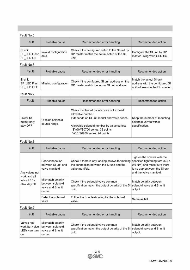
Fault No.5
Fault Probable cause Recommended error handling Recommended action
SI unit BF_LED Flash SF_LED ON
Invalid configuration data
Check if the configured setup to the SI unit by DP master match the actual setup of the SI unit.
Configure the SI unit by DP master using valid GSD file.
Fault No.6
Fault Probable cause Recommended error handling Recommended action
SI unit BF_LED Flash SF_LED OFF
Missing configuration Check if the configured SI unit address on the DP master match the actual SI unit address.
Match the actual SI unit address with the configured SI unit address on the DP master.
Fault No.7
Fault Probable cause Recommended error handling Recommended action
Lower bit output only stay OFF
Outside solenoid counts range
Check if solenoid counts dose not exceed allowable number. It depends on SI unit model and valve series. Allowable solenoid number by valve series: SY/SV/S0700 series: 32 points VQC/S0700 series: 24 points
Keep the number of mounting solenoid valves within specification.
Fault No.8
Fault Probable cause Recommended error handling Recommended action
Poor connection between SI unit and valve manifold
Check if there is any loosing screws for making the connection between the SI unit and the valve manifold.
Tighten the screws with the specified tightening torque (i.e. 0.6 Nm) and make sure there is no gap between the SI unit and the valve manifold.
Mismatch polarity between solenoid valve and SI unit output
Check if the solenoid valve common specification match the output polarity of the SI unit.
Match polarity between solenoid valve and SI unit output.
Any valves not work and all valve LEDs also stay off
Defective solenoid valve
Follow the troubleshooting for the solenoid valve.
Same as left.
Fault No.9
Fault Probable cause Recommended error handling Recommended action
Valves not work but valve LEDs can turn on
Mismatch polarity between solenoid valve and SI unit output
Check if the solenoid valve common specification match the output polarity of the SI unit.
Match polarity between solenoid valve and SI unit output.

-26-
EX##-OMN0009
Maintenance
Replacement of the SI unit Remove the M3 hexagon screw from the SI unit and release the SI unit from the valve manifold. Replace the SI unit. Tighten the screws with the specified tightening torque. (0.6 Nm) Precautions for maintenance (1) Be sure to switch off the power. (2) Check there is no foreign matter inside the SI unit. (3) Check there is no damage and no foreign matter being stuck to the gasket. (4) Be sure to tighten the screw with the specified torque
If the SI unit is not assembled properly, inside PCBs may be damaged or liquid and/or dust may enter into the unit.
Assembly and disassembly of the SI unit

-27-
EX##-OMN0009
Specifications Specifications
General specifications Item Specifications
Ambient temperature -10 to +50 oC Ambient humidity 35 to 85%RH (No condensation)
Ambient temperature for storage
-20 to +60 oC
Vibration resistance 10 to 57 Hz 0.3 mm (Constant amplitude) 57 to 150 Hz 50 m/s2 (Constant acceleration)
Impact resistance Peak value 150 m/s2 applied for 11 ms three times each in X, Y and Z directions.
Withstand voltage 500 VAC applied for 1 minute Insulation resistance 500 VDC, 10 MΩ or more Operating atmosphere No corrosive gas Pollution degree Pollution degree 2 Weight 200g or less
Electrical specifications Item Specifications
Current consumption of control power supply 21.6 to 26.4 VDC 0.1 A max. Current
consumption in power supply voltage range Solenoid valve power supply
22.8 to 26.4 VDC 2.0 A or less, according to the solenoid valve station specification
EX260-SPR1/-SPR3/-SPR5 /-SPR7 - common (PNP)
Output type EX260-SPR2/-SPR4/-SPR6
/-SPR8 + common (NPN)
Connected load Solenoid valve with light and surge voltage suppressor of 24 VDC and 1.5 W or less (manufactured by SMC)
Insulation type Photo coupler insulation type
Solenoid valve connecting specification
Residual voltage 0.4 VDC or less
Communication specifications Item Specifications
Protocol PROFIBUS DP(EN50170, EN50254)
Transmission speed 9.6, 19.2, 45.45, 93.75, 187.5, 500, 1500, 3000, 6000, 12000 (kbps)
Device type DP slave EX260-SPR1/-SPR2/-SPR5/-SPR6 32 outputs
Number of outputs EX260-SPR3/-SPR4/-SPR7/-SPR8 16 outputs EX260-SPR1/-SPR2 Smc_1430.gsd EX260-SPR3/-SPR4 Smc_1431.gsd EX260-SPR5/-SPR6 Smc_1432.gsd
Configuration file
EX260-SPR7/-SPR8 Smc_1433.gsd

-28-
EX##-OMN0009
Applicable valve series
Valve series SY series SY3000,SY5000 VQC series VQC1000,VQC2000,VQC4000 SV series SV1000, SV2000, SV3000 (10 type tie-rod base) S0700 series S0700
* The valve manifolds that can be connected are the same as those applicable to EX250 series.

-29-
EX##-OMN0009
Dimensions EX260-SPR1/-SPR2/-SPR3/-SPR4
EX260-SPR5/-SPR6/-SPR7/-SPR8

-30-
EX##-OMN0009
Accessories
Connector cable ・Compatible connectors for EX260-SPR1/-SPR2/-SPR3/-SPR4
Compatible connector Connector type
on the SI unit Description Part number Specifications Manufacturer
Communication cable for PROFIBUS DP PCA-1557691 Connector: M12 straight
Cable: 5m 1 Fieldbus interface
connector (BUS OUT) Fieldwireable connector for PROFIBUS DP PCA-1557701 Connector: M12 straight
Communication cable for PROFIBUS DP PCA-1557688 Connector: M12 straight
Cable: 5m 2 Fieldbus interface
connector (BUS IN) Fieldwireable connector for PROFIBUS DP PCA-1557714 Connector: M12 straight
EX500-AP010-S Connector: M12 straight Cable: 1m
EX500-AP050-S Connector: M12 straight Cable: 5m
EX500-AP010-A Connector: M12 angle Cable: 1m
3 Power connector Cable with power supply connector
EX500-AP050-A Connector: M12 angle Cable: 5m
SMC
・Compatible connectors for EX260-SPR5/-SPR6/-SPR7/-SPR8
Compatible connector Connector type
on the SI unit Description Part number Specifications Manufacturer
1 Fieldbus interface connector (BUS) D-sub connector 6ES7 972-0BA12
-0XA0 RS485 BUS connector SIEMENS
EX500-AP010-S Connector: M12 straight Cable: 1m
EX500-AP050-S Connector: M12 straight Cable: 5m
EX500-AP010-A Connector: M12 angle Cable: 1m
2 Power connector Cable with power connector
EX500-AP050-A Connector: M12 angle Cable: 5m
SMC
Seal cap (10 pcs.) The seal cap can be used to protect the opening M12 size connector socket, i.e. M12 “BUS OUT” connector on the EX260-SPR1/-SPR2/-SPR3/-SPR4. When M12 “BUS OUT” connector is not used, the seal cap can keep the SI unit under IP67 rated protection. (One seal cap will be attached to the SI unit EX260-SPR1/-SPR2/-SPR3/-SPR4 when shipped from factory.)
Description Part No. Specification Seal cap EX9-AWTS For M12 connector socket: 10pcs.

EX##-OMN0009
Revision history
Note: Specifications are subject to change without prior notice and any obligation on the part of the manufacturer. © 2010 SMC Corporation All Rights Reserved