examination of large scale cable …docs.neu.edu.tr/library/6679108230.pdf · comparative study of...
TRANSCRIPT

KA
RIN
A E
XA
MIN
AT
ION
OF
LA
RG
E S
CA
LE
CA
BL
E S
TR
UC
TU
RE
S IN
DIF
FE
RE
NT
NE
U
NU
RU
MO
VA
CL
IMA
TE
AN
D P
RO
PO
SA
LS
FO
R N
EU
LA
KE
AN
D P
AR
K 2
017
ME
D M
OH
AM
ED
EL
AR
AB
Y A
WA
IDIF
FE
LI T
HE
AN
AL
YS
IS A
ND
BA
RR
IER
S IN
NE
U
GR
EE
N B
UIL
DIN
G D
EV
EL
OP
ME
NT
IN L
IBY
A
2017
EXAMINATION OF LARGE SCALE CABLE
STRUCTURES IN DIFFERENT CLIMATE AND
PROPOSALS FOR NEU LAKE AND PARK
A THESIS SUBMITTED TO THE GRADUATE
SCHOOL OF APPLIED SCIENCES
OF
NEAR EAST UNIVERSITY
By
KARINA NURUMOVA
In Partial Fulfillment of the Requirements for
the Degree of Master of Science
in
Architecture
NICOSIA, 2017

Karina NURUMOVA: EXAMINATION OF LARGE SCALE CABLE STRUCTURES IN
DIFFERENT CLIMATE AND PROPOSALS FOR NEU LAKE AND PARK
Approval of Director of Graduate School of
Applied Sciences
Prof. Dr. Nadire ÇAVUŞ
We certify this thesis is satisfactory for the award of the degree of Master of Science in
Architecture
Examining Committee in Charge:
Asst.Prof.Dr. M.Selen Abbasoğlu Ermiyagil
Dr. Çilen Erçin
Dr. Raissa Kolozali
Committee Chairman, Department of
Architecture, EUL
Supervisor, Department of Architecture,
NEU
Department of Architecture, NEU

I hereby declare that all information in this document has been obtained and presented in
accordance with academic rules and ethical conduct. I also declare that, as required by
these rules and conduct, I have fully cited and referenced all material, photos and articles
that are not original to this work.
Name, Last name: Karina Nurumova
Signature:
Date:

ii
ACKNOWLEDGEMENTS
I would like to thank Dr. Çilen Erçin for her guidance, support and inspiration. She always
encouraged me in carrying out this thesis. I have highly benefitted and have gained a lot of
knowledge from Dr. Çilen Erçin.
I owe my deepest gratitude to Dr. Raissa Kolozali for her support throughout my education
and to Assoc. Prof. Dr Müjde Altın who inspired me to make my research in cable
construction.
And most importantly I want sincerely thank my family for unconditioned love and
support. This thesis would not have been possible without their faith in me.
iii
To my family…

iv
ABSTRACT
In the last years cable structures usage has been globally increased and buildings have been
widened in scale. One of the reasons of this structural system’s popularity is its driven easy
combination with the elements and materials. Representing linear tensile elements usually
produced from steel, cables have a great ability to withstand large loads and support the
structures in the diverse climatic conditions.
In this thesis history, function, construction methodology and materials have been studied
in order to investigate the conception of cable structural system to evaluate large scale
structures worldwide. Historical background review has been done to chronologize the
development of cable structures and appearance of new elements and materials used in
combination. Influence of the climatic conditions of specific regions on cables has been
examined in order to indicate possible problems solutions. As the result, table on
comparative study of large scale cable structures in different regions has been presented.
Exploration of the cable structural system gave us a chance to make design proposals for
Near East lake area and Near East Park in the last chapters of this thesis. These projects
with their contemporary style are suitable with Mediterranean climate and same time
serving as long lasting large column free space they may become new landmark of Cyprus.
This research is done in order to help to find construction solutions and materials,
considering the impact of climate on structural system, for making cable structures more
prevalent.
Keywords: Cable structures; structural system; climatic problems; materials; large scale
construction.

v
ÖZET
Son yıllarda kablo yapılarının kullanımı yaygınlaşmış ve binalarin ölçeği büyümüştür.
Farklı eleman ve malzemelerin birlikte kullanilabilmesi bu yapısal sistemin popülerliğinin
nedenlerinden biridir. Genellikle çelikten üretilen doğrusal gerilme elemanlarını temsil
eden kablolar, çeşitli iklim koşullarındaki yapıları desteklemek ve büyük yüklere
dayanmak için mükemmel bir kabiliyete sahiptirler.
Tez çalışmasında kablo yapısal sisteminin, dünya üzerindeki büyük ölçekli yapılarındaki
tarihi, işlevleri, yapı metodolojisi ve malzemeleri araştırılarak incelendi. Tarihsel geçmiş
kablo yapılarının gelişimini, kronolojikleştirmeye ve kombinasyon halinde kullanılan yeni
elementlerin ve malzemelerin görünümüne yardımcı oldu. Belirli bölgelerin iklim
koşullarının kablolara etkileri olası problem çözümleri gösterecek şekilde incelendi. Sonuç
olarak, farklı bölgelerdeki büyük ölçekli kablo yapılarının karşılaştırma çalışması tablolar
da belirtildi.
Bu tez çalışması sonucunda, kablo yapısal sisteminin araştırılması ile, Yakın Doğu göl
alanı ve Yakın Doğu Parkı için tasarım önerileri üretilmistir. Bu projeler çağdas tarzı,
Akdeniz iklimine uygunluğu ve aynı zamanda uzun geniş kolonsuz alan açıklıkları ile,
Kıbrıs'ın yeni simgesi olabilecek niteliktedir.
Bu araştırma çalışmasi ile, iklimin yapısal sistem üzerindeki etkisini göz önüne alınarak,
kablo yapılarının daha yaygın hale getirilmesi için inşaat çözümleri ve malzemeleri
bulmaya yardımcı olacaktır.
Anahtar Kelimeler: Kablolu sistem; yapısal sistem; iklimsel sorunlar; malzeme; büyük
ölçekli yapılar.

vi
TABLE OF CONTENTS
ACKNOWLEDGEMENTS ........................................................................................... ii
ABSTRACT .................................................................................................................... iv
ÖZET .............................................................................................................................. v
TABLE OF CONTENTS ............................................................................................... vi
LIST OF FIGURES ....................................................................................................... x
LIST OF ABBREVIATIONS ........................................................................................ xiv
CHAPTER 1: INTRODUCTION
1.1 Thesis Problem ...................................................................................................... 1
1.2 The Aim of the Study ............................................................................................. 1
1.3 The Importance of the Study ................................................................................. 1
1.4 Scope and Limitations of the Study ....................................................................... 2
1.5 Overview of the Cable Structure ........................................................................... 2
1.5.1 Definition of the structural system .................................................................. 2
1.5.2 Properties ......................................................................................................... 3
1.5.3 Usage ............................................................................................................... 3
1.6 Research Methodology .......................................................................................... 5
CHAPTER 2: HISTORICAL BACKGROUND
2.1 The Beginning of Cables Usage ............................................................................ 6
2.2 Appearance of First Large Scale Cable Structures ................................................ 8
2.3 Urban Scale Futuristic Ideas .................................................................................. 11
2.4 Combination of Cable Structures with Traditional Architecture ........................... 12
2.5 Contemporary Cable Structures ............................................................................. 14

vii
CHAPTER 3: CONSTRUCTION METHODOLOGY AND SYSTEM DETAILS
3.1 Characteristics and Working Principles of the System ........................................... 18
3.2 Cable Structural System Details ............................................................................. 21
3.2.1 Materials and components ................................................................................ 21
3.2.2 Cables ............................................................................................................... 22
3.2.3 Connecting elements ........................................................................................ 23
3.3 Anchorage System .................................................................................................. 29
3.4 Classification of Cable Structures ........................................................................... 30
3.4.1 Catenary types or saddle roof ........................................................................... 31
3.4.2 Arch types ........................................................................................................ 33
3.4.3 Mast types ........................................................................................................ 35
3.5 Assembly of the Primary Structural Support .......................................................... 38
3.5.1 Tall masts assembly ......................................................................................... 38
3.5.2 Spoked – wheel structure assembly ................................................................. 39
CHAPTER 4: PROBLEMS RELATED TO CLIMATIC CONDITIONS
OCCURRED IN LARGE SCALE CABLE STRUCTURES
4.1 Statement of the Climatic Conditions ..................................................................... 41
4.2 Factor of Safety for Cable Structures ..................................................................... 43
4.3 Vibration due to Temperature Change .................................................................... 43
4.4 Dynamic Effect of Wind ......................................................................................... 46
4.5 Corrosion Protection ............................................................................................... 49
4.6 Criteria of the Stability ........................................................................................... 50
4.6.1 Pre – tension of cables ...................................................................................... 51
4.6.2 Pre – stressing devices .................................................................................... 52

viii
CHAPTER 5: CASE STUDIES AND PROPOSALS
5.1 Dulles International Airport (Dulles and Chantilly, USA) ................................... 54
5.2 Burgo Paper Mill (Mantua, Italy) ......................................................................... 57
5.3 Olympic Gymnastics Arena (Seoul, Korea) ......................................................... 59
5.4 Denver International Airport (Denver, USA) ....................................................... 62
5.5 Rhoen Clinic Medical Center (Bad Neustadt, Germany) ..................................... 65
5.6 Jean – Marie Tjibaou Cultural Center (Noumea, New Caledonia / France) ......... 68
5.7 Utah Olympic Oval (Kearns, USA) ...................................................................... 71
5.8 Abuja Velodrome (Abuja, Nigeria) ...................................................................... 73
5.9 David L. Lawrence Convention Center (Pittsburgh, USA) .................................. 76
5.10 Gerald Ratner Athletics Center (Chicago, USA) ................................................ 80
5.11 Kadzielnia Amphitheatre (Kielce, Poland) ......................................................... 83
5.12 Moses Mabhida Stadium (Durban, South African Republic) ............................. 85
5.13 Khan Shatyr Entertainment Center (Astana, Kazakhstan) .................................. 89
5.14 Kauffman Center for the Performing Arts (Kansas City, USA) ......................... 94
5.15 Krasnodar Stadium (Krasnodar, Russia) ............................................................ 98
5.16 Comments and Important Points ......................................................................... 102
5.17 Proposals for the Near East University Campus (NEU lake and park) .............. 103
5.17.1 Cable structure canopy for NEU lake .......................................................... 104
5.17.2 Near East Park .............................................................................................. 107
CHAPTER 6: CONCLUSION AND RECOMMENDATIONS
6.1 Conclusion ............................................................................................................ 112
6.2 Recommendations ................................................................................................. 119
REFERENCES ............................................................................................................. 120

ix
LIST OF TABLES
Table 1: Kauffman Center list of materials ................................................................... 97
Table 2: Summary of Redaelli supplies ......................................................................... 99
Table 3: Summary of case studies ................................................................................. 102
Table 4: Cladding materials ........................................................................................... 103
Table 5: Climatic problems and their solutions ............................................................. 113
Table 6: Comparative study on large scale cable structures .......................................... 116
Table 7: Advantages and disadvanatges of cable systems............................................. 118
x
LIST OF FIGURES
Figure 1.1: Diagram of the research sequence ................................................................ 5
Figure 2.1: View of the Mt. Hope Bridge, Rhode Island ................................................ 6
Figure 2.2: Exhibition cable structures built by Vladimir Shukhov, 1895 ...................... 7
Figure 2.3: Cable structures of Lausanne expo, 1964 ..................................................... 8
Figure 2.4: View of the Montreal Expo Pavilion, 1967 .................................................. 9
Figure 2.5: Munich Olympic Stadium ............................................................................. 10
Figure 2.6: Fuller project of the dome over Manhattan ................................................... 11
Figure 2.7: Bad Hersfeld audience amphitheater in Abbey Ruin, Germany ................... 13
Figure 2.8: Combination of the masonry and cable structures in Riyadh Club .............. 14
Figure 2.9: Schlumberger Cambridge Research Center, 1985 ........................................ 15
Figure 2.10: Canada Pavilion in the Vancouver Expo, 1986 .......................................... 15
Figure 2.11: King Fahd Stadium in Saudi Arabia ........................................................... 16
Figure 3.1: Relation of loading on the shape of cables ................................................... 19
Figure 3.2: Fundamental forms of cable structures ......................................................... 20
Figure 3.3: Types of the cable strands ............................................................................. 23
Figure 3.4: Cable clamps ................................................................................................. 24
Figure 3.5: Cables crossing connection elements............................................................ 24
Figure 3.6: End fittings .................................................................................................... 25
Figure 3.7: Clamped corner edge element ....................................................................... 26
Figure 3.8: Valley and ridge cables ................................................................................. 27
Figure 3.9: Butterfly loops .............................................................................................. 27
Figure 3.10: Bale rings .................................................................................................... 28
Figure 3.11: Types of the corner plates ........................................................................... 29
Figure 3.12: Types of the anchorage systems ................................................................. 30
Figure 3.13: Catenary – like types of the cable structures .............................................. 31
Figure 3.14: Types of cable – stayed forms .................................................................... 32
Figure 3.15: Types of strut cable net forms ..................................................................... 32
Figure 3.16: The Georgia Dome stadium in Atlanta ...................................................... 33
Figure 3.17: Arch – like type .......................................................................................... 34
Figure 3.18: Brand – Briesen Airfield ............................................................................ 35
xi
Figure 3.19: The Millennium Dome, UK ....................................................................... 36
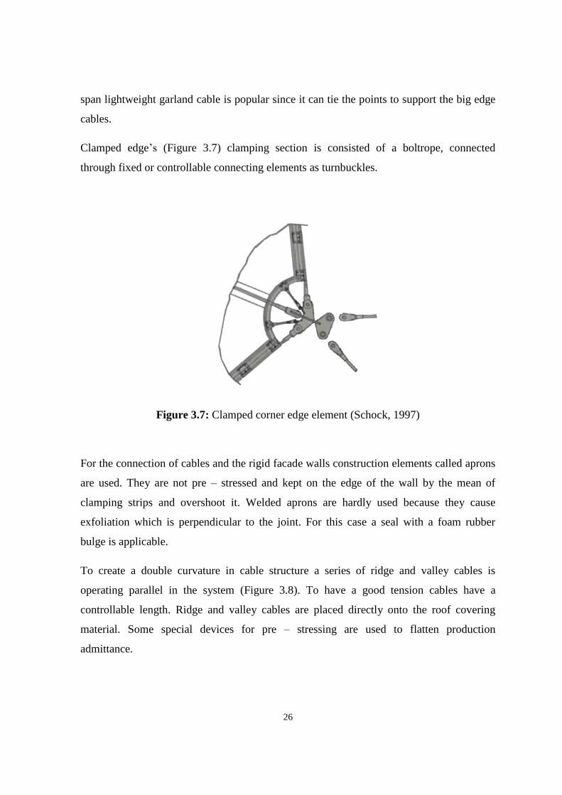
Figure 3.20: Pulling of the Khan Shatyr mast, Kazakhstan ........................................... 39
Figure 3.21: The Gottlieb Daimler Stadium, Germany .................................................. 40
Figure 4.1: Climatic conditions influence cable structures ............................................ 41
Figure 4.2: Curve of the stress – strain dependence ....................................................... 42
Figure 4.3: Details of magneto – rheological damper .................................................... 44
Figure 4.4: Cable structure’s anchorage system ............................................................. 47
Figure 4.5: Types of the connections ............................................................................. 49
Figure 4.6: Cohestrand solution ..................................................................................... 50
Figure 4.7: Example of stabilizing system in the New Deli Stadium ............................ 51
Figure 4.8: Types of the girders ..................................................................................... 52
Figure 5.1: Dulles International Airport ......................................................................... 54
Figure 5.2: Pillars view .................................................................................................. 54
Figure 5.3: System details .............................................................................................. 55
Figure 5.4: Placing of cables .......................................................................................... 56
Figure 5.5: Interior view ................................................................................................. 56
Figure 5.6: Burgo Paper Mill.......................................................................................... 57
Figure 5.7: Building under construction ......................................................................... 58
Figure 5.8: Olympic Gymnastics Arena in Seoul ........................................................... 59
Figure 5.9: System details .............................................................................................. 60
Figure 5.10: Dome installation ....................................................................................... 61
Figure 5.11: Denver International Airport...................................................................... 62
Figure 5.12: Mast detail .................................................................................................. 62
Figure 5.13: Cables and membrane ................................................................................ 63
Figure 5.14: View of the interior .................................................................................... 64
Figure 5.15: Denver International Airport cable roof .................................................... 64
Figure 5.16: Rhoen Clinic project .................................................................................. 65
Figure 5.17: Cable net .................................................................................................... 66
Figure 5.18: Silicate glass panels ................................................................................... 66
Figure 5.19: View of the huts ......................................................................................... 68
Figure 5.20: Structure of the building and steel cable structure joint system ................ 69

xii
Figure 5.21: Diagram of the cables arrangement ........................................................... 70
Figure 5.22: Utah Olympic Oval .................................................................................... 71
Figure 5.23: Masts view ................................................................................................. 71
Figure 5.24: Building section and elevation ................................................................... 72
Figure 5.25: Inside view ................................................................................................. 72
Figure 5.26: Abuja velodrome ........................................................................................ 73
Figure 5.27: Cable roof structure.................................................................................... 74
Figure 5.28: Roof plan .................................................................................................... 74
Figure 5.29: Clamping plates ......................................................................................... 75
Figure 5.30: View of the David L. Lawrence Convention Center ................................. 76
Figure 5.31: Aerial view of the convention center and Pittsburgh bridges .................... 77
Figure 5.32: Structural cables view ................................................................................ 77
Figure 5.33: David L. Lawrence Convention Center exhibition hall ............................. 78
Figure 5.34: Gerald Ratner Athletics Center .................................................................. 80
Figure 5.35: Elements of the masts ................................................................................ 81
Figure 5.36: Building section ......................................................................................... 81
Figure 5.37: Masts and cables view ............................................................................... 82
Figure 5.38: Kadzielnia Amphitheatre ........................................................................... 83
Figure 5.39: Computer model ........................................................................................ 83
Figure 5.40: Cables and membrane fixing elements ...................................................... 84
Figure 5.41: Membrane opening process ....................................................................... 84
Figure 5.42: Moses Mabhida Stadium ........................................................................... 85
Figure 5.43: Sky car and arch ......................................................................................... 86
Figure 5.44: Sky car and arch ......................................................................................... 86
Figure 5.45: Section of the building ............................................................................... 87
Figure 5.46: View of the Khan Shatyr Entertainment Center ........................................ 89
Figure 5.47: Cable system of the building ..................................................................... 90
Figure 5.48: Cables view ................................................................................................ 91
Figure 5.49: Tripod ......................................................................................................... 91
Figure 5.50: Hub and pin connection ............................................................................ 92
Figure 5.51: Kauffman Center for Performing Arts ...................................................... 94

xiii
Figure 5.52: View on the system of cables from inside ................................................ 95
Figure 5.53: Main entrance view and anchoring system ............................................... 96
Figure 5.54: View of the anchors .................................................................................. 96
Figure 5.55: Krasnodar Stadium cable structure ........................................................... 98
Figure 5.56: Cable details ............................................................................................. 100
Figure 5.57: Cable structure canopy proposal .............................................................. 104
Figure 5.58: Arch type primary support for the canopy ............................................... 104
Figure 5.59: Membrane and tribunes beneath it ........................................................... 105
Figure 5.60: Night view ................................................................................................ 105
Figure 5.61: Possible design variations of primary structural support ......................... 106
Figure 5.62: Near East Park site view .......................................................................... 107
Figure 5.63: Entrance structure and view under it ....................................................... 108
Figure 5.64: Cable - net canopy and scene ................................................................... 108
Figure 5.65: Near East Park enclosed building and their plans .................................... 109
Figure 5.66: Amphitheater view ................................................................................... 109
Figure 5.67: Cable - suspended bridge across the pond ............................................... 110
Figure 5.68: Gazebos and canopies .............................................................................. 111
Figure 5.69: Alternative system details for NEU Park ................................................. 111
Figure 6.1: Regional allocation of the cable structure examples.................................. 112
Figure 6.2: Scale development of cable structures ....................................................... 114

xiv
LIST OF ABBREVIATIONS
ETFE: Ethylene Tetrafluoroethylene
FLC: Full Locked Coil
GRB: Glass – Fiber Reinforced Polyester Resin
HDPE: High Density Polyethylene
MRD: Magneto – Rheological Damper
OSS: Open Spiral Strands
PTFE: Polytetrafluoroethylene
TMD: Tuned Mass Damper
VD: Viscous Damper
VHM: Vibration Health Monitoring
WSD: Working Stress Design

1
CHAPTER 1
INTRODUCTION
1.1 Thesis Problem
Cable structure is the pure and simple system in its form and complex composition in
application. Thesis states as the main problem structural system construction considering
climatic specifications and reveals the important aspects of building formation.
The consideration of appropriate climatic conditions and problems related to climate
occurred in cable structures are the fundamental factor which increase the functionality,
productivity and maintenance of the building.
1.2 The Aim of the Study
The aim of this research is to make an investigation of the construction methodology and
structural features of large scale cable structures of diverse regions. A comparative study
on the existing cable structure buildings built in different climatic conditions identifies its
specific construction properties and examines materials to be used with the main structural
system. Considering all factors thesis aims the proposal of new cable structure projects for
Near East Campus.
1.3 The Importance of the Study
The research provides a prior knowledge about the cable structural system details. Also
gives the chronological overview of the system development. On the example of the large
scale structures worldwide we have shown the contemporary construction methodology of
the cable systems. Thesis reveals the solutions of the climate related problem occurred in
different conditions and may serve as the guide for future works.

2
1.4 Scope and Limitations of the Study
Scope of our study is based on the structural examination of large scale cable structures
built in different climatic conditions. It identifies construction methodology, typical
problems related to cable structures and materials choice for the buildings. Limitations of
the study are associated with time and dimensions of the buildings. Minimum area has
been chosen as 2000 m² and height of the buildings minimum 25 m. NEU lake area and
Near East Park sites are selected for design proposals.
1.5 Overview of the Cable Structure
1.5.1 Definition of the structural system
Cable structural system uses tension elements to carry and transfer main forces applied to
the building. The dead loads of the prevalent structure as well as the live and other type of
loads are transmitted by the columns. Unfortunately in some building types such system
type may be inopportune. As an example, we can review a stadium. Major columns taking
loading of the building may not be placed in the center of plan to not overlap the
circulation. Exoskeleton system probably is the solution in this case, yet the roof would be
too massive and building must be scaled as well. Thereby cable structural system may
replace exoskeleton. Cables are set to the base in a distance of the formation to haul the
roofing driving out forces to anchorage points. This chance allows compression impact to
be transformed on tension and loadings are moved from the middle of the building to the
edges.
The cables by itself represent linear tensile elements. They are usually produced from steel
types and have a great ability to withstand big forces and support the structures even in the
rough climatic conditions. Cable structure can use single cables arranged parallel which
take funicular form or two – way net arrangement. Second type takes no deviations of
shape and acts more stable because here loads from internal forces carried by structure can
pass through different pathways.

3
1.5.2 Properties
Structural elements like cables are made of stainless steel, mild steel, exposed carbon
and high strength steel. They are produced from chain of tiny threads or strands which are
linked to create longer and bigger system detail. Steel cables have several types of strands:
spiral strands with inwrought round kernels and sticked by polymer, seven – stranded rope
with twisted strands and full – locked coil strand or z – shape strands with interlocking
threads.
Working principle of the cables based on the canon that cables do not take compression
force while it is under tension. Cables are subjected to the third law of Newton when all
forces applied to the object have equal response with opposite vector. For the cables it
indicates that tension loading assumed to one end of cable has identic force across the
length to counter ending. Structural cables represent rope like materials that behave in its
natural free condition as flexible and shapeless form. Structurally cable acts as a non –
rigid member that takes only tension. It has no rigidity. A cable sagging under its own
weight takes a chain like catenary shape. It is expected to take on a paraboloid shape when
uniformly loaded. Equations can be derived from these basic assumptions that relate the
tension, change in length and sag.
1.5.3 Usage
Steel cables can be used in two ways in building construction. First is suspension type of
structure roof with the conventional or a complex structural system. This way, the main
roofing is suspended by steel cables over the roof vice being supported by structural
members. Cables transfer tension force to the anchorages on the ground. These types of the
structures are called cable – stayed roofs. Cables act as simple suspension elements in
cable – stayed kind of buildings whereas roof conducts as regular load – bearing unit,
exposed under moment, shear and other influences. Yet under the wind load suspended
elements keep the tension through the loadings applied to the structure. Industrial
buildings with the suspended roof are mostly the examples of this type of construction.
4
The second possibility of cables usage in building construction is represented in the roof
types where the steel cables are presented as an acting parts of the structure. They are not
only transporters of the loads of the structure to the foundation but the main system shaper.
Such systems are called tensile structures and cables here confront different outer factors.
Behavior of the cables impacts form of the building with the new methods of fulfillment
imposition.
In the geometry, design and analysis cable structures can be simple as well as complicated.
Most of the type cables structural design requires special computer modelling. The typical
uses of this structural system are bridges, long span roof structures, membrane roofs,
railings, cable net curtain walls, etc. Cables are also used in concrete structures in steel
reinforcing to achieve longer spans with thin members (Phocas, 2013).
Being exposed and visible cable structures are presented as expression of structure. They
provide a wide variety of pure architectural forms. Le Corbusier used a 3 – inch diameter
cable net as an armature to support precast concrete panels to form a free flowing
hyperbolic paraboloid structure for a music and film festival at his landmark Philips
Pavilion of Expo 58. Cable stays are used in a radial pattern with tension and compression
rings to support the roof, providing a column-free space and an iconic image for the ceiling
of an otherwise pedestrian and uninspired building at Madison Square Garden in New
York City. Cable supports are used in a 3D triangular configuration to support the glass
panes of the renowned courtyard skylight at a much smaller scale at the Louvre (Gossen,
2004).
Nowadays, a cable net alone can provide the support for massive curtain wall made of
glass or other materials. All this examples show how different can be forms of cables
structures and how diverse can be its functions.
Cables suspended from vertical masts can be used to reduce the effective span and depth of
beams and increase the distance between columns used extensively in many exhibition and
factory buildings, for example. Cable structures represent light, efficient, more economical
buildings with great flexibility.

5
1.6 Research Methodology
To understand the subject and focus points that might be interesting to investigate
qualitative research method was used. Literature studies were conducted, including reading
of books, reports, scholarly articles, various internet sources and previous researches.
To accumulate relevant data the on – site observation and photographic documentation of
Khan Shatyr Center in Astana, Kazakhstan was done. The intensive search of cable
structure properties through a literature survey helped in the analysis and determination of
construction principles and specifications of this system. Sequence of the research is
shown in Figure 1.1.
Information about large scale buildings in different climatic regions has been collected and
analyzed. As a case studies tallest tent structure in the world Khan Shatyr Entertainment
Center, Kauffman Center for the Performing Arts, Krasnodar Stadium, Jean – Marie
Tjibaou Cultural Center, Moses Mabhida Stadium, David L. Lawrence Convention Center,
Rhoen Clinic Medical Center, Olympic Gymnastics Arena, Dulles International Airport
and Abuja Velodrome, Utah Olympic Oval, Burgo Paper Mill, Kadzielnia Amphitheatre,
Gerald Ratner Athletics Center and Denver International Airport have been presented.
Table of comparative studies between large scale structures in different climate has been
given in the conclusion chapter, influence of climatic characteristics and problem solving
was discussed and two projects for the Near East Campus has been presented.
Figure 1.1: Diagram of the research sequence (Author, 2017)

6
CHAPTER 2
HISTORICAL BACKGROUND
2.1 The Beginning of Cables Usage
The appearance of new materials and construction technologies in the history has often led
architects and civil engineers to rethink the meaning of architecture. In the last 100 years
cable structures have been developed as a new structural system from small to dramatically
large scale. Engineers inspired by the idea of minimalistic architecture and less materials
usage have sought ways to do in Buckminster Fuller’s terms more with less.
Prototypes of the cable suspended and cable stayed buildings had been nomadic tents and
cable bridges. Suspended bridges well developed technologies influenced the innovative
design of tensile structures. It allowed structural engineers to apply same principles for the
construction of large scale cable systems. Figure 2.1 shows the cable suspended Mount
Hope Bridge spanned the Narragansett Bay in Rhode Island, USA. By the time of its
construction it was fourth largest cable bridge in the USA.
Figure 2.1: View of the Mt. Hope Bridge, Rhode Island (Author, 2017)

7
Even since the German architect and engineer Frei Otto first had changed the traditional
tent to a modern building type, the enormous potential of cable – net structures for creating
building envelopes with lightweight skins has been waiting to find more widespread
realization in architectural application (Scheuermann and Boxer, 1996).
Figure 2.2: Exhibition cable structures built by Vladimir Shukhov, 1895 (English, 2000)
In Germany in the 1950’s Frei Otto first developed a theory for the design of pre – stressed
steel structures. The prototype of future works was the group of temporary exhibition
pavilions Shukhov Rotunda built by Russian Engineer Vladimir Shukhov in 1896 and
shown in Figure 2.2. Rotunda was kept closely to the large circus tent, replacing the masts
by more substantial ones or by lattice towers spanned by a ridge truss. Otto and his
collaborators produced a large number of small scale experimental fabric structures
between 1955 and 1972 with the support from the German tent manufacturing company
Stromeyer (Scheuermann and Boxer, 1996).

8
The first of early innovative structures appeared in real was a temporary Bandstand at the
Federal Garden Exhibition at Kassel in 1955. This simple four – point surface structure
were consisted of a cotton canvas stretched between two high and two low points creating
a double curved dynamic form. In 1957 more complex pre – stressed steel structures
appeared at the Garden Exhibition in Cologne, and also at the InterBau international
building exhibition in Berlin in the same year (Scheuermann and Boxer, 1996).
2.2 Appearance of First Large Scale Cable Structures
Between 1963 and 1967 Frei Otto developed the forms and techniques of cable structural
systems. Use of cable – nets at Lausanne in 1964 allowed bigger span to be achieved with
less stress placed to structural elements (Figure 2.3). This early structures laid the
foundation of discover the new structural principles which soon could be applied to much
larger scales (Filler, 2015).
Figure 2.3: Cable structures of Lausanne expo, 1964 (Filler, 2015)
The first large scale cable – net roof used in construction, rather than simple shelter,
appeared at the Montreal World Expo in 1967 (Filler, 2015).
9
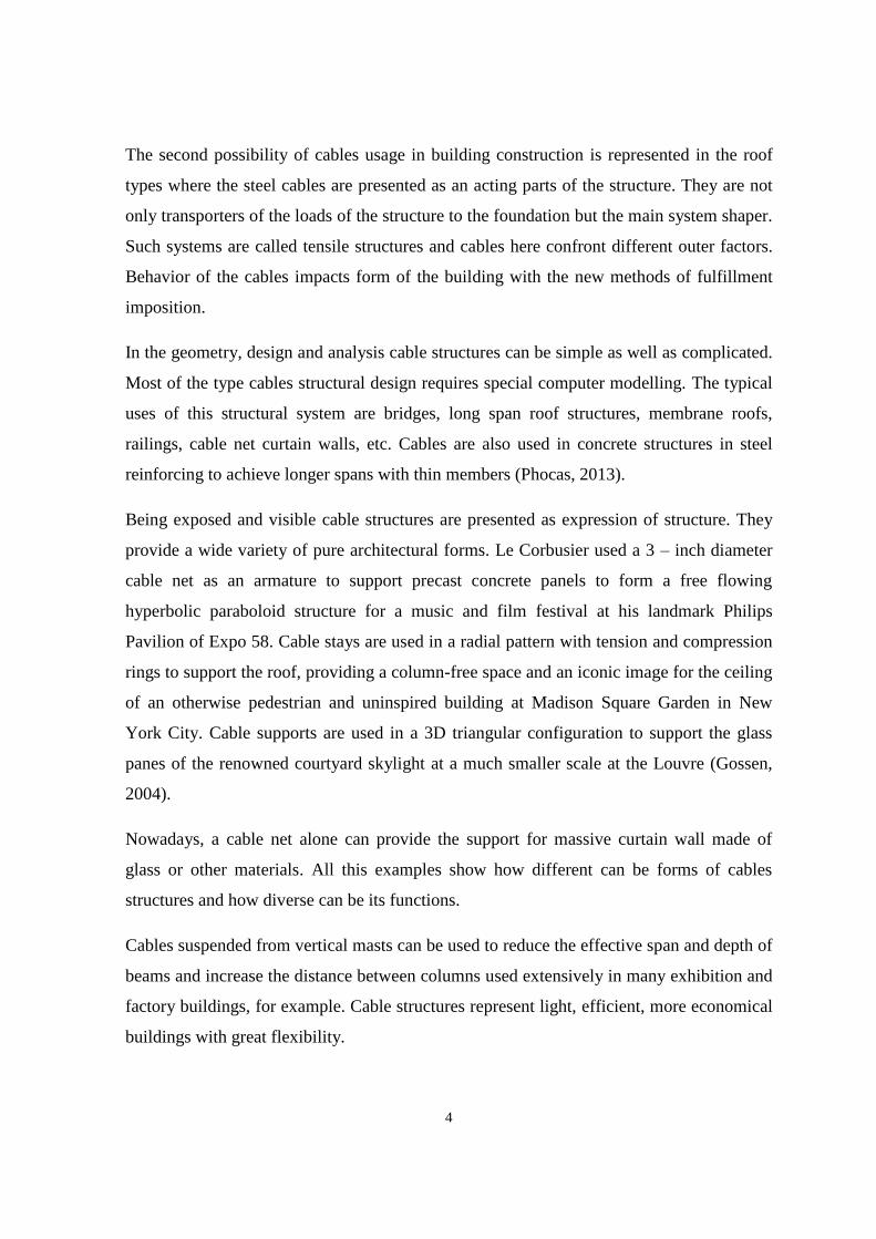
This extraordinary non classic construction by Frei Otto and Rolf Gutbrod was used to
hold the German Pavilion during exhibition and had similar principles of the construction
to Lausanne structure. By using a cable – net to support the pre – stressed membrane
suspended below it, architects were able to achieve large scale. Before the final
construction, tests were carried out on a prototype. Today this building is used to house the
Institute for Lightweight Structures (Figure 2.4).
Figure 2.4: View of the Montreal Expo Pavilion, 1967 (Warmbronn, 2015)
After this success of Montreal, a spectacular application of cable – net structures appeared
on a bigger arena, covering stadium and sport halls for the 1972 Olympic Games in
Munich. This project of German architect Gunther Behnisch and Frei Otto took the
techniques of cable structures one step further by showing how it could be combined with
glazed curtain walls to create fully closed spaces (Warmbronn, 2015).

10
An approach similar to the one which had been successfully used in Montreal was taken
over the swimming pool and arena. The huge movement joints were required at the top of
the walls to take up deflections of the roof under the loads. It showed some of the
difficulties of combining cable structure systems with other kinds of construction and gave
the new points of future research.
The main stadium at Munich shown in Figure 2.5 needed a transparent roof to avoid
shadows of the broadcast events. This was achieved by the use of the transparent sheeting
made of acryl and supported on top of the cable – net structure. These extraordinary roofs
demonstrated some new forms and proved that these structural techniques could be
successfully used in large scale applications. Apart from one or two exceptions – the Music
Bowl in Melbourne by Yuncken Freeman Irwing (1958), the Ice hockey Rink in Yale by
Saarinen (1956 – 58), the Olympic Stadium in Tokyo by Kenzo Tange (1962 – 64), all of
which used rigid rather than flexible covering materials – the techniques of pre – stressed
surface structures remained consigned mainly to temporary canopies and pavilions at
expositions and trade fairs (Scheuermann and Boxer, 1996).
Figure 2.5: Munich Olympic Stadium (Henrysson, 2012)
Early cable structures became generally associated with non – permanent use. They
suitably set in natural landscapes. Most of the structures looked temporary and stopped
architects from further pursuing the use of tensile structures. It may also have been
happened because of the difficulties to conform their curved forms with regular straight
line construction, or by difficulties of understanding the new technology.

11
2.3 Urban Scale Futuristic Ideas
Architects were inspired the futuristic ideas, proposed radical changes to the urban
environment in the 1960’s. Visions of large scale structures covering the whole cities of
futuristic layout and massive proportions appeared in sketches in the whole world. For
example, Buckminster Fuller anticipated the idea of the constructing enormous dome over
the Manhattan in New York (Figure 2.6).
Figure 2.6: Fuller project of the dome over Manhattan (Page, 2016)
A number of designs for cities of the future proposed the use of large cable structures
because of their potential for covering large spans with minimum lightweight materials.
The majority of these visions were just remains on paper, probably because of the fact that
these radical ideas completely ignored the traditional development of the towns and cities.
And also they were against the cultural context within which people used to live.
Proposal for the use of cable structures in cities at a more adaptive scale suitable for
citizens first appeared in the avant – garde architectural magazine “Archigram”. One
proposal in 1970 for the transformation of traditional English town fatefully called for the
use of minimal skins, cheek by jowl with the Edwardian store or the odd, old terraced
house. But it tended to be the more glamorous large scale mega – structures, such as the
“walking cities” projects (Scheuermann and Boxer, 1996).

12
Architects of Foster Association proposed to cover 4 acres of public space in
Hammersmith, London with a transparent roof in the 1977. It was the beginning of the
1980’s that cable structures appeared in permanent applications in the urban scale. One
more design which like the Foster proposal was never executed is Michael Hopkins and
Partners design of the enclosure of Basildon town center in 1987. It proposed to use a
10000 m² transparent tensioned roof above the part of a town (Scheuermann and Boxer,
1996).
2.4 Combination of Cable Structures with Traditional Architecture
With the development of the materials and technologies it became possible to re – think the
architecture of previous periods and adopt them to modern needs. Tendencies of
combining the cable structural systems and traditional masonry architecture began in
1980’s.
However, during the construction of first buildings difficulties and problems were found.
And most important is cable to frame connection of different materials. This process
requires completion sockets and frame contemplation. Cable completion sockets are
produced from steel corresponded at the end of a cable to tie the strands together. Length
of the conic type is nearly 5 – 6 times bigger than cable diameter (Goldsmith, 2000).
Clamps used to provide the connection between frames or masonry wall and cable may
have different forms and sizes. They should guarantee necessary tension level and protect
cable from slipping which can cause structure collapse.
One of the earliest examples of cable structures and conventional architecture was part of
the Italian architect Renzo Piano’s renovation of the Schlumberger research facilities in
Montrouge showed within a suburb of Paris in 1984. From a distance the cable roof
appeared not so different to some of the early buildings made by Frei Otto.

13
Figure 2.7: Bad Hersfeld audience amphitheater in Abbey Ruin, Germany (Nerdinger et
al., 2005)
The idea of using a cable structure in combination with traditional construction had been
applied in a very different situation 16 years before the completion of the Schlumberger
roof in Paris. To cover the audience area in the Abbey ruin at Bad Hersfeld in Germany
during the theatrical events, a retractable canopy was erected with a constant arrangement
of steel masts and cables (Figure 2.7). This structure showed some of the rapture that the
combination of a lightweight fabric skin with cable net and solid masonry could induce.
But it had no clues as how cables and masonry could be combined to form more fully self -
contained spaces.
The first built permanent structure designed to utilize masonry construction in combination
with structural cables was built to house the Diplomatic Club in Riyadh (Figure 2.8). This
building, completed in 1986, advanced the use of cable – net construction with masonry,
by attaching the lightweight structures directly to a curved inhabited wall. The massive
wall provided a curved surface to which the geometry of the conical and saddle – shaped
roofs could satisfactorily be connected in both structural and aesthetic terms (Scheuermann
and Boxer, 1996).

14
Figure 2.8: Combination of the masonry and cable structures in Riyadh Club
(Buro Happold Engineering, 2015)
The project in Riyadh showed how cable structures could be combined with traditional
construction. But Diplomatic Club building left the question if the doubly curved surfaces
of tension structures could be adapted to the straight – line geometries of traditional
structures. Many early projects tried to combine cable roofs with straight – lined
construction. It proved difficult to conjoin the scalloped edges of the roof membrane with
convention plane construction. The resulting combination looked like a badly fitting tent
attached to a shed – unless, as at Munich, the walls were carefully curved to suit the edges
of the cable structure above.
2.5 Contemporary Cable Structures
A rather sophisticated version of the “tent – on – a – shed” approach appeared in England
in 1985 set in a field outside Cambridge (Figure 2.9). First of the buildings represented as a
research facility for the Schlumberger Group, consisted of a three structures attached to
steel framed boxes. When the building appeared it attracted a great deal of complex steel
framework required to hold the cables in its shape demonstrated to what lengths the
designers had to go to adapt the geometry of the cable structure to the rectangular building
under it (Scheuermann and Boxer, 1996).

15
Figure 2.9: Schlumberger Cambridge Research Center, 1985 (Grimm, 2000)
A ship – like building appeared in Vancouver harbor replacing British Columbia Pier
during the preparations for the 1986 Expo Vancouver, Canada (Figure 2.10). This new
building, constructed to host the Canada Pavilion, used a large cable roof structure to cover
the main exhibition hall and to evoke marine fantasies. In this project a double – layer
membrane was used to improve the environmental and acoustic performance of the skin.
Canada Pavilion created a sensational view at the time came to find a permanent urban
application for an established cable – net structure deducted for permanent use as a
convention center after the Expo had finished.
Figure 2.10: Canada Pavilion in the Vancouver Expo, 1986 (Chan, 2016)

16
The general acceptance of the use of cable roofs for conventional permanent buildings was
yet not spreading, at least in Europe, perhaps because the Vancouver building was another
exhibition derivation and the building in Cambridge was a facility with experimental
binding. In America the use of cable structures for large scale out – of – town and city
center shopping malls, sport stadiums had begun to be more common.
More comparable with the Munich stadium structure example and built some ten years
later is the King Fahd Stadium roof in Riyadh shown in the Figure 2.11. Twenty four equal
units were arranged in a circle and provided a shade to 52000 m² of seating and
surrounding. The fabric is supported by steel cables, stretched between tall main mast,
stayed inclined secondary mast, ring cable and two ground anchorages. This support cable
structural system was erected first and the membrane was then laid out on the ground,
dragged out the mast, attached to the cables, sewed together, and finally stressed
(Mainstone, 2001).
Figure 2.11: King Fahd Stadium in Saudi Arabia (Roberts, 2015)

17
After the 2000’s the great boom of cable structure construction of a large scale appeared
worldwide. This period inaugurated the new era of cable buildings and the time of new
techniques to be used. Every year the amount of built large scale cable structures such as
stadiums, shopping and convenient centers, etc. is increasing. The most famous and
interesting examples will be discussed in Chapter 5.

18
CHAPTER 3
CONSTRUCTION METHODOLOGY AND SYSTEM DETAILS
3.1 Characteristics and Working Principles of the System
In the last years, cable structures became more useful and attractive. Cable systems are
becoming more widespread because of cables’ legerity, absolute length and flexibility. It
give architects more freedom of imagination and work. The compound of cables with roof
material signifies the value of transparency and lightness of forms. Innovations in shape is
one more reason of cables’ popularity nowadays. To reach new appearance and marvelous
forms, shape of the structure is changing with the cable structure.
The application specification of cable structures and system details are reviewed in this
chapter. In view of definition, there seems to be some dispute meanings of cable structures.
Followed by the literature review, cable structures are introduced and considered as the
non – rigid, flexible matter shaped in a certain way and secured by fixed endings or
anchorages which can bear the loads and span spaces. Cables transmit loads only through
simple normal stresses either through tension or compression. Any two cables with
different points of suspension can be bound together and form a suspension cable structural
system. Cables exposed to external loads would deform in a way depending on the
magnitude and position of external forces. This form obtained by the cable is called the
funicular form of the cable.
Form active structural systems redirect external forces by simple normal stresses; for
example, the arch by compression or the suspension cable by tension. The load - bearing
mechanism of this systems vests essentially on the form of materials. Any variations in
loads and support state the form of the cableway. Conditions of the loads are rigorously
governed by the natural flow in the form active systems. To understand the principles of
cable supports vertical loading, need to examine a cable suspended between two points,
fixed at the same level and bearing a load at middle of the span. Cable in this case takes a
symmetrical triangle shape. Load is transported to the supports by simple tension through
parts of the cable.

19
The triangular shape is characterized by the sag of deflection: the vertical distance between
the supports and the lowest point in the cable. Cable does not transfer the load without the
sag which would be horizontal because of the tensile forces in this case. Horizontal forces
cannot compensate the vertical loading. The pull which is not divided of the sagging
buckling cable can be separated to components:
• Downward force (equal to half of the load);
• Horizontal inward thrust or impulse.
The thrust is in inverse ratio to the sag divided to the sag doubled to the impulse. Big
number of sag raises the cable length, but decreases the tensile force. It affords shrinking
of the cross – section. For the best quantity of sag the total volume of cable cross – section
multiplied by length should be minimal. Optimal sag is equal to half of the span; it
conforms to a 45o triangle configuration with thrust P/2 (where P is the load) (Travas and
Kozar, 2008).
Figure 3.1: Relation of loading on the shape of cables (Ambrose and Tripeny, 2016)
Cable changes its shape as it shown in Figure 3.1 above when the load is shifted from the
middle of the span. Cable fits itself by taking a new form when two same loads are applied
on the cable in symmetrical way.

20
By handling of the boundary conditions of tensile cover material cables can take three
fundamental forms such as hypar, conus or barrel vault shown in Figure 3.2. Hypar or
hyperbolic paraboloid is formed by the raise of two corners with cable supported edge.
Conic shape can be achieved by the introduction and lift of central ring. To form barrel
vault typed cable structure it is needed to set the curvature to two continuously clamped
edges.
Figure 3.2: Fundamental forms of cable structures (Bing, 2004)
Cable structures are categorized into suspension structures or cable – stayed structured
suspension structures with three sub-classifications:
1. Single Curvature Structures;
2. Double Curvature Structures;
3. Double Cable Structures.
Single curvature structures are parallel cables which support exterior beams. Its number
decreases by the growth of the amount of dead load applied to the structure.
Double curvature structures represent the area of crossed cables which form a system
fading itself. They resist tremble very well.
Double cable structures indicate a composition of low and up series of cables. They are pre
– tensioned by the mean of compression braces or ties. Their stiffness and resistance to
buckling is very high.
Steel cables are the ideal structural element for large spanning because of its high tensile
strength capacity of simple tension. Cables are flexible because of their greater dimensions

21
compared to the lengths. The tensile load is equally divided between the cable strands
when irregular stresses to bending are denied by flexibility.
Levity of the flexible cable in a suspended condition is the minus of the structural system.
It can be widely liquidated by pre-stressing so cables will gain friction force that is directed
upward.
3.2 Cable Structural System Details
3.2.1 Materials and components
Since cast steel was used for the construction of the Olympic Park (Munich, Germany), its
workability has been enlarged. The great moldability of this metal is a crucial point in the
manufacture of the cable components. Cast steel is chosen for the specific properties of this
material.
Cast steel allows double – curved and free shaped forms to be constructed to meet certain
asks in loading, design and components detailing. Cast elements are usually used in
members where a large number of bars, rods or other elements meet each other or when
cables join or redirect, and where the cover material is fixed to the primary cables
structural system.
The process of modeling and the molding is defined by the quantity of details. The models
are usually constructed of wood, and molds are hand – made from sand in individual boxes
in series of up to twenty units.
When the matter cannot be shown in drawings because of it complicated shape, it is
possible to make a primary casting test or full – size model before starting a mass
production.
Stainless steel is used in a production of primary load – bearing elements. When special
surface quality is specified and great resistance to corrosion is required stainless steel plays
a big role.

22
Pure steel surface may be specified with steel – and – glass forms for the good view of the
building. Stainless steel sometimes used for this reasons. This material gives attractive
appearance and good perception of the whole structure.
The crucial decisions considered in choosing stainless steel are the strength standards,
resistance to corrosion and superficies quality. High – strength types are usually produced
by cold – forming process when welded connections have the durability only of the
original material used.
Important dissimilarities in comparison to other types of steel are different type of stability,
low modulus of elasticity and different coefficient of thermal expansion.
High resistance to corrosion is necessary to be considered in construction of movable
elements for protection of the contact surfaces.
3.2.2 Cables
Cables form linear members with high strength. Cables are usually produced by helical
layers of single galvanized steel wires and used for the primary structure; they can form
locked, open helical cross – section or seven – stranded rope type (Figure 3.3).
Open spiral strands are made of lap wires of different diameters. Full locked cables consist
of the layers of Z – shaped wires turned around a core of circular wires.
The cavities in the cross – section of the cable are filled with a material which can resist
corrosion. This elements are well – closed or fully closed surfaces. Cable protection from
corrosion is enlarged by using galfran coated wires which contain 5 % aluminum. Galfran
is widely used in last years in construction. It is replacing protective painting with higher
anti – corrosion ability. Full locked cables have a much more metal alloys and higher
stiffness than strands with open spirals of the same diameter, considering their high density
(Koch, 2004).
The other type of cables is seven – stranded rope cable where steel threads are made in the
form of twisted strands. Cables can be coated with nylon or polyvinylchloride, or zinc to
be protected from corrosion effect.

23
Figure 3.3: Types of the cable strands (Lawson and Bilyk, 2014)
Sometimes stainless steel wires are used for cables to form primary structural system. The
use of this material is reasonable when the roof materials and the cable constantly interact.
For example, the case of the edge cable where two or more different materials meet and
organize a membrane pocket. Limited possibility of ventilation of this pocket,
unapproachable survey and service enlarge the risk of cables corrosion.
Besides connection onto strands, cables are twisted by single, double or triple whistle. Due
to formation from separated threads, cables have greater strength than elements produced
from round steel or other type of shaped rolling.
Ukrainian manufacturers produce zinc – coated or regular cables with the diameters 0.8 –
39.5 mm with the breaking strength from 1.2 to 114.4 kN (Lawson and Bilyk, 2014).
Rigid threads are produced from rolling and welded profiles – bands, sheets, tubes, beads,
etc. Cables are used in the large scale construction, where deformation of structural system
is a critical factor.
3.2.3 Connecting elements
Basic details for connection of the cables to each other and to other members are saddle
points with or without clamps (Figure 3.4) which transfer deflective forces, conical cast
sleeves and forked sleeves used for the end fixings in locked cables, threaded fittings and
forked eye – clamp used for the end fixings in open cables.

24
Figure 3.4: Cable clamps (Joye, 2010)
All of these kinds of cable connections have different cases of application conditions.
Because of reduce in tensile strength in the cable with integrated wires redundant lateral
compression on the wires should be avoided. That’s why swaged end fixings are made
10% weaker than needed. The bending radii should be 20 – 30 times bigger than cable
diameter (Koch, 2004). In the points of cables intersection it is necessary to insert crossing
elements (Figure 3.5). Choice of the crossing type depends on the number of cables
connected at that point. It can be either U – bolt connection at the two cables intersection in
cable net or single bolt clamp connection for a twinned cables.
Figure 3.5: Cables crossing connection elements (Joye, 2010)
The end fittings of the open cables (Figure 3.6) are pressed into it, this process is
impossible in the case of closed cables because of the cambered effect of the wires. End
fittings are suitable for both open and closed types of cables; they are widely used with 40
mm or more diameter variations (Koch, 2004).

25
Figure 3.6: End fittings (Koch, 2004)
There are several rope edge types used in the cable structural systems:
1. Edge rope sleeves;
2. Garland edge;
3. Clamped edge.
The edge cable runs in a sleeve at the edge of roof fabric to connect roof material and hard
components of the structure and to strengthen and keep movable reinforcements, like a
cable net, together. The small strips of cover material are welded together. Left open or
closed with reinforcement strips, because of the edge cable curvature type, it results a gore
formed openings. Often this type of edge is cut into small pieces and has a diagonal cutting
called bias displacement. Sometimes additional net on the edge may be introduced because
of the lateral direction of reinforcement to transmit the aberrant force to the corner plate.
Garland edge can be used instead of the edge cable placed in every corner. It is a
continuous edge cable which is passing in a small part of cable sleeve and runs some
corner plates which are clipped down and up. Garland edge is used for light roof cover
materials or when big forces are applied to the edge. In the last years the use of a short
26
span lightweight garland cable is popular since it can tie the points to support the big edge
cables.
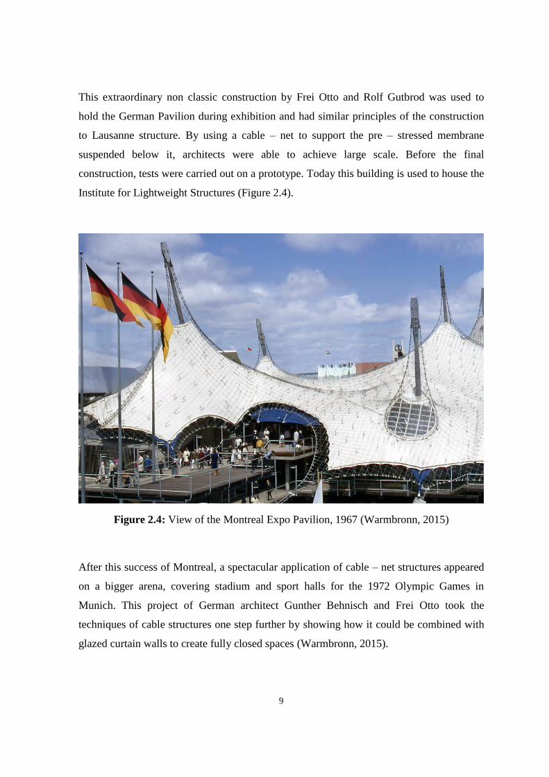
Clamped edge’s (Figure 3.7) clamping section is consisted of a boltrope, connected
through fixed or controllable connecting elements as turnbuckles.
Figure 3.7: Clamped corner edge element (Schock, 1997)
For the connection of cables and the rigid facade walls construction elements called aprons
are used. They are not pre – stressed and kept on the edge of the wall by the mean of
clamping strips and overshoot it. Welded aprons are hardly used because they cause
exfoliation which is perpendicular to the joint. For this case a seal with a foam rubber
bulge is applicable.
To create a double curvature in cable structure a series of ridge and valley cables is
operating parallel in the system (Figure 3.8). To have a good tension cables have a
controllable length. Ridge and valley cables are placed directly onto the roof covering
material. Some special devices for pre – stressing are used to flatten production
admittance.

27
Figure 3.8: Valley and ridge cables (Wright, 2010)
Cables used to facilitate loads at stress point are called eye loops or eye cables (Wright,
2010). Large eyes are made similar to cable edge. Their dense curvature may cause some
problems during the construction. However, small eyes and rosettes are difficult to be
produced.
A series of loops that used within the cover material plane to decrease stresses are called a
“butterfly” (Figure 3.9). They are very expensive details. At the connection points of cable
loops all loads are coming together and being transferred to foundation. One regular cable
loop can relieve the loads more combined with the “butterflies”. Sometimes they are also
used together with waterproof material.
Figure 3.9: Butterfly loops (Wright, 2010)
To control stresses in fabric materials at minimum and maximum points, details called bale
rings are used (Figure 3.10). At the high points they should be covered by waterproof

28
materials to avoid corrosion. Used at low points, they can collect and reallocate melting
snow and rain water (Wright, 2010).
High point rings are suspended by the mean of short cables connected to primary structure.
High point rings can be covered by steel boiler bottoms made as prefabricated steel
components, structures of glass – fiber reinforced polyester resin (GRB) or light domes,
polycarbonate or etc. They are produced by cutting method, pre – stressed and fixed by
special devices (Schock, 1997).
Figure 3.10: Bale rings (Wright, 2010)
Guys are solid bars or cables, their tensile forces are transmitted through steel parts to the
foundations, piles or anchors. It’s also possible to use guys without mast structures. The
guy force flows in the summary direction of two cables and the inherent point on the
ground is usually located far away. This limits the application of the guys needed quite big
space.
Loads, edge cables and edge webs are assembled at the roof structure’s corners and
involved into corner plate which is a part of the base.
Corner plates can be introduced in a several ways: at an open membrane corner, the roof
material is cut back, edge cables and nets are linked to the plate; the corner plate is pinched
to the fabric from up and down in the case of closed corners (Schock, 1997).

29
Types of the corner plates according to the B. N. Wright (2010) shown in Figure 3.11:
Corner plate with separately fixed cables;
Corner plate pinched to the fabric with fixed cables;
Corner plate with keder edge where cables have adjustable length;
Corner plate with specified connection belts.
Figure 3.11: Types of the corner plates (Wright, 2010)
3.3 Anchorage System
Anchorage system is used for the direct transfer of the loads to the ground. This system can
be used for all types of the cables structures. Variations of the anchorage depends on the
ground conditions of the construction site.
The most used types are (Figure 3.12):
Gravity anchors;
Plate anchors;
Mushroom anchors;
Retaining wall anchor;
Ground anchors;
Tension piles.

30
Figure 3.12: Types of the anchorage systems (Goldsmith, 2000)
Gravity anchorage working principle is to neutralize the vertical constituent element of the
loads with the help of its own weight. The horizontal compound is transferred to the
ground. Gravity anchorage is used in week soils like sand and gravel. They are massive
and heavy. Plate and mushroom types of anchorage systems lean on the soil abilities to
resist the loads from cables. They are used in the compacted soils like clay. Ground
anchorage transfers the horizontal compound of force by the weight of soil and vertical by
the shear force among ground and anchor. It is used in the granulated or clay types of soil.
Working principle of the tension piles is similar to the ground anchorage but the horizontal
compound is balanced by the confrontation of the pile and ground with the opposite
direction of the force (Goldsmith, 2000).
3.4 Classification of Cable Structures
By the load – transfer specification three main classes of cable structures can be presented:
Catenary typed structures where the main load transfer character is the axial
tension. Balance of the structure is gained by the compression beard by the

31
anchoring system or primary supports. The structure is not free – standing. In this
case, load is transported to the borders directly. Cable suspended structures are the
examples of catenary types.
Arch typed structures where the main load transfer character is the axle
compression. Loads are corresponded by the structural supports in this kind. Arch –
liked structures can stand freely under own weight but the deformation and self –
weight will be greater. Examples of these types are cancellated cable structures.
Mast types, in which load transfer pattern is the tension. The structure can be free
standing usually inclined for maximizing the ability of resisting the axial forces.
3.4.1 Catenary types or Saddle roof
Cables are the basic structural members because of their dominant supporting tensional
forces. The most famous of its types are catenary structures (Figure 3.13) with several
kinds discussed below.
Figure 3.13: Catenary – like types of the cable structures (Bing, 2004)
Cable net forms
In cable nets cables are acting as structural members. Saddle shape of it designed to solve
water drainage problem and pre – stress the system. Cable net forms are used in glass
curtain walling as well.
Cable stayed forms
Cable stayed forms (Figure 3.14) can be linear or circular way. Linear cable stayed forms
have hence units of base. The example of this type of structures if Denver International

32
Airport (United States of America). It is approximately 90 m by 300 m in structure
supported by 30 m long 34 masts (Bing, 2004).
Figure 3.14: Types of cable – stayed forms (Bing, 2004)
Circular cable stayed forms have the radial pattern of base units. Example of this type of
cable arrangement can be Millennium Dome (United Kingdom) which covers 80000 m².
Its 12 huge masts support long 150 m from the perimeter to the center cables (Bing, 2004).
Strut cable net forms
Isolated struts in these forms are set into cable net to organize the external curved surface.
So called spoke – wheel domes or cable girders and cable domes are the types of the strut
cable net forms.
Strut cable net forms usually act as trusses. They can be constructed in a different shapes
and forms.
Figure 3.15: Types of strut cable net forms (Bing, 2004)

33
Cable domes are relatively new types of construction. They are made of ridge cables,
diagonal cables, hoop cables and vertical struts.
Cable domes have 3 types: Geiger’s dome and spatially triangulated domes circular or
elliptical formed shown in Figure 3.15. In the first type, cable trusses are arranged forming
a circle. For example, structures of Gymnastic Arenas of 1986 Korean Olympic Games.
In the spatially triangulated dome rings of struts are displaced in a distance of half a unit.
The Georgia Dome in Figure 3.16 (240 m in length by 193 m in width) is rare example of
this type. In this building truss is linking two focuses with the weight 30 kg/m² (Bing,
2004).
Figure 3.16: The Georgia Dome stadium in Atlanta (Tucker, 2013)
Girders can be used to cover all space. One of girders variations, included big opening at
the center, called cable wheel form. Its example, Stadium Roof of National Sport Complex
in Kuala Lumpur. Sometimes spoke – wheel types are used in the glass supporting
structures with the massive facade.
3.4.2 Arch types
Cables sometimes used as reinforcing or stabilizing members in arch – like structures
because of the ability to support compression. Cables can enhance hardness and load
spread, minimize impulse of the supporting system. One of the examples when cables are
introduced to the arch directly is the dome in the University of Northern Iowa.

34
Cables are integrated with arched constructions because arch can support dimensions of
large and high structures. The curvature of arch is the good form for producing double –
curved cable structure like it showed in Figure 3.17. The Brand hangar can be the example
of arched forms of cable structures.
The vertical or so called standing arches are elaborated from a catenary chain and have
some disadvantages compared to catenary. Good form of the structure is applicable only by
specific loads. Dead load and snow loads are playing a huge role in formation of the
system while other loads (e.g. one – sided snow or wind loads) can cause bending of the
arch.
Cables are elastic so they can take a shape of various states of forces. It means that big
changes of shape are possible and limited only by constructional and functional facts.
Figure 3.17: Arch – like type (Bing, 2004)
Compression forces applied to the arch formed structure should be stabilized because arch
can change the position on the imaginary line or buckle at some angles to the plane. To
solve this problem arch should be stabilized by the fixed tensile fabric and cables structures
like it was done in the Gottlieb Daimler Stadium in Stuttgart.
The arch was manufactured very elastic while the tensile fabric is very rigid. It protects
whole structure from deformation and activates the stabilization from damaging the
structural members.

35
Figure 3.18: Brand – Briesen Airfield (Behrends, 2015)
Arch structures can be braced by cable nets as in the skating rink of the Olympic Park
(Munich, Germany). There great spans are achieved by the use of rigid cable webbing.
Rigid arch formed structures’ steadiness can be increased by the mean of side bracing
elements as was done in Brand hangar (Figure 3.18). Bracing elements are designed as
simple geometric forms and used to adjoin arches and transfer lateral stiffness from arch’s
deflection from the main axe. Bracing elements in the plane of the main supporting system
infringe above the arch. To resist buckling and bending of arched system it is necessary to
obtain proper load – bearing capacity and admit sufficient bending capacity.
3.4.3 Mast types
Masts are very popular types of primary structures in cable systems. It is easier to create
double – curved surface by raising structure by the use of masts higher than necessary by
function.
The Millennium Dome in London, United Kingdom (Figure 3.19) is the example of mast
types. The cable – net formed dome structure has a ring of 12 masts with hinged fixings
stayed outside in a circular way.

36
Figure 3.19: The Millennium Dome, UK (Macdonald, 2001)
Koch (2004) classified mast systems into following three classes:
Masts with hinged fixings and cable stays (Millennium Dome in London, United
Kingdom; swimming pool in Kuala Lumpur, Malaysia);
Masts with hinged fixings stabilized by roof fabric (BMW trade fair stand in
Frankfurt, Germany);
Masts with rigid fixings (Haj Terminal in Jeddah, Saudi Arabia).
Lateral forces on the mast influent the moments of resistance at the base of the masts if the
rigid fixings located too high because strong loads occur there. The design is breaking the
moment into a polygon of tension and compression forces with broad feet (Koch, 2004).
There are three types of masts used worldwide: flying, interior and exterior. The exterior
masts are suspended at height (Olympic Estate, Munich). The peak can be seen at the top
instead of the joint between the maximum point and pendant. The interior and flying masts
are basically the same since they support the high points of structure.
There are different ways of creation of high point. First is pushing against the continuous
fabric from the bottom. Shaped point which can be seen as soft is actually a fluent and

37
smooth form as the Imagination Building in London, United Kingdom. The structure must
be reinforced. The seam lines are passing around the maximum point with the regular
character.
Second way of making a point at the top is a ring. Its vertex edge is forming a conical
shape, reinforced as the seam lines in a radial order, concentrated at the top of the cone and
the ring support. Example of this high point creation is the Grande Arche in Puteaux,
France (Scheuermann and Boxer, 1996).
The third variation is analogous to the second type. But here the mast passes through the
radial opening at the top of the cone and returns to a small cables suspension point of the
cone. These small cables collect the loads and transmit to the top of the mast. Radial
pattern of the cutting causes a strong connection of the high point which is the center of the
seam lines focus.
Bottom supports differentiate interior and flying masts. The interior mast transfers the
loads in compression form from the up downwards to the foundation. The flying mast
carries the compression to the cables which transmit the load to support points of the
structure. Both types are creating wide column – free spaces beneath. Flying masts can be
designed like an attractive detail with a good perception.
Stayed masts can withstand high loads. But additional stresses may occur as a result of
wind loads and the dead loads of the masts in compression.
The masts are potentially endangered in their stability or buckling, because the axial forces
increase the moment stresses from the outer forces and minuses of geometric shape. So
why sometimes masts are changed by anchored by means multiple stays or grid structures.
Regarding it they have bigger resistance to instability. During the system pre – tensioning
compression can be amplified in the central tube in the case of closed system.
Tubular masts with conical base and a cylindrical middle part economical and good –
looking solving of aesthetical problem in large scale structures. Their structural behavior is
represented in nominal shape.

38
Masts located within the fabric structures and not anchored to the foundation base are
made with a spherical seating at the ground. Large deformation may occur in different
loading within neighboring bays.
When a rotation in excess of about 2º occurs, the spherical bearings have to change from a
rolling to a sliding motion. Whereas a rolling movement poses no special problems for the
surface finish and treatment, sliding bearings have to be very carefully worked and fitted
out to ensure a low degree of friction. It can seriously affect the sizes of whole structure
(Koch, 2004). Rigid fixed masts are difficult to admit. They should be free of dead load
and pre – stress moments. Small deviations in different degrees may result bending of the
system.
3.5 Assembly of the Primary Structural Support
The assembly of large scale primary support is based on the construction of bridge –
building and its erection. Large building members need to be lifted and sometimes the
lifting machine is not available or access to the site is too difficult.
Cable structures are easier to be erected and less power will need. They can be rolled up
for transportation and be laid on the ground in precise form.
There are two methods of assembly of large scale cable structures supports: the erection of
tall masts and assembly of spoked – wheel structures. Many factors play role in this
construction process. So safety level should be very high at the construction site and
transportation of the structural parts and members should be done with all technical
regulations.
3.5.1 Tall masts assembly
Masts represent linear high structural steel members used to keep the fabric roof and cable
net together. They are frequently anchored to the foundations with hinged base (Wright,
2010).
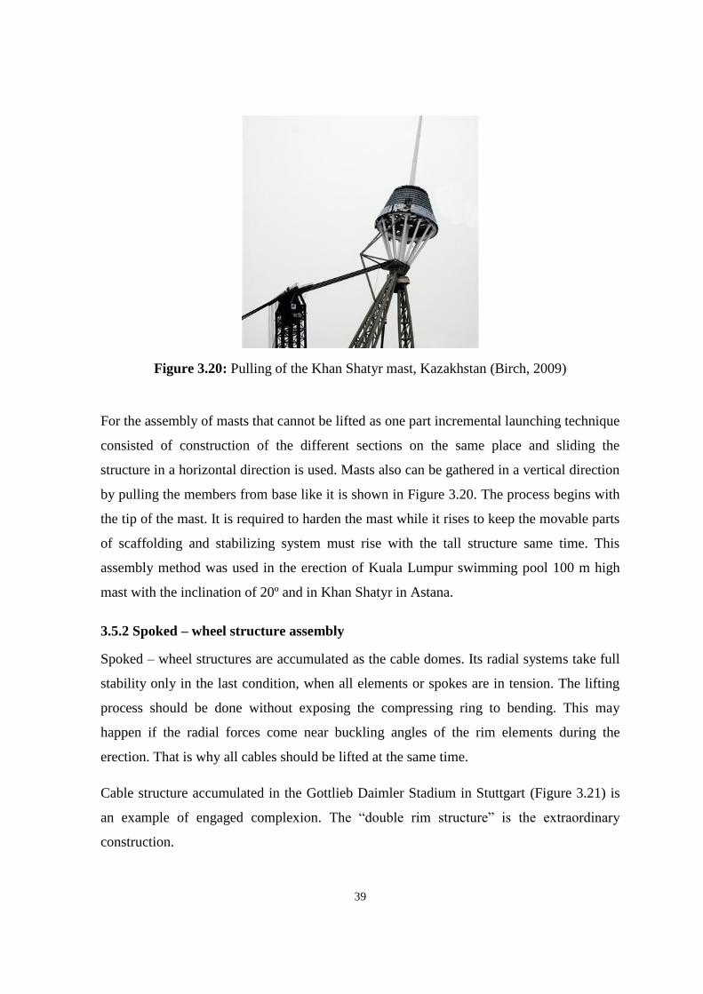
39
Figure 3.20: Pulling of the Khan Shatyr mast, Kazakhstan (Birch, 2009)
For the assembly of masts that cannot be lifted as one part incremental launching technique
consisted of construction of the different sections on the same place and sliding the
structure in a horizontal direction is used. Masts also can be gathered in a vertical direction
by pulling the members from base like it is shown in Figure 3.20. The process begins with
the tip of the mast. It is required to harden the mast while it rises to keep the movable parts
of scaffolding and stabilizing system must rise with the tall structure same time. This
assembly method was used in the erection of Kuala Lumpur swimming pool 100 m high
mast with the inclination of 20º and in Khan Shatyr in Astana.
3.5.2 Spoked – wheel structure assembly
Spoked – wheel structures are accumulated as the cable domes. Its radial systems take full
stability only in the last condition, when all elements or spokes are in tension. The lifting
process should be done without exposing the compressing ring to bending. This may
happen if the radial forces come near buckling angles of the rim elements during the
erection. That is why all cables should be lifted at the same time.
Cable structure accumulated in the Gottlieb Daimler Stadium in Stuttgart (Figure 3.21) is
an example of engaged complexion. The “double rim structure” is the extraordinary
construction.

40
Figure 3.21: The Gottlieb Daimler Stadium, Germany (Nunninghoff, 2003)
In the end of the construction process the cables had laid out in a way that the cable ring
system and nodes are connected in their right positions. After the radial cables should be
fixed to the inner ring and suspension cables connected to form trusses. The upper cables
are connected to the points where the stranded hoisting wires and hydraulic cylinders are
set. The cables should be elaborated outside so the whole cable system will rise. In the end
all upper cables will come to their final place. The ultimate tension of the cable structural
system may be obtained by the process of stressing of the low simultaneously.
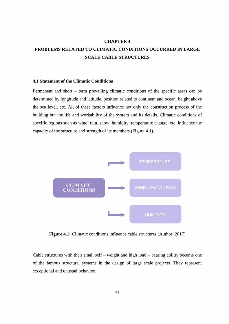
41
CHAPTER 4
PROBLEMS RELATED TO CLIMATIC CONDITIONS OCCURRED IN LARGE
SCALE CABLE STRUCTURES
4.1 Statement of the Climatic Conditions
Permanent and short – term prevailing climatic conditions of the specific areas can be
determined by longitude and latitude, position related to continent and ocean, height above
the sea level, etc. All of these factors influence not only the construction process of the
building but the life and workability of the system and its details. Climatic conditions of
specific regions such as wind, rain, snow, humidity, temperature change, etc. influence the
capacity of the structure and strength of its members (Figure 4.1).
Figure 4.1: Climatic conditions influence cable structures (Author, 2017)
Cable structures with their small self – weight and high load – bearing ability became one
of the famous structural systems in the design of large scale projects. They represent
exceptional and unusual behavior.

42
Cables under the loads caused by climatic peculiarities undergo some deformation, with
the change of load configuration the form of the cable changes as well. Details distortions
increase the risk of the structure collapse, reduce structure lifetime and decline significant
value. The tension appeared in the cable supports and its displacement under the outer
impact affects the total stability of a structure. To decrease the impact of the nonlinear
properties the cables are going through the pre – stretch. Optimal values for it can be found
from the stress – strain diagram shown in Figure 4.2.
Figure 4.2: Curve of the stress – strain dependence (Gossen, 2004)
The standards for the cable structures are specified in the book called ASCE 19 – 96. It
designates in the Figure 28 that the best modulus to stress – strain is between 10 % of
nominal strength and 90 % of pre – stretching load. But optimal value is considered as 50
% of nominal strength (Gossen, 2004).
One of the common actions appearing in cables due to their climatic response is floating or
the differences in sagging which is consequence of the cable strains movement. It directly
influences the load – bearing ability of the structure.

43
Cable structures are found to be well resisted to the fire. With the rise of the temperature
pre – stressed steel cables remit and the tension of the members decreases gradually. It
allows the whole structure of the roof decay slowly and not simultaneously. By the time
the strength of cables becomes weakened all the loads and forces are ended up owing to
cables pre – tension. This process leads to the growth of the safety factor over structure
collapse at the beginning of fire (Vanderberg, 1998).
Flexibility and light weight of cables and structural members gives the good possibility of
cable systems to be built in high seismic zones. Cable systems built in hot climate have an
additional effect of “cooling tower” which can be very useful and advantageous. Tent form
of the building also works in a way that air cooled in the night may be kept for the use over
the following daytime.
4.2 Factor of Safety for Cable Structures
“Factor of safety” applied to the whole structure and its separate members points the
working stress design (WSD) relation. In WSD deformation, stress and force are accepted
as linear quantities.
Factor of safety is used to define the defects in sudden overloading, mistakes due to
materials choice and manufacturing process. So the values of insignificant strength of the
cable needed for the proper work of the system will be defined. But because of the
structures non – linear behavior this factor range can be very wide and to detect it special
trials under the service load should be done.
Principles of resistance and load factored design can be used for prevention of future
construction collapse. In it failure can be found at the level of ultimate load. Resistance
factor directly affects the strength of material and production deflections. The complexity
of cable structural system requires the extensive methods of analysis. It is designated by
the estimation of pre – stressed cables (Gossen, 2004).
4.3 Vibration due to Temperature Change
Low fading of cables causes vibration problems of the system. It can be summoned by
traffic, earthquake, rain/snow/wind effects or temperature fluctuations.
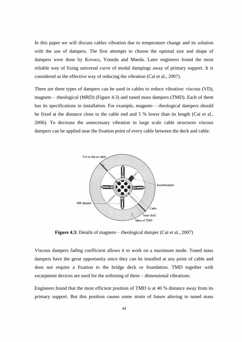
44
In this paper we will discuss cables vibration due to temperature change and its solution
with the use of dampers. The first attempts to choose the optimal size and shape of
dampers were done by Kovacs, Yoneda and Maeda. Later engineers found the most
reliable way of fixing universal curve of modal dampings away of primary support. It is
considered as the effective way of reducing the vibration (Cai et al., 2007).
There are three types of dampers can be used in cables to reduce vibration: viscous (VD),
magneto – rheological (MRD) (Figure 4.3) and tuned mass dampers (TMD). Each of them
has its specifications in installation. For example, magneto – rheological dampers should
be fixed at the distance close to the cable end and 5 % lower than its length (Cai et al.,
2006). To decrease the unnecessary vibration in large scale cable structures viscous
dampers can be applied near the fixation point of every cable between the deck and cable.
Figure 4.3: Details of magneto – rheological damper (Cai et al., 2007)
Viscous dampers fading coefficient allows it to work on a maximum mode. Tuned mass
dampers have the great opportunity since they can be installed at any point of cable and
does not require a fixation to the bridge deck or foundation. TMD together with
escarpment devices are used for the softening of three – dimensional vibrations.
Engineers found that the most efficient position of TMD is at 40 % distance away from its
primary support. But this position causes some strain of future altering to tuned mass

45
dampers. TMD with proportional to acceleration inerter and fixed at the ambit of cable
support is used for the reduction of cables vibration (Webster and Vaicaitis, 2003).
Vibration health monitoring (VHM) can be used for the check of weakening of the cables,
sagging of the bars and the maintenance of structure. VHM uses the innate periodicity and
mode forms as sensitive to damage features.
A tensile axial force increases intersecting rigidity which affects the vibration properties.
Meanwhile the growth of the compressive forces in bars reducts the intersecting near to
buckling. Slacking cables decrease the stiffness and frequencies, and degrade natural
vibration. VHM considers the nonlinearity of the cable structures distinguished in the
coupling among the bending and axial rigidity of members. Pre – stress template, degree,
aim of the best rigidity value constitute the element base of VHM.
To use the VHM pre – measurement analysis should be done in advance. Pre –
measurement analysis consist of two stages selection of vibration excitation and pointing
of sensors. The goal of this measurement is to determine one excitation point for further
choosing of sensor point on specified diapason of frequencies.
Some of the pre – measurement methods treat only the sensor placements while others are
working with both excitation and sensor location. Methods based on kinetic energy,
eigenvector or effective independents are used for sensors integration and methods based
on point residues, eigenvector or kinetic energy are used for finding the excitation points
(Ashwear and Eriksson, 2016).
The basic parts of pre – measurement are vibration response analysis and modal analysis.
Modal analysis is the process of revelation the natural periodicity, the form of the structure
and damping factors. It is based on the mass, rigidity and damping of the system.
During the pre – measurements process every vibration form is excited and measured from
special points to use one stimulation point for the forms of interest and certain sensor for
every form. It is necessary for finding a point with maximum amplitude over the selected
diapason (Lazar et al., 2016).

46
Vibration health monitoring is based on the variation in vibration properties of the
structure. These variations are caused by the damage or environmental conditions
(temperature, snow, wind, etc.). The can be caused are contingent on support properties,
scale and form of the structure, materials and pre – stress degree.
Fluctuations of temperature causing the vibration are related either to changing in the
modulus of elasticity or to the coefficient of thermal expansion. Changing in the length of
cables and bars occurs same time and the degree of pre – stress (Ashwear and Eriksson,
2016).
Rise of the bars unstressed lengths enlarge the degree of pre – stress but rise of the lengths
of cables deducts it. The response of the structural system to simultaneous temperature
change can be separated to cable dominated and bar dominated vibrations. The pre – stress
degree template degree is basic parameter affecting the rigidity and strength of cable
structure. During the VHM process it is necessary to pay attention to the damage detection
and damage localization. First shows how the design differs from the existing structure,
second where the retrogration took a place (Ashwear and Eriksson, 2016).
4.4 Dynamic Effect of Wind
Fluttering or aero dynamical instability is one of the most important problems in large
scale cable structures. This assesses special demands in the design and the construction of
the building.
Main determinative factors are the necessity of the rigidity under transverse loads and
anchorage to foundation.
Single cables need to be stiffened to avoid the shape modifications and to increase the
resistance uplift. Stormy wind can create fluctuations if damping is not accommodated to
the construction (Vanderberg, 1998).
There are some ways to prevent fluttering of cables: rise the dead load on the roof, anchor
guy cables to connect the structure on the ground (Figure 4.4) and use crossed cables on
double cable system.

47
Figure 4.4: Cable structure’s anchorage system (Wright, 2010)
Basic methods for providing stability:
Additional load supported on the roof used to balance the effects of asymmetrical
actions;
Adding of mass (e.g., concrete slab) helps to stabilize the roof structure but same
time increases the weight of it;
Beams – like rigid members where constant load may not be strong enough to
neutralize uplift load fully but at sufficient bending stiffness to deal with this load
and allow cables to resist the gravity;
Compression of hard structure resists the uplift forces on rigid surface;
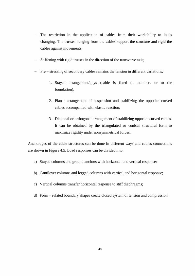
48
The restriction in the application of cables from their workability to loads
changing. The trusses hanging from the cables support the structure and rigid the
cables against movements;
Stiffening with rigid trusses in the direction of the transverse axis;
Pre – stressing of secondary cables remains the tension in different variations:
1. Stayed arrangement/guys (cable is fixed to members or to the
foundation);
2. Planar arrangement of suspension and stabilizing the opposite curved
cables accompanied with elastic reaction;
3. Diagonal or orthogonal arrangement of stabilizing opposite curved cables.
It can be obtained by the triangulated or conical structural form to
maximize rigidity under nonsymmetrical forces.
Anchorages of the cable structures can be done in different ways and cables connections
are shown in Figure 4.5. Load responses can be divided into:
a) Stayed columns and ground anchors with horizontal and vertical response;
b) Cantilever columns and legged columns with vertical and horizontal response;
c) Vertical columns transfer horizontal response to stiff diaphragms;
d) Form – related boundary shapes create closed system of tension and compression.
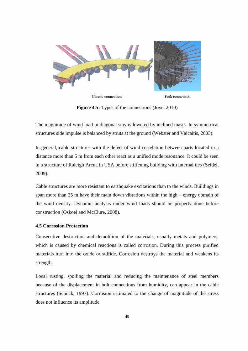
49
Figure 4.5: Types of the connections (Joye, 2010)
The magnitude of wind load in diagonal stay is lowered by inclined masts. In symmetrical
structures side impulse is balanced by struts at the ground (Webster and Vaicaitis, 2003).
In general, cable structures with the defect of wind correlation between parts located in a
distance more than 5 m from each other react as a unified mode resonance. It could be seen
in a structure of Raleigh Arena in USA before stiffening building with internal ties (Seidel,
2009).
Cable structures are more resistant to earthquake excitations than to the winds. Buildings in
span more than 25 m have their main down vibrations within the high – energy domain of
the wind density. Dynamic analysis under wind loads should be properly done before
construction (Oskoei and McClure, 2008).
4.5 Corrosion Protection
Consecutive destruction and demolition of the materials, usually metals and polymers,
which is caused by chemical reactions is called corrosion. During this process purified
materials turn into the oxide or sulfide. Corrosion destroys the material and weakens its
strength.
Local rusting, spoiling the material and reducing the maintenance of steel members
because of the displacement in bolt connections from humidity, can appear in the cable
structures (Schock, 1997). Corrosion estimated to the change of magnitude of the stress
does not influence its amplitude.
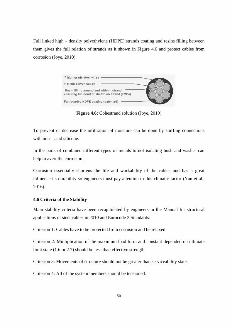
50
Full linked high – density polyethylene (HDPE) strands coating and resins filling between
them gives the full relation of strands as it shown in Figure 4.6 and protect cables from
corrosion (Joye, 2010).
Figure 4.6: Cohestrand solution (Joye, 2010)
To prevent or decrease the infiltration of moisture can be done by stuffing connections
with non – acid silicone.
In the parts of combined different types of metals tufnol isolating bush and washer can
help to avert the corrosion.
Corrosion essentially shortens the life and workability of the cables and has a great
influence its durability so engineers must pay attention to this climatic factor (Yan et al.,
2016).
4.6 Criteria of the Stability
Main stability criteria have been recapitulated by engineers in the Manual for structural
applications of steel cables in 2010 and Eurocode 3 Standards:
Criterion 1: Cables have to be protected from corrosion and be relaxed.
Criterion 2: Multiplication of the maximum load form and constant depended on ultimate
limit state (1.6 or 2.7) should be less than effective strength.
Criterion 3: Movements of structure should not be greater than serviceability state.
Criterion 4: All of the system members should be tensioned.

51
Criterion 5: Resonance of the structure due to dynamic loads such as wind, traffic,
earthquake, etc. should be evaded (Aćić et al., 2013).
Methods can be used for stabilization of cable structure are shown in Figure 4.7.
Figure 4.7: Example of stabilizing system in the New Deli Stadium (Joye, 2010)
4.6.1 Pre – tension of cables
Deflections of the structure’s shape represent the first problem in cable system. To keep
the form under the applied loads the process of pre – tension is used which sustain the
deformation of the cables in given bound. Special software is used to select the appropriate
forms. To improve the cables conduct because of the sag strain the pre – tension is applied.
Axial tension gives the ability to withstand the displacement of endings and its primary
tension is kept in the compression content. So when the cables deprive pre – tensioning
they do not support the structure in its stiffness and durability.
Guys are originally pre – tensioned members of cable structural system show that pre –
tension is actually a property of the building. Mast supports the guys from vertical forces.
The force in the downwind guy falls and the force in the upwind guy rise, while staying
unaltered in the support. Loss of pre – tension may cause the changes of forces in members
and precipitate the behavior of a structure.
One of the ways to pre – tension the cables to minimize its disfiguration is the jacking of
cable net. The process of jacking starts from applying small increasing loads to the

52
structure. At every stage the loads and their impact specify the foundation of the model.
This manipulation is recurred till the absolute amount of loads is reached. If during this
procedure some cables are weakened they are disposed from the structural system and if it
takes tension back the software recovers the cable again. After the construction using this
model of pre – tensioning, cables will not lose its tension even by high loads. Nodes used
in the software crop the force behavior in the cable net and designate the local distortion.
When tensioned cable is used in axle direction to increase tension, the reaction is almost
linear because of the pre – stress degree. If the cable in tension is perpendicularly loaded,
forces are in direct function as its original tension (Gossen, 2004).
4.6.2 Pre – stressing devices
Pre – stressing is used for the increasing the resistance to outer forces by creation of state
of co – action of tension and deformation. This process involves the usage of special
devices. Most famous are left – and right – hand threaded solid bars used as ties. They are
twirled into a female thread and turned tie at the joint or by usage of a turnbuckle sleeve.
Another type of pre – stressing device is a cable with steel connection element at the
ending (end fitting). It is used as threaded ending or fork. Pre – stressing devices are shown
in Figure 4.8.
Figure 4.8: Types of the girders (Aćić et al., 2013)

53
For the pre – stress of single cable the anchorage with threaded bars foundation is set on a
steel ledger. Bars are grounded by nuts or counter nuts. At the middle of a ledger guy cable
can be secured by a steel component fixed at the end of a cable.
To minimize the permissible variation in the spacing between the bolts anchor screws are
supplied with the cast mold. Pre – stress forbearance is initiated at mortar joints and angle
forbearance at the bolts (Schock, 1997).
Kinds of pre –stressing activities done in the cable structures:
Abbreviated aerial ties;
Masts raised by the usage or rings;
Jacked up flying masts;
Straight edges pulled out over a stiff pale or to immediate pre – stressed cable;
Pulled to a closed pale scalloped cable edge;
Truncated toggle elements at the spike points of cable edge (Koch, 2004).
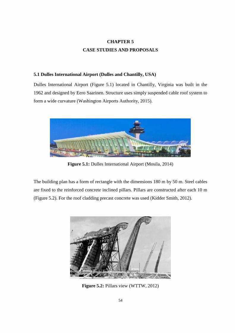
54
CHAPTER 5
CASE STUDIES AND PROPOSALS
5.1 Dulles International Airport (Dulles and Chantilly, USA)
Dulles International Airport (Figure 5.1) located in Chantilly, Virginia was built in the
1962 and designed by Eero Saarinen. Structure uses simply suspended cable roof system to
form a wide curvature (Washington Airports Authority, 2015).
Figure 5.1: Dulles International Airport (Mosila, 2014)
The building plan has a form of rectangle with the dimensions 180 m by 50 m. Steel cables
are fixed to the reinforced concrete inclined pillars. Pillars are constructed after each 10 m
(Figure 5.2). For the roof cladding precast concrete was used (Kidder Smith, 2012).
Figure 5.2: Pillars view (WTTW, 2012)

55
Since the shed has a catenary – like shape wrong water drainage system could cause
structural problems and collapse. Engineers run lengthwise ocarina form gully in the center
of the roof to collect the water. Section and system details are shown in Figure 5.3 below.
Figure 5.3: System details (WTTW, 2012)
Steel cables (Figure 5.4) carry the vertical loads applied to the building. In the stressed
mode they induce the forces to the angled structural columns. Columns neutralize the
moment of horizontal drag of the dead load. All vertical forces are transmitted to the
ground by pillars to hard concrete beneath. Pillars have widened base to have more
resistance to bending moment. Hardness of the concrete slabs protect Dallas International
Airport from horizontal deviations (Kidder Smith, 2012).

56
Figure 5.4: Placing of cables (WTTW, 2012)
The cable structural system used in this project gives a wide column – free space (Figure
5.5) so much needed in airport construction from one side and provides a lightness and
aesthetic from another. Cables used to form the roof same time play the role of
reinforcement. Thereby the structure became more stable to dynamic loads such as wind
influence and snow bearing capacity was increased.
Figure 5.5: Interior view (Kidder Smith, 2012)

57
5.2 Burgo Paper Mill (Mantua, Italy)
Burgo Paper Mill (Figure 5.6) or Cartiera Burgo was designed by Pier Luigi Nervi and
built in 1963. It is self – anchored cable – suspended structure used for the production of
paper. Mill is still working and stands as the gates to the Mantua city in Lombardy, Italy
(Iori, 2009).
Figure 5.6: Burgo Paper Mill (Burgo, 2014)
Reinforced concrete base forms the nave structure on two levels to support the production
systems. Nave has the dimensions of 25 m long, 30 m wide and 15 m high. Self – anchored
roof is consisted of 4 piers produced from reinforced concrete, 12 steel catenaries and 48
cables. The base of the piers is a lambda formed slanted compressed strut. Its peak reaches
the 47 m height (Figure 5.7). Struts were mounted across by girders with a steel core.
Girders with the dimensions are 6 m in the base and 6 m tall have the place for the
polygonal catenaries produced from the steel bars. Roof is raised at a height of 22 meters.
It consists of a steel deck suspended by four steel cables and two side cantilevers.
Cantilevers have a height about 43 m. Cables of the structure have the diameter of 45 mm
and they are arranged in 10 m distance from each other. Steel cables keep the lengthwise
girders if the roof. Glass facade is binded with steel passes between the roof and the base
till the end of the mill. All vertical consoles slabbed at the base established an illusion of
reversed curtain wall (Allen and Zalewski, 1998).

58
Figure 5.7: Building under construction (Burgo, 2014)
With this appearance building shell is looking separated and independent from its roof.
Two part or the Burgo Paper Mill: shell production hall and suspended roof have the
ability to act separately under the loads without endanger their structure. Connection
between two parts was influenced by the climatic conditions such as an effect of thermal
bridge and required special precautions. The pillars of the mill have the height of 13.5 m
and width 25 cm. They were supplied at 1.5 m from the center point and helped to resist
big winds. All rainwater pipes are fixed at the distance of 4.5 m from the center. For the
roof cladding Pier Luigi Nervi chose the steel (Allen and Zalewski, 1998).
Ordering of the prefabricated system details helped the architect to decrease the total price
of the Burgo Mill. These parts were placed into reinforced concrete produced in different
60 variations. Prefabricated pieces were assembled together with stiffed pillars.
Burgo Paper Mill is the good example of innovative design and technologies. Structure in
its pure form attracts presents oneself a symbolic structure of the Mantua.

59
5.3 Olympic Gymnastics Oval (Seoul, Korea)
The Gymnastics Arenas for the Korean Olympic Games (Figure 5.8) was designed by Kim
Swoo – Geun and built in 1986. Structure represents a circular cable dome with the radius
nearly 120 m. Engineer of Gymnastics Arena David Geiger used an idea of Fuller's dome
and throw off the abundancies in Fuller's triangulated spatial form to achieve static
qualifier. Geiger simplified the structure for easier future construction (Korea Times,
2013).
Figure 5.8: Olympic Gymnastics Arena in Seoul (Rastorfer, 1988)
Tension cables and compression pillars form the dome roof. Radial ridge cables pass
among the orbicular compression and centric tension rings to transmit the loads applied to
the roof with the help of hoop and intermediate cables and shrinkage struts. Struts and
cables come together at the centric ring. Details of the structure are shown in Figure 5.9
below.

60
Figure 5.9: System details (Rastorfer, 1988)
When walls of the arena were built the process of dome construction had begun. 16 radial
cables were mounted to the centric tension ring, erected to the height and attached to the
concrete compression ring by the other endings. After that hoop cables and posts were
elevated and fixed to the castings of ridge cables. Cables passing from the supreme of the
ring to the base of the struts were tensed by dragging the hoop till the end (Figure 5.10).
Such pre – tensioning process required a simultaneous work and high responsibility. At the
last stage the fabric material was fastened by internal screw made of stainless steel to the
founding of ridge cables (Columbia University, 2004).

61
Figure 5.10: Dome installation (Rastorfer, 1988)
Four layers fabric was used for the roof material:
High – durability fiberglass fabric with a silicone coating;
Silky fiber glass;
Mylar insulation barrier;
Silicone coated acoustic pad.
Suchlike combination meets all the requirement for Korea’s climate during the whole year.
The fabric installation did not meet additional problems since the material was not
tensioned and was merely conjoint to the passing radially ridge cables (Columbia
University, 2004).

62
5.4 Denver International Airport (Denver, USA)
Denver International Airport (Figure 5.11) was opened for public in 1995 and designed by
Curtis Fentress Architects. It is considered as one of the world’s busiest terminals and best
airports of North America. Total area including 12 000 lots car parking and 84 gates is 53
square miles (Fentress Architects, 2016).
Figure 5.11: Denver International Airport (Fentress Architects, 2016)
Airport Great Hall roof is supported by steel masts arranged in two rows with a 45 m
periodicity. The height of the masts varies from 32 m to 39 m. 34 masts were covered with
fiberglass reinforced plastic hoods with different dimensions 1.8 m by 2.4 m and 3.6 m by
8.5 m (Figure 5.12). Weight of the masts, 16 km steel cables, 6 km aluminum clamps, 61
300 m² PTFE membrane is nearly 400 tons. It took 9 months of work to build a roof
structure (Barden, 2006).
Figure 5.12: Mast detail (Fentress Architects, 2016)

63
To carry the live loads and stabilize the masts ridge cables were flanged from the highest
peaks of the 17 masts pairs. They were placed in the way to be seen from outside. Valley
cables were fixed to tie the roof membrane and to resist uplift winds. To tension the
structure catenary cables were slung to the anchorage on the ground. All cables and
membrane were pre – tensed for better load resistance and shown in Figure 5.13 (Barden,
2006).
At the arrivals gates cable structure canopies provide a shelter from precipitations. This 12
m wide and 274 m long umbrellas have conical form (Barden, 2006).
Figure 5.13: Cables and membrane (Fentress Architects, 2016)
Computer modelling was completed to perform structural analysis of structure. Large
deviations method was used for planning of construction and system detailing.
At the beginning of construction process concrete floor slabs were made for the
approximately 11 500 kg live loads per m². Steel masts were prefabricated and erected with
the help of boom cranes. Welding and cordage works were done before the lifting process.
For the stabilization of system during construction engineers used temporary guy cables
which were replaced after. When the masts took its position cables were affixed and
formed the shape of the roof for future placing of membrane (Barden, 2006).

64
Truss rings on the top of the masts have oval form and were pre – casted in two parts.
Rings were placed around the mast base and scalded to each other. After that skylights
from the glass, lighting system and mast vertex pieces were mounted on the rings. Inside
view of the airport is shown in Figure 5.14.
Figure 5.14: View of the interior (Fentress Architects, 2016)
For the roof cladding architect choose white colored PTFE membrane which can resist
cold temperature and snow with the comparatively low coast. It reflects up to 75 % of sun
radiation and minimizes the heat level. Membrane was pinched to the valley cables at
nearby laurel wreaths. Zipper clamping sew together all the assembling elements. When
the clamps were fixed waterproof PTFE membrane was scalded into it (Barden, 2006).
Denver International Airport exemplifies perfect cable structure with the consideration of
climate influence and bears a resemblance of Colorado Rocky Mountains (Figure 5.15).
Figure 5.15: Denver International Airport cable roof (Fentress Architects, 2016)

65
5.5 Rhoen Clinic Medical Center (Bad Neustadt, Germany)
Rhoen Clinic (Figure 5.16) is the first glazed cable net structure used silicate glass and
built in 1997 in Bad Neustadt, Germany. It was designed by Lamm – Weber – Donath
Architects and Werner Sobek Engineers. The structure ensures a covered connection of
clinical buildings in medical center and its total area is approximately 1 800 m² (Werner
Sobek Ingenieure, 2004).
Figure 5.16: Rhoen Clinic project (Werner Sobek Ingenieure, 2004)
The main purpose was to create an extensive and light space without intervention to the
existed built environment. Steel cables were chosen as the best solution for the main
structural elements in this case. In Rhoen Clinic project cable nets (Figure 5.17) are
suspended on the masts from wood acting as a primary structural supports and covered
with silicate glass. Glass allows the structure to be fully transparent and use natural light
during the day (Campagno, 1999).

66
Figure 5.17: Cable net (Werner Sobek Ingenieure, 2004)
Cables forming the net have the diameters between 9.5 mm and 4.5 cm. Ring cables
banded the cable net produced from galvanized steel and fixed to wooden mast for the
compression. Guy cables allocated at the circumference are mounted to the ground directly
(Campagno, 1999). The curvature form of the structure was established with the help of
computer aided design using the form – finding methods. Computer modelling allows the
engineers check if all the parts of the cable net are in tension during the load – bearing
process for prevention of future collapse.
Figure 5.18: Silicate glass panels (Werner Sobek Ingenieure, 2004)

67
Silicate glass panels (Figure 5.18) cover the cable net and create a new system where
overlaid panels are connected to the cable net by clips. These clips are produced from
stainless steel and have standard dimensions while the net has different geometry. Such
system make the construction more economical since the process does not require the
production of specific glass sizes and facilitates the impact of green – house effect in
covered spaces. Fresh air can circulate in the holes left from the glass overlaying and same
time protects from the undesirable humidity and rain impact. Rhoen Clinic canopy – like
structure is very rough and steady against the high loads even during the winter (Werner
Sobek Ingenieure, 2004).

68
5.6 Jean – Marie Tjibaou Cultural Center (Noumea, New Caledonia / France)
The Jean – Marie Tjibaou Cultural Center (Figure 5.19) is a Kanak culture center built in
natural reserve of Noumea of New Caledonia by Renzo Piano. It was opened after 7 years
of construction in 1998. The Centre is a group of small pavilions and green areas placed on
the Tina Peninsula edged by three sides by water. The site lush vegetation is cut through
with trails and paths, amongst which there are villages – congestion of semicircular
structures among the pathway in tree – filled spaces.
Figure 5.19: View of the huts (Gordon, 2013)
The heart of the Center is the 8188 m² building made up of ten tall, ribbed steel structures,
reminiscent of the huts and spread over 230 m along a north-east and southwest arc. The
structure and functionality of the so – called huts are represented in circular plan cables
structures. Ten huts buildings have varied sizes from 20 to 28 m in height united by trail
and serving diverse functions. First group is the exhibition area, second – research areas,
library and conference hall. The last group of huts hosts studios for music, dance, sculpture
and painting.
All structures have effective passive ventilation system without usage of mechanical air
supplies. Air circulates among the layers of slatted wood through the double exterior
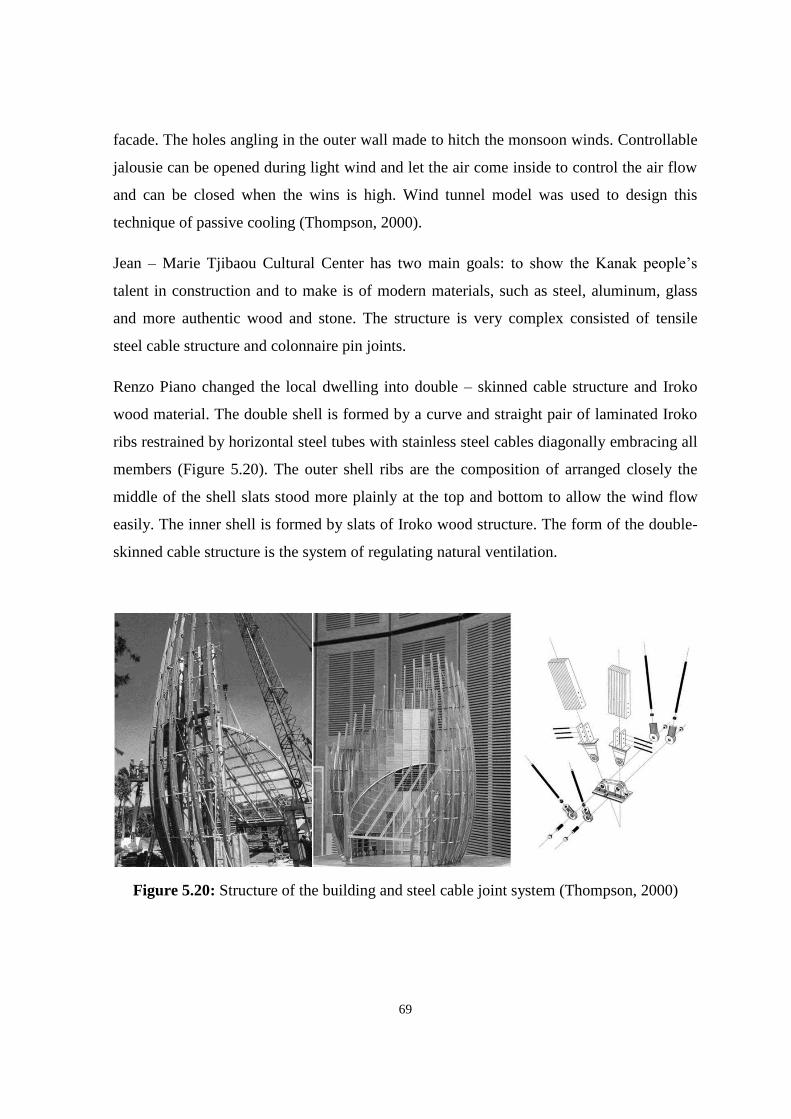
69
facade. The holes angling in the outer wall made to hitch the monsoon winds. Controllable
jalousie can be opened during light wind and let the air come inside to control the air flow
and can be closed when the wins is high. Wind tunnel model was used to design this
technique of passive cooling (Thompson, 2000).
Jean – Marie Tjibaou Cultural Center has two main goals: to show the Kanak people’s
talent in construction and to make is of modern materials, such as steel, aluminum, glass
and more authentic wood and stone. The structure is very complex consisted of tensile
steel cable structure and colonnaire pin joints.
Renzo Piano changed the local dwelling into double – skinned cable structure and Iroko
wood material. The double shell is formed by a curve and straight pair of laminated Iroko
ribs restrained by horizontal steel tubes with stainless steel cables diagonally embracing all
members (Figure 5.20). The outer shell ribs are the composition of arranged closely the
middle of the shell slats stood more plainly at the top and bottom to allow the wind flow
easily. The inner shell is formed by slats of Iroko wood structure. The form of the double-
skinned cable structure is the system of regulating natural ventilation.
Figure 5.20: Structure of the building and steel cable joint system (Thompson, 2000)

70
The cable structures (Figure 5.21) situated on the south side of the Cultural center allow its
vertical enlargement to shade the roof from direct sun rays and produce the heated air
between two levels of material which passes through the hollow. Jalousie can be regulated
to let wind form a negative pressure at the top of the roof while the wind is too strong
(Crawford, 2009).
Figure 5.21: Diagram of the cables arrangement (Irwin, 1999)
Made of wood iroko, the structures take with time the color of the trunks of coconut trees
that border the shores of New Caledonia and their cladding is made of stainless steel. For
the construction was used 300 m³ of wood and 5 tons of steel. The boxes combine the
techniques of the future, such as glulam, with traditional materials. Jean – Marie Tjibaou
Cultural Center with a total surface area of 8188 m² is located on 8 hectares in symbiosis
with the natural elements present on the peninsula (Thompson, 2000).
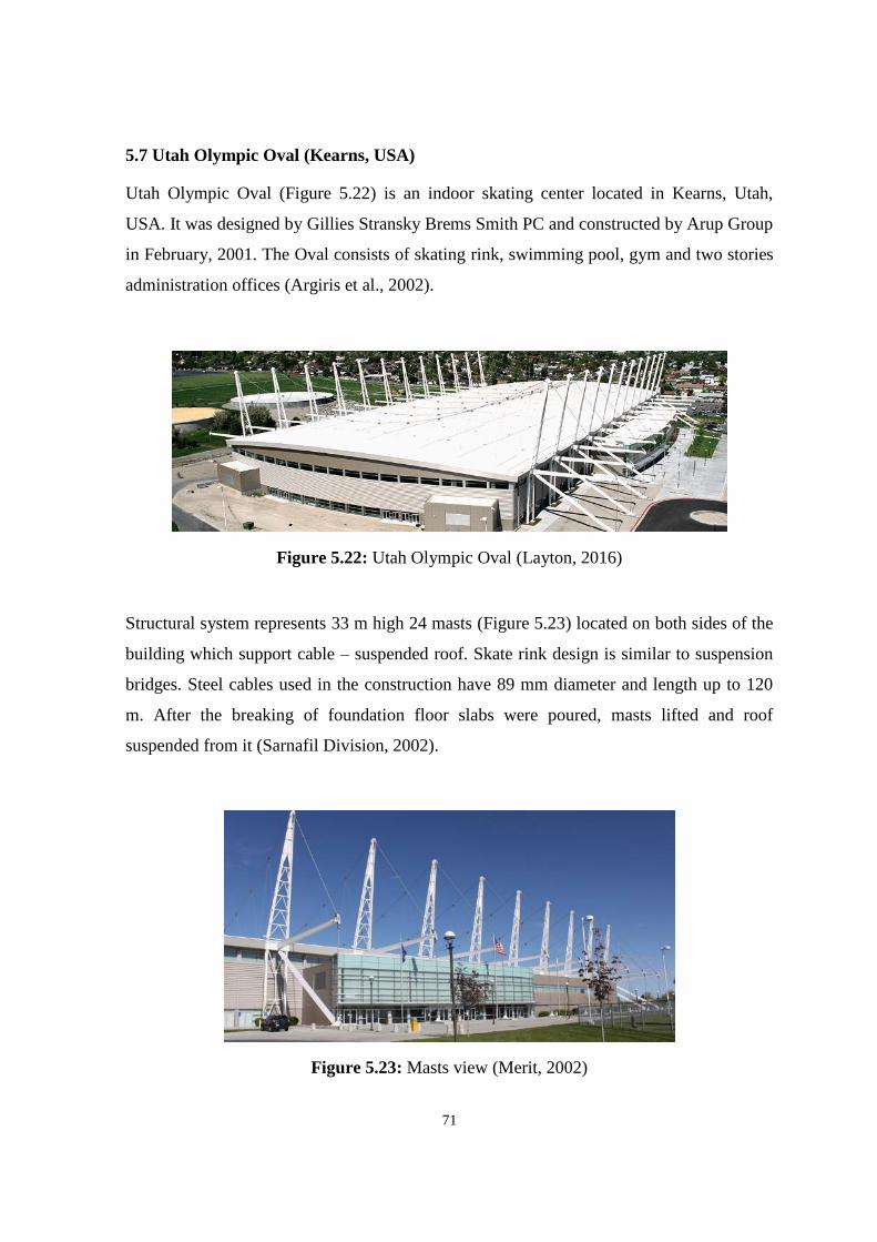
71
5.7 Utah Olympic Oval (Kearns, USA)
Utah Olympic Oval (Figure 5.22) is an indoor skating center located in Kearns, Utah,
USA. It was designed by Gillies Stransky Brems Smith PC and constructed by Arup Group
in February, 2001. The Oval consists of skating rink, swimming pool, gym and two stories
administration offices (Argiris et al., 2002).
Figure 5.22: Utah Olympic Oval (Layton, 2016)
Structural system represents 33 m high 24 masts (Figure 5.23) located on both sides of the
building which support cable – suspended roof. Skate rink design is similar to suspension
bridges. Steel cables used in the construction have 89 mm diameter and length up to 120
m. After the breaking of foundation floor slabs were poured, masts lifted and roof
suspended from it (Sarnafil Division, 2002).
Figure 5.23: Masts view (Merit, 2002)

72
Suspended cables which carry the arena roof were connected to the 95 m long trusses with
the dimensions of 92 cm (Figure 5.24). Minimized height of trusses helped to decrease
spent steel amount by 953 tons (Sarnafil Division, 2002). Engineers produced a steel plate
fixed to the I-beam with the metal deck on it. Plate had connections for the cables on the
top of the roof. Metal cowling was welded to the plate 45 cm above the deck and quality
roofing fixed a wood bridle around the metal plate. The last step in roof cladding was
wrapping of waterproof membrane around the bridle (Sarnafil Division, 2002). For the
economic use of materials and sustainable design Utah Olympic Oval was awarded the
thirteen Global Leadership in Energy and Environmental Design.
Figure 5.24: Building section and elevation (ARCHUtah, 2017)
The complete building has 25 500 m² with the ceiling height of 17 m. Length of the
structure is 400 m. Skating rink (Figure 5.25) can host approximately 6 000 guest for each
competition (Merit, 2002).
Figure 5.25: Inside view (ARCHUtah, 2017)

73
5.8 Abuja Velodrome (Abuja, Nigeria)
Abuja Velodrome (Figure 5.26) was opened in 2003 for All African Games. It is a large –
scale complex of about 16 500 m² designed by Ralph Schuermann. Velodrome consists of
cycling track with 250 m length, public and administrative areas and being used for the
meeting and concerts in free time (Stimpfle, 2007).
Figure 5.26: Abuja velodrome (CANOBBIO, 2017)
Cable structure of the building is supported by 16 orbicular columns and 8 masts. Roof of
the building is protected by glass and ETFE combination. During the All African Games
the membrane roof was demolished by windstorm and required a rebuilding work
(Stimpfle, 2007).
In the new design architects and engineers stick to the idea of no alteration and
displacement of cables and structural supports. For the appropriate choice of right cable net
type computer aided design was used and combination of pentagon / hexagon pattern was
selected (Figure 5.27). This pattern shaped a form as a previous roof but with additional
geometrical rigidity.

74
Figure 5.27: Cable roof structure (Corne, 2014)
Ridge cables were pre – tensioned at the middle point for the maintenance of pentagons
and hexagons (Figure 5.28). Force applied to the cable structure for gaining full stability
was determined by computer modelling.
Figure 5.28: Roof plan (Corne, 2014)
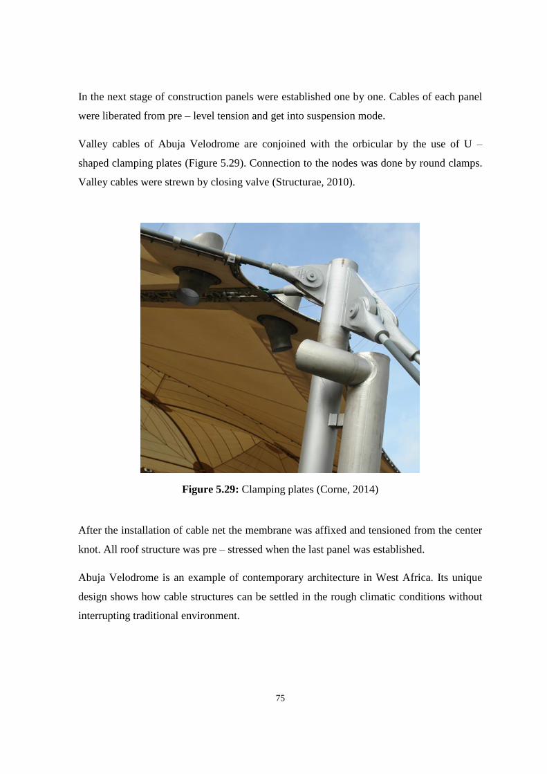
75
In the next stage of construction panels were established one by one. Cables of each panel
were liberated from pre – level tension and get into suspension mode.
Valley cables of Abuja Velodrome are conjoined with the orbicular by the use of U –
shaped clamping plates (Figure 5.29). Connection to the nodes was done by round clamps.
Valley cables were strewn by closing valve (Structurae, 2010).
Figure 5.29: Clamping plates (Corne, 2014)
After the installation of cable net the membrane was affixed and tensioned from the center
knot. All roof structure was pre – stressed when the last panel was established.
Abuja Velodrome is an example of contemporary architecture in West Africa. Its unique
design shows how cable structures can be settled in the rough climatic conditions without
interrupting traditional environment.

76
5.9 David L. Lawrence Convention Center (Pittsburgh, USA)
David L. Lawrence Convention Center (Figure 5.30) was built after several renovation and
expansion works in 2003. It is one of the greatest column – free spaces in the United States
of America. Project was designed by the Rafael Vinoly Architects as a green building and
in 2003 took a title of Platinum Leadership in Energy and Environmental Design for
natural cooling system (O'Callaghan, 2003).
Figure 5.30: View of the David L. Lawrence Convention Center (P - TEC, 2016)
Idea of the design for the David L. Lawrence Convention Center was taken from the
suspension bridges of Pittsburg. These three bridges are the only example of alongside
suspension bridgework lengthwise the same water stream in the world (Figure 5.31). Being
inspired by the bridges construction Rafael Vinoly chose cables construction as a symbol
of modern technological progress.

77
Figure 5.31: Aerial view of the convention center and Pittsburgh bridges (Green Roofs,
2017)
The recent structure covers 1.5 million ft² and encloses an exhibition hall, lecture halls,
meeting rooms, ballroom and a garage and represents two – story building constructed
from two main elements: steel frames and the structural cables. Steel frames pass all along
the line of south – north axis of the building. These frames are called bow and stern trusses
looking similar to the details of the vessel. Steel framing in the Convention Center carries
the loads of the floors and acts as an anchorage for the roof cables from one side. Cables of
the opposite side are fixed straight to the ground (Figure 5.32). Space trusses are placed
between the bow and stern steel frames to form the last floor. Cables span at the high to
support the roofing material (O'Callaghan, 2003).
Figure 5.32: Structural cables view (Green Roofs, 2017)

78
Cable structural system allows to achieve a pure column free space of the last floor which
is hosting an exhibition hall. Cables usage is more economical and effective for such a big
area. Each cable is derelict from the weld of the anchorage on the bow frame above a
central mast to the weld at the peak of the stern. Span of the roof is diverse along the length
of the building and approximately 90 – 122 meters. Cable beam composes of a convex or
protuberant upper cable used to withstand the downward force and a concave or depressed
lower cable for protecting from upwards. Cables represent seven – stranded ropes of 7.6
cm in diameter. Their total load bearing capacity is up to 16 000 kN. Plate from stainless
steel covers the upper cables and create a roof cladding. All cables are combined by the use
of vertical ties (Nadine, 2002).
To provide a natural lightning for the exhibition halls (Figure 5.33) cable stayed glass
facade was chosen as a functional detail and aesthetic attraction. But the combination of
two different materials gave an additional problems for Dewhurt, Macfarlene and Partners
engineers. Roof inclination was above the acceptable range and without special stiffening
system could cause the glass collapse. Structural engineers created a cable stayed glass
facade by shedding cables at mullion position and pre – tensioning amid the roof structure
and steel frames. By this procedure the deviation of the live load was minimized to 15 cm
and cables took an additional ability to withstand lateral and dynamic forces. Cables
maintain the glass and shape free and clean facade (Nadine, 2002).
Figure 5.33: David L. Lawrence Convention Center exhibition hall (Turner Construction,
2017)

79
Time – history computer analysis was used to prevent the influence tensioning process on
the steel frame of the structure. Engineers used this tool to simulate phases of the cables
tensioning and check its impact on skeleton deviation. It became feasible install the
framework with the desired last form after the process of cables pre – tensioning with the
use of computer modelling.
David L. Lawrence Convention Center serves as a good example how leading engineering
compositions can be adopted and integrated to the architectural structures. Cables appear
as a graceful form and carry long span and high loads.

80
5.10 Gerald Ratner Athletics Center (Chicago, USA)
Gerald Ratner Athletics Center (Figure 5.34) is the sport complex for the University of
Chicago designed by Cesar Pelli. Building was constructed in autumn 2003 and has
approximately 14 000 m² area included swimming pool, fitness center, hall of fame,
classrooms and offices (Eckmann et al., 2004).
Figure 5.34: Gerald Ratner Athletics Center (University of Chicago, 2016)
Ratner Center represents a unique structure with asymmetrical form justified by site
restrictions and disjointed on multiple levels cable – stayed roof. Cables in so – called
splayed position transfer the loads in 3 different directions. Structure is supported by the 25
m high inclined mast steadied with 15 cables and girders. Steel girders forming S – shape
and stabilized by the cables. Cables support the roof on the elevation of 8 m and connected
to the mast (Figure 5.35) in three different points: at its highest peak, at 16 m and 8 m.
Each level includes 6 backstay and 9 forestay cables. Backstay cables transmit the loads to
the concrete foundation through steel columns and help to resist buckling. Each girder axe
includes smaller masts. All the masts are inclined to 10º for the structural support
efficiency and design reasons. They are 45 cm in diameter and a height of 10 stories
building. For the better load resistance secondary masts were filled with concrete. Masts
were designed as a collar pin and each can resist up to 7 500 kN (Eckmann et al., 2004).

81
Figure 5.35: Elements of the masts (Eckmann et al., 2004)
For the future reducing of sagging and minimization of vibration all cables were pre –
stressed. Required tension level was found during computer aided design modelling
process using Robot analyzing software (Figure 5.36). Final structure elected cables with
the diameters between 36 mm and 66 mm and full – locked configuration for the corrosion
prevention. Individual cables represent 2 – 3 layered Z – shape wires with a circular core
(Eckmann et al., 2004).
Figure 5.36: Building section (Eckmann et al., 2004)

82
Hydraulic jacking system was inserted for the erection of cable – stayed roof. When the
primary supports were lifted all cables were connected to masts and girders with pre –
stress. For the wind resistance vertical beams were used as a side columns and horizontal
trusses which transfer the loads to frames (Figure 5.37). Roof cladding is the thin 19 cm
concrete layer and steel panels (Eckmann et al., 2004).
Figure 5.37: Masts and cables view (University of Chicago, 2016)
Massive structure of Athletics Center has a traditional deep foundation with innovative
triple tube jet grouting. This engineering technology utilizes a composition of grout, air
and water introduced under a high pressure to create mixture columns.
The University of Chicago Gerald Ratner Athletics Center is one of the first asymmetrical
cable – stayed buildings. Structural system allowed to use column – free volume for sport
facilities and created sustainable structure with natural light.
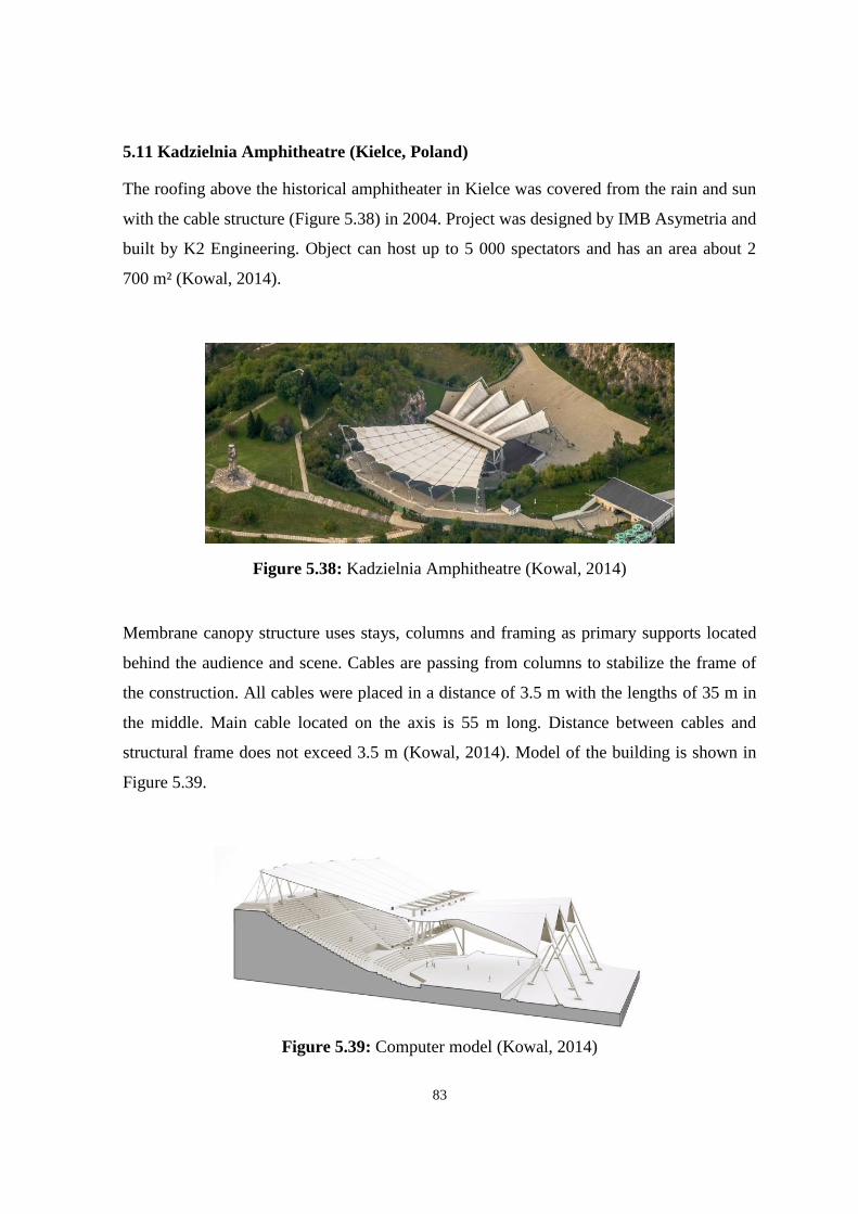
83
5.11 Kadzielnia Amphitheatre (Kielce, Poland)
The roofing above the historical amphitheater in Kielce was covered from the rain and sun
with the cable structure (Figure 5.38) in 2004. Project was designed by IMB Asymetria and
built by K2 Engineering. Object can host up to 5 000 spectators and has an area about 2
700 m² (Kowal, 2014).
Figure 5.38: Kadzielnia Amphitheatre (Kowal, 2014)
Membrane canopy structure uses stays, columns and framing as primary supports located
behind the audience and scene. Cables are passing from columns to stabilize the frame of
the construction. All cables were placed in a distance of 3.5 m with the lengths of 35 m in
the middle. Main cable located on the axis is 55 m long. Distance between cables and
structural frame does not exceed 3.5 m (Kowal, 2014). Model of the building is shown in
Figure 5.39.
Figure 5.39: Computer model (Kowal, 2014)

84
Wind tunnel modelling was used for the better design during cold and snowy times before
the beginning of canopy erection. Construction of the roofing began from the placement of
stays and columns. Frame was built contrary to the existing supports. Inclination of the
framing was done for the mounting of cables. Rods were pre – tensioned in 4 phases by
hydraulic jacks when all cables were fixed to the places and whole structure gained a pre –
stress level (Figure 5.40) (Tensi Net, 2012).
Figure 5.40: Cables and membrane fixing elements (Tensi Net, 2012)
Cable canopy tension process was done with the help of three machineries: windlasses,
hydraulic jacks system and anointment system. Winches were fixed to the rotary top of the
columns for the cables tensioning to open the membrane (Figure 5.41). Unfolded
membrane was locked till the last pose and all mechanical devices were launched. From
the inside roof reminds a folded membrane and it can be preserved during winter.
Figure 5.41: Membrane opening process (Tensi Net, 2012)

85
5.12 Moses Mabhida Stadium (Durban, South African Republic)
The Moses Mabhida Stadium is the stadium for multi – purposes built in Durban city of
South African Republic. Building is named after a former General Secretary of the SACP
Moses Mabhida and designed by Gerkan, Marg and Partners. Stadium was open in 2009
after 3 years of work. It can host 80 000 spectators (Silva and Survey, 2010).
Figure 5.42: Moses Mabhida Stadium (Pan Stadia, 2012)
The Moses Mabhida stadium (Figure 5.42) is a symbol of the nation integration with the
sport. The 106 meters tall central arch crossing the stadium incarnates this idea. The 360
meters long arch bears a web of total amount of 36 km long interlocking galvanized steel
cables. These cables form the tensile roof or structure. Arch has a height of 30 floors and
weights 2 600 t. It composes of 10 m long 56 sections. Massive arch serves as the world
first high – tech cable car (Figure 5.43) taking guests up to a viewing stage from where
panoramic view of the city is opening. Two south legs unite an adventure walk of 550
stairs to the top of the bow. This feature attracts international and local tourists. Till this
moment it entertained 15 events with total amount of visitors about 275 000 and over 100
congresses about 100 000 people. 35 000 people have visited stadium and approximately
3000 have climbed on the highest point of the arch (Koker, 2010).

86
Figure 5.43: Sky car and arch (PFEIFER, 2015)
The stadium arch allows concrete frame to prop the seating arena and works with the
foundation as the roof structure backing. The main structural system of the roof includes a
106 m high arch and 50 main ridge cables which constitute the 46 000 m² of roof area.
Ridge and valley cables are bind to the compression ring beard by steel columns (Figure
5.44) (Pan Stadia, 2012).
Figure 5.44: Sky car and arch (PFEIFER, 2015)
The roof cables are pre – fabricated to precise length needed for the geometry of the cable
net covering compression ring and arch. Any fluctuations from the dense geometrical
forbearance cause forces in the pre – stress cable net. This entails accurate statements
instructions of the forbearance out for support locations among the roof structure and

87
concrete. The rigidity of the concrete support structure is stringently measured and the
magnitude is specified by the structural analysis model.
The shear core gives the side steadiness for all sections of the stadium. The thickness of the
walls is 250 mm and 300 mm. The reason for this alteration of gauge is to gain consonant
deviations in the concrete structure at the meeting points with the roof at Level 6. Strains
transmitted from the steel columns to the concrete structure at Level 6 differ around the
periphery of the arch. The concrete structure affords side steadiness to the bowl at the
south and north parts, responses of the west and east parts represent axle strain as shown
on the section (Figure 5.45) (Nichols et al., 2010).
Figure 5.45: Section of the building (Haywood, 2014)
The foundation has the shape of extended rectangular boxes. Its walls are made of 800 mm
thick reinforced concrete. Two south foundation parts are 30 m by 4 m plan; north
foundation is 44 m by 7 m. The walls are poured with drilling mud / bentonite slurry or by
chests of 7 m by 20 m. Chests are fixed with 0.5 m into siltstone with a compressive
strength of 2 MPa.

88
All wall dashes include more than 4 vertical post – tensioned multi strand cables. The
vertical reinforcement is tied. The strands pass among the deep post – tensioned capping
beams. High post – tensioning cables are used to minimize the number of regular
reinforcing members and to strengthen the rigidity of the foundation.
Reinforced concrete springer plinth on vertex of the capping beams connects the bow and
foundation. Transition of the high loads to the foundation and geometrical forbearance
compelled the insertion of steel cast – in detail of the concrete plinth. The plinths have 10
m high by 16 m long trapezoid form. 420 m³ of concrete was used for the north plinths and
275 m³ for the south. All plinths are produced in a single pour. Only highest 1.2 m one
holds the coupled cast – in detail. Complementary measure is used to adjust the heat of
hydration to guarantee the excerpt of solid plinths. 100 mm thick polystyrene cladding
used as building insulation. Final form of the plinths is reached by the usage of pre – cast
20 t and 12 m high cladding panels lifted with the tilt – up technology (Koker, 2010).

89
5.13 Khan Shatyr Entertainment Center (Astana, Kazakhstan)
Khan Shatyr Entertainment Center (Figure 5.46) is the cultural and social typed structure
with the climatic shelter that proposes convenient microclimate all year in the Astana,
second coldest capital of the world, with the temperature -35º C in winter and +35º C in
summer. Building was opened in July, 2010 and has the traditional nomadic tent form.
Khan Shatyr means “the Tent of the Khan” or “largest tent”. Project of this large scale
cable structure was designed by Norman Foster.
150 m tall mast – stayed building has 200 m by 195 m elliptical base located at the north
end of the city's axis and it represents the highest point on the Astana skyline. Khan Shatyr
is considered as the world’s tallest tent structure. Total covered area is 100,000 m² and it
covers an urban – scale park with a 450 m running lane, shopping and spare – time
facilities such as restaurants, cinema and entertainment areas for exhibitions and events.
Landscape of the building is represented in green terraces, water park, wave swimming
pools and slides (Foster + Partners, 2010).
Figure 5.46: View of the Khan Shatyr Entertainment Center (Author, 2017)

90
To create large – scale columns free spaces with minimum supports engineers of Buro
Happold designed a one – mast stayed cable net conical shape. It was the best choice
according to the simplicity and potency of materials. With a compression mast to raise the
net and form volume beneath, the roof, as well approval for the building in the capital, in
tension can use cables to transfer the loads. It produces a strong iconic shape on the
skyline.
The cable net shown in Figure 5.47 is consisted of 16 circumferential and 192 radial
cables. Circumferential cable diameters are 76 mm to increase the maintenance. For the
system durability they are installed in couples and promote the fixation between peripheral
and radial cables. All cables are combined at the height 90 m on a ring at the vertex of
the steel tripod and cover to the inclined concrete base of the building. Four crossing bows
set the 120 m wide and 140 m long wide roof structure.
Figure 5.47: Cable system of the building (Birch, 2009)
The geometry of the net was chosen as the classic cone swayed to one side to bind to the
internal disposal and to give the Khan Shatyr its specific architectural form. Pre – stressed
against the hoop cables radial ones embrace the top ring of the compression mast to the
outer concrete base. 38 mm diameter 192 pairs of radial cables have different length from
125 m at the front to 70 m at the back (Figure 5.48). The hoop cables are
situated perpendicular to the ridge line. High pre – stress of 80 % of the peak forces is used
in the structure to operate deviations nearly 800 mm over the longest cable so the roof can
carry self – weight and snow / rain loads (Buro Happold Engineering, 2015).
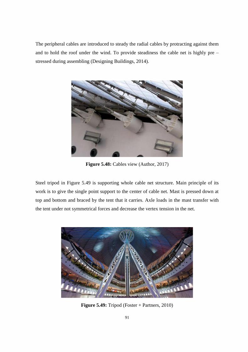
91
The peripheral cables are introduced to steady the radial cables by protracting against them
and to hold the roof under the wind. To provide steadiness the cable net is highly pre –
stressed during assembling (Designing Buildings, 2014).
Figure 5.48: Cables view (Author, 2017)
Steel tripod in Figure 5.49 is supporting whole cable net structure. Main principle of its
work is to give the single point support to the center of cable net. Mast is pressed down at
top and bottom and braced by the tent that it carries. Axle loads in the mast transfer with
the tent under not symmetrical forces and decrease the vertex tension in the net.
Figure 5.49: Tripod (Foster + Partners, 2010)

92
Tripod consists of two 70 m long widened front legs and 60 m high vertical back leg. Legs
are made from the triangular tubular steel trusses that organized from three chord trusses
with 1000 mm diameter round hollow sections. The back leg can withstand up to 140 MN
and front leg confronts to 50MN. Three – legged mast affords on –site assembly of the
stable ring in the air. Mast is fixed to the ground by the means of central 7 meters tall hub.
Hub is made of 150 mm thick plate maintaining 12 pin ended struts getting in touch with
the cable net top ring. Pin connections for the struts of 800 mm diameter give the joint of
the top ring (Figure 5.50). Center line of the hub conforms the sequent axial load from the
pre – stressed cable net. A 20 m diameter top ring made from a 1.6 m in diameter and 40
mm thick circular section. It is used to assemble all cables together (Birch, 2009).
Figure 5.50: Hub and pin connection (Author, 2017)
The tripod structure ensures steady constructible bottom and the joint top ring gives
displacement to reduce the loads in cable net. The movable part of the mast is done as
small element for easy temporary bracing during assembly. Cable net structures is able to
stir a bit to permit the cover material to change its form. On the top of the structure located
an architectural hat in the form of reversed cone made of insulated aluminum panels. It
allows the tent to be ventilated and lightened during the night.

93
Radial cables were elevated separately into a flaccid mode with cable clamps attached
fixed to receive the hoop cables located over the top of the radials. Tension is committed to
cables by a jacking detail at the base of the radial cables when all of them are fixed to form
the net and to let the adjustment of the cushions to go on. The ETFE or ethylene
tetrafluoroethylene cushions are put into extrusions from the ground and dragged to the
top. The foil cushions have three layers fixed together and have inflated middle layer.
Entertainment Center has high insulation by filling the ETFE cushions with air to contain
high thermal range. Dimensions of each cushion are 3.5 m width by 30 m length. The
length if it relies on the interval of the peripheral cables. They taper as the radial cables
approach to the cone. The ETFE cushion panels are fixed to the cables with the aluminum
clamping plates to endure the motion of the cables under climatic conditions. Flexible
ETFE conducts with the cable net’s diapason of stripping. The cables get closer and the
cushions change their form from an eye to a cylinder when the structure deviates. This
motion bow the use of continuous edge extrusions paralleled to the hoop cables which may
produce shift collars. Shifting peripheral joints permit the structure to stir like harmonica
(Birch, 2009).

94
5.14 Kauffman Center for the Performing Arts (Kansas City, USA)
Kauffman Center for the Performing Arts is a cultural center opened in September, 2011. It
took 5 years for famous architect Moshe Safdie and Arup Group to construct it. Kauffman
Center has 3 performance areas – 1800 seats Proscenium Theater, 1600 seats Concert Hall
and 400 visitors Celebration Hall. Building accommodates 4 – level parking for 1024 cars.
Total area of the building located on the slope of Kansas City is 33073 m² (Price, 2014).
Figure 5.51: Kauffman Center for Performing Arts (Safdie, 2011)
Structure is built onward the Kansas ridgeline. It is positioned with the front towards the
south and consists of two symmetrical semi shells and homo concentric arches (Figure
5.51). Performance Halls occupy both shells and have common backstage area.
This building represents one of the greatest large scale structures of contemporary
architecture. And its peculiar detail is the glass covered cable structure – The
Brandmeyer Great Hall assumed to maintain two performance areas. Moshe Safdie
declares the lobby as an expensive glazed porch contained by glass tent – like structure
(Gehringer, 2010). Transparent facade of The Brandmeyer Grand Hall gives a panoramic
view of the Kansas City for Cultural Center visitors and displays the impressive
appearance of spectators on the white background of interior from outside.
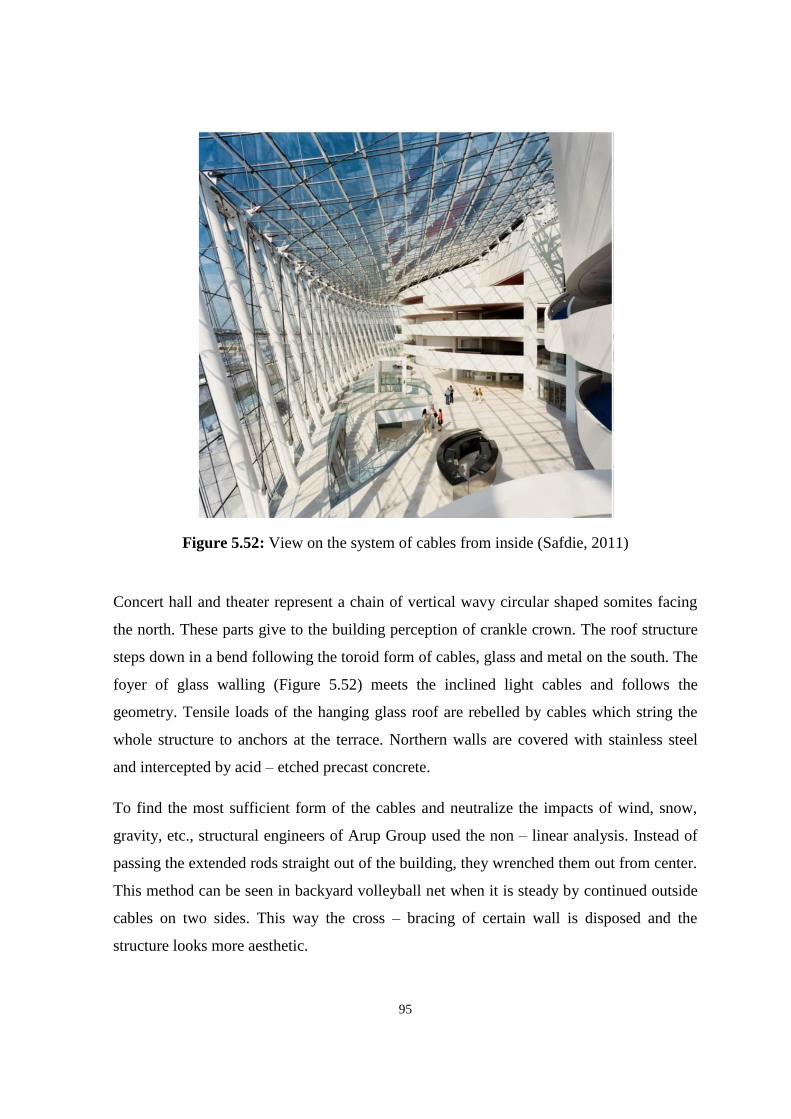
95
Figure 5.52: View on the system of cables from inside (Safdie, 2011)
Concert hall and theater represent a chain of vertical wavy circular shaped somites facing
the north. These parts give to the building perception of crankle crown. The roof structure
steps down in a bend following the toroid form of cables, glass and metal on the south. The
foyer of glass walling (Figure 5.52) meets the inclined light cables and follows the
geometry. Tensile loads of the hanging glass roof are rebelled by cables which string the
whole structure to anchors at the terrace. Northern walls are covered with stainless steel
and intercepted by acid – etched precast concrete.
To find the most sufficient form of the cables and neutralize the impacts of wind, snow,
gravity, etc., structural engineers of Arup Group used the non – linear analysis. Instead of
passing the extended rods straight out of the building, they wrenched them out from center.
This method can be seen in backyard volleyball net when it is steady by continued outside
cables on two sides. This way the cross – bracing of certain wall is disposed and the
structure looks more aesthetic.

96
Figure 5.53: Main entrance view and anchoring system (Bayly, 2012)
The 27 steel cables of the south facade are fixed in inserts or anchorages that have the
weight approximately 1.5 t (Figure 5.53). Embeds are the amplification of the foundation
under the building (Figure 5.54). The whole system was moved 2 – 6 inch to the south
during the process of straining of steel cables and this pre – tension process ensures the
additional stability and stand by the glass hall (Price, 2014).
Figure 5.54: View of the anchors (Safdie, 2011)

97
Structural roof cables stretching down to the lobby and terrace outside needed fire
protection. Fire engineers gained this aim by mutually creating digital model of usage of
high – strength kernels instead of cables on the exterior for the disposal of refractory. As
the result, smooth structural system with the striking boomerang plates connecting the
cables support the delicacy.
Table 1: Kauffman Center list of materials (Author, 2017)
The stainless steel performing areas structure is fluently converting to the glass hall. Glass
enlargement reveals the foyer to the skyline view. At night the glazing vanishes and shows
the flamingly lightened facades of the theater. This facade is made of slug plaster having a
shape of proceeded curvature pilled up balconies. Cables mould the sculptural forms
appeared under the glass (Kauffman, 2016). Table 1 above shows the list and amount of
materials used during the construction of Kauffman Center for the Performing Arts.
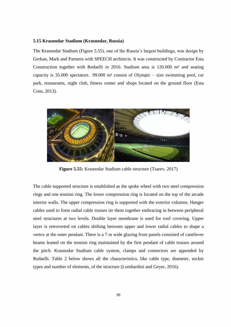
98
5.15 Krasnodar Stadium (Krasnodar, Russia)
The Krasnodar Stadium (Figure 5.55), one of the Russia’s largest buildings, was design by
Gerkan, Mark and Partners with SPEECH architects. It was constructed by Contractor Esta
Construction together with Redaelli in 2016. Stadium area is 120.000 m² and seating
capacity is 35.000 spectators. 99.000 m² consist of Olympic – size swimming pool, car
park, restaurants, night club, fitness center and shops located on the ground floor (Esta
Cons, 2013).
Figure 5.55: Krasnodar Stadium cable structure (Tsarev, 2017)
The cable supported structure is established as the spoke wheel with two steel compression
rings and one tension ring. The lower compression ring is located on the top of the arcade
interior walls. The upper compression ring is supported with the exterior columns. Hanger
cables used to form radial cable trusses tie them together embracing in between peripheral
steel structures at two levels. Double layer membrane is used for roof covering. Upper
layer is retroverted on cables shifting between upper and lower radial cables to shape a
vertex at the outer pendant. There is a 7 m wide glazing from panels consisted of cantilever
beams leaned on the tension ring maintained by the first pendant of cable trusses around
the pitch. Krasnodar Stadium cable system, clamps and connectors are appended by
Redaelli. Table 2 below shows all the characteristics, like cable type, diameter, socket
types and number of elements, of the structure (Lombardini and Geyer, 2016).
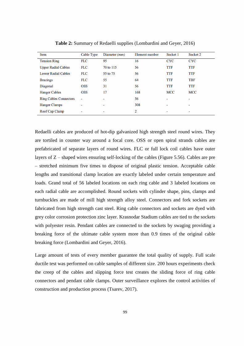
99
Table 2: Summary of Redaelli supplies (Lombardini and Geyer, 2016)
Redaelli cables are produced of hot-dip galvanized high strength steel round wires. They
are tortiled in counter way around a focal core. OSS or open spiral strands cables are
prefabricated of separate layers of round wires. FLC or full lock coil cables have outer
layers of Z – shaped wires ensuring self-locking of the cables (Figure 5.56). Cables are pre
– stretched minimum five times to dispose of original plastic tension. Acceptable cable
lengths and transitional clamp location are exactly labeled under certain temperature and
loads. Grand total of 56 labeled locations on each ring cable and 3 labeled locations on
each radial cable are accomplished. Round sockets with cylinder shape, pins, clamps and
turnbuckles are made of mill high strength alloy steel. Connectors and fork sockets are
fabricated from high strength cast steel. Ring cable connectors and sockets are dyed with
grey color corrosion protection zinc layer. Krasnodar Stadium cables are tied to the sockets
with polyester resin. Pendant cables are connected to the sockets by swaging providing a
breaking force of the ultimate cable system more than 0.9 times of the original cable
breaking force (Lombardini and Geyer, 2016).
Large amount of tests of every member guarantee the total quality of supply. Full scale
ductile test was performed on cable samples of different size. 200 hours experiments check
the creep of the cables and slipping force test creates the sliding force of ring cable
connectors and pendant cable clamps. Outer surveillance explores the control activities of
construction and production process (Tsarev, 2017).
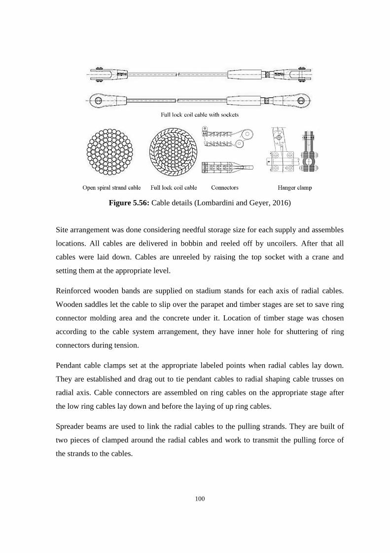
100
Figure 5.56: Cable details (Lombardini and Geyer, 2016)
Site arrangement was done considering needful storage size for each supply and assembles
locations. All cables are delivered in bobbin and reeled off by uncoilers. After that all
cables were laid down. Cables are unreeled by raising the top socket with a crane and
setting them at the appropriate level.
Reinforced wooden bands are supplied on stadium stands for each axis of radial cables.
Wooden saddles let the cable to slip over the parapet and timber stages are set to save ring
connector molding area and the concrete under it. Location of timber stage was chosen
according to the cable system arrangement, they have inner hole for shuttering of ring
connectors during tension.
Pendant cable clamps set at the appropriate labeled points when radial cables lay down.
They are established and drag out to tie pendant cables to radial shaping cable trusses on
radial axis. Cable connectors are assembled on ring cables on the appropriate stage after
the low ring cables lay down and before the laying of up ring cables.
Spreader beams are used to link the radial cables to the pulling strands. They are built of
two pieces of clamped around the radial cables and work to transmit the pulling force of
the strands to the cables.
101
To exclude the spreader beam from turning a stabilizing nose is inserted. Leveling of the
fork sockets properly contribute the intercalation of the pins in the last form. The spreader
beams are gathered on wooden stages at the highest part of the radial cables (Lombardini
and Geyer, 2016).
After the bracing cables are mounted separately begins the procedure of cables pre –
tensioning. Four cables are tensioned at the same time to retain the balance of the structure.
Krasnodar Stadium cable net composes of 112 radial cables, 56 diagonal cables and 16
tension ring cables. Radial cables are affixed to the tension ring connectors when the
tension ring is on the ground and arranged on axis. Radial cables are drag out by strands
and strand jacks are fit on the upper compression ring to assemble the whole cable net. The
tension ring is elevated by straining with two strand jacks every up radial cable
(Lombardini and Geyer, 2016).

102
5.16 Comments and Important Points
For the case studies we have selected 15 large scale structures in countries of different
climatic zones. All buildings were chosen to show variety of forms, functions and types of
cable system. Table 3 shown below summarizes case studies and demonstrates that cable
structural system can be easily combined with different materials and adopted in any type
of weather conditions for any types of the buildings.
Table 3: Summary of case studies (Author, 2017)

103
5.17 Proposals for the Near East University Campus (NEU lake and park)
Considering cable structures suitability with different types of topography we have chosen
Near East Campus and Near East Part for the proposals sites. Nicosia weather conditions
allow to build cable system which will meet regional requirements and symbolize
contemporary architecture without disrupting of existing buildings and hardscape. As the
cladding variety of materials may be used. Table 4 shows possible options for
Mediterranean subtropical semi – arid climate and displays its main characteristics.
Table 4: Cladding materials (Material Properties Database, 2009)
It is important to notice that cladding materials does not bear the load and does not act as a
structural element. But the material choice may influence building efficiency and
maintenance so designers should pay attention to its physicochemical properties.
We have designed two different in scale projects which use structural cables as the main
system. Detailed description of proposals for the Near East Campus design has been
presented below.

104
5.17.1 Cable structure canopy
Considering Cyprus climate with its hot summer and high solar energy Near East Campus
needs sun shaded places for rest and social activities. We have proposed cable structure
canopy (Figure 5.57) with the arch type primary support. Lake and its surrounding has
been chosen as the site.
Figure 5.57: Cable structure canopy proposal (Author, 2017)
Arch shown in Figure 5.58 was chosen for the primary support for its ability to carry the
loads and aesthetical view. For both structural and not structural elements we preferred
white color as a resemblance to existing buildings located nearby.
Figure 5.58: Arch type primary support for the canopy (Author, 2017)

105
For the materials of canopy PVC or textile membranes could be used. It may provide a
shade in a hot time or protect from the rains and wind in cold. Tribunes and seats can be
placed under canopy for the comfortability of people (Figure 5.59).
Figure 5.59: Membrane and tribunes beneath it (Author, 2017)
We believe that cable structure canopy (Figure 5.60) can serve as a good shelter element.
Arch can be used not only for support of the structure but also as a landmark for the lake in
Near East Campus.
Figure 5.60: Night view (Author, 2017)

106
Primary structural support can be made in different variations. Limitations of the design is
architects and engineers imagination. In the Figure 5.61 below have shown possible kinds
to be used in this project. Need to be mentioned that arch configuration and its load bearing
capacity should be properly calculated with special computer aided design programs.
Figure 5.61: Possible design variations of primary structural support (Author, 2017)

107
5.17.2 Near East Park
For the main project as the proposal design we have selected Near East Park located on the
main road to the Near East University. It represents wide open area with the free land
which is used for events and holiday celebrations. Near East Park can become one of the
Cyprus attractions with the variety of semi – open and covered buildings. Our design
proposal consists of cable – stayed canopies, gazebos, enclosed cable structures for
conference hall or museum, semi – open amphitheater, entrance canopy and suspended
bridge across small artificial pond (Figure 5.62).
Figure 5.62: Near East Park site view (Author, 2017)
Cables of this project play severe functions in suspended and stayed structures. Main of
them are:
Transferring of the loads and strengthening of the cladding;
Acting as the tensile support members along the edges (valley and ridge cables);
Steadying all stiff elements;
Ensuring the paths for the force flows;
Providing the entirety of the whole structure.

108
Entrance structure shown in Figure 5.63 plays a role of the landmark and shading space. It
is conceived to be built of steel cables with arch – type structural supports.
Figure 5.63: Entrance structure and view under it (Author, 2017)
Considering Cyprus climate and live loads, as the net type it is preferable to use two – way
cable net configuration (Figure 5.64). This type, put into tension, enlarges the inside
stresses of the cables intersection nodes which lead to the more rigid and steady net
system.
Figure 5.64: Cable - net canopy and scene (Author, 2017)
Idea of the Near East Park canopies is taken from the tents with pillars supported by the
cables which transfer the loads by structural elements to the ground.

109
Circular arrangement of the structural cables in fully enclosed buildings (Figure 5.65)
allows to collect them to the ring beam instead of extending to the ground. This method
produces low circuit of the forced and found to be very economical in the usage of
materials.
Figure 5.65: Near East Park enclosed building and their plans (Author, 2017)
Amphitheater shown in Figure 5.66 is designed for the open air events or ceremonies
during the warm days. Orbicular plan is found to be suitable with the function of the
structure. Materials represent combination of steel, wood and membrane.
Figure 5.66: Amphitheater view (Author, 2017)
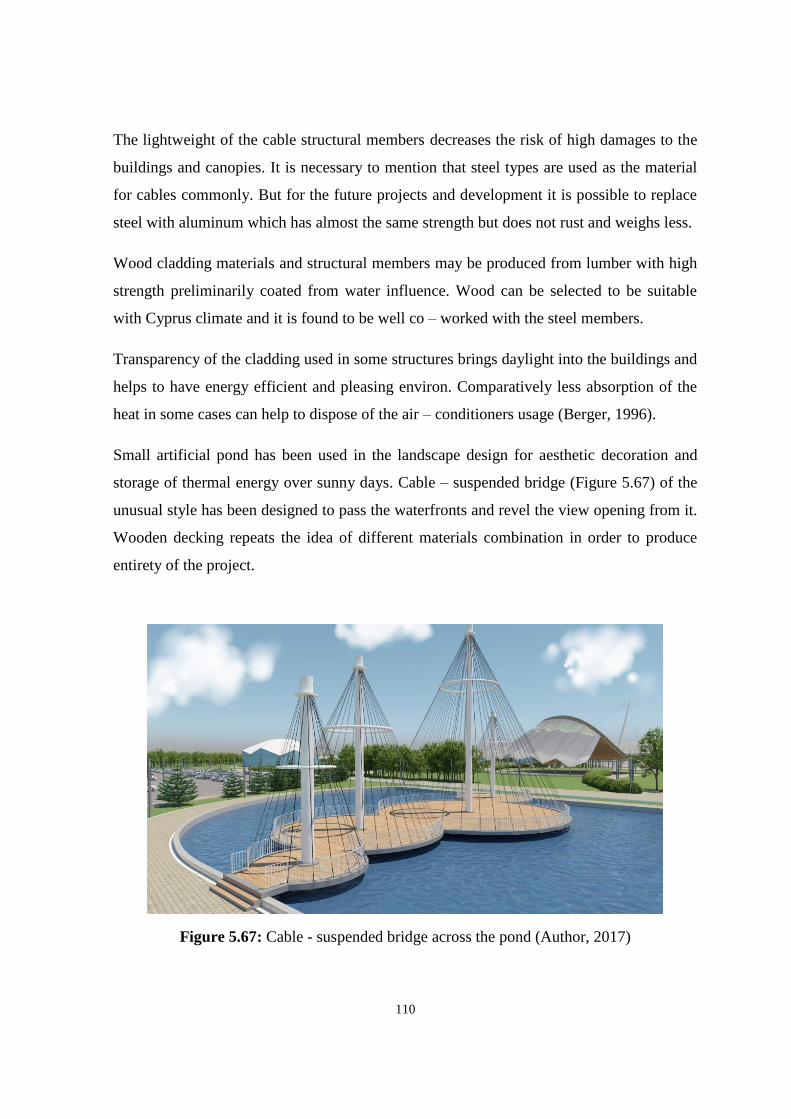
110
The lightweight of the cable structural members decreases the risk of high damages to the
buildings and canopies. It is necessary to mention that steel types are used as the material
for cables commonly. But for the future projects and development it is possible to replace
steel with aluminum which has almost the same strength but does not rust and weighs less.
Wood cladding materials and structural members may be produced from lumber with high
strength preliminarily coated from water influence. Wood can be selected to be suitable
with Cyprus climate and it is found to be well co – worked with the steel members.
Transparency of the cladding used in some structures brings daylight into the buildings and
helps to have energy efficient and pleasing environ. Comparatively less absorption of the
heat in some cases can help to dispose of the air – conditioners usage (Berger, 1996).
Small artificial pond has been used in the landscape design for aesthetic decoration and
storage of thermal energy over sunny days. Cable – suspended bridge (Figure 5.67) of the
unusual style has been designed to pass the waterfronts and revel the view opening from it.
Wooden decking repeats the idea of different materials combination in order to produce
entirety of the project.
Figure 5.67: Cable - suspended bridge across the pond (Author, 2017)
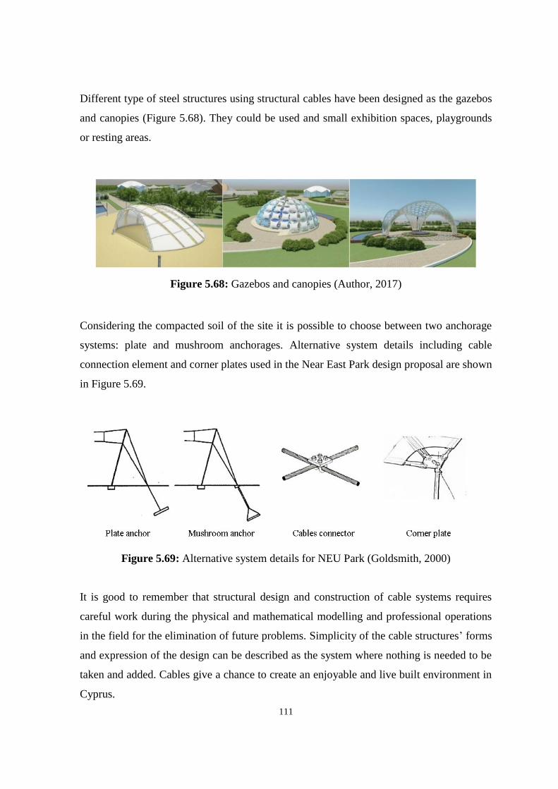
111
Different type of steel structures using structural cables have been designed as the gazebos
and canopies (Figure 5.68). They could be used and small exhibition spaces, playgrounds
or resting areas.
Figure 5.68: Gazebos and canopies (Author, 2017)
Considering the compacted soil of the site it is possible to choose between two anchorage
systems: plate and mushroom anchorages. Alternative system details including cable
connection element and corner plates used in the Near East Park design proposal are shown
in Figure 5.69.
Figure 5.69: Alternative system details for NEU Park (Goldsmith, 2000)
It is good to remember that structural design and construction of cable systems requires
careful work during the physical and mathematical modelling and professional operations
in the field for the elimination of future problems. Simplicity of the cable structures’ forms
and expression of the design can be described as the system where nothing is needed to be
taken and added. Cables give a chance to create an enjoyable and live built environment in
Cyprus.
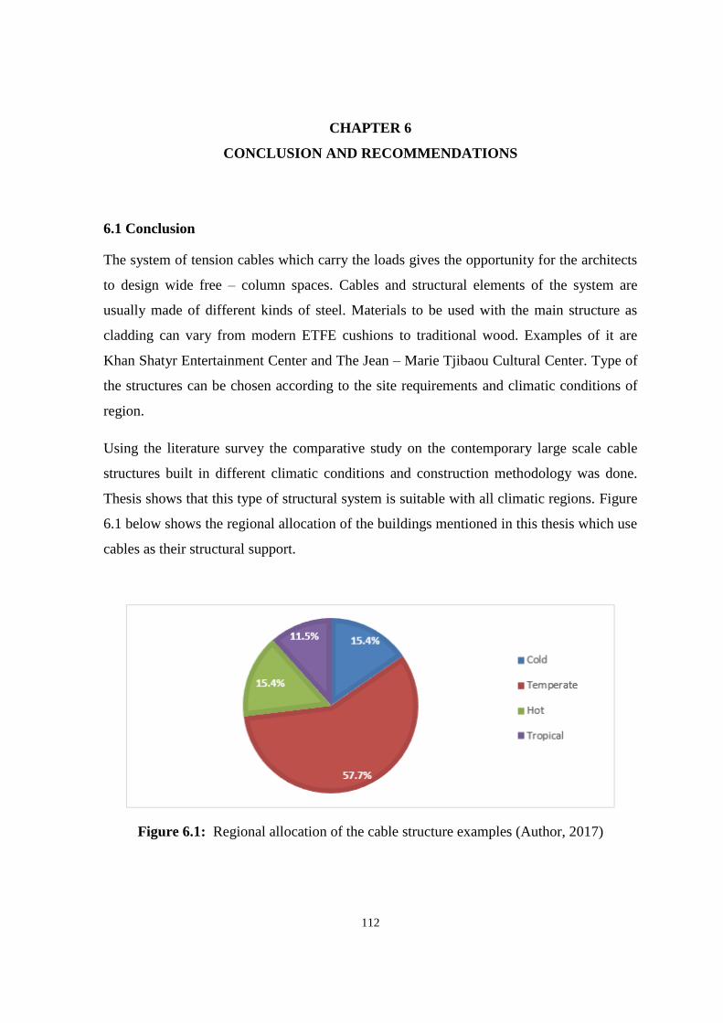
112
CHAPTER 6
CONCLUSION AND RECOMMENDATIONS
6.1 Conclusion
The system of tension cables which carry the loads gives the opportunity for the architects
to design wide free – column spaces. Cables and structural elements of the system are
usually made of different kinds of steel. Materials to be used with the main structure as
cladding can vary from modern ETFE cushions to traditional wood. Examples of it are
Khan Shatyr Entertainment Center and The Jean – Marie Tjibaou Cultural Center. Type of
the structures can be chosen according to the site requirements and climatic conditions of
region.
Using the literature survey the comparative study on the contemporary large scale cable
structures built in different climatic conditions and construction methodology was done.
Thesis shows that this type of structural system is suitable with all climatic regions. Figure
6.1 below shows the regional allocation of the buildings mentioned in this thesis which use
cables as their structural support.
Figure 6.1: Regional allocation of the cable structure examples (Author, 2017)

113
All the cable structures are incurred to the impact of climatic conditions. They can
negatively influence the health of cables and shorten the lifetime of the building. This
thesis indicates the most important of climatic problems to which architects and engineers
should pay attention. Table 5 gives a summary review of possible solutions in the case of
the nature impact on cable structural system.
Table 5: Climatic problems and their solutions (Author, 2017)
The intensive search of information about large scale cable structures in different climatic
zones though a literature survey and on – site observation of Khan Shatyr Entertainment
Center, Astana helped to create a comparative table to evaluate the changes appeared in
cable systems in different historical periods. From the historical background review we can
summarize that, together with appearance of new materials and construction technologies,
scale of cable structures is progressively growing. Till the 2016 height of the buildings
could rise up to approximately 150 meters from the nearly 20 m tall first example of
temporary exhibition structure. Figure 6.2 is the scatter chart of cable structures
development during the past years. It shows the variations of the building heights in certain
year.

114
Figure 6.2: Scale development of cable structures (Author, 2017)
With the help of Table 6 (pp.116-117) we can emit some critical points in the
chronological development of cable structure:
Starting from 1970’s cable structures started to increase in its scale. Olympiapark in
Germany is the first example of large scale cable system. Its roof covers stadium,
tracks and pools of a big area;
Cable structures can be constructed in different climatic zones and adopted to
variable temperatures and natural influences. For example, Diplomatic Club was
built in Riyadh, Saudi Arabia with extremely hot climate, Vancouver Expo in
Vancouver, Canada with humid continental climate and Khan Shatyr Entertainment
Center was constructed in Astana, Kazakhstan where climate is cold continental;
If in the beginning of cables usage they served only as exhibition spaces, usually
temporary, nowadays we can say that functions of structures had widened to
stadiums, airports, research facilities, cultural and entertainment centers. It shows
that cable structures can be adoptable to different goals and their purpose has
changed from the temporary structures to a life – long permanent buildings;

115
Form of the buildings evolved from the simple tents into complex geometry such
as hyperbolic paraboloids. The most often used shapes are conic, elliptical
arrangement and circular stayed forms. Geometry of the complex structures
requires special computer modelling;
Elements of the structural system had been developed throughout the history.
Simple cables are replaced with the cable net, usually pre – stressed to resist larger
loads and new types of details took a place in cable structures. One of the newest
primary support types called tripod can be seen in Khan Shatyr example. It allows
structure to withstand northern winds and carry the building itself;
Primary structural support can vary in their form and materials. For example,
Rhoen Clinic in Bad Neustadt, Germany uses wooden masts to transfer the loads to
the ground, Dulles International Airport in Virginia, USA transmit the loads
through the reinforced concrete pillars;
Lightweight of the cables allows to span wide distances to produce more open
spaces;
Contemporary cable architecture can be done in the combination with traditional
materials like masonry and wood. It shows that cables are combinable with
different types of materials without severance effect;
Developing in the materials technology gave a chance for the structural cables to be
syndicated with new products such as ETFE, PTFE and silicate glass. Cables nature
and physics allow to use a combination of cladding types. For example, Abuja
Velodrome in Abuja, Nigeria uses as a roof material glass and ETFE;
Easy combination of cables with different covering materials for roof cladding
widens the possible ways in structural design;
Cable structural buildings can be made in accordance with the rules of sustainable
and environmental design. Example is David L. Lawrence Convention Center in
Puttsburgh, USA;
Cable structures are highly efficient and the wires can be produced 5-6 times higher
the strength of the normal structural steel.

116
Table 6: Comparative study on large scale cable structures (Author, 2017)
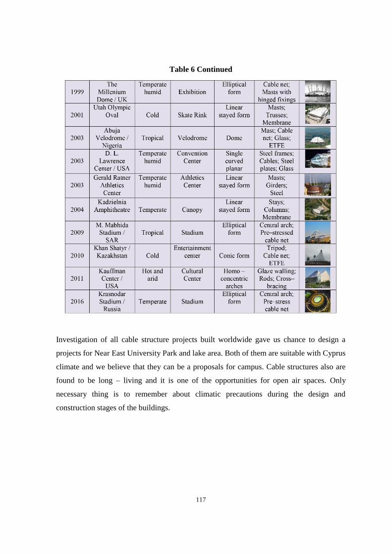
117
Table 6 Continued
Investigation of all cable structure projects built worldwide gave us chance to design a
projects for Near East University Park and lake area. Both of them are suitable with Cyprus
climate and we believe that they can be a proposals for campus. Cable structures also are
found to be long – living and it is one of the opportunities for open air spaces. Only
necessary thing is to remember about climatic precautions during the design and
construction stages of the buildings.

118
Table 7 below shows advantages and disadvantages of the cable structural system. We
hope that this table can serve as a guide for architects in the choice of appropriate system.
Table 7: Advantages and disadvanatges of cable systems (Author, 2017)

119
6.2 Recommendations
The following recommendations are offered for related research and practice in the field of
cable structures:
1. Considering the changing nature of technology, a series of longitudinal studies,
based on this model, would testify trends and thereby increase the potential
decisions regarding cable structures construction and monitoring would be
relatively current and less exposed to personal prejudice;
2. While the current spheres of construction consider the technologies from a global
viewpoint, it may be advantageous to conduct research based on the different
locations of the cable buildings and diverse directions of inquiry such as chemistry,
physics, materials innovations, nanotechnology, etc.;
3. Vibration health monitoring (VHM), which uses the innate periodicity and mode
forms as sensitive to damage features, can be used for the check of weakening of
the cables, sagging of the bars and the maintenance of structure. This method can
enhance the lifetime of the buildings;
4. Processes of the pre – tension and pre – stressing of the cables enlarge the stiffness
and durability of the cables and whole structure.
5. Possibly use the Integrated Project Delivery method in the all phases of cable
structures design and construction.
Recommendation for improving this study:
1. During inquiring the term “cable structures” precisely define or delimit the term;
2. Separate and add questions about essential fields of technical specifications or
technical requirements that are not aimed at achieving proficiency in other specific
areas;
3. Add the information about construction methodology and climatic problems
solutions using innovated sources.
120
REFERENCES
Aćić, M., Vlajić, L. M., and Kostić, D. (2013). Determination of prestressing levels for
cables trusses as function of their stability. Gradevinar, 21(5), 1097 – 1110.
Allen, E., and Zalewski, W. (1998). Shaping Structures. New York, NY: John Wiley &
Sons.
Ambrose, J., and Tripeny, P. (2016). Simplified Engineering for Architects and Builders.
12th edition. New York, NY: John Wiley & Sons.
ARCHUtah. (2017). Olympic Oval. Architecture in Utah. Retrieved January 20, 2017 from
http://www.archutah.com/built_project/olympic-oval/
Argiris, L., Barandiaran, I., Tonks, N., and Walker, S. (2002). The Utah Oval: Olympics
and legacy, Salt Lake City, USA. The Arup Journal, 12(2), 29-35.
Ashwear, N., and Eriksson, A. (2016). Vibration health monitoring for tensegrity
structures. Mechanical systems and signal processing, 5(2), 20-23.
Barden, W. R. (2006). A Fabric Roof For Denver’s New Airport Terminal. In proccedings
of the RCI 21st International Convention (pp. 58-60). New York, NY: RCI Press.
Bayly, M. J. (2012). Weekend in Kansas City, Missouri. Retrieved June 19, 2017 from
http://www.thewildreed.blogspot.com/2012/06/weekend-in-kansas-city.html
Behrends, W. (2015). Brand - Briesen airfield structure. The Great Airships of Count
Zeppelin (pp. 110-111). Morrisville, NC: Lulu.
Berger, H. (1996). Light Structures, Structures of Light. Boston, MA: Birkhauser.
Bing, W. B. (2004). Free – standing tension structures. From tensegrity systems to cable –
strut systems. Boston, MA: Spon Press.
Birch, A. (2009). Khan Shatyr Entertainment Center. Retrieved April 9, 2017 from
http://www.fosterandpartners.com/projects/khan-shatyr-entertainment-center/

121
Burgo, A. (2014). Nervi Projects. Mantua Plant. Retrieved March 15, 2017 from
http://www.burgo.com/en/paper/works-of-art/nervi
Buro Happold Engineering. (2015). A desert rose. Retrieved March 15, 2017 from
http://www.burohappold.com/projects/tuwaiq-palace/
Cai, C. S., Wu, W. J., and Araujo, M. (2007). Cable Vibration Control with a TMD – MR
Damper System: Experimental Exploration. Journal of Sound and Vibration, 9(6),
15-18.
Campagno, A. (1999). Intelligent Glass Facades. Boston, MA: Birkhauser.
CANOBBIO. (2017). Cable and membrane tensile structure for athletic fields with PVC
membrane for stadiums in Abuja, Nigeria. Retrieved March 17, 2016 from
http://www.archiexpo.com/prod/canobbio/product-55251-782240.html
Chan, K. (2016). Expo’86 Canada Pavilion: 21 Vintage Photos of Canada Place. Retrieved
March 20, 2017 from http://www.vancitybuzz.com/2016/05/vintage-photos-expo-
86-vancouver/
Columbia University. (2004). Dome Case Studies. Retrieved September 10, 2017 from
http://www.columbia.edu/cu/gsapp/BT/DOMES/SEOUL/seoul
Corne, E. (2014). Structure of Abuja Velodrome. Retrieved August 20, 2016 from
http://www.tensinet.com/database/viewProject/4372.html
Crawford, S. (2009). An Architecture of Relationships Built on the Use of Parametric
Modeling and Evaluative Analysis in Design. Morrisville, NC: Lulu.
Designing Buildings. (2014). Khan Shatyr Entertainment Centre. Retrieved March 7, 2017
from http://www.designingbuildings.co.uk/wiki/khan_shatyr_entertainment_center
Eckmann, D., Hautzinger, S., and Meyer, T. (2004). Design Considerations in Cable -
Stayed Roof Structures. Modern Steel Construction, 10(5), 12-13.

122
English, E. C. (2000). “Arkhitektura I Mnimosti”: The origins of Soviet avant – garde
rationalist architecture in the Russian mystical – pholisophical and mathematical
intellectual tradition. Boston, MA: Birkhauser.
Esta Cons. (2013). Krasnodar FK Stadyum. Retrieved March 10, 2017 from
http://www.estacons.com/eng/stad.html
Fentress Architects. (2016). Denver International Airport of Denver, Colorado . Retrieved
February 16, 2017 from https://www.architonic.com/en/project/fentress-architects-
denver-international-airport/5100647
Filler, M. (2015). Frei Otto’s Airborne Architecture. New York, NY: City Press.
Foster + Partners. (2010). Grand opening of the Khan Shatyr Entertainment Center in
Kazakhstan: the world's tallest tensile structure. Retrieved March 10, 2017 from
http://www.fosterandpartners.com/news/archive/2010/07/grand-opening-of-khan-
shatyr-entertainment-center-kazakhstan-the-world-s-tallest-tensile-structure/
Gehringer, M. (2010). A Breathtaking Prelude. Modern Steel Construction, 16(3), 21-23.
Goldsmith, N. (2000). Material for the New millennium. Widespan roof structures.
London: T. Telford.
Gordon, M. (2013). Jean – Marie Tjibaou Cultural Center case study. Modern Steel
Construction, 16(7), 40-42.
Gossen, P. (2004). Design with cables. Structural practices. STRUCTURE, 8(1), 21-22.
Green Roofs. (2017). David L. Lawrence Convention Center (Pittsburgh Convention
Center) South Terrace Structural System. Retrieved June 11, 2017 from
http://www.greenroofs.com/projects/pview.php?id=1555
Grimm, F. (2000). StahlbauIm Detail. Berlin: WEKA Baufachverlarge Gmbh.
Haywood, M. (2014). Moses Mabhida Stadium from Conception to Icon. Retrieved May
11, 2017 from http://www.5starsdurban.co.za/throwback-thursday-durbans-west/

123
Henrysson, E. (2012). Conceptual Design and Analysis of Membrane Structures. New
York, NY: Chalmers University of Technology.
Iori, T. (2009). Pier Luigi Nervi. Milan: Motta Architettura.
Irwin, S. (1999). Jean Marie Tjibaou Cultural Centre. Noumea, New Caledonia. Renzo
Piano Building Workshop with Paul Vincent and Alban Bensa. Modern Steel
Construction, 5(5), 35-37.
Joye, S. (2010). Cable roofs. In proceeding of the 1st SoletancheBachy and Freyssinet
Meeting. Paris: Freyssinet.
Kauffman, J. I. (2016). Kauffman Center for the Performing Arts. Chicago, IL: Andrews
McMeel Publishing.
Kidder Smith, G.E. (2012). Source Book of American Architecture: 500 Notable Buildings
from the 10th Century to the Present. New York, NY: Princeton Architectural
Press.
Koch, K. M. (2004). Membrane Structures. Berlin: Prestel Verlag.
Koker, V. D. (2010). Project Awards: Winners and Finalists. Modern Steel Construction,
30(2), 18-21.
Kowal, A. (2014). Cable membrane structure of Kadzielnia Amphitheatre. Metal
Structures, 11(3), 12-14.
Lawson, M., and Bilyk, A. (2014). Steel constructions in Architecture. Kiev: Ukrainian
Center for Steel Construction.
Layton, C. (2016). Utah Olympic Oval Project. Retrieved March 10, 2017 from
http://www.laytonconstruction.com/UtahOlympicOval.html
Lazar, F., Neild, S. A., and Wagg, D. J. (2016). Vibration suppression of cable using tuned
inerter dumpers. Engineering Structures, 20(5), 11-14.
Lombardini, D., and Geyer, S. (2016). Cable erection of Krasnodar Stadium suspended
roof. Procedia Engineering, 12(5), 407 – 415.

124
Macdonald, A. J. (2001). Long – span structures. Second Edition. London: Architectural
Press.
Mainstone, R. J. (2001). Developments in structural form. Paris: Routledge.
Material Properties Database. (2009). Make It From. Retrieved January 11, 2017 from
http://www.makeitfrom.com/material-properties-database/
Merit, A. (2002). Utah Olympic Oval. Modern Steel Construction, 8(7), 13-15.
Mosila, A. (2014). The security systems of the Washington Dulles International Airport.
Retrieved May 12, 2017 from http://www.prezi.com/mi1ywlpkcmk7/the-security-
systems-of-the-washington-dulles-international-airport/
Nadine, M. (2002). Fatal Collapse in Pittsburgh. Engineering News Record, 30(3), 22-24.
Nerdinger, W., Meissner, I., Moller, E., and Grdanjski, M. (2005). Frei Otto, Complete
Works: lightweight construction, natural design. Boston, MA: Birkhauser.
Nichols, P., Ahmadi, N., Bagheri, Y., and Golestanirad, F. (2010). An Iconic Building and
a Successful Stadium. Moses Mabhida Stadium. Retrieved May 11, 2017 from
www.faculty.arch.tamu.edu/media/cms_page_media/4433/mosesmabhida.pdf
Nunninghoff, R. (2003). Long – term experience with Galfran. Surface, 15(11), 21-24.
O'Callaghan, J. (2003). An Anconventional Approach. Civil Engineering Magazine, 6(10),
33-35.
Oskoei, S. A. G., and McClure, G. (2008). Dynamic Analysis of Cable Roofs Under
Transient Wind: A Comparison Between Time Domain and Frequency Domain
Approaches. Tsinghua Science and Technology, 7(1), 53 – 57.
Page, T. (2016). Still on the drawing board: The greatest buildings that never were.
Boston, MA: Birkhauser.
Pan Stadia. (2012). Running Moses Mabhida Stadium. Retrieved June 15, 2017 from
http://www.panstadia.com/wp-content/uploads/2012/11/runningmosesmabhida.pdf

125
PFEIFER. (2015). Moses Mabhida Stadium - a demanding reference project by PFEIFER.
Retrieved June 11, 2017 from http://www.pfeifer.de/content/mosesmabhidastad/
index.html
Phocas, M. C. (2013). Lightweight Tensile Structures towards an Architectural and
Engineering Integration. Journal of Architectural Engineering Technology, 11(4),
40-44.
Price, C. S. (2014). A Symphony of Architecture and Air. Ottawa: Oberon Press.
P - TEC. (2016). Pittsburgh Technology Expo and Conference. Retrieved July 1, 2017
from http://www.pittsburghtradeshow.com/index.html
Rastorfer, D. (1988). Structural Gymnastics for the Olympics. Architectural Record, 2(1),
30-31.
Roberts, J. (2015). King Fahd International Stadium, Riyadh by J. Roberts Architects.
Retrieved July 5, 2017 from http://www.jrarchitects.co.uk/projects_gallery.html
Safdie, M. (2011). Kauffman Center for the Performing Arts. Retrieved September 2, 2017
from http://www.msafdie.com/projects/kauffmancenterfortheperformingarts
Sarnafil Division. (2002). SarnaProof: Project profile. Retrieved September 5, 2017 from
http://www.sarnafilius.com/sarna_proof/profile.html
Scheuermann, R., and Boxer, K. (1996). Tensile Architecture in the Urban Context.
Boston, MA: American Press.
Schock, H. J. (1997). Soft Shells: Design and technology of Tensile Architecture. Basel:
Birkhauser.
Seidel, M. (2009). Tensile Surface Structures: A Practical Guide to Cable and Membrane
Construction. New York, NY: John Wiley & Sons.
Silva, C., and Survey, A. (2010). Surveying the Moses Mabhida Stadium. Basel:
Birkhauser.

126
Stimpfle, B. (2007). Neuplanung des Velodroms in Abuja, Nigeria. Bauingenieur, 12(10),
12-15.
Structurae. (2010). Abuja Velodrome on the Largest Database. Retrieved March 5, 2017
from http://www.structurae.net/structures/abuja-velodrome
Tensi Net. (2012). Kadzielnia Amphitheatre Structure. Retrieved September 11, 2017 from
http://www.tensinet.com/database/viewProject/4538.html
Thompson, J. (2000). Globalizing Architecture. Flows and Disruptions. Boston, MA:
Birkhauser.
Travas, V., and Kozar, I. (2008). Static and dynamic analysis of a spatial catenary.
Gradevinar, 16(1), 62-64.
Tsarev, I. (2017). Complex solutions in the safety of contemporary sport facilities.
Moscow: AST Press.
Tucker, T. (2013). Georgia Dome has a new look for Final Four. Architectural Record,
27(1), 20-22.
Turner Construction. (2017). David L. Lawrence Convention Center. Retrieved January
10, 2017 from http://www.turnerconstruction.com/experience/project/1125/david-l-
lawrence-convention-center
University of Chicago. (2016). Ratner Athletics Center. Retrieved March 28, 2017 from
http://www.athletics.uchicago.edu/facilities/photos/ratner
Vanderberg, M. (1998). Cable nets. Detail in building. Chichester: Packard Publishing.
Warmbronn, A. F. (2015). Institute for Lightweight Structures. Stuttgart: Lentz Verlag.
Washington Airports Authority. (2015). History of Washington Dulles International
Airport. New York, NY: Metropolitan.
Webster, A. C., and Vaicaitis, R. (2003). Application of Tuned Mass Dampers To Control
Vibrations of Composite Floor Systems. Engineering Journal, 6(2), 120-122.

127
Werner Sobek Ingenieure. (2004). Rhoen Clinic. Retrieved February 3, 2017 from
http://www.wernersobek.com/englishweb/frameset.html
Wright, B. N. (2010). Tension structure connection details. New York, NY: John Wiley &
Sons.
WTTW. (2012). Catenary Curves: Scientific Experimentation. Retrieved February 20,
2017 from http://www.interactive.wttw.com/tenbuildings/curriculum/science.html
Yan, H., Yuan, Y., and Yu, J. (2016). Fatigue reliability analysis of cable considering
corrosion. Procedia Engineering, 12(8), 127 – 135.
128