example 11 – design of a frame (draft)
TRANSCRIPT
Example 11 – Design of a frame (draft)Fulop L, 25.10.2019, Espoo
- Part 1 and Part 2 is basic;- Part 3 more advanced;
This document summarizes the remake of the design calculations for the frame in the Access Steelexample SX029a-EN-EU. The first part of the document presents a step-by-step replication of thecalculations in the original example. The second part explores member level verifications of Consteel. Thethird part uses the features of ConSteel to design the steel frame using the automated features of thesoftware.
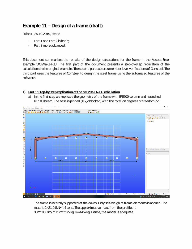
1) Part 1: Step-by step replication of the SX029a-EN-EU calculationa) In the first step we replicate the geometry of the frame with IPE600 column and haunched
IPE500 beam. The base is pinned (X,Y,Z blocked) with the rotation degrees of freedom ZZ.
The frame is laterally supported at the eaves. Only self-weigh of frame elements is applied. Themass is 2*21.91kN~4.4 tons. The approximative mass from the profiles is33m*90.7kg/m+12m*122kg/m=4457kg. Hence, the model is adequate.

b) We apply the different loads listed in SX029a-EN-EU. We introduce the load combinations frompage 3 of the example. We will concentrate on EN Combination 101 with permanent loads andsnow load, since it is the combination controlling the design of the column and rafter in theexample calculation.
We run the model with vertical loads in Combination 101 and check the internal forces againstthe table on Page 7 of SX029a-EN-EU. ConSteel gives 173.44kN vertical reaction force for eachsupport, 346.88kN total. This is to be compared with 344.7kN in the Access Steel example.Hence, loads are in line with the ones in the example.
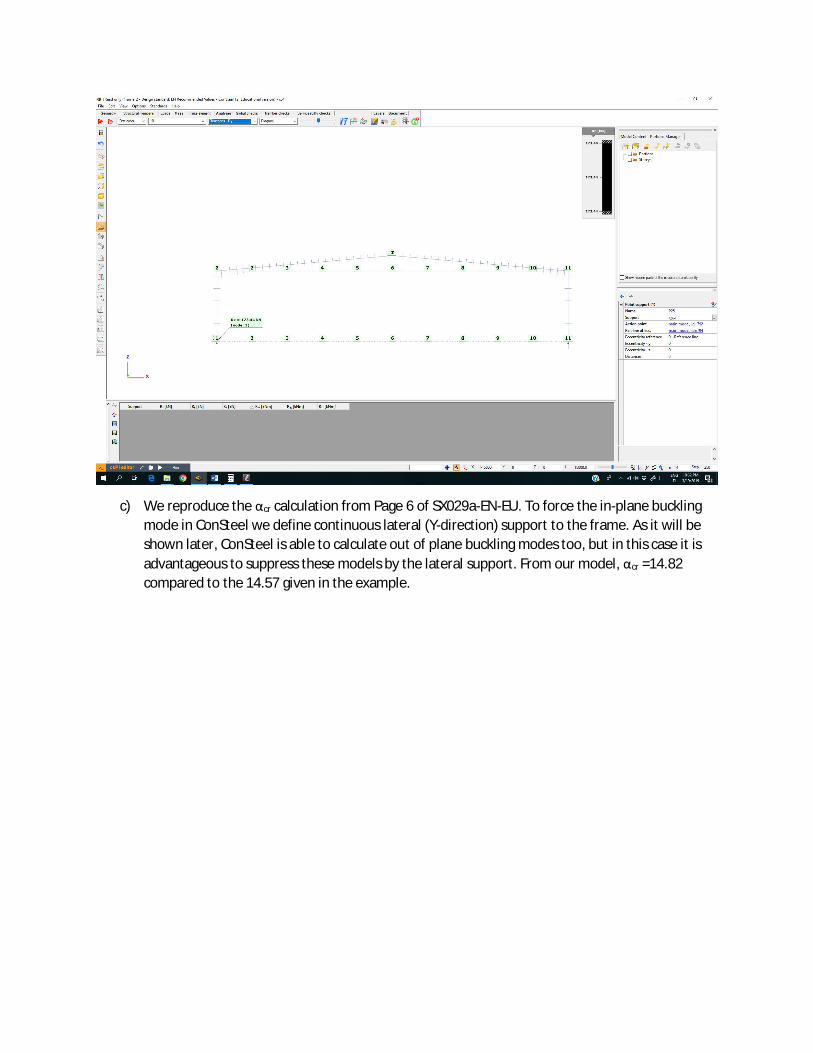
c) We reproduce the αcr calculation from Page 6 of SX029a-EN-EU. To force the in-plane bucklingmode in ConSteel we define continuous lateral (Y-direction) support to the frame. As it will beshown later, ConSteel is able to calculate out of plane buckling modes too, but in this case it isadvantageous to suppress these models by the lateral support. From our model, αcr =14.82compared to the 14.57 given in the example.

d) We introduce the equivalent horizontal force 0.552kN (Page 7 of SX029a-EN-EU) to simulate theeffect of imperfections. Combination 101 with this additional horizontal load is analyzed.Checking internal forces, the corner bending moment is 764.01kNm, compared to 754.98kNm inthe example. This ~1.1% difference can result from different discreditation of the frame intofinite elements. Especially the approximations used for the haunched part are not know.
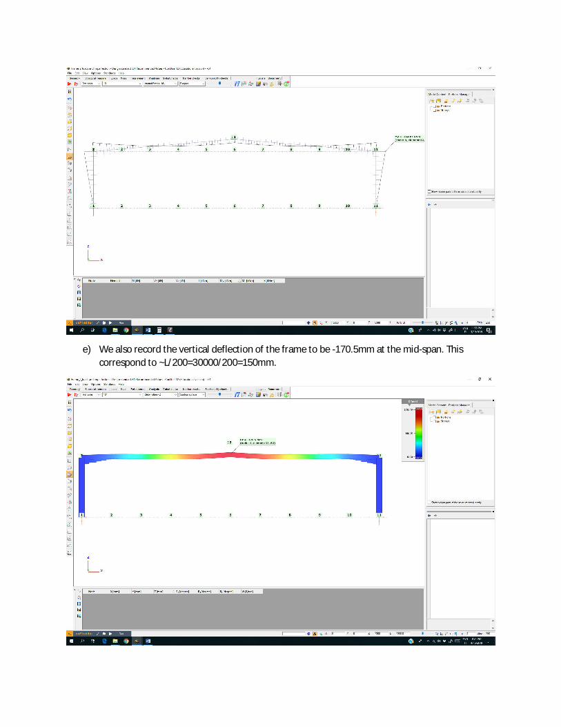
e) We also record the vertical deflection of the frame to be -170.5mm at the mid-span. Thiscorrespond to ~L/200=30000/200=150mm.

f) In addition, we can perform the buckling calculation from the Page 19 of SX029a-EN-EU. Weplace the recommended fictious support in the X direction to the left-hand side corner of theframe. We apply the largest vertical loads (Combination 101), while forcing the in-planebuckling. The obtained αcr =39.93 is comparable with the 37.37 from the example.
Hence, we conclude that we have a structural model compatible with the example calculation inSX029a-EN-EU. We can proceed to extract internal forces and preform the design checks as in theexample.
2) Part 2: Member checks of SX029a-EN-EU reproduced in ConSteela) Selecting the frame column from the previous static model, we reproduce the member checks
of SX029a-EN-EU. These are to be found in Chapter 6: Column verification starting on Page 9 ofSX029a-EN-EU.The critical forces are 53190kN(example) versus 53161 kN (ConSteel) for strong axis flexural,1956 kN (example) versus 1947.1 kN (ConSteel) and Mcr 1351 kNm (example) versus 1431.1kNm (Consteel).
The buckling reduction factors are 0.9813 (example) versus 0.983 (Consteel) for strong axisbuckling; 0.3495 (example) versus 0.36 (Consteel) for weak axis bucking and 0.8388 (example)versus 0.856 (Consteel) for the modified lateral-torsional buckling.
Consteel evaluates the factor for buckling verification and the utilization factors are 0.9534(example) versus 0.935 (Consteel).


3) Part 3: Remake of the frame calculation using the advanced features of ConSteel
In this part we will perform automated connections and buckling checks using advanced features ofConsteel.
First, we insert the frame corner elements (grey boxes in the picture). These elements will facilitatetaking corner stiffness into account, by eliminating the use of “Beam” within the length correspond tothe frame corner. The lateral support placed on the rafter may need to slightly relocated, since thefarter no longer extends to the corner region.
The effect on the frame can be checked, since the deflection is reduced to 164.8mm from the earlier170.5mm. Hence, the corner elements added stiffness:

We add adequate joints, using the “Create joints by model” wizard, or by creating the joints first and“Placing” them onto the frame model:

Three typologies of joints are required; for the base, corner and apex:

The base joint is basically pinned, but it blocks the ZZ direction rotation. This degree of freedom needsto be blocked in the model too by changing the degree of freedom settings for the bases. A few featuresof the base joints are shown below. Design forces for the joint are taken form the FEM model.Utilizations ratios are 22%, 44% and 20%, so the joint is adequate:

Features of the corner joint are also shown. Again, design loads for the joint are transferred from theFEM directly. It can be noted that, without stiffeners, the corner joint is inadequate strength withutilization 130%. It is also semi-rigid:

We add some stiffeners to increase the capacity of the joint. The lower stiffener, in order to strengthenthe compression side of the joint is indispensable to reach the design strength:

Other stiffeners may be added to increase stiffness and strength. For the calculation we will use theprevious configuration, with only a lower stiffener.
Finally, we configure the apex joint:
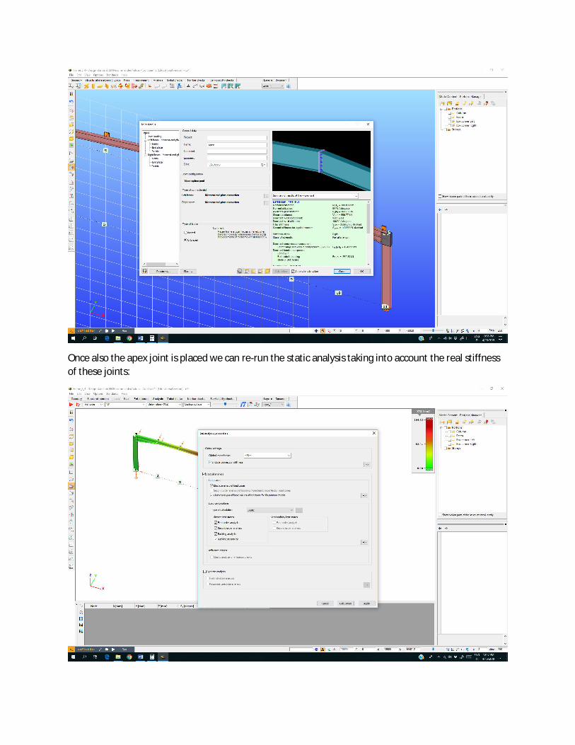
Once also the apex joint is placed we can re-run the static analysis taking into account the real stiffnessof these joints:

We can notice the changes in the frame response: deflection has increased to 228.9mm from theprevious 164.8mm! This demonstrates the important influence of the join stiffness:
Bending in the frame corner slightly reduced to 730.88kN. This also means that the apex bendingmoments has probably increased:
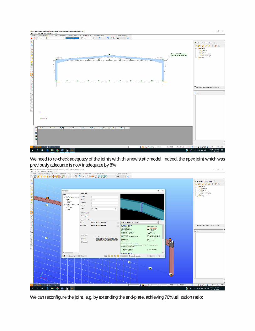
We need to re-check adequacy of the joints with this new static model. Indeed, the apex joint which waspreviously adequate is now inadequate by 8%:
We can reconfigure the joint, e.g. by extending the end-plate, achieving 76% utilization ratio:

All elements of the frame are adequate. The deflection has been reduced to 218mm, due to theincreased stiffness of the apex joint:

We can check the buckling modes and critical factors. For the dominant vertical load combination (101),considering in-plane and out of plane buckling modes, the critical multiplier is αcr=3.51, with a modeinvolving both column and beam in the haunch area:
Interesting to note that the buckling calculation is very sensitive to support conditions. If we allow ZZrotation of the frame bases, the critical factor drops to αcr=1.82, and column design checks would fail by5%. Hence, in this stage (and all stages) it is very important to adequately assess the effectiveness of thesupports! Design checks will be performed with the ZZ rotation blocked at the base.

We can perform the global check of all elements using the most conservative eigenvalues (criticalmultiplication factor):

All elements of the frame are now adequate with utilization ratios in the range of maximum 86%:
Hence, we can perform all frame calculation inside one software tool:
- We can take into account joint stiffnesses, and- iterate on the effect of joints stiffness on the frame design.- We can check the joints themselves.- Finally, an in-plane out of plane combined buckling analysis is possible using the EN1993-1
general method.