example-based model synthesis - gamma
TRANSCRIPT
Example-Based Model Synthesis
Paul Merrell∗
University of North Carolina at Chapel Hill
(a) (b)
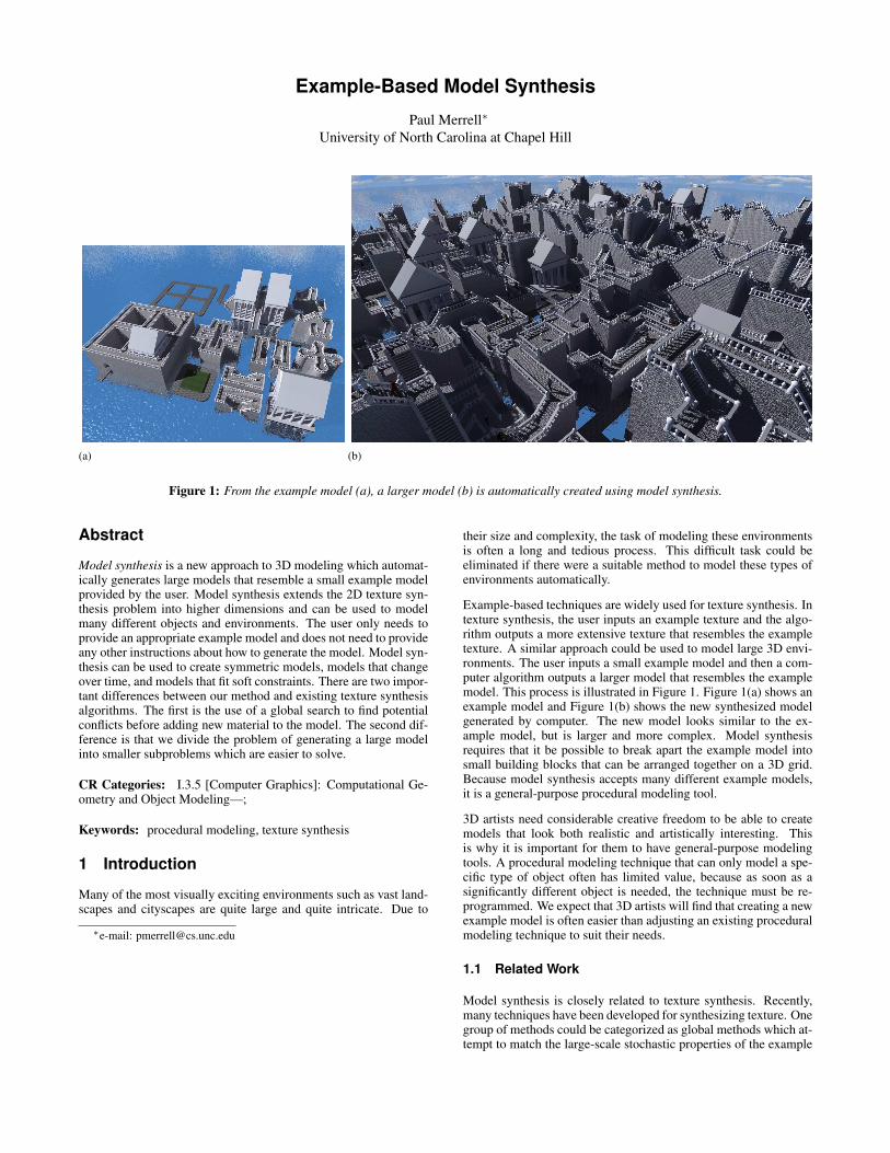
Figure 1: From the example model (a), a larger model (b) is automatically created using model synthesis.
Abstract
Model synthesis is a new approach to 3D modeling which automat-ically generates large models that resemble a small example modelprovided by the user. Model synthesis extends the 2D texture syn-thesis problem into higher dimensions and can be used to modelmany different objects and environments. The user only needs toprovide an appropriate example model and does not need to provideany other instructions about how to generate the model. Model syn-thesis can be used to create symmetric models, models that changeover time, and models that fit soft constraints. There are two impor-tant differences between our method and existing texture synthesisalgorithms. The first is the use of a global search to find potentialconflicts before adding new material to the model. The second dif-ference is that we divide the problem of generating a large modelinto smaller subproblems which are easier to solve.
CR Categories: I.3.5 [Computer Graphics]: Computational Ge-ometry and Object Modeling—;
Keywords: procedural modeling, texture synthesis
1 Introduction
Many of the most visually exciting environments such as vast land-scapes and cityscapes are quite large and quite intricate. Due to
∗e-mail: [email protected]
their size and complexity, the task of modeling these environmentsis often a long and tedious process. This difficult task could beeliminated if there were a suitable method to model these types ofenvironments automatically.
Example-based techniques are widely used for texture synthesis. Intexture synthesis, the user inputs an example texture and the algo-rithm outputs a more extensive texture that resembles the exampletexture. A similar approach could be used to model large 3D envi-ronments. The user inputs a small example model and then a com-puter algorithm outputs a larger model that resembles the examplemodel. This process is illustrated in Figure 1. Figure 1(a) shows anexample model and Figure 1(b) shows the new synthesized modelgenerated by computer. The new model looks similar to the ex-ample model, but is larger and more complex. Model synthesisrequires that it be possible to break apart the example model intosmall building blocks that can be arranged together on a 3D grid.Because model synthesis accepts many different example models,it is a general-purpose procedural modeling tool.
3D artists need considerable creative freedom to be able to createmodels that look both realistic and artistically interesting. Thisis why it is important for them to have general-purpose modelingtools. A procedural modeling technique that can only model a spe-cific type of object often has limited value, because as soon as asignificantly different object is needed, the technique must be re-programmed. We expect that 3D artists will find that creating a newexample model is often easier than adjusting an existing proceduralmodeling technique to suit their needs.
1.1 Related Work
Model synthesis is closely related to texture synthesis. Recently,many techniques have been developed for synthesizing texture. Onegroup of methods could be categorized as global methods which at-tempt to match the large-scale stochastic properties of the example
texture onto the new texture [Heeger and Bergen 1995; Portillaand Simoncelli 2000]. In a separate category are local region grow-ing methods which synthesize the texture pixel by pixel or patchby patch [Efros and Leung 1999; Wei and Levoy 2000; Efros andFreeman 2001]. Model synthesis more closely resembles the localmethods.
Model synthesis could be thought of as a generalization of texturesynthesis into three or more dimensions. Previous extensions oftexture synthesis used time as the third dimension [Doretto et al.2003; Wei and Levoy 2000; Kwatra et al. 2003]. Texture synthesishas also been used to create 3D geometric texture on the surface ofa given model [Bhat et al. 2004].
Wang tiles are small blocks of texture that can be arranged togetheron a grid to create larger textures and have been used in texturesynthesis [Cohen et al. 2003]. The 3D counterpart of a Wang tileis a Wang cube [II and Kari 1996]. Wang cubes have been usedto model asteroid fields [Sibley et al. 2004] and to render volumedata [Lu et al. 2004]. Synthesizing a model is not difficult aftera Wang cube set has been found. However, in order to form anacceptable Wang cube set many different parts of the model mustbe stitched together without creating seams where they meet. Thiscan be difficult to achieve on some models.
Context-based surface completion [Sharf et al. 2004] is designed tocomplete models where sections of the model are missing surfaceinformation. Surface completion fills in any missing sections withsurfaces that resemble the rest of the model. The rest of the modeleffectively acts as the example. Another tool [Funkhouser et al.2004] can be used to stitch together parts of many different examplemodels to create a new model. These two methods are useful formodeling individual objects, but model synthesis is better suited tomodeling large-scale structures.
Procedural modeling techniques that model specific objects orenvironments such as plants [Mech and Prusinkiewicz 1996;Prusinkiewicz et al. 2001], terrain [Musgrave et al. 1989], andbuildings [Muller et al. 2006; Legakis et al. 2001] have been ex-tensively studied [Ebert et al. 1998], but these methods require thatmany rules for generating the models be specified and are only ableto model a small class of objects. In contrast, model synthesis isa general-purpose procedural modeling tool. While the examplemodel must satisfy a few requirements, any example model thatdoes satisfy them can be used regardless of the type of object.
2 The Consistency Problem
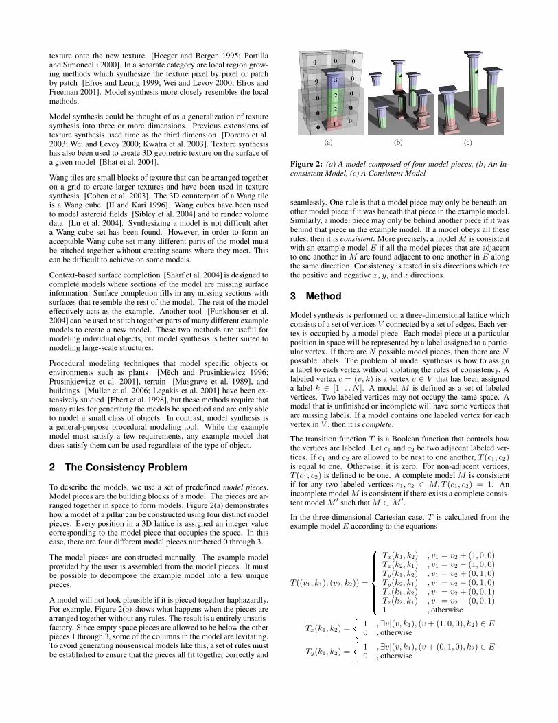
To describe the models, we use a set of predefined model pieces.Model pieces are the building blocks of a model. The pieces are ar-ranged together in space to form models. Figure 2(a) demonstrateshow a model of a pillar can be constructed using four distinct modelpieces. Every position in a 3D lattice is assigned an integer valuecorresponding to the model piece that occupies the space. In thiscase, there are four different model pieces numbered 0 through 3.
The model pieces are constructed manually. The example modelprovided by the user is assembled from the model pieces. It mustbe possible to decompose the example model into a few uniquepieces.
A model will not look plausible if it is pieced together haphazardly.For example, Figure 2(b) shows what happens when the pieces arearranged together without any rules. The result is a entirely unsatis-factory. Since empty space pieces are allowed to be below the otherpieces 1 through 3, some of the columns in the model are levitating.To avoid generating nonsensical models like this, a set of rules mustbe established to ensure that the pieces all fit together correctly and
(a) (b) (c)
Figure 2: (a) A model composed of four model pieces, (b) An In-consistent Model, (c) A Consistent Model
seamlessly. One rule is that a model piece may only be beneath an-other model piece if it was beneath that piece in the example model.Similarly, a model piece may only be behind another piece if it wasbehind that piece in the example model. If a model obeys all theserules, then it is consistent. More precisely, a model M is consistentwith an example model E if all the model pieces that are adjacentto one another in M are found adjacent to one another in E alongthe same direction. Consistency is tested in six directions which arethe positive and negative x, y, and z directions.
3 Method
Model synthesis is performed on a three-dimensional lattice whichconsists of a set of vertices V connected by a set of edges. Each ver-tex is occupied by a model piece. Each model piece at a particularposition in space will be represented by a label assigned to a partic-ular vertex. If there are N possible model pieces, then there are Npossible labels. The problem of model synthesis is how to assigna label to each vertex without violating the rules of consistency. Alabeled vertex c = (v, k) is a vertex v ∈ V that has been assigneda label k ∈ [1 . . . N ]. A model M is defined as a set of labeledvertices. Two labeled vertices may not occupy the same space. Amodel that is unfinished or incomplete will have some vertices thatare missing labels. If a model contains one labeled vertex for eachvertex in V , then it is complete.
The transition function T is a Boolean function that controls howthe vertices are labeled. Let c1 and c2 be two adjacent labeled ver-tices. If c1 and c2 are allowed to be next to one another, T (c1, c2)is equal to one. Otherwise, it is zero. For non-adjacent vertices,T (c1, c2) is defined to be one. A complete model M is consistentif for any two labeled vertices c1, c2 ∈ M, T (c1, c2) = 1. Anincomplete model M is consistent if there exists a complete consis-tent model M ′ such that M ⊂ M ′.
In the three-dimensional Cartesian case, T is calculated from theexample model E according to the equations
T ((v1, k1), (v2, k2)) =
��������� ��������Tx(k1, k2) , v1 = v2 + (1, 0, 0)Tx(k2, k1) , v1 = v2 − (1, 0, 0)Ty(k1, k2) , v1 = v2 + (0, 1, 0)Ty(k2, k1) , v1 = v2 − (0, 1, 0)Tz(k1, k2) , v1 = v2 + (0, 0, 1)Tz(k2, k1) , v1 = v2 − (0, 0, 1)1 , otherwise
Tx(k1, k2) = � 1 ,∃v|(v, k1), (v + (1, 0, 0), k2) ∈ E0 , otherwise
Ty(k1, k2) = � 1 ,∃v|(v, k1), (v + (0, 1, 0), k2) ∈ E0 , otherwise
Tz(k1, k2) = � 1 ,∃v|(v, k1), (v + (0, 0, 1), k2) ∈ E0 , otherwise (1)
3.1 Global Search for Conflicts
Our goal is to create a complete consistent model. We can start withan empty model and individually add labeled vertices to it until it iscomplete. However, if we are not careful it is likely that the modelwill become inconsistent as more labeled vertices are added to it.For some labeled vertices, it is relatively easy to see that the modelwill become inconsistent if they are added to it. We use a globalsearch to find these types of labeled vertices and remove them fromconsideration. Once these labeled vertices are removed, we are leftwith a set of candidate labels that we are considering adding to themodel M and this set is called C(M). C(M) is updated every timethe model changes.
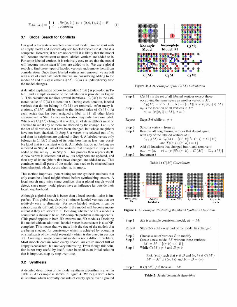
A detailed explanation of how to calculate C(M) is provided in Ta-ble 1 and a simple example of the calculation is provided in Figure3. This calculation requires several iterations. Ct(M) is the esti-mated value of C(M) at iteration t. During each iteration, labeledvertices that do not belong in C(M) are removed. After many it-erations, Ct(M) will be equal to the desired value of C(M). Ateach vertex that has been assigned a label in M , all other labelsare removed in Step 1 since each vertex may only have one label.Whenever Ct(M) changes at a vertex, all of its neighbors must bechecked to see if any of them are affected by the change. Let ut bethe set of all vertices that have been changed, but whose neighborshave not been checked. In Step 3, a vertex v is selected out of ut
and then its neighbors are updated in Step 4. A labeled vertex onlybelongs in Ct(M) if each of its neighbors has at least one possi-ble label that is consistent with it. All labels that do not belong areremoved in Step 4. All of the vertices that changed in Step 4 areadded to the set ut+1 in Step 5. This process then repeats itself.A new vertex is selected out of ut, its neighbors are updated, andthen any of its neighbors that have changed are added to ut. Thiscontinues until all parts of the model that need to be checked havebeen checked, which occurs when ut is empty.
This method improves upon existing texture synthesis methods thatonly examine a local neighborhood before synthesizing texture. Alocal search may miss some conflicts that a global search woulddetect, since many model pieces have an influence far outside theirlocal neighborhood.
Although a global search is better than a local search, it also is im-perfect. This global search only eliminates labeled vertices that arerelatively easy to eliminate. For some labeled vertices, it can beextraordinarily difficult to decide if the model will become incon-sistent if they are added to it. Deciding whether or not a model isconsistent is shown to be an NP-complete problem in the appendix.(This proof applies to both 2D textures and 3D models.) Decidingif a model with an additional labeled vertex is consistent is also NP-complete. This means that we must limit the size of the models thatare being checked for consistency which is achieved by operatingon small parts of the model separately which is discussed in Section3.2. Creating a single consistent model is not a difficult problem.Most models contain some empty space. An entire model full ofempty is consistent, but not very interesting. Even though this solu-tion is not very useful by itself, it can be used as an initial solutionthat is improved step by step over time.
3.2 Synthesis
A detailed description of the model synthesis algorithm is given inTable 2. An example is shown in Figure 4. We begin with a triv-ial solution which normally consists of empty space over a ground
Figure 3: A 2D example of the C(M) Calculation
Step 1: C0(M) is the set of all labeled vertices except thoseoccupying the same space as another vertex in M :
C0(M) = V × [1 . . . N ] − {(v, k)|∃i 6= k, (v, i) ∈ M}Step 2: u0 is the location of all vertices in M :
u0 = {v|(v, i) ∈ M}, t = 0
Repeat Steps 3-6 while ut 6= ∅
Step 3: Select a vertex v from ut
Step 4: Remove all neighboring vertices that do not agreewith any of the labeled vertices at v:
Ct+1(M) = Ct(M) − {(v′, k)|@i, (v, i) ∈ Ct(M)and T ((v, i), (v′, k)) = 1}
Step 5: Add all locations that changed into u and remove v:ut+1 = (ut − v) ∪ {v′|∃k, (v′, k) ∈ Ct(M) − Ct+1(M)}
Step 6: Increment t
Table 1: C(M) Calculation
Figure 4: An example illustrating the Model Synthesis Algorithm.
Step 1: M0 is a simple consistent model, M = M0
Repeat Steps 2-5 until every part of the model has changed:
Step 2: Choose a set of vertices B to modifyStep 3: Create a new model M ′ without those vertices:
M ′ = M − {(v, k)|v ∈ B}Step 4: While C(M ′) 6= ∅ and B 6= ∅
Pick (v, k) such that v ∈ B and (v, k) ∈ C(M ′)M ′ = M ′ ∪ {(v, k)} and B = B − {v}
Step 5: If C(M ′) 6= ∅ then M = M ′
Table 2: Model Synthesis Algorithm
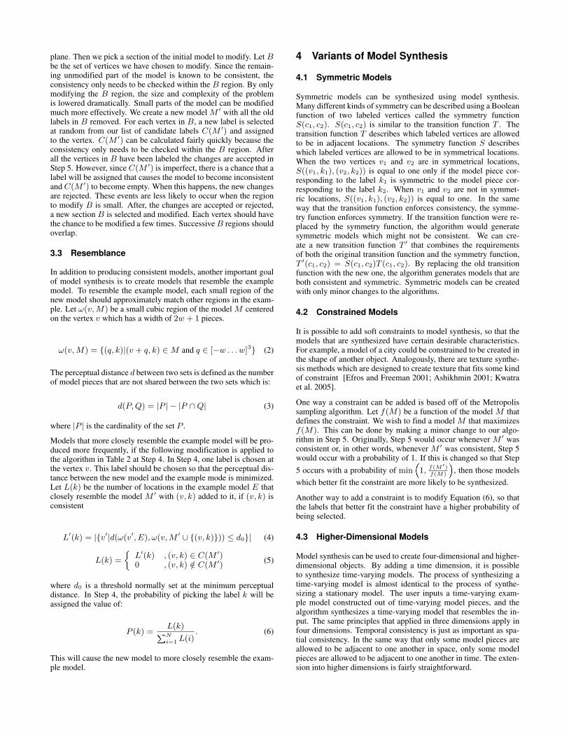
plane. Then we pick a section of the initial model to modify. Let Bbe the set of vertices we have chosen to modify. Since the remain-ing unmodified part of the model is known to be consistent, theconsistency only needs to be checked within the B region. By onlymodifying the B region, the size and complexity of the problemis lowered dramatically. Small parts of the model can be modifiedmuch more effectively. We create a new model M ′ with all the oldlabels in B removed. For each vertex in B, a new label is selectedat random from our list of candidate labels C(M ′) and assignedto the vertex. C(M ′) can be calculated fairly quickly because theconsistency only needs to be checked within the B region. Afterall the vertices in B have been labeled the changes are accepted inStep 5. However, since C(M ′) is imperfect, there is a chance that alabel will be assigned that causes the model to become inconsistentand C(M ′) to become empty. When this happens, the new changesare rejected. These events are less likely to occur when the regionto modify B is small. After, the changes are accepted or rejected,a new section B is selected and modified. Each vertex should havethe chance to be modified a few times. Successive B regions shouldoverlap.
3.3 Resemblance
In addition to producing consistent models, another important goalof model synthesis is to create models that resemble the examplemodel. To resemble the example model, each small region of thenew model should approximately match other regions in the exam-ple. Let ω(v, M) be a small cubic region of the model M centeredon the vertex v which has a width of 2w + 1 pieces.
ω(v, M) = {(q, k)|(v + q, k) ∈ M and q ∈ [−w . . . w]3} (2)
The perceptual distance d between two sets is defined as the numberof model pieces that are not shared between the two sets which is:
d(P, Q) = |P | − |P ∩ Q| (3)
where |P | is the cardinality of the set P .
Models that more closely resemble the example model will be pro-duced more frequently, if the following modification is applied tothe algorithm in Table 2 at Step 4. In Step 4, one label is chosen atthe vertex v. This label should be chosen so that the perceptual dis-tance between the new model and the example mode is minimized.Let L(k) be the number of locations in the example model E thatclosely resemble the model M ′ with (v, k) added to it, if (v, k) isconsistent
L′(k) = |{v′|d(ω(v′, E), ω(v, M ′ ∪ {(v, k)})) ≤ d0}| (4)
L(k) = � L′(k) , (v, k) ∈ C(M ′)0 , (v, k) /∈ C(M ′)
(5)
where d0 is a threshold normally set at the minimum perceptualdistance. In Step 4, the probability of picking the label k will beassigned the value of:
P (k) =L(k)� N
i=1 L(i). (6)
This will cause the new model to more closely resemble the exam-ple model.
4 Variants of Model Synthesis
4.1 Symmetric Models
Symmetric models can be synthesized using model synthesis.Many different kinds of symmetry can be described using a Booleanfunction of two labeled vertices called the symmetry functionS(c1, c2). S(c1, c2) is similar to the transition function T . Thetransition function T describes which labeled vertices are allowedto be in adjacent locations. The symmetry function S describeswhich labeled vertices are allowed to be in symmetrical locations.When the two vertices v1 and v2 are in symmetrical locations,S((v1, k1), (v2, k2)) is equal to one only if the model piece cor-responding to the label k1 is symmetric to the model piece cor-responding to the label k2. When v1 and v2 are not in symmet-ric locations, S((v1, k1), (v2, k2)) is equal to one. In the sameway that the transition function enforces consistency, the symme-try function enforces symmetry. If the transition function were re-placed by the symmetry function, the algorithm would generatesymmetric models which might not be consistent. We can cre-ate a new transition function T ′ that combines the requirementsof both the original transition function and the symmetry function,T ′(c1, c2) = S(c1, c2)T (c1, c2). By replacing the old transitionfunction with the new one, the algorithm generates models that areboth consistent and symmetric. Symmetric models can be createdwith only minor changes to the algorithms.
4.2 Constrained Models
It is possible to add soft constraints to model synthesis, so that themodels that are synthesized have certain desirable characteristics.For example, a model of a city could be constrained to be created inthe shape of another object. Analogously, there are texture synthe-sis methods which are designed to create texture that fits some kindof constraint [Efros and Freeman 2001; Ashikhmin 2001; Kwatraet al. 2005].
One way a constraint can be added is based off of the Metropolissampling algorithm. Let f(M) be a function of the model M thatdefines the constraint. We wish to find a model M that maximizesf(M). This can be done by making a minor change to our algo-rithm in Step 5. Originally, Step 5 would occur whenever M ′ wasconsistent or, in other words, whenever M ′ was consistent, Step 5would occur with a probability of 1. If this is changed so that Step5 occurs with a probability of min � 1, f(M′)
f(M) , then those modelswhich better fit the constraint are more likely to be synthesized.
Another way to add a constraint is to modify Equation (6), so thatthe labels that better fit the constraint have a higher probability ofbeing selected.
4.3 Higher-Dimensional Models
Model synthesis can be used to create four-dimensional and higher-dimensional objects. By adding a time dimension, it is possibleto synthesize time-varying models. The process of synthesizing atime-varying model is almost identical to the process of synthe-sizing a stationary model. The user inputs a time-varying exam-ple model constructed out of time-varying model pieces, and thealgorithm synthesizes a time-varying model that resembles the in-put. The same principles that applied in three dimensions apply infour dimensions. Temporal consistency is just as important as spa-tial consistency. In the same way that only some model pieces areallowed to be adjacent to one another in space, only some modelpieces are allowed to be adjacent to one another in time. The exten-sion into higher dimensions is fairly straightforward.
(a) (b) (c)
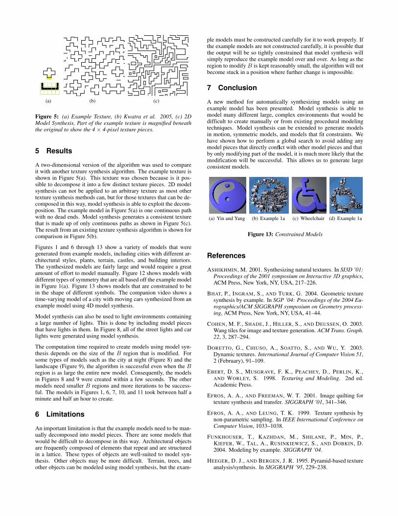
Figure 5: (a) Example Texture, (b) Kwatra et al. 2005, (c) 2DModel Synthesis, Part of the example texture is magnified beneaththe original to show the 4 × 4-pixel texture pieces.
5 Results
A two-dimensional version of the algorithm was used to compareit with another texture synthesis algorithm. The example texture isshown in Figure 5(a). This texture was chosen because is it pos-sible to decompose it into a few distinct texture pieces. 2D modelsynthesis can not be applied to an arbitrary texture as most othertexture synthesis methods can, but for those textures that can be de-composed in this way, model synthesis is able to exploit the decom-position. The example model in Figure 5(a) is one continuous pathwith no dead ends. Model synthesis generates a consistent texturethat is made up of only continuous paths as shown in Figure 5(c).The result from an existing texture synthesis algorithm is shown forcomparison in Figure 5(b).
Figures 1 and 6 through 13 show a variety of models that weregenerated from example models, including cities with different ar-chitectural styles, plants, terrain, castles, and building interiors.The synthesized models are fairly large and would require a greatamount of effort to model manually. Figure 12 shows models withdifferent types of symmetry that are all based off the example modelin Figure 1(a). Figure 13 shows models that are constrained to bein the shape of different symbols. The companion video shows atime-varying model of a city with moving cars synthesized from anexample model using 4D model synthesis.
Model synthesis can also be used to light environments containinga large number of lights. This is done by including model piecesthat have lights in them. In Figure 8, all of the street lights and carlights were generated using model synthesis.
The computation time required to create models using model syn-thesis depends on the size of the B region that is modified. Forsome types of models such as the city at night (Figure 8) and thelandscape (Figure 9), the algorithm is successful even when the Bregion is as large the entire new model. Consequently, the modelsin Figures 8 and 9 were created within a few seconds. The othermodels need smaller B regions and more iterations to be success-ful. The models in Figures 1, 6, 7, 10, and 11 took between half aminute and half an hour to create.
6 Limitations
An important limitation is that the example models need to be man-ually decomposed into model pieces. There are some models thatwould be difficult to decompose in this way. Architectural objectsare frequently composed of elements that repeat and are structuredin a lattice. These types of objects are well-suited to model syn-thesis. Other objects may be more difficult. Terrain, trees, andother objects can be modeled using model synthesis, but the exam-
ple models must be constructed carefully for it to work properly. Ifthe example models are not constructed carefully, it is possible thatthe output will be so tightly constrained that model synthesis willsimply reproduce the example model over and over. As long as theregion to modify B is kept reasonably small, the algorithm will notbecome stuck in a position where further change is impossible.
7 Conclusion
A new method for automatically synthesizing models using anexample model has been presented. Model synthesis is able tomodel many different large, complex environments that would bedifficult to create manually or from existing procedural modelingtechniques. Model synthesis can be extended to generate modelsin motion, symmetric models, and models that fit constraints. Wehave shown how to perform a global search to avoid adding anymodel pieces that directly conflict with other model pieces and thatby only modifying part of the model, it is much more likely that themodification will be successful. This allows us to generate largeconsistent models.
(a) Yin and Yang (b) Example 1a (c) Wheelchair (d) Example 1a
Figure 13: Constrained Models
References
ASHIKHMIN, M. 2001. Synthesizing natural textures. In SI3D ’01:Proceedings of the 2001 symposium on Interactive 3D graphics,ACM Press, New York, NY, USA, 217–226.
BHAT, P., INGRAM, S., AND TURK, G. 2004. Geometric texturesynthesis by example. In SGP ’04: Proceedings of the 2004 Eu-rographics/ACM SIGGRAPH symposium on Geometry process-ing, ACM Press, New York, NY, USA, 41–44.
COHEN, M. F., SHADE, J., HILLER, S., AND DEUSSEN, O. 2003.Wang tiles for image and texture generation. ACM Trans. Graph.22, 3, 287–294.
DORETTO, G., CHIUSO, A., SOATTO, S., AND WU, Y. 2003.Dynamic textures. International Journal of Computer Vision 51,2 (February), 91–109.
EBERT, D. S., MUSGRAVE, F. K., PEACHEY, D., PERLIN, K.,AND WORLEY, S. 1998. Texturing and Modeling. 2nd ed.Academic Press.
EFROS, A. A., AND FREEMAN, W. T. 2001. Image quilting fortexture synthesis and transfer. SIGGRAPH ’01, 341–346.
EFROS, A. A., AND LEUNG, T. K. 1999. Texture synthesis bynon-parametric sampling. In IEEE International Conference onComputer Vision, 1033–1038.
FUNKHOUSER, T., KAZHDAN, M., SHILANE, P., MIN, P.,KIEFER, W., TAL, A., RUSINKIEWICZ, S., AND DOBKIN, D.2004. Modeling by example. SIGGRAPH ’04.
HEEGER, D. J., AND BERGEN, J. R. 1995. Pyramid-based textureanalysis/synthesis. In SIGGRAPH ’95, 229–238.
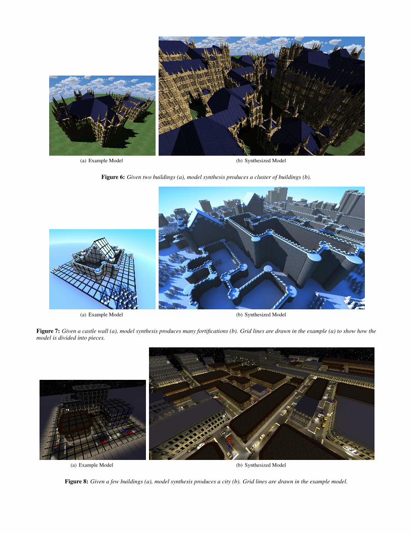
(a) Example Model (b) Synthesized Model
Figure 6: Given two buildings (a), model synthesis produces a cluster of buildings (b).
(a) Example Model (b) Synthesized Model
Figure 7: Given a castle wall (a), model synthesis produces many fortifications (b). Grid lines are drawn in the example (a) to show how themodel is divided into pieces.
(a) Example Model (b) Synthesized Model
Figure 8: Given a few buildings (a), model synthesis produces a city (b). Grid lines are drawn in the example model.
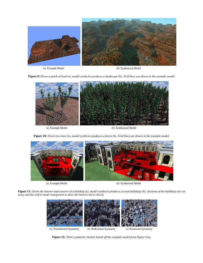
(a) Example Model (b) Synthesized Model
Figure 9: Given a patch of land (a), model synthesis produces a landscape (b). Grid lines are drawn in the example model.
(a) Example Model (b) Synthesized Model
Figure 10: Given two trees (a), model synthesis produces a forest (b). Grid lines are drawn in the example model.
(a) Example Model (b) Synthesized Model
Figure 11: Given the interior and exterior of a building (a), model synthesis produces several buildings (b). Sections of the buildings are cutaway and the roof is made transparent to show the interior more clearly.
(a) Translational Symmetry (b) Reflectional Symmetry (c) Rotational Symmetry
Figure 12: Three symmetric models based off the example model from Figure 1(a).
II, K. C., AND KARI, J. 1996. An aperiodic set of wang cubes. InSymposium on Theoretical Aspects of Computer Science, 137–146.
KWATRA, V., SCHDL, A., ESSA, I., TURK, G., AND BOBICK, A.2003. Graphcut textures: Image and video synthesis using graphcuts. SIGGRAPH ’03, 277–286.
KWATRA, V., ESSA, I., BOBICK, A., AND KWATRA, N. 2005.Texture optimization for example-based synthesis. SIGGRAPH’05.
LEGAKIS, J., DORSEY, J., AND GORTLER, S. 2001. Feature-based cellular texturing for architectural models. In SIGGRAPH’01, 309–316.
LU, A., EBERT, D. S., QIAO, W., KRAUS, M., AND MORA, B.2004. Interactive Volume Illustration Using Wang Cubes. Tech.Rep. TR-ECE-04-05, Purdue University.
MECH, R., AND PRUSINKIEWICZ, P. 1996. Visual models ofplants interacting with their environment. In SIGGRAPH ’96,397–410.
MULLER, P., WONKA, P., HAEGLER, S., ULMER, A., ANDGOOL, L. V. 2006. Procedural modeling of buildings. ACMTrans. Graph. 25, 3, 614–623.
MUSGRAVE, F. K., KOLB, C. E., AND MACE, R. S. 1989. Thesynthesis and rendering of eroded fractal terrains. In SIGGRAPH’89, 41–50.
PORTILLA, J., AND SIMONCELLI, E. P. 2000. A parametric tex-ture model based on joint statistics of complex wavelet coeffi-cients. International Journal of Computer Vision 40, 1, 49–70.
PRUSINKIEWICZ, P., MUNDERMANN, L., KARWOWSKI, R., ANDLANE, B. 2001. The use of positional information in the mod-eling of plants. In SIGGRAPH ’01, 289–300.
SHARF, A., ALEXA, M., AND COHEN-OR, D. 2004. Context-based surface completion. SIGGRAPH ’04, 878–887.
SIBLEY, P., MONTGOMERY, P., AND MARAI, G. E., 2004. Wangcubes for video synthesis and geometry placement. ACM SIG-GRAPH 2004 Poster Compendium, August.
WEI, L.-Y., AND LEVOY, M. 2000. Fast texture synthesis us-ing tree-structured vector quantization. In SIGGRAPH ’00, 479–488.
A Deciding if a Texture can be Completed isan NP-Complete Problem
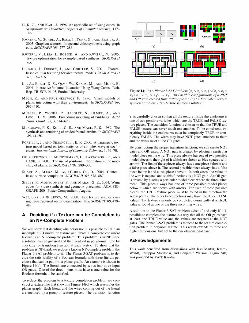
We will show that deciding whether or not it is possible to fill in anincomplete 2D model or texture and create a complete consistenttexture is an NP-complete problem. This problem is in NP sincea solution can be guessed and then verified in polynomial time bychecking the transition function at each vertex. To show that theproblem is NP-hard, we reduce a known NP-complete problem thePlanar 3-SAT problem to it. The Planar 3-SAT problem is to de-cide the satisfiability of a Boolean formula with three literals perclause that can be put into a planar graph. An example is shown inFigure 14(a). The literals are connected by wires into three-inputOR gates. One of the three inputs must have a true value for theBoolean formula to be satisfied.
To reduce the problem to a texture completion problem, we con-struct a texture like that shown in Figure 14(c) which resembles theplanar graph. Each literal and the wires coming out of the literalare enclosed by a group of texture pieces. The transition function
(a) (b)
(c) (d)
Figure 14: (a) A Planar 3-SAT Problem (x1∨x2∨x4)∧(x2∨x3∨x4) ∧ (∼ x1 ∨ x2∨ ∼ x4), (b) Possible configurations of a NOTand OR gate created from texture pieces, (c) An Equivalent texturesynthesis problem, (d) A texture synthesis solution
T is carefully chosen so that all the texture inside the enclosure isone of two possible varieties which are the TRUE and FALSE tex-ture pieces. The transition function is chosen so that the TRUE andFALSE texture can never touch one another. To be consistent, ev-erything inside the enclosures must be completely TRUE or com-pletely FALSE. The wires may have NOT gates attached to themand the wires meet at the OR gates.
By constructing the proper transition function, we can create NOTgates and OR gates. A NOT gate is created by placing a particularmodel piece on the wire. This piece always has one of two possiblemodel pieces to the right of it which are shown as blue squares witharrows. The first of these pieces always has a true piece below it anda false piece above it. The second possible piece always has a falsepiece below it and a true piece above it. In both cases, the value onthe wire is negated and so this functions as a NOT gate. An OR gateis created by placing a particular model piece where the three wiresmeet. This piece always has one of three possible model piecesbelow it which are shown with arrows. For each of these possiblepieces, the TRUE texture piece must be found in the direction thearrow points. The other two directions may have TRUE or FALSEvalues. The texture can only be completed consistently if a TRUEvalue is found at one of the three incoming wires.
A solution to the Planar 3-SAT problem exists if and only if it ispossible to complete the texture in a way that all the OR gates haveat least one TRUE value and the values are negated at the NOTgates. The Planar 3-SAT problem is reduced to the texture comple-tion problem in polynomial time. This result extends to three andhigher dimensions, but not to the one-dimensional case.
Acknowledgements
This work benefited from discussions with Jess Martin, JeremyWendt, Philippos Mordohai, and Benjamin Watson. Figure 5(b)was provided by Vivek Kwatra.