excavation procedure number: cpl hes- · pdf fileexcavation procedure number: cpl hes-202 ....
TRANSCRIPT
EXCAVATION
PROCEDURE NUMBER: CPL HES-202 Approved December 2011 Version 1.2
CPL –HES 202 Excavation
Version 1.2. Revised December 2011. 2 Printed 16 April 2012. Uncontrolled when printed. CPL HES 202 Excavation
CONTENTS
EXCAVATION HES-202
Section Title Page
1.0 Purpose 202 - 3
2.0 Scope 202 - 3
3.0 Prerequisites 202 - 3
4.0 Process Overview 202 - 5
5.0 Instructions 202 - 10
5.1 Preparation for Excavation 202 - 10
5.2 Job Site Preparation
202 - 12
5.3 Non-Entry Excavations
202 - 12
5.4 Excavations Involving Entry
202 - 13
5.5 Determine Soil Type
202 - 13
5.6 Determine Protective System
202 - 13
5.7 Complete Excavation Permit
202 - 18
5.8 Excavation Work
202 - 19
5.9 Permit Extension
202 - 20
5.10 Work Completion
202 - 20
6.0 Roles and Responsibility 202 - 20
7.0 Reporting Requirements 202 - 22
8.0 Documentation and Records Retention 202 - 22
Appendices
A Glossary
B Excavation Permit
C Shoring Requirements
D To Identifying the Location of Underground Utilities Prior to Excavating
CPL –HES 202 Excavation
Version 1.2. Revised December 2011. 3 Printed 16 April 2012. Uncontrolled when printed. CPL HES 202 Excavation
1.0 Purpos e This procedure is written to:
• describe the methods used to assist in protecting employees, company representatives, and the public from injury during excavation activities;
• minimize the risk of damage to structures and facilities during excavations; and
• verify compliance with Occupational Safety and Health Administration (OSHA) requirements contained in 29 CFR 1926.650 through 652; with Department of Transportation (DOT) requirements contained in 49 CFR 195.402; with CAL OSHA 8 CCR 341.1 (f) and other state regulations regarding excavation.
2.0 Scope
2.1 Personnel and Activities Covered by this Procedure This procedure applies to excavations performed and/or coordinated by all personnel, company or contractor, working in or on Chevron Pipe Line Company (CPL) owned, operated, managed, or maintained pipelines or facilities.
This procedure covers activities whenever the ground is broken for open excavations (e.g., trenching, pile driving, ground water wells, soil boring, installation of pipelines, conduit, foundations, etc.).
2.2 Exemptions from this Procedure Excavations performed underwater are exempt from this procedure. If you need assistance in developing work plans for excavations underwater, contact your local Safety Specialist.
3.0 Prerequis ites
3.1 Training/Personnel Requirements • Persons identified as the “Person-In-Charge” (PIC) must be trained in this
procedure.
• All excavations involving worker entry require a Competent Person on site. A competent person is an individual who is trained in and knowledgeable about soil analysis, the use of protective systems, and the requirements of the OSHA Construction Standard 29 CFR 1926.650. A Competent Person must be capable of identifying existing and predictable hazards in excavation work and have the authority to take prompt measures to abate these hazards. In California, the Competent Person must know CAL OSHA Standards. The knowledge and understanding of this procedure alone does not make someone a competent
CPL –HES 202 Excavation
Version 1.2. Revised December 2011. 4 Printed 16 April 2012. Uncontrolled when printed. CPL HES 202 Excavation
person. To become a competent person, one must obtain training via a third party Competent Person training course. Contact the Learning and Development Coordinator for further information.
• Excavations in excess of 20 feet in depth must be designed by a Registered Professional Engineer
• A Registered Professional Engineer is required to approve the integrity of all excavations beneath the level of an adjacent foundation, retaining wall, or other structure including sidewalks.
• Standbys must be trained in Cardiopulmonary Resuscitation, first-aid, and blood-borne pathogen safety.
3.2 Additional Documents The Competent Person or registered professional engineer must comprehend and comply with all applicable sections of 29 CFR 1926.650 through 652.
3.3 California Requirements • CPL must have a California Annual Excavation Permit.
• The Competent Person must know CAL OSHA standards.
• Contractor(s) performing excavation must have a California Annual Excavation Permit.
CPL –HES 202 Excavation
Version 1.2. Revised December 2011. 5 Printed 16 April 2012. Uncontrolled when printed. CPL HES 202 Excavation
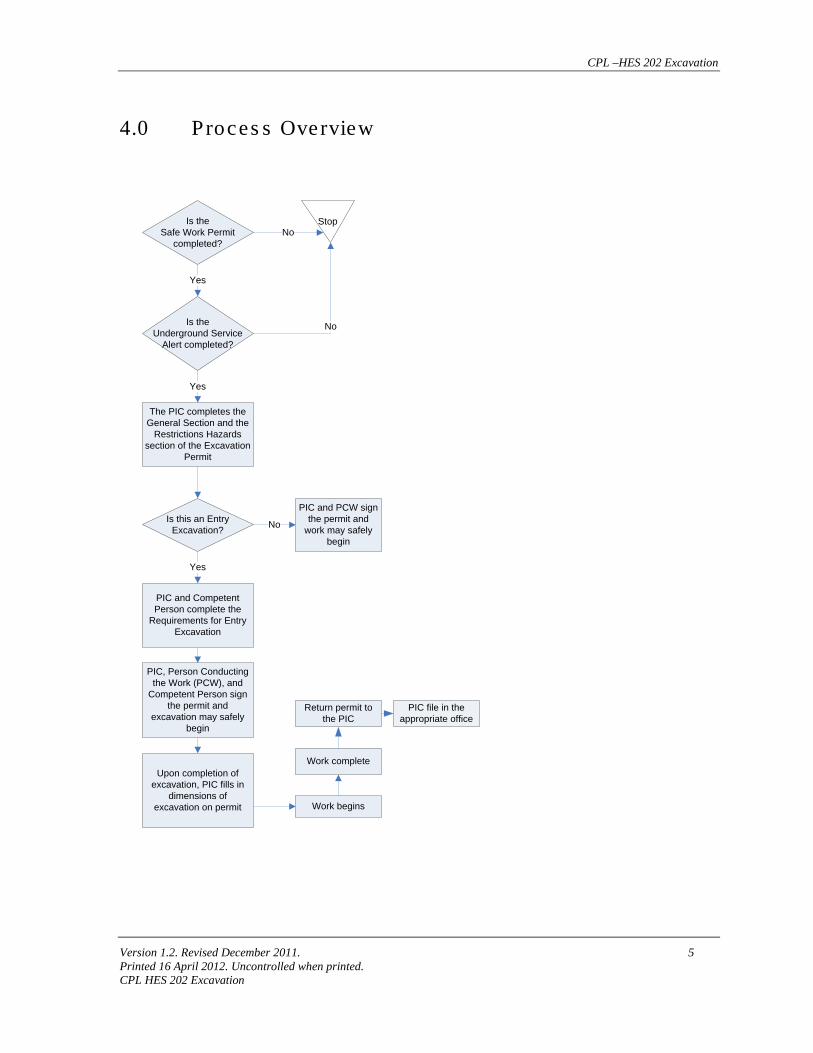
4.0 Proces s Overview
Is theSafe Work Permit
completed?
StopNo
Is theUnderground Service
Alert completed?
No
Yes
The PIC completes the General Section and the
Restrictions Hazards section of the Excavation
Permit
Yes
Is this an Entry Excavation?
PIC and PCW sign the permit and
work may safely begin
PIC and Competent Person complete the
Requirements for Entry Excavation
Yes
No
PIC, Person Conducting the Work (PCW), and
Competent Person sign the permit and
excavation may safely begin
Upon completion of excavation, PIC fills in
dimensions of excavation on permit Work begins
Work complete
PIC file in the appropriate office
Return permit to the PIC
CPL –HES 202 Excavation
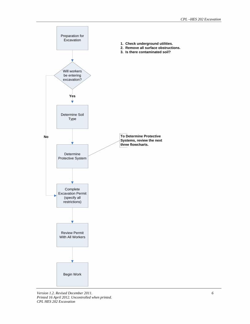
Version 1.2. Revised December 2011. 6 Printed 16 April 2012. Uncontrolled when printed. CPL HES 202 Excavation
Preparation for Excavation
Will workersbe entering excavation?
Determine Soil Type
Determine Protective System
Complete Excavation Permit
(specify all restrictions)
Review Permit With All Workers
Begin Work
1. Check underground utilities.2. Remove all surface obstructions.3. Is there contaminated soil?
Yes
No To Determine Protective Systems, review the next three flowcharts.
CPL –HES 202 Excavation
Version 1.2. Revised December 2011. 7 Printed 16 April 2012. Uncontrolled when printed. CPL HES 202 Excavation
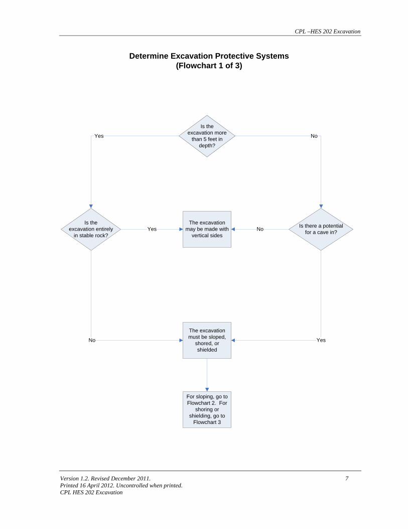
Is the excavation more
than 5 feet in depth?
The excavation may be made with
vertical sides
The excavation must be sloped,
shored, or shielded
For sloping, go to Flowchart 2. For
shoring or shielding, go to
Flowchart 3
Is the excavation entirely
in stable rock?
Is there a potential for a cave in?
Determine Excavation Protective Systems(Flowchart 1 of 3)
Yes
No
No
Yes
Yes No
CPL –HES 202 Excavation
Version 1.2. Revised December 2011. 8 Printed 16 April 2012. Uncontrolled when printed. CPL HES 202 Excavation
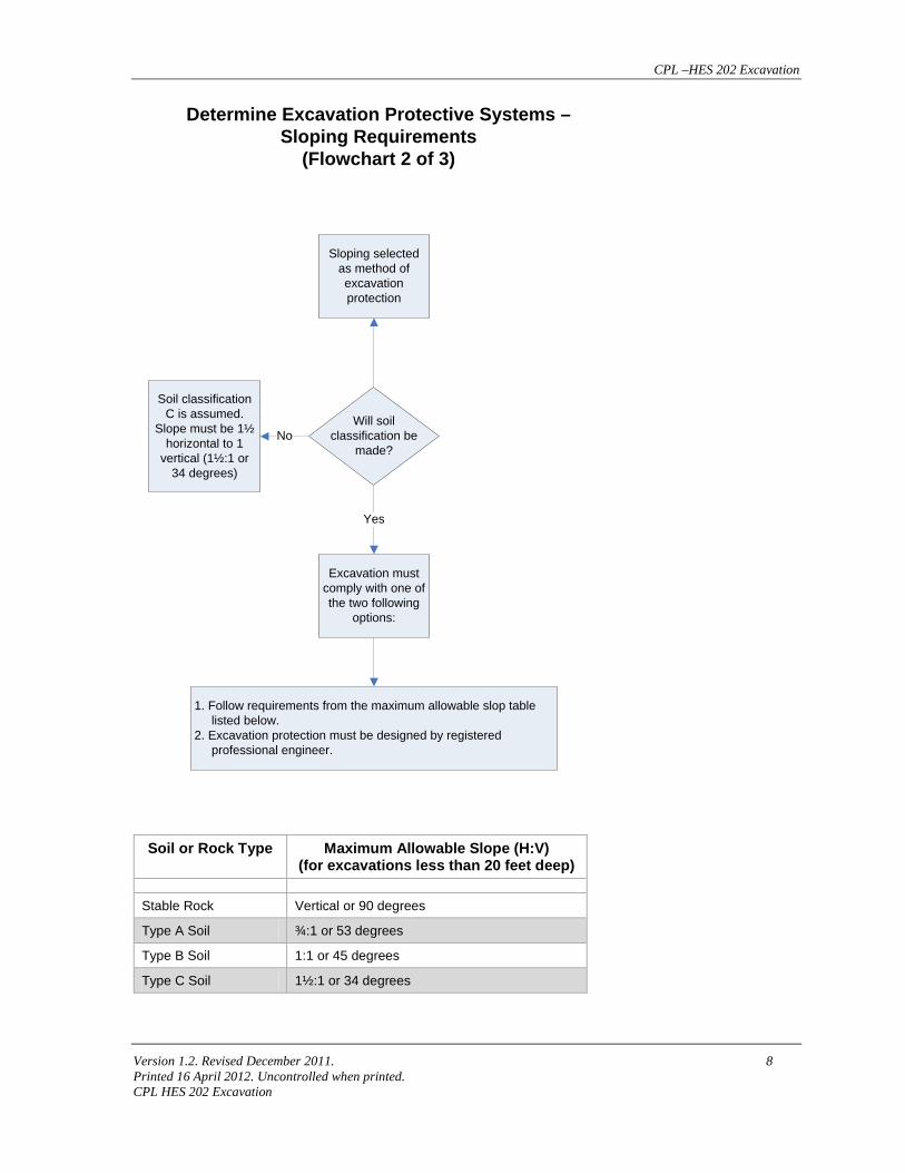
Sloping selected as method of excavation protection
Soil classification C is assumed.
Slope must be 1½ horizontal to 1
vertical (1½:1 or 34 degrees)
Excavation must comply with one of the two following
options:
Will soil classification be
made?
Determine Excavation Protective Systems – Sloping Requirements
(Flowchart 2 of 3)
No
Yes
1. Follow requirements from the maximum allowable slop table listed below.2. Excavation protection must be designed by registered professional engineer.
Soil or Rock Type Maximum Allowable Slope (H:V) (for excavations less than 20 feet deep)
Stable Rock Vertical or 90 degrees
Type A Soil ¾:1 or 53 degrees
Type B Soil 1:1 or 45 degrees
Type C Soil 1½:1 or 34 degrees
CPL –HES 202 Excavation
Version 1.2. Revised December 2011. 9 Printed 16 April 2012. Uncontrolled when printed. CPL HES 202 Excavation
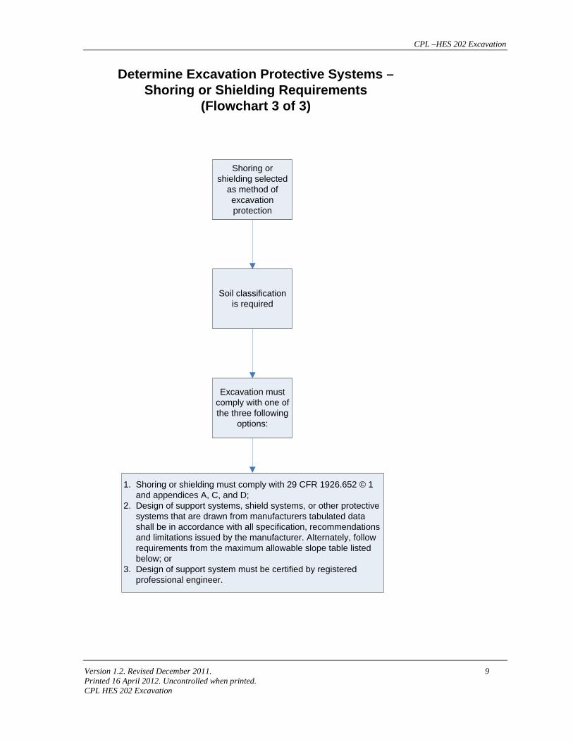
Shoring or shielding selected
as method of excavation protection
Soil classification is required
Excavation must comply with one of the three following
options:
Determine Excavation Protective Systems – Shoring or Shielding Requirements
(Flowchart 3 of 3)
1. Shoring or shielding must comply with 29 CFR 1926.652 © 1 and appendices A, C, and D; 2. Design of support systems, shield systems, or other protective systems that are drawn from manufacturers tabulated data shall be in accordance with all specification, recommendations and limitations issued by the manufacturer. Alternately, follow requirements from the maximum allowable slope table listed below; or3. Design of support system must be certified by registered professional engineer.
CPL –HES 202 Excavation
Version 1.2. Revised December 2011. 10 Printed 16 April 2012. Uncontrolled when printed. CPL HES 202 Excavation
5.0 Ins truc tions
5.1 Preparation for Excavation
5.1.1 The Person-In-Charge (PIC) completes the general section of the Safe Work Permit. The PIC must specify:
a) Facility and location of the excavation;
b) Date of the excavation;
c) Time limits of the excavation;
d) Personnel who will be conducting the work;
e) Description of the work;
f) Equipment to be used; and
g) Job boundaries.
5.1.2 The PIC determines if the excavation will be entry or non-entry and checks the appropriate box on the Excavation Permit. The PIC will then review the area around the proposed excavation site prior to commencing excavation activities to identify and alleviate hazardous conditions including:
a) Soil classification
b) Surface encumbrances
c) Location and identity of utilities
d) Amount of surface and subsurface water present
e) Traffic and nearby structures
f) Depth of excavation
g) Length of time the excavation will be open
h) Climatic conditions
i) Access and egress
The PIC specifies the excavation work site hazards by checking all applicable boxes in the Hazard section of the Excavation Permit.
The PIC must contact the appropriate state, regional, and/or local One-Call Center to notify other pipeline and utility companies. The PIC will notify the One-Call Center of the proposed work and ask to establish the location of underground installations prior to the start of any actual excavation. See Appendix D for instructions on contacting the One-Call Center. 811 is
CPL –HES 202 Excavation
Version 1.2. Revised December 2011. 11 Printed 16 April 2012. Uncontrolled when printed. CPL HES 202 Excavation
the national call before you dig number and is established for most underground utilities. However, some utilities are exempt from participating in the one-call system and may or may-not be active where you are located. All means must be taken to notify the underground asset owners.
5.1.3 When other pipeline and/or utility companies cannot respond to a request to locate underground utility installations within 48 hours (unless a longer time period is required by state or local law), or cannot establish the exact location of these installations by attempts to contact these companies directly, the PIC may authorize the excavation to proceed, provided company does so with caution and provided detection equipment or other acceptable means to locate underground installations are employed.
In addition, all obstructions, both above and underground, must be identified and marked before excavation work begins.
The PIC must review all available maps, plans, and drawings for buried conduits, cables, and piping that may run through or within the vicinity of the proposed excavation and work area.
5.1.4 The PIC must obtain all applicable state and/or local required permits.
Employees in California must notify a CAL OSHA office at least one week prior to commencement of job if excavation will be over five feet deep OR if a Chevron employee will be going in an excavation made by a contractor. Notification by telephone must be followed up in writing on “Activity Notification Form for holders of permit.” These are available from any CAL OSHA office.
5.1.5 The PIC must also make arrangements to close the roadway and detour traffic if the excavation will adversely affect a roadway.
5.1.6 After a review of the excavation site, the PIC will determine which additional safety requirements must be met. The following is a list of safety precautions which may apply to a particular excavation:
a) Workers exposed to vehicular traffic must be provided with and wear warning vests or other suitable garments marked with or made of reflective or high visibility material. This reflective or high visibility vest must conform to CPL’s FRC policy.
b) All surface obstructions (such as piping, posts, etc.) that create a hazard to employees must be removed or supported to safeguard employees.
c) Excavations beneath the level of an adjacent foundation, retaining wall, or other structure including sidewalks, are not allowed until a Registered Professional Engineer has determined that the work will not undermine the structures.
CPL –HES 202 Excavation
Version 1.2. Revised December 2011. 12 Printed 16 April 2012. Uncontrolled when printed. CPL HES 202 Excavation
d) Warning systems (such as barricades, stop logs, hand or mechanical signals) must be utilized to warn against mobile equipment operating close to the excavation.
e) When personnel crossings over the excavation are required or permitted, OSHA approved crossings will be used including toe boards and guardrails.
f) Barricades or barriers must be provided at all excavations.
g) Covers placed over open trenches in roadways must be designed by a Registered Professional Engineer and secured against movement.
h) A standby with safety and rescue equipment may be required on site.
The PIC may specify any other restrictions or approvals as deemed necessary.
5.1.7 The PIC specifies the required restriction(s) by checking all applicable boxes in the Permit Restriction section of the Excavation Permit. Once the restrictions have been specified, the PIC signs on the Restrictions are specified line of the permit.
5.2 Job Site Preparation
5.2.1 The PIC and the Person Conducting the Work (PCW) shall review the work details, job site, and permit conditions to assure the work is defined and can be done safely.
5.2.2 The PCW satisfies all required precautions and restrictions and obtains any additional approvals.
5.3 Non-Entry Excavations Excavation not involving entry may begin and continue until completed, under the following conditions:
a) No personnel are allowed in the excavation unless the entry requirements of section 5.4 Excavations Involving Entry have been met.
b) While the excavation is open, underground installations must be protected, supported, or removed.
c) No workers are permitted underneath loads handled by lifting or digging equipment. Personnel are required to stand away from any vehicle being loaded or unloaded to avoid being struck by any spillage or falling material.
d) Accumulations of water which could endanger the excavation must be removed and the source of water controlled before allowing further work.
e) Any damaged structure(s) or equipment must be evaluated by a Competent Person and removed from service if unsuitable for use.
CPL –HES 202 Excavation
Version 1.2. Revised December 2011. 13 Printed 16 April 2012. Uncontrolled when printed. CPL HES 202 Excavation
f) When excavating within five feet of an underground pipeline or conduit, the location of the pipeline or conduit must be precisely located by hand-digging (or probing) the last two feet (see MIP-206). After pipeline or conduit has been located, power driven equipment may be used under the following conditions:
o A representative of the pipeline or conduit owner has been notified and is either present or declines to watch the excavation;
o It has been positively determined that any electrical conduit is safely encased in a concrete envelope; or
o Person-in-Charge authorizes the work to continue using power driven equipment.
5.4 Excavations Involving Entry If employees will be required to enter the excavation, the PIC must have a Competent Person examine and classify the soil conditions to determine the appropriate protective system to be used.
Footing excavations, bell bottom pier holes or other confined excavations require the use of the Confined Space Entry procedure (HES-201) and permit. A harness with lifeline securely attached must be individually attended at all times while the employee wearing the lifeline is in the excavation.
5.5 Determine Soil Type
5.5.1 The Competent Person classifies the soil type using both the accepted visual and manual tests per OSHA Standard 29 CFR 1926.652 Appendix A.
5.5.2 The Competent Person records the type of soil and the soil test method on the appropriate section of the Excavation Permit.
5.6 Determine Protective Systems
5.6.1 The Competent Person and the PIC determine the type of protective system to be used, benching, sloping, shielding, timber shoring, or aluminum hydraulic shoring.
Sloping, benching, or support systems for an excavation greater than 20 feet deep must be designed by a Registered Professional Engineer.
5.6.2 The PIC records the type of protective system used at the site on the appropriate section of the Excavation Permit. The excavation dimensions, length, width, and depth are also recorded.
5.6.3 The Competent Person may exempt the excavation from the requirements for shoring, benching, and sloping if:
CPL –HES 202 Excavation
Version 1.2. Revised December 2011. 14 Printed 16 April 2012. Uncontrolled when printed. CPL HES 202 Excavation
• Excavation is less than five feet deep, there is no potential for cave-in (four feet in Washington and Oregon); or
• Excavation is made entirely in stable rock that has no potential for collapse and decision is documented on form CPL-687.
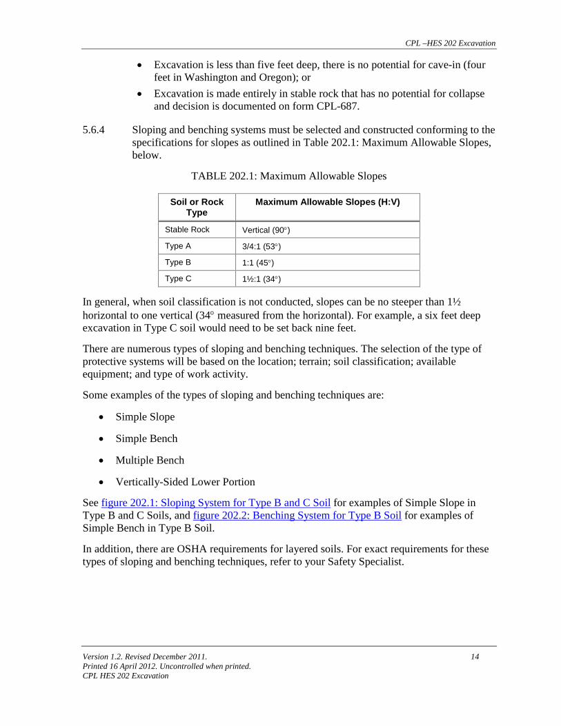
5.6.4 Sloping and benching systems must be selected and constructed conforming to the specifications for slopes as outlined in Table 202.1: Maximum Allowable Slopes, below.
TABLE 202.1: Maximum Allowable Slopes
Soil or Rock Type
Maximum Allowable Slopes (H:V)
Stable Rock Vertical (90°)
Type A 3/4:1 (53°)
Type B 1:1 (45°)
Type C 1½:1 (34°)
In general, when soil classification is not conducted, slopes can be no steeper than 1½ horizontal to one vertical (34° measured from the horizontal). For example, a six feet deep excavation in Type C soil would need to be set back nine feet.
There are numerous types of sloping and benching techniques. The selection of the type of protective systems will be based on the location; terrain; soil classification; available equipment; and type of work activity.
Some examples of the types of sloping and benching techniques are:
• Simple Slope
• Simple Bench
• Multiple Bench
• Vertically-Sided Lower Portion
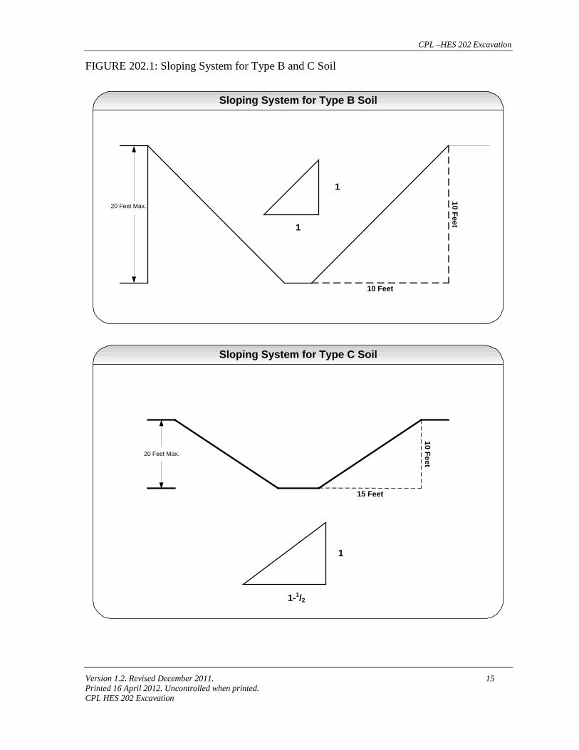
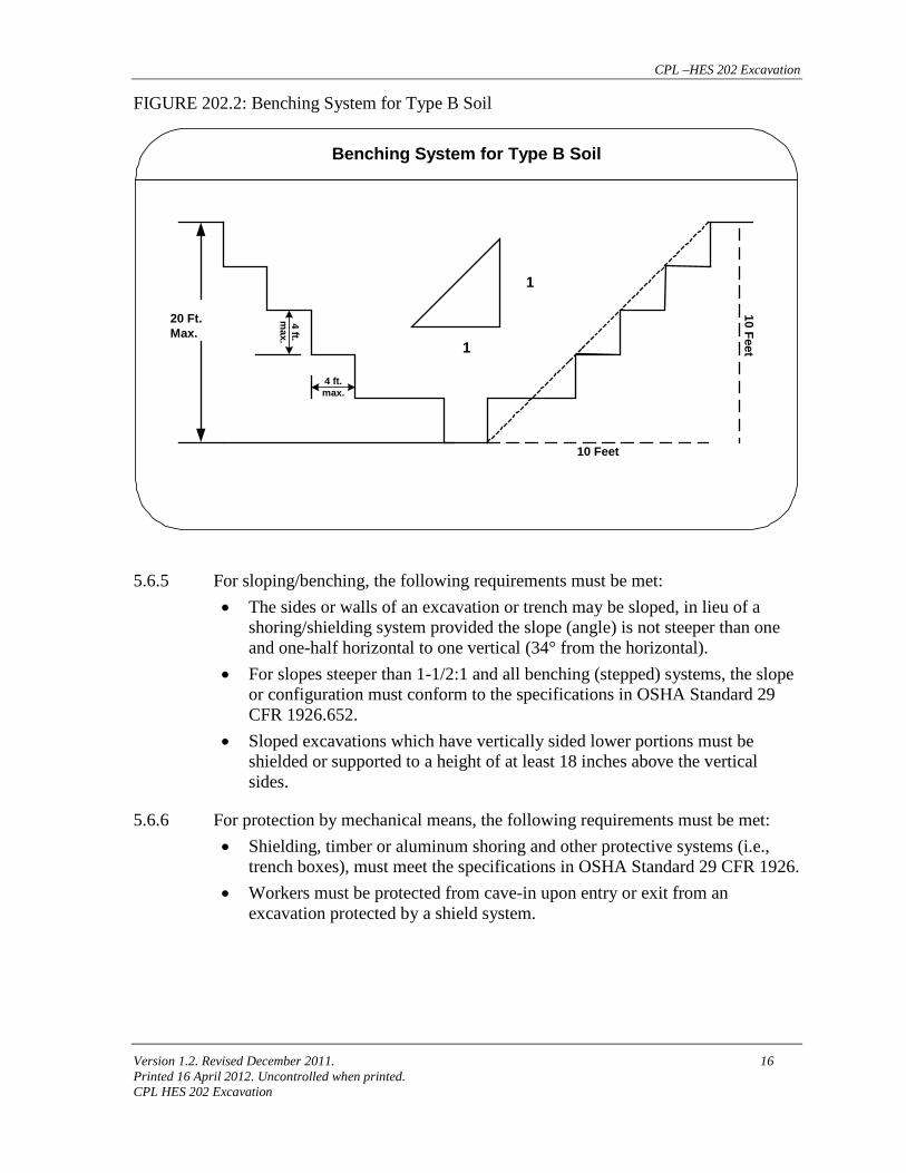
See figure 202.1: Sloping System for Type B and C Soil for examples of Simple Slope in Type B and C Soils, and figure 202.2: Benching System for Type B Soil for examples of Simple Bench in Type B Soil.
In addition, there are OSHA requirements for layered soils. For exact requirements for these types of sloping and benching techniques, refer to your Safety Specialist.
CPL –HES 202 Excavation
Version 1.2. Revised December 2011. 15 Printed 16 April 2012. Uncontrolled when printed. CPL HES 202 Excavation
FIGURE 202.1: Sloping System for Type B and C Soil
20 Feet Max.
1
1
10 Feet
10 Feet
Sloping System for Type B Soil
Sloping System for Type C Soil
20 Feet Max.
10 Feet
15 Feet
1
1-1/2
CPL –HES 202 Excavation
Version 1.2. Revised December 2011. 16 Printed 16 April 2012. Uncontrolled when printed. CPL HES 202 Excavation
FIGURE 202.2: Benching System for Type B Soil
20 Ft.Max.
1
1
10 Feet
10 Feet
Benching System for Type B Soil
4 ft.m
ax.
4 ft.max.
5.6.5 For sloping/benching, the following requirements must be met: • The sides or walls of an excavation or trench may be sloped, in lieu of a
shoring/shielding system provided the slope (angle) is not steeper than one and one-half horizontal to one vertical (34° from the horizontal).
• For slopes steeper than 1-1/2:1 and all benching (stepped) systems, the slope or configuration must conform to the specifications in OSHA Standard 29 CFR 1926.652.
• Sloped excavations which have vertically sided lower portions must be shielded or supported to a height of at least 18 inches above the vertical sides.
5.6.6 For protection by mechanical means, the following requirements must be met: • Shielding, timber or aluminum shoring and other protective systems (i.e.,
trench boxes), must meet the specifications in OSHA Standard 29 CFR 1926. • Workers must be protected from cave-in upon entry or exit from an
excavation protected by a shield system.
CPL –HES 202 Excavation
Version 1.2. Revised December 2011. 17 Printed 16 April 2012. Uncontrolled when printed. CPL HES 202 Excavation
Timber Shoring
The timber shoring methods are described in Appendix C – Shoring Requirements. Timber shoring for trenches deeper than 20 feet (6.1 meters) must be designed by a Registered Professional Engineer.
The minimum size of shoring system members is presented in the tables of Appendix C – Shoring Requirements. Each table contains the data only for the particular soil type in which the excavation or portion of the excavation is made. The data are arranged to allow the user the flexibility to select from among several acceptable configurations of members based on varying the horizontal spacing of the cross braces. Stable rock is exempt from shoring requirements; therefore, no data are presented for this condition.
Use the tables to select the cross braces, the uprights, and the wales, where wales are required.
Select the size and spacing of the members from the appropriate table. The selection is based on the soil type and the depth and width of the trench where the members are to be installed and, in most instances, the selection is also based on the horizontal spacing of the cross braces. In instances where a choice of horizontal cross bracing is available, the horizontal spacing of the cross braces must be chosen before the size of any member can be determined.
Aluminum Hydraulic Shoring for Trenches
Hydraulic cylinders specifications: • Use the tables to select the hydraulic cylinders and either the vertical shores
or the horizontal wales. When a wales system is used, use the tables to select the vertical timber sheeting.
• Select the size and spacing of the members from the appropriate table. The selection is based on the soil type and the depth and width of the trench where the members are to be installed. In these tables, the vertical spacing is held constant at four feet on center. The tables show the maximum horizontal spacing of cylinders allowed for each size of wale in the waler system tables, and in the vertical shore tables, the hydraulic cylinder horizontal spacing is the same as the vertical shore spacing.
• Vertical shoring rails shall have a minimum section modulus of 0.40 inch. • When vertical shores are used, there must be a minimum of three shores
spaced equally, horizontally, in a group. • Plywood must be 1.125 inches thick softwood or 0.75 inch thick, 14 ply
arctic white birch (Finland form). Note that plywood is not intended as a structural member, but only for prevention of local raveling (sloughing of the trench face) between the shores.
CPL –HES 202 Excavation
Version 1.2. Revised December 2011. 18 Printed 16 April 2012. Uncontrolled when printed. CPL HES 202 Excavation
5.6.7 Trench shields
Portable trench shields is a means of attempted control of cave-ins in trenches. Unlike shoring, which has to be put up and taken down piece by piece, shields can generally be moved where needed with only a minimal assembly and disassembly. Trench shields can be purchased or rented from numerous sources.
The design and installation of portable trench shields must be in accordance with all specifications, recommendations, and limitations issued or made by the manufacturer. Manufacturer's specifications, recommendations, and limitations and manufacturer's approval to deviate from the specifications, recommendations, and limitations must be in written form at the job site during construction of the protective system.
5.7 Complete Excavation Permit
5.7.1 Prior to entry into the excavation, the PIC assures that all the required safety, fire, and health equipment is in place and in proper operating working condition. The PIC must verify:
a) The excavation has a protective system (sloping/benching or mechanical) unless exempted by the Competent Person as outlined in section 5.6.3.
b) The excavation has securely fastened ladders, ramps, or stairs for entry and exit at intervals of no more than 25 feet. Ladders must extend at least three feet above the edge of the trench.
c) The excavation has been tested for oxygen deficiency (atmospheres containing less than 19.5% oxygen) and for other atmospheric hazards that may exist. Complete the Atmospheric Monitoring section of the Gas Testing Results Form located in HES 209.
d) The excavated material (spoil) must be kept at least two feet from the edge of the excavation.
e) The workers will not be in the trench (i.e., in the vicinity of where moving the trench shield could affect their safety and the stability of the trench) while a trench shield is being moved.
f) The workers will not be permitted to work on the face of a sloped or benched excavation above other employees unless the workers below are protected from falling or rolling material or equipment.
g) The appropriate safety and rescue equipment, including a standby, is on site as applicable.
CPL –HES 202 Excavation
Version 1.2. Revised December 2011. 19 Printed 16 April 2012. Uncontrolled when printed. CPL HES 202 Excavation
5.7.2 The PCW reviews the permit and all requirements with all personnel who will be working in the excavation. The PCW informs all of those performing the work of the job boundaries, work precautions, restrictions, and conditions. Person(s) performing the work (or foreman/supervisor for a large crew) review the permit and sign in the approval section of the permit.
5.7.3 The PIC and the PCW make a final inspection of the job site to assure all permit conditions are satisfied and all signatures have been obtained.
5.7.4 The PIC assures the work is performed under the immediate supervision of a person experienced in excavation matters, that an on-site person is responsible for the safety of personnel, that necessary safety and rescue equipment is on site, and personnel know how to use it as applicable.
5.7.5 After the requirements specified by the Competent Person and the PIC are met, personnel may enter the excavation and work may proceed in compliance with all requirements of sections 5.2 Job Site Preparation and 5.4 Entry Excavations as well as the following conditions: • In California, the Competent Person must be on job site at all times
when employees are exposed to a trench and/or excavation. • The Competent Person must make daily inspections completing the
appropriate section of the Excavation Permit. Inspections must always be made before the start of the work and as needed throughout the shift.
• The Competent Person or any other person must stop the job whenever a hazardous condition develops that could endanger workers and remove workers from the excavation or hazardous area until the situation has been corrected and proper precautions have been taken.
5.8 Excavation Work
5.8.1 An excavation must be ready for entry when the requirements of the permit have been addressed, all signatures obtained and the Excavation Permit posted at the job site.
5.8.2 If an adverse condition develops (e.g., a leak, spill, accident, etc.) or the PIC or Competent Person determines the excavation is unsafe, work must be stopped immediately and the permit pulled. Any time the permit is pulled, the excavation must be re-inspected and confirmed safe before work may resume.
5.8.3 If the soil or material being excavated appears contaminated with hydrocarbons or other chemicals (e.g., unidentified liquid, odor, oily sheen, etc.), work must stop and a HES Specialist must be consulted before work continues. The contaminated soil may have to be sampled to determine if it must be handled as a hazardous waste and/or additional personal protective equipment will be required.

CPL –HES 202 Excavation
Version 1.2. Revised December 2011. 20 Printed 16 April 2012. Uncontrolled when printed. CPL HES 202 Excavation
5.9 Permit Extension An existing Excavation Permit can be extended an additional shift (not to exceed 12 hours) if, at the beginning of each shift, both the PIC and the PCW confirm that conditions remain unchanged, permit restrictions are met, new JSA completed, and it is safe to do the work. They both must date and print name on the permit in the appropriate box.
A permit may be extended up to four (4) consecutive shifts at which time it expires and a new permit is required.
5.10 Work Completion Upon job completion, the PIC inspects the site and removes the permit.
6.0 Roles and Res pons ib ilitie s
6.1 Person-In-Charge The Person-in-Charge is responsible for:
• verifying that available maps, plot plans, etc., have been reviewed for buried conduits, cables, and piping;
• verifying that the state/regional/local One-Call Center has been notified to establish the location of underground installations;
• verifying above ground and underground obstructions have been identified and marked;
• verifying that those performing the work understand the job boundaries, work precautions, restrictions, and conditions;
• specifying any precautions, restrictions, and/or approvals that may be required;
• reviewing the permit to assure the work is defined and can be done safely;
• reviewing the job site in the field with the PCW;
• alerting other affected parties if their areas could be affected by the work;
• verifying that the work in an excavation must be under the immediate supervision of a person experienced in excavation matters;
• verifying that an on-site person is responsible for the safety of personnel that the necessary safety and rescue equipment is on site as applicable; and
• arranging for standbys as necessary.
CPL –HES 202 Excavation
Version 1.2. Revised December 2011. 21 Printed 16 April 2012. Uncontrolled when printed. CPL HES 202 Excavation
6.2 Person Conducting the Work The Person Conducting the Work is responsible for:
• reviewing the permit and conditions;
• satisfying all precautions and restrictions specified by the PIC;
• communicating the conditions and restrictions to others on the job;
• confirming with the PIC notification has been made to the local One-Call Center per applicable state requirements (or the National 811);
• informing PIC if a hazardous condition develops; and
• reporting to the PIC before starting work, when leaving the job site, and before resuming work.
6.3 Standby The Standby is responsible for:
• monitoring the safety of the workers;
• verifying that motorized equipment does not get so close to the excavation that it effects the stability of the soil;
• directing traffic around the excavation;
Attendant duties for permit required confined space excavations are specified in HES 201.
6.4 Competent Person The Competent Person is responsible for:
• inspecting the site prior to work and determine from soil examination or analysis whether a protective system will be required to prevent a cave-in;
• reviewing the job plan with the PIC to assure the necessary safety precautions have been considered;
• being in attendance during the job as necessary to assure the job is proceeding in a safe manner;
• making daily inspections to check for situations that could result in a cave-in, failure of a protective system, a hazardous atmosphere, or condition;
• stopping the job whenever a hazardous condition develops that could endanger workers, assure workers are removed from the hazardous area until the situation has been corrected and proper precautions have been implemented; and
CPL –HES 202 Excavation
Version 1.2. Revised December 2011. 22 Printed 16 April 2012. Uncontrolled when printed. CPL HES 202 Excavation
• taking steps to correct hazardous situations.
• A CPL employee acting as the Competent Person may also be the PIC. Also, any PIC can also be a Competent Person.
7.0 Reporting Requ irements
California Only Notify CAL OSHA if situation involves an excavation over five feet deep or a CPL employee will enter a contractor excavation.
8.0 Documenta tion and Records Re tention
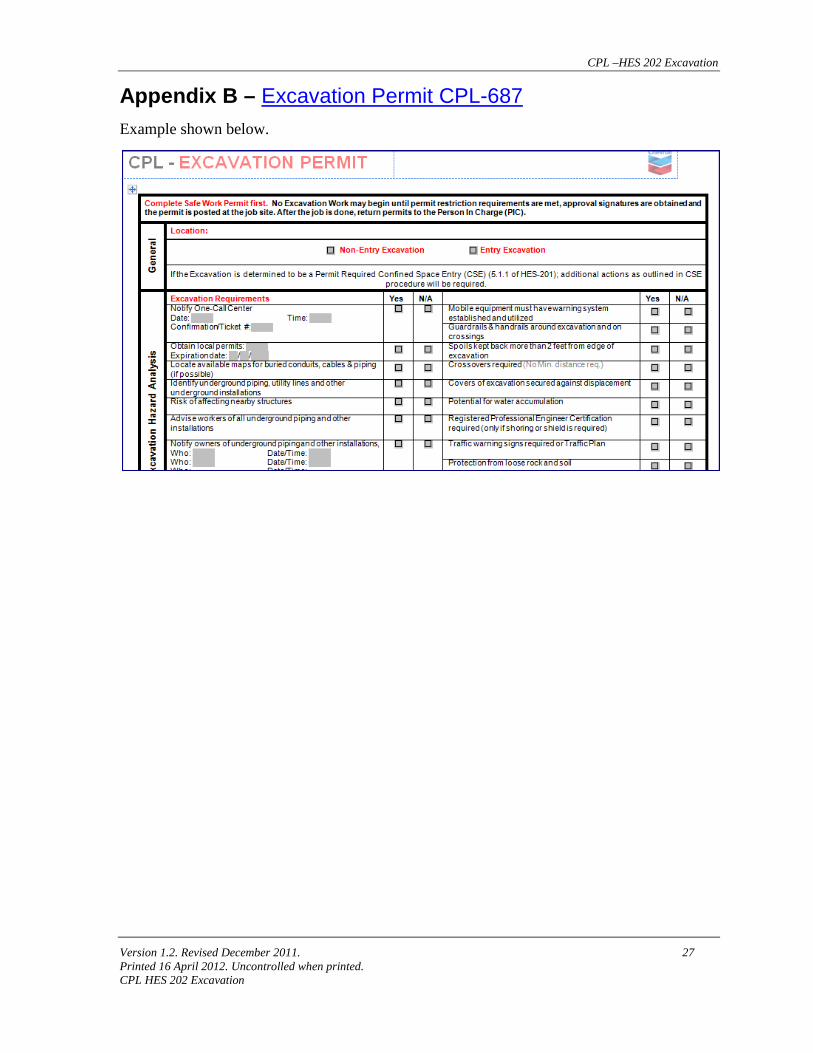
8.1 Required Documents • An "Excavation Permit" — CPL-687 is used to document this procedure.
• A California Annual Excavation Permit is required to conduct excavations in California.
• A California Activity Notification Form is used to inform CAL OSHA of excavation activities.
8.2 Document Storage and Retention Time • The Excavation Permit will be retained for two (2) years after the job is complete in
the appropriate office.
• California Annual Excavation Permit will be posted in the appropriate office.
CPL –HES 202 Excavation
Version 1.2. Revised December 2011. 23 Printed 16 April 2012. Uncontrolled when printed. CPL HES 202 Excavation
Appendix A – Glossary
Bell-bottom Pier Hole This is a type of shaft or footing excavation which has a bottom cross section wider than the top cross section, thereby, forming a belled shape.
Benching Terracing or stepping the sides of an excavation to prevent a cave-in. Benching is a method of protecting employees from cave-ins by excavating the sides of an excavation to form one or a series of horizontal levels or steps, usually with vertical or near-vertical surfaces between levels.
Cave-in The separation of a mass of soil or rock material from the side of an excavation, or the loss of soil from under a trench shield or support system, and its sudden movement into the excavation, either by falling or sliding, in sufficient quantity so that it could entrap, bury, or otherwise injure and immobilize a person.
Competent Person A person trained in and knowledgeable about soil analysis, the use of protective systems, and the requirements of the OSHA Construction Standard 29 CFR 1926.650. A Competent Person must be capable of identifying existing and predictable hazards in excavation work and have the authority to take prompt measures to abate these hazards. In California, the Competent Person must know CAL OSHA Standards.
Contractor A person who agrees to furnish materials or perform services at a specified price for construction. The person performing the work.
Cross Braces The horizontal members of a shoring system installed perpendicular to the sides of the excavation, the ends of which bear against either uprights or wales.
Egress A continuous and unobstructed way of exit travel from any point in an excavation to a safe location outside the excavation.
CPL –HES 202 Excavation
Version 1.2. Revised December 2011. 24 Printed 16 April 2012. Uncontrolled when printed. CPL HES 202 Excavation
Excavation Any man-made cut, cavity, trench, or depression in the earth's surface, formed by earth removal. By definition, excavations include trenches.
Gas Testing The use of portable gas testing instruments to determine levels of flammable and toxic vapors or gases present in the atmosphere.
Hazardous Atmosphere An atmosphere which, by reason of being explosive, flammable, poisonous, corrosive, oxidizing, irritating, oxygen deficient, toxic, or otherwise harmful, may cause death, illness, or injury.
Person Conducting the Work The person(s) conducting the excavation or working in or around the excavation. This includes all personnel company and contractor.
Person-In-Charge The Team Leader responsible for the assets, or their designated CPL employee representative, or a qualified third party contractor, that has overall responsibility for determining acceptable excavation conditions in the area are safe for the excavation work to be performed and for the safety of personnel and equipment until the job is complete.
The PIC can be a (Qualified Third Party) inspector who is acting as the company representative.
Protective System A method of protecting employees from cave-ins, materials falling or rolling from an excavation face or into an excavation or from the collapse of adjacent structures. Protective systems include, but are not limited to, support systems, benching systems, sloping systems, and shield systems.
Qualified Gas Tester Personnel (company and contractor) who have been trained in the use of portable gas testing instruments and have demonstrated their use in the field. Only qualified gas testers may conduct gas tests.
Qualified Third Party Contractors A Contractor separate and distinct from the contractor performing the work, who has been trained in CPL applicable procedures, and understands the hazards, risks, exposures, and associated impact to operations from the activities.
CPL –HES 202 Excavation
Version 1.2. Revised December 2011. 25 Printed 16 April 2012. Uncontrolled when printed. CPL HES 202 Excavation
Requestor/Work Owner The person who selects, hires, or oversees the work of a contractor.
Shield A structure that is able to withstand the forces imposed on it by a cave-in and thereby protects employees within the structure. Shields can be permanent structures or can be designed to be portable and moved along as work progresses. Shields can be either pre-manufactured or job-built in accordance with the requirements found in this procedure. Shields used in trenches are usually referred to as trench boxes or trench shields. This is also referred to as shield system.
Shoring A structure that supports the sides of an excavation and is designed to prevent cave-ins. The structure can be made of metal, wood, or be hydraulic. This is also referred to as a shoring system.
Sloping A method of protecting employees from cave-ins by excavating to form sides of an excavation that is inclined away from the excavation so as to prevent cave-ins. The acceptable angle of the incline required to prevent a cave-in is dependant of such factors as the soil type, environmental conditions of exposure, and application of surcharge loads. This is also referred to as a sloping system.
Support System A structure, such as an underpinning, bracing or shoring which provides support to an adjacent structure, underground installation or the sides of an excavation.
Tabulated Data Tables and charts approved by a Registered Professional Engineer to design and construct a protective system.
Trench A narrow excavation (in relation to its length) made below the surface of the ground. In general, the depth is greater than the width, but the width of a trench (measured at the bottom) is not greater than 15 feet (4.6 meters). If forms or other structures are installed or constructed in an excavation so as to reduce the dimension measured from the forms or structure to the side of the excavation to 15 feet (4.6 meters) or less (measured at the bottom of the excavation), the excavation is also considered to be a trench. This is also called a trench excavation.
CPL –HES 202 Excavation
Version 1.2. Revised December 2011. 26 Printed 16 April 2012. Uncontrolled when printed. CPL HES 202 Excavation
Underground Installations Buried utility and production installations such as sewer, telephone, fuel, electric, water lines, or any other underground installations that may be expected to be encountered during excavation work.
CPL –HES 202 Excavation
Version 1.2. Revised December 2011. 27 Printed 16 April 2012. Uncontrolled when printed. CPL HES 202 Excavation
Appendix B – Excavation Permit CPL-687 Example shown below.
CPL –HES 202 Excavation
Version 1.2. Revised December 2011. C-1 Printed 16 April 2012. Uncontrolled when printed. CPL HES 202 Excavation
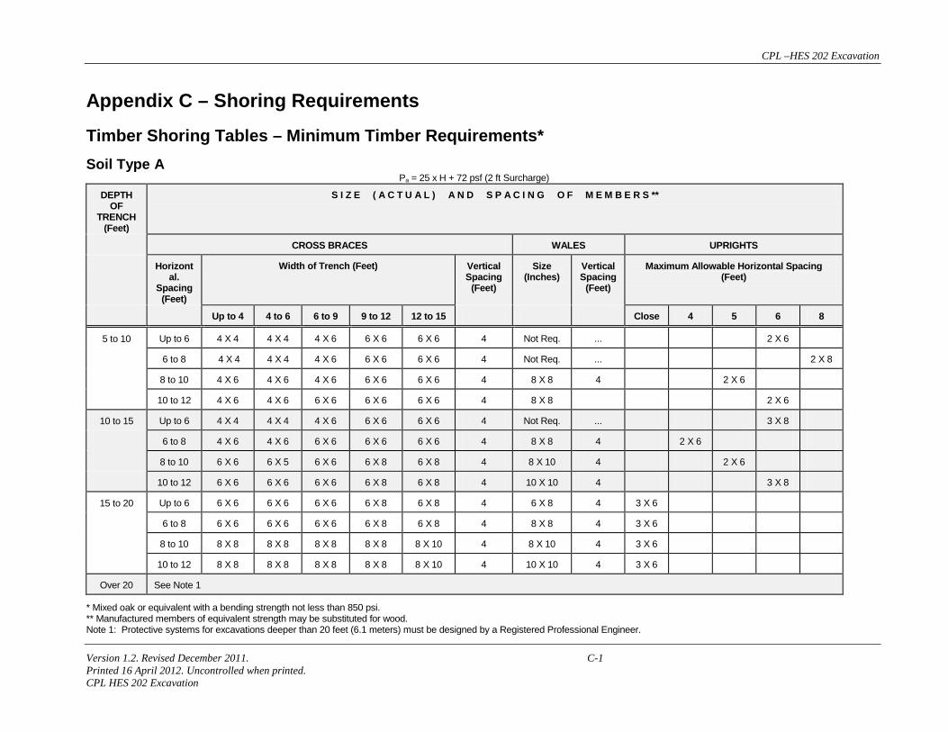
Appendix C – Shoring Requirements
Timber Shoring Tables – Minimum Timber Requirements* Soil Type A Pa = 25 x H + 72 psf (2 ft Surcharge)
DEPTH OF
TRENCH (Feet)
S I Z E ( A C T U A L ) A N D S P A C I N G O F M E M B E R S **
CROSS BRACES WALES UPRIGHTS
Horizontal.
Spacing (Feet)
Width of Trench (Feet) Vertical Spacing
(Feet)
Size (Inches)
Vertical Spacing
(Feet)
Maximum Allowable Horizontal Spacing (Feet)
Up to 4 4 to 6 6 to 9 9 to 12 12 to 15 Close 4 5 6 8
5 to 10 Up to 6 4 X 4 4 X 4 4 X 6 6 X 6 6 X 6 4 Not Req. ... 2 X 6
6 to 8 4 X 4 4 X 4 4 X 6 6 X 6 6 X 6 4 Not Req. ... 2 X 8
8 to 10 4 X 6 4 X 6 4 X 6 6 X 6 6 X 6 4 8 X 8 4 2 X 6
10 to 12 4 X 6 4 X 6 6 X 6 6 X 6 6 X 6 4 8 X 8 2 X 6
10 to 15 Up to 6 4 X 4 4 X 4 4 X 6 6 X 6 6 X 6 4 Not Req. ... 3 X 8
6 to 8 4 X 6 4 X 6 6 X 6 6 X 6 6 X 6 4 8 X 8 4 2 X 6
8 to 10 6 X 6 6 X 5 6 X 6 6 X 8 6 X 8 4 8 X 10 4 2 X 6
10 to 12 6 X 6 6 X 6 6 X 6 6 X 8 6 X 8 4 10 X 10 4 3 X 8
15 to 20 Up to 6 6 X 6 6 X 6 6 X 6 6 X 8 6 X 8 4 6 X 8 4 3 X 6
6 to 8 6 X 6 6 X 6 6 X 6 6 X 8 6 X 8 4 8 X 8 4 3 X 6
8 to 10 8 X 8 8 X 8 8 X 8 8 X 8 8 X 10 4 8 X 10 4 3 X 6
10 to 12 8 X 8 8 X 8 8 X 8 8 X 8 8 X 10 4 10 X 10 4 3 X 6
Over 20 See Note 1
* Mixed oak or equivalent with a bending strength not less than 850 psi. ** Manufactured members of equivalent strength may be substituted for wood. Note 1: Protective systems for excavations deeper than 20 feet (6.1 meters) must be designed by a Registered Professional Engineer.
CPL –HES 202 Excavation
Version 1.2. Revised December 2011. C-2 Printed 16 April 2012. Uncontrolled when printed. CPL HES 202 Excavation
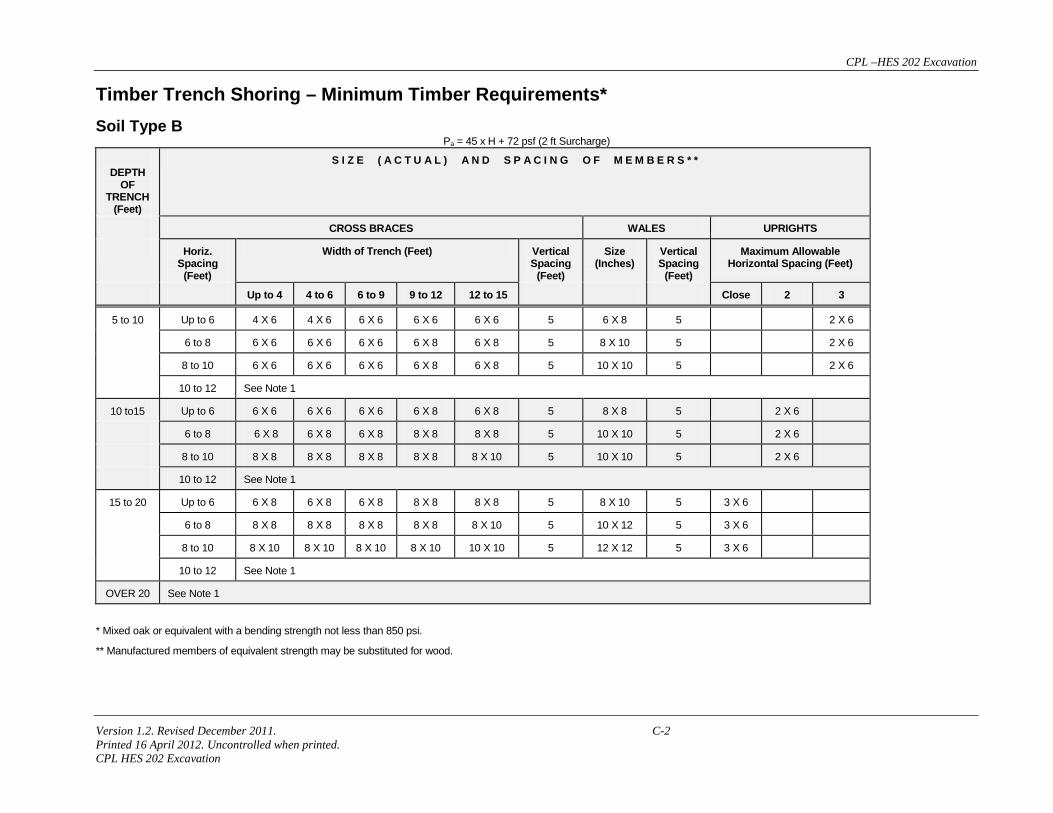
Timber Trench Shoring – Minimum Timber Requirements* Soil Type B Pa = 45 x H + 72 psf (2 ft Surcharge)
DEPTH
OF TRENCH
(Feet)
S I Z E ( A C T U A L ) A N D S P A C I N G O F M E M B E R S * *
CROSS BRACES WALES UPRIGHTS
Horiz. Spacing
(Feet)
Width of Trench (Feet) Vertical Spacing
(Feet)
Size (Inches)
Vertical Spacing
(Feet)
Maximum Allowable Horizontal Spacing (Feet)
Up to 4 4 to 6 6 to 9 9 to 12 12 to 15 Close 2 3
5 to 10 Up to 6 4 X 6 4 X 6 6 X 6 6 X 6 6 X 6 5 6 X 8 5 2 X 6
6 to 8 6 X 6 6 X 6 6 X 6 6 X 8 6 X 8 5 8 X 10 5 2 X 6
8 to 10 6 X 6 6 X 6 6 X 6 6 X 8 6 X 8 5 10 X 10 5 2 X 6
10 to 12 See Note 1
10 to15 Up to 6 6 X 6 6 X 6 6 X 6 6 X 8 6 X 8 5 8 X 8 5 2 X 6
6 to 8 6 X 8 6 X 8 6 X 8 8 X 8 8 X 8 5 10 X 10 5 2 X 6
8 to 10 8 X 8 8 X 8 8 X 8 8 X 8 8 X 10 5 10 X 10 5 2 X 6
10 to 12 See Note 1
15 to 20 Up to 6 6 X 8 6 X 8 6 X 8 8 X 8 8 X 8 5 8 X 10 5 3 X 6
6 to 8 8 X 8 8 X 8 8 X 8 8 X 8 8 X 10 5 10 X 12 5 3 X 6
8 to 10 8 X 10 8 X 10 8 X 10 8 X 10 10 X 10 5 12 X 12 5 3 X 6
10 to 12 See Note 1
OVER 20 See Note 1
* Mixed oak or equivalent with a bending strength not less than 850 psi.
** Manufactured members of equivalent strength may be substituted for wood.
CPL –HES 202 Excavation
Version 1.2. Revised December 2011. C-3 Printed 16 April 2012. Uncontrolled when printed. CPL HES 202 Excavation
Timber Trench Shoring – Minimum Timber Requirements* Soil Type C Pa = 80 x H + 72 psf (2 ft Surcharge)
DEPTH OF
TRENCH (Feet)
S I Z E ( A C T U A L ) A N D S P A C I N G O F M E M B E R S * *
CROSS BRACES WALES UPRIGHTS
Horiz. Spacing
(Feet)
Width of Trench (Feet) Vertical Spacing
(Feet)
Size (Inches)
Vertical Spacing
(Feet)
Maximum Allowable Horizontal Spacing (Feet) (See Note 2)
Up to 4 4 to 6 6 to 9 9 to 12 12 to 15 Close
5 to 10
Up to 6 6 X 8 6 X 8 6 X 8 8 X 8 8 X 8 5 8 X 10 5 2 X 6
6 to 8 8 X 8 8 x 8 8 X 8 8 X 8 8 X 10 5 10 x 12 5 2 X 6
8 to 10 8 x 10 8 x 10 8 x 10 8 x 10 10 x 10 5 12 x 12 5 2 X 6
10 to 12 See Note 1
10 to 15
Up to 6 8 X 8 8 X 8 8 X 8 8 X 8 8 X 10 5 10 X 12 5 2 X 6
6 to 8 8 X 10 8 X 10 8 X 10 8 X 10 10 X 10 5 12 X 12 5 2 X 6
8 to 10 See Note 1
10 to 12 See Note 1
15 to 20
Up to 6 8 x 10 8 x 10 8 x 10 8 x 10 10 x 10 5 12 x 12 5 3 X 6
6 to 8 See Note 1
8 to 10 See Note 1
10 to 12 See Note 1
OVER 20 See Note 1 * Mixed oak or equivalent with a bending strength not less than 850 psi.
*Manufactured members of equivalent strength may be substituted for wood.
CPL –HES 202 Excavation
Version 1.2. Revised December 2011. C-4 Printed 16 April 2012. Uncontrolled when printed. CPL HES 202 Excavation
Timber Trench Shoring – Minimum Timber Requirements * Soil Type A Pa = 25 x H + 72 psf (2 ft. Surcharge)
DEPTH OF
TRENCH (Feet)
S I Z E ( S 4 S ) A N D S P A C I N G O F M E M B E R S * *
CROSS BRACES WALES UPRIGHTS
Horiz. Spacing
(Feet)
Width of Trench (Feet) Vertical Spacing
(Feet)
Size (Inches)
Vertical Spacing
(Feet)
Maximum Allowable Horizontal Spacing (Feet)
Up to 4 4 to 6 6 to 9 9 to 12 12 to 15 Close 4 5 6 8
5 to 10
Up to 6 4 X 4 4 X 4 4 X 4 4 X 4 4 X 6 4 Not Req. Not Req. 4 X 6
6 to 8 4 X 4 4 X 4 4 X 4 4 X 6 4 X 6 4 Not Req. Not Req. 4 X 8
8 to 10 4 X 6 4 X 6 4 X 6 6 X 6 6 X 6 4 8 X 8 4 4 X 6
10 to 12 4 X 6 4 X 6 4 X 6 6 X 6 6 X 6 4 8 X 8 4 4 X 6
10 to 15
Up to 6 4 X 4 4 X 4 4 X 4 6 X 6 6 X 6 4 Not Req. Not Req. 4 X 10
6 to 8 4 X 6 4 X 6 4 X 6 6 X 6 6 X 6 4 6 X 8 4 4 X 6
8 to 10 6 X 6 6 X 6 6 X 6 6 X 6 6 X 6 4 8 X 8 4 4 X 8
10 to 12 6 X 6 6 X 6 6 X 6 6 X 6 6 X 6 4 8 X 10 4 4 X 6 4 X 10
15 to 20
Up to 6 6 X 6 6 X 6 6 X 6 6 X 6 6 X 6 4 6 X 8 4 3 X 6
6 to 8 6 X 6 6 X 6 6 X 6 6 X 6 6 X 6 4 8 X 8 4 3 X 6 4 X 12
8 to 10 6 X 6 6 X 6 6 X 6 6 X 6 6 X 8 4 8 X 10 4 3 X 6
10 to 12 6 X 6 6 X 6 6 X 6 6 X 8 6 X 8 4 8 X 10 4 3 X 6 4 X 12
OVER 20 See Note 1
* Douglas fir or equivalent with a bending strength not less than 1500 psi.
** Manufactured members of equivalent strength may be substituted for wood.
CPL –HES 202 Excavation
Version 1.2. Revised December 2011. C-5 Printed 16 April 2012. Uncontrolled when printed. CPL HES 202 Excavation
Timber Trench Shoring – Minimum Timber Requirements* Soil Type B Pa = 45 x H + 72 psf (2 ft. Surcharge)
DEPTH OF
TRENCH (Feet)
S I Z E ( S 4 S ) A N D S P A C I N G O F M E M B E R S * *
CROSS BRACES WALES UPRIGHTS
Horiz. Spacing
(Feet)
Width of Trench (Feet) Vertical Spacing
(Feet)
Size (Inches)
Vertical Spacing
(Feet)
Maximum Allowable Horizontal Spacing (Feet)
Up to 4 4 to 6 6 to 9 9 to 12 12 to 15 Close 2 3 4 6
5 to 10
Up to 6 4 X 6 4 X 6 4 X 6 6 X 6 6 X 6 5 6 X 8 5 3 X 12 4 X 8
4 X 12
6 to 8 4 X 6 4 X 6 6 X 6 6 X 6 6 X 6 5 8 X 8 5 3 X 8 4 X 8
8 to 10 4 X 6 4 X 6 6 X 6 6 X 6 6 X 8 5 8 X 10 5 4 X 8
10 to 12 See Note 1
10 to 15 Up to 6 6 X 6 6 X 6 6 X 6 6 X 8 6 X 8 5 8 X 8 5 3 X 6 4 X 10
6 to 8 6 X 8 6 X 8 6 X 8 8 X 8 8 X 8 5 10 X 10 5 3 X 6 4 X 10
8 to 10 6 X 8 6 X 8 8 X 8 8 X 8 8 X 8 5 10 X 12 5 3 X 6 4 X 10
10 to 12 See Note 1
15 to 20 Up to 6 6 X 8 6 X 8 6 X 8 6 X 8 8 X 8 5 8 X 10 5 4 X 6
6 to 8 6 X 8 6 X 8 6 X 8 8 X 8 8 X 8 5 10 X 12 5 4 X 6
8 to 10 8 X 8 8 X 8 8 X 8 8 X 8 8 X 8 5 12 X 12 5 4 X 6
10 to 12 See Note 1
OVER 20 See Note 1
* Douglas fir or equivalent with a bending strength not less than 1500 psi. ** Manufactured members of equivalent strength may be substituted for wood.
CPL –HES 202 Excavation
Version 1.2. Revised December 2011. C-6 Printed 16 April 2012. Uncontrolled when printed. CPL HES 202 Excavation
Timber Trench Shoring – Minimum Timber Requirements* Soil Type C Pa = 80 x H + 72 psf (2 ft. Surcharge)
DEPTH OF TRENCH
(Feet)
S I Z E ( S 4 S ) A N D S P A C I N G O F M E M B E R S * *
CROSS BRACES WALES UPRIGHTS
Horiz. Spacing
(Feet)
Width of Trench (Feet) Vertical Spacing (Feet)
Size (Inches)
Vertical Spacing
(Feet)
Maximum Allowable Horizontal Spacing (Feet) (See Note 2)
Up to 4 4 to 6 6 to 9 9 to 12 12 to 15 Close
5 to 10 Up to 6 6 X 6 6 X 6 6 X 6 6 X 6 8 X 8 5 8 X 8 5 3 X 6
6 to 8 6 X 6 6 x 6 6 X 6 8 X 8 8 X 8 5 10 x 10 5 3 X 6
8 to 10 6 X 6 6 X 6 8 x 8 8 x 8 8 x 8 5 10 x 12 5 3 X 6
10 to 12 See Note 1
10 to 15 Up to 6 6 X 8 6 X 8 6 X 8 8 X 8 8 X 8 5 10 X 10 5 4 X 6
6 to 8 8 X 8 8 X 8 8 X 8 8 X 8 8 X 8 5 12 X 12 5 4 X 6
8 to 10 See Note 1
10 to 12 See Note 1
15 to 20 Up to 6 8 x 8 8 x 8 8 x 8 8 x 10 8 x 10 5 10 x 12 5 4 X 6
6 to 8 See Note 1
8 to 10 See Note 1
10 to 12 See Note 1
OVER 20 See Note 1
* Douglas fir or equivalent with a bending strength not less than 1500 psi.
** Manufactured members of equivalent strength may be substituted for wood.
CPL –HES 202 Excavation
Version 1.2. Revised December 2011. C-7 Printed 16 April 2012. Uncontrolled when printed. CPL HES 202 Excavation
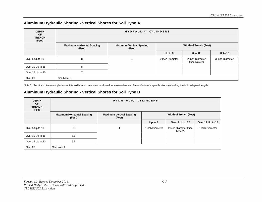
Aluminum Hydraulic Shoring - Vertical Shores for Soil Type A
DEPTH OF
TRENCH (Feet)
H Y D R A U L I C CY L I N D E R S
Maximum Horizontal Spacing (Feet)
Maximum Vertical Spacing (Feet)
Width of Trench (Feet)
Up to 8 8 to 12 12 to 15
Over 5 Up to 10 8 4 2 Inch Diameter 2 Inch Diameter (See Note 2)
3 Inch Diameter
Over 10 Up to 15 8
Over 15 Up to 20 7
Over 20 See Note 1 Note 1: Two-inch diameter cylinders at this width must have structural steel tube over-sleeves of manufacturer's specifications extending the full, collapsed length.
Aluminum Hydraulic Shoring - Vertical Shores for Soil Type B
DEPTH OF
TRENCH (Feet)
H Y D R A U L I C CY L I N D E R S
Maximum Horizontal Spacing (Feet)
Maximum Vertical Spacing (Feet)
Width of Trench (Feet)
Up to 8 Over 8 Up to 12 Over 12 Up to 15
Over 5 Up to 10 8 4 2 Inch Diameter 2 Inch Diameter (See Note 2)
3 Inch Diameter
Over 10 Up to 15 6.5
Over 15 Up to 20 5.5
Over 20 See Note 1
CPL –HES 202 Excavation
Version 1.2. Revised December 2011. C-8 Printed 16 April 2012. Uncontrolled when printed. CPL HES 202 Excavation
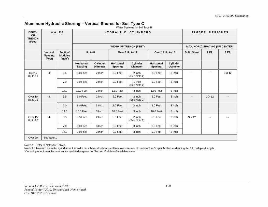
Aluminum Hydraulic Shoring – Vertical Shores for Soil Type C Water Systems for Soil Type B
DEPTH OF
TRENCH (Feet)
W A L E S H Y D R A U L I C C Y L I N D E R S T I M B E R U P R I G H T S
WIDTH OF TRENCH (FEET) MAX. HORIZ. SPACING (ON CENTER)
Vertical Spacing
(Feet)
Section* Modules (Inch3)
Up to 8 Over 8 Up to 12 Over 12 Up to 15 Solid Sheet 2 FT. 3 FT.
Horizontal Spacing
Cylinder Diameter
Horizontal Spacing
Cylinder Diameter
Horizontal Spacing
Cylinder Diameter
Over 5 Up to 10
4 3.5 8.0 Feet 2 Inch 8.0 Feet 2 Inch (See Note 2)
8.0 Feet 3 Inch --- --- 3 X 12
7.0 9.0 Feet 2 Inch 9.0 Feet 2 Inch (See Note 2)
9.0 Feet 3 Inch
14.0 12.0 Feet 3 Inch 12.0 Feet 3 Inch 12.0 Feet 3 Inch
Over 10 Up to 15
4 3.5 6.0 Feet 2 Inch 6.0 Feet 2 Inch (See Note 2)
6.0 Feet 3 Inch --- 3 X 12 ---
7.0 8.0 Feet 3 Inch 8.0 Feet 3 Inch 8.0 Feet 3 Inch
14.0 10.0 Feet 3 Inch 10.0 Feet 3 Inch 10.0 Feet 8 Inch
Over 15 Up to 20
4 3.5 5.5 Feet 2 Inch 5.5 Feet 2 Inch (See Note 2)
5.5 Feet 3 Inch 3 X 12 --- ---
7.0 6.0 Feet 3 Inch 6.0 Feet 3 Inch 6.0 Feet 3 Inch
14.0 9.0 Feet 3 Inch 9.0 Feet 3 Inch 9.0 Feet 3 Inch
Over 20 See Note 1 Notes 1: Refer to Notes for Tables. Notes 2: Two-inch diameter cylinders at this width must have structural steel tube over-sleeves of manufacturer's specifications extending the full, collapsed length. *Consult product manufacturer and/or qualified engineer for Section Modules of available wales.
CPL –HES 202 Excavation
Version 1.2. Revised December 2011. C-9 Printed 16 April 2012. Uncontrolled when printed. CPL HES 202 Excavation
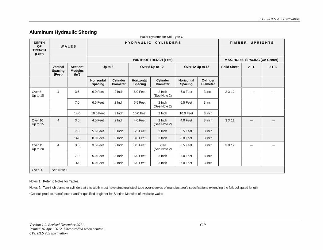
Aluminum Hydraulic Shoring Waler Systems for Soil Type C
DEPTH OF
TRENCH (Feet)
W A L E S
H Y D R A U L I C C Y L I N D E R S T I M B E R U P R I G H T S
WIDTH OF TRENCH (Feet) MAX. HORIZ. SPACING (On Center)
Vertical Spacing
(Feet)
Section* Modules
(In3)
Up to 8 Over 8 Up to 12 Over 12 Up to 15 Solid Sheet 2 FT. 3 FT.
Horizontal Spacing
Cylinder Diameter
Horizontal Spacing
Cylinder Diameter
Horizontal Spacing
Cylinder Diameter
Over 5 Up to 10
4 3.5 6.0 Feet 2 Inch 6.0 Feet 2 Inch (See Note 2)
6.0 Feet 3 Inch 3 X 12 --- ---
7.0 6.5 Feet 2 Inch 6.5 Feet 2 Inch (See Note 2)
6.5 Feet 3 Inch
14.0 10.0 Feet 3 Inch 10.0 Feet 3 Inch 10.0 Feet 3 Inch
Over 10 Up to 15
4 3.5 4.0 Feet 2 Inch 4.0 Feet 2 Inch (See Note 2)
4.0 Feet 3 Inch 3 X 12 --- ---
7.0 5.5 Feet 3 Inch 5.5 Feet 3 Inch 5.5 Feet 3 Inch
14.0 8.0 Feet 3 Inch 8.0 Feet 3 Inch 8.0 Feet 8 Inch
Over 15 Up to 20
4 3.5 3.5 Feet 2 Inch 3.5 Feet 2 IN (See Note 2)
3.5 Feet 3 Inch 3 X 12 --- ---
7.0 5.0 Feet 3 Inch 5.0 Feet 3 Inch 5.0 Feet 3 Inch
14.0 6.0 Feet 3 Inch 6.0 Feet 3 Inch 6.0 Feet 3 Inch
Over 20 See Note 1
Notes 1: Refer to Notes for Tables.
Notes 2: Two-inch diameter cylinders at this width must have structural steel tube over-sleeves of manufacturer's specifications extending the full, collapsed length.
*Consult product manufacturer and/or qualified engineer for Section Modules of available wales
CPL –HES 202 Excavation
Version 1.2. Revised December 2011 D-1 Printed 16 April 2012. Uncontrolled when printed. CPL HES 202 Excavation
Appendix D – To Identifying the Location of Underground Utilities Prior to Excavating Call the 811 or Regional One-Call Center 48 hours in advance before digging is scheduled to begin. Wait 48 hours for the site to be marked (unless it is an emergency line repair), and observe the marks and dig with care. If at all possible have the utility owners on site while the excavation is taking place.
Plan your work. For larger projects, call in only the work that can be accomplished within a ten-day period.
Have the following information available prior to calling the One-Call Center:
Name and telephone number of the excavator and name and telephone number of the company
Date and time the work is scheduled to begin
Specific location address or description of the work site
Nearest intersecting roadway to the work site
Distance and direction of the work site from the nearest intersection
Advise the one-call operator if explosives will be used
“X” and “Y” or Lat/Long Coordinates of dig site, if available
Record the locate request ticket number provided by the one-call operator. It is your proof of the call and may be requested by an enforcement agency.
If digging activity comes within 24 inches of a utility line or pipeline, exercise extreme caution. Hand digging is required to expose the buried line.
Markings for underground utilities are considered valid as long as they are visible up to ten calendar days from the “mark-by” time. The “mark-by” time is provided by the one-call operator but will not holidays and weekends. For larger projects, call in only the work that can be accomplished within a ten-day period.
If damage to an underground utility occurs, notify the utility operator or the pipeline company directly.
If there is an emergency situation, (i.e., danger to life, health, or property requiring immediate attention), take steps to safeguard health and property.
Wherever possible, use white paint, stakes, or flags to mark the proposed excavation area.
Remember, not all utilities are members of 811 or the Regional One-Call Center. You should call non-member utility operators directly if there is evidence that other utilities are in the vicinity and they are not on the list of utilities identified by the Regional One-Call Center.