excellence in environmental stewardship e-toolkit (ees) version-01
TRANSCRIPT

Excellence in Environmental Stewardship e-toolkit (EES) Version-01
An Initiative of the Prospectors & Developers Association of Canada
March 2nd, 2009

I
TABLE OF CONTENTS
1.0 Welcome to the Environmental Stewardship Toolkit ................................ 1
2.0 The Excellence in Environmental Stewardship e-toolkit Good Practice Guidelines ...................................................................................... 3
2.1 Introduction ............................................................................................................. 4 2.1.1 History ............................................................................................................................. 4 2.1.2 Purpose ........................................................................................................................... 5 2.1.3 Layout of EES Web Site .................................................................................................. 5 2.1.4 Scope .............................................................................................................................. 7 2.1.5 Compilation and Editing .................................................................................................. 8 2.1.6 Intended Audience .......................................................................................................... 9 2.1.7 The Future ..................................................................................................................... 10
2.2 Management Essentials ........................................................................................ 10 2.2.1 Exploration Code of Conduct ........................................................................................ 11 2.2.2 Environmental Challenges ............................................................................................ 12 2.2.3 Legislation and Permitting ............................................................................................. 12 2.2.4 Planning ........................................................................................................................ 13 2.2.5 Due Diligence ................................................................................................................ 15
2.2.5.1 Wilderness Sites ..................................................................................................... 16 2.2.5.2 Previously Explored Sites ....................................................................................... 16 2.2.5.3 Previous Production Sites ...................................................................................... 17
2.2.6 Contractor Selection and Management......................................................................... 17 2.2.7 Reviews and Audits ....................................................................................................... 18 2.2.8 Record Keeping ............................................................................................................. 19 2.2.9 Reporting ....................................................................................................................... 19
3.0 Archaeological and Cultural Sites ............................................................ 21
4.0 Planning Needs .......................................................................................... 23
4.1 Basic Elements ...................................................................................................... 23 4.1.1 Exploration Code of Conduct ........................................................................................ 23 4.1.2 Planning ........................................................................................................................ 24 4.1.3 Due Diligence ................................................................................................................ 24 4.1.4 Legislation and Permitting ............................................................................................. 25
4.2 Operational Aspects.............................................................................................. 25 4.2.1 Community Relations .................................................................................................... 26 4.2.2 Contractor Selection and Management......................................................................... 26 4.2.3 Health and Safety .......................................................................................................... 26 4.2.4 Wildlife ........................................................................................................................... 27
4.3 Policies and Reporting .......................................................................................... 27 4.3.1 Fire Prevention, Policy, and Response ......................................................................... 27 4.3.2 Training ......................................................................................................................... 28 4.3.3 Reviews and Audits ....................................................................................................... 28 4.3.4 Record Keeping ............................................................................................................. 28 4.3.5 Reporting ....................................................................................................................... 28
5.0 Land Disturbance ........................................................................................ 29
5.1 Causes of Erosion ................................................................................................. 29
5.2 Consequences of Erosion .................................................................................... 31

II
5.3 Methods of Erosion Control ................................................................................. 31
5.4 Minimizing Disturbances ...................................................................................... 32 5.4.1 Clearing of Vegetation ................................................................................................... 33 5.4.2 Soil Conservation .......................................................................................................... 34
5.4.2.1 Trenches and Pits ................................................................................................... 35 5.4.2.2 Managing Soil on Slopes ........................................................................................ 37 5.4.2.3 Soil Stabilization ..................................................................................................... 38
5.4.3 Vehicle and Equipment Use .......................................................................................... 39
5.5 Managing Drainage and Runoff ............................................................................ 40 5.5.1 Road and Track Design................................................................................................. 40
5.5.1.1 Planning .................................................................................................................. 41 5.5.1.2 Location .................................................................................................................. 42 5.5.1.3 Construction ............................................................................................................ 44 5.5.1.4 Drainage ................................................................................................................. 45 5.5.1.5 Creek Crossings ..................................................................................................... 47 5.5.1.6 Track Use ............................................................................................................... 48
5.5.2 Ditches and Drains ........................................................................................................ 48 5.5.3 Bridges and Crossings .................................................................................................. 49
5.5.3.1 Vegetation Management ........................................................................................ 49 5.5.3.2 Types of Crossings ................................................................................................. 50
5.6 Controlling Sediment ............................................................................................ 63 5.6.1 Straw Bales and Sandbags ........................................................................................... 64 5.6.2 Silt Fences ..................................................................................................................... 65 5.6.3 Brush Barriers ............................................................................................................... 66 5.6.4 Diversions and Dams .................................................................................................... 67 5.6.5 Sediment Traps or Basins ............................................................................................. 69
5.7 Special Terrains ..................................................................................................... 70 5.7.1 Arctic and Alpine Terrains ............................................................................................. 70 5.7.2 Arid and Tropical Terrains ............................................................................................. 76 5.7.3 Riparian Areas ............................................................................................................... 93 5.7.4 Wetlands ....................................................................................................................... 94 5.7.5 Beaches and Coastal Sand Dunes ............................................................................... 95
6.0 Site Management ........................................................................................ 97
6.1 Health and Safety .................................................................................................. 97 6.1.1 Health and Safety Management Systems ..................................................................... 98
6.2 Housekeeping ........................................................................................................ 98 6.2.1 Housekeeping and Hazardous Materials ...................................................................... 99
6.3 Monitoring and Inspections ................................................................................ 100
6.4 Site Clearing ........................................................................................................ 101
6.5 Drainage Control ................................................................................................. 101 6.5.1 Run-on ......................................................................................................................... 101 6.5.2 Runoff .......................................................................................................................... 102
6.6 Maintenance ........................................................................................................ 103
6.7 Security ................................................................................................................ 103 6.7.1 Induction and Orientations .......................................................................................... 104 6.7.2 Log Book and Emergency Response .......................................................................... 105 6.7.3 Theft and Vandalism ................................................................................................... 105
6.8 Baseline Studies .................................................................................................. 106

III
6.8.1 Water Resources ......................................................................................................... 106 6.8.2 Cultural and Archaeological Resources ...................................................................... 107 6.8.3 Exemplary Natural Resources .................................................................................... 107
6.9 Sample Handling ................................................................................................. 108 6.9.1 Collection ..................................................................................................................... 108 6.9.2 Handling ...................................................................................................................... 110 6.9.3 Transport ..................................................................................................................... 111 6.9.4 Drilling Sample Handling ............................................................................................. 112
6.10 Concurrent Reclamation ................................................................................... 112
6.11 Further Considerations ..................................................................................... 114
7.0 Air Management ........................................................................................ 116
7.1 Sensitivities and Concerns ................................................................................. 116
7.2 Planning ............................................................................................................... 116
7.3 Work Practices .................................................................................................... 116
8.0 Fish and Wildlife Management................................................................. 118
8.1 Sensitivities and Concerns ................................................................................. 118
8.2 Impacts ................................................................................................................ 118
8.3 Planning ............................................................................................................... 119
8.4 Work Practices .................................................................................................... 119 8.4.1 Vermin Control ............................................................................................................ 120
8.5 Dangerous Wildlife .............................................................................................. 121 8.5.1 Bear Attacks ................................................................................................................ 122 8.5.2 Playing Dead ............................................................................................................... 123 8.5.3 Fighting Back ............................................................................................................... 123 8.5.4 Using Bear Spray ........................................................................................................ 123
9.0 Water Use and Conservation ................................................................... 124
9.1 Sensitivities and Concerns ................................................................................. 124
9.2 Planning ............................................................................................................... 124
9.3 Water Control ...................................................................................................... 124
9.4 Potable Water: Location, Supply, and Storage ................................................. 125
9.5 Non-Potable Water: Location, Design, and Extraction ..................................... 126
9.6 Water Discharge .................................................................................................. 127
9.7 Artesian Water ..................................................................................................... 127
9.8 Conservation ....................................................................................................... 127
9.9 Protection ............................................................................................................ 128
10.0 Hazardous Material ................................................................................. 129
10.1 Fuels and Petroleum Products ......................................................................... 130 10.1.1 Storage Site Setup .................................................................................................... 131 10.1.2 Use of Drums and Other Containers ......................................................................... 133 10.1.3 Refuelling Operations ................................................................................................ 134

IV
10.1.4 Transporting Fuel and Petroleum Products .............................................................. 135 10.1.5 Handling Fuels and Oils on Water ............................................................................ 135
10.2 Propane and Other Liquefied Petroleum Gases .............................................. 136
10.3 Explosives ......................................................................................................... 136 10.3.1 Transport and Storage of Explosives ........................................................................ 137 10.3.2 Handling of Fuses and Blasting Caps ....................................................................... 139 10.3.3 Blasting ...................................................................................................................... 140
10.4 Solvents and Paints .......................................................................................... 141
10.5 Drilling Fluids .................................................................................................... 142 10.5.1 Handling and Storage of Drilling Fluids ..................................................................... 143
10.6 Pesticides and Herbicides ................................................................................ 144 10.6.1 Handling and Storage of Pesticides and Herbicides ................................................. 144
10.7 Acids and Bases ................................................................................................ 144
10.8 Antifreeze ........................................................................................................... 145
10.9 Dust .................................................................................................................... 145 10.9.1 Managing Dust .......................................................................................................... 146
11.0 Spill Management ................................................................................... 147
11.1 Definition ............................................................................................................ 147
11.2 Planning ............................................................................................................. 148 11.2.1 Public ......................................................................................................................... 149 11.2.2 Responsibilities ......................................................................................................... 149 11.2.3 Inspections ................................................................................................................ 152 11.2.4 Media ......................................................................................................................... 152
11.3 Response and Mitigation .................................................................................. 153 11.3.1 Material Specific ........................................................................................................ 153
11.3.1.1 Diesel, Hydraulic, Lube, and Waste Oils ............................................................ 154 11.3.1.2 Gasoline and Jet B Aviation Fuel ....................................................................... 158 11.3.1.3 Other Hazardous Materials ................................................................................. 161
11.3.2 Land........................................................................................................................... 166 11.3.3 Snow and Ice ............................................................................................................. 167 11.3.4 Water ......................................................................................................................... 168 11.3.5 Alternative Techniques .............................................................................................. 170
11.4 Site Restoration ................................................................................................. 171
11.5 Reporting ........................................................................................................... 172
11.6 Disposal ............................................................................................................. 172
11.7 Spill Kits ............................................................................................................. 173 11.7.1 Spill Kits – Land ......................................................................................................... 173 11.7.2 Spill Kits – Water ....................................................................................................... 173
11.8 Documentation .................................................................................................. 174 11.8.1 Spill Report Form ...................................................................................................... 175
12.0 Waste Management ................................................................................ 180
12.1 Definitions .......................................................................................................... 181 12.1.1 Waste ........................................................................................................................ 182 12.1.2 Other Important Definitions ....................................................................................... 183

V
12.2 Waste Identification and Management ............................................................. 184 12.2.1 Source Reduction and Waste Minimization .............................................................. 184
12.2.1.1 Practices ............................................................................................................. 185 12.2.1.2 Specific Examples .............................................................................................. 185
12.2.2 General Waste .......................................................................................................... 185 12.2.3 Special Management Waste ..................................................................................... 186
12.2.3.1 Domestic Sewage and Wastewater .................................................................... 187 12.2.3.2 Tires .................................................................................................................... 188 12.2.3.3 Drill Rig Waste .................................................................................................... 188 12.2.3.4 Other Wastewater ............................................................................................... 189
12.2.4 Hazardous Waste ...................................................................................................... 189 12.2.4.1 Hazardous Waste Identification .......................................................................... 190 12.2.4.2 Storage and Handling ......................................................................................... 190 12.2.4.3 Used Petroleum Products ................................................................................... 190 12.2.4.4 Used Antifreeze .................................................................................................. 191 12.2.4.5 Treatment ........................................................................................................... 191 12.2.4.6 Transportation ..................................................................................................... 192 12.2.4.7 Off-Site Management ......................................................................................... 192 12.2.4.8 On-site Waste Management Facilities ................................................................ 192
13.0 Guidelines for Radiation Protection during Exploration for Uranium .................................................................................................. 195
13.1 Uranium and Radioactivity .......................................................................... 195 13.1.2 Radiation Basics ........................................................................................................ 195 13.1.2 Properties of Uranium ............................................................................................... 197 15.1.3 Geological and Climatic Conditions .......................................................................... 199
15.2 Exposure Limits ................................................................................................ 199
13.3 Radiation Measurement Instrumentation ........................................................ 200
13.4 Radiation Hazards during Exploration ............................................................. 202
13.5 Radiation Protection Principles........................................................................ 203 13.5.1 Protection from External Exposure to Gamma Radiation ......................................... 204 13.5.2 Protection from Internal Radiation (Contamination Control) ..................................... 204
13.6 Radiation Protection Program .......................................................................... 205 13.6.1 Responsibilities ......................................................................................................... 205 13.6.2 Personnel Training Requirements ............................................................................. 207 13.6.3 Personnel Dosimetry Requirements ......................................................................... 207 13.6.4 External Gamma Radiation ....................................................................................... 208 13.6.5 Contamination Control Procedures ........................................................................... 208
13.6.5.1 Contamination Monitoring of Contamination Control Zones .............................. 209 15.6.5.2 Personnel Monitoring in Work Areas .................................................................. 211 13.6.5.3 Personal Protective Equipment .......................................................................... 212
13.6.6 General Radiation Safety Guidelines ........................................................................ 212 13.6.7 Action Levels* ............................................................................................................ 214
13.7 Field Protocols .................................................................................................. 214 13.7.1 Exploration Field Protocol ......................................................................................... 214
13.7.1.1 Change Facilities and Camp Dining Area Monitoring Program .......................... 215 13.7.2 Drill Personnel Protocol ............................................................................................. 215
13.7.2.1 Drill Site Environmental Protection Protocol ....................................................... 216 .13.7.3 Core Shack Facilities Protocol ................................................................................. 216 13.7.4 Core Logging and Splitting Protocol .......................................................................... 217
13.8 Handling and Transportation of Radioactive Samples ................................... 218

VI
13.8.1 Handling Samples ..................................................................................................... 218 13.8.2 Shipping Requirements ............................................................................................. 218 13.8.3 Packaging Samples for Shipment Protocol ............................................................... 220 13.8.4 Transportation of Samples ........................................................................................ 220 13.8.5 Emergency Measures ............................................................................................... 220
13.9 Glossary of Acronyms ...................................................................................... 221
13.10 References and Links* .................................................................................... 222
14.0 Reclamation and Closure ....................................................................... 224
14.1 Principles of Reclamation ................................................................................. 224 14.1.1 Objectives of Reclamation ........................................................................................ 225 14.1.2 Commitment to Reclamation ..................................................................................... 225 14.1.3 Cooperation in Reclamation ...................................................................................... 227
14.2 Planning and Timing ......................................................................................... 227 14.2.1 Reclamation Plan ...................................................................................................... 228 14.2.2 Timing ........................................................................................................................ 229
14.3 Site Preparation ................................................................................................. 229
14.4 Landforms, Stability, and Land Use ................................................................. 230 14.4.1 Legal Requirements .................................................................................................. 230 14.4.2 Climate ...................................................................................................................... 231 14.4.3 Topography ............................................................................................................... 231 14.4.4 Soils ........................................................................................................................... 231 14.4.5 Community Views ...................................................................................................... 232
14.5 Soil Conservation .............................................................................................. 232 14.5.1 Soil Handling ............................................................................................................. 233 14.5.2 Tillage ........................................................................................................................ 234
14.5.2.1 Winged Subsoilers .............................................................................................. 234 14.5.2.2 Excavators .......................................................................................................... 234 14.5.2.3 Other Equipment ................................................................................................. 235
14.5.3 Soil Adjuncts and Fertilizers ...................................................................................... 235 14.5.3.1 Organic Soil Adjuncts ......................................................................................... 236 14.5.3.2 Chemical Fertilizers ............................................................................................ 237 14.5.3.3 Mulches .............................................................................................................. 238
14.6 Revegetation ...................................................................................................... 240 14.6.1 Revegetation Strategies and Techniques ................................................................. 241 14.6.2 Species Selection ...................................................................................................... 242
14.6.2.1 Grasses and Legumes........................................................................................ 243 14.6.2.2 Shrubs ................................................................................................................ 244 14.6.2.3 Trees ................................................................................................................... 245 14.6.2.4 Natural Regrowth ................................................................................................ 245 14.6.2.5 Regrowth Planning ............................................................................................. 246 14.6.2.6 Regrowth Management ...................................................................................... 247
14.6.3 Seeding ..................................................................................................................... 248 14.6.3.1 Seed Mixes ......................................................................................................... 249
14.6.3.2 Seed Application Methods ..................................................................................... 250 14.6.3.3 Dry Seeding ........................................................................................................ 250
14.6.4 Cuttings, Seedlings and Transplanting ..................................................................... 251 .14.6.5 Bioengineering Techniques ...................................................................................... 252 14.6.6 Documentation .......................................................................................................... 253
14.7 Bond Requirements .......................................................................................... 256
VII
14.8 Monitoring Inspections ..................................................................................... 257
15.0 Check Lists .............................................................................................. 259
15.1 Camp Site Check List ........................................................................................ 259
15.2 Trenching Check List ........................................................................................ 262
15.3 Drill Site Check List ........................................................................................... 267
15.4 Stream Crossing Check List ............................................................................. 276
16.0 Case Histories ......................................................................................... 280
16.1 Drilling from Lake Ice ........................................................................................ 280
16.2 Drilling in Environmentally Sensitive Tropical Areas ..................................... 287
16.3 Value of EES in Permitting - A Case History from Brazil by Noranda/Falconbridge ...................................................................................... 290
16.4 Reclamation of Steep Slope Access Roads - A Case History from AngloGold ......................................................................................................... 291
16.5 Community Engagement during Exploration in Brazil - A Case History from Gold Fields ........................................................................................................ 294
VIII
LIST OF FIGURES
Figure 1: As closely as possible, leave only the footprints of nature when we finish our
exploration programs. ---------------------------------------------------------------------------------------- 1 Figure 2: Explorationists love and respect the beauty of where we work, from the ------------ 3 Figure 3 EES will provide explorationists with environmental best practices for work ------- 5 Figure 4: EES covers all exploration activities from land acquisition through drilling. ©
Noranda/Falconbridge ---------------------------------------------------------------------------------------- 8 Figure 5: EES is a highly significant tool for planning exploration anywhere in the world. ©
Noranda/Falconbridge -------------------------------------------------------------------------------------- 10 Figure 6: Even though early stage exploration generally leaves a small footprint;
companies are encouraged to use the best practices in EES and to establish sound environmental policies for exploration activities. © PDAC. ------------------------------------ 11
Figure 7: Careful planning to address environmental concerns is essential before beginning detailed exploration in any area of the world (in this case West Africa). © Iamgold ---------------------------------------------------------------------------------------------------------- 15
Figure 8 This First Nations cemetery is located within the Manitoba Nickel Belt of northern Canada and is accessible only by water, approximately 60 km. from the nearest community. Such a site must be honoured and respected during any exploration program. © Barry Simmons ------------------------------------------------------------------------------- 21
Figure 9 This cave in Queensland, Australia has been used for ochre extraction by indigenous people for generations. Such a site must be protected during exploration. © Noranda/Falconbridge ----------------------------------------------------------------------------------- 22
Figure 10: Large trenches such as this one in West Africa can be hazards to both wildlife and people unless reclaimed. © Iamgold. ------------------------------------------------------------ 36
Figure 11: Trenching can leave a major scar on the landscape unless reclaimed. The muck pile from this trench in Argentina will be used as backfill upon completion of work. © Iamgold.---------------------------------------------------------------------------------------------------------- 37
Figure 12: Any spills on access routes must be carefully cleaned. © Noranda/Falconbridge ---------------------------------------------------------------------------------------------------------------------- 39
Figure 13: Where appropriate, consider access using helicopters or fixed-wing aircraft to avoid road construction. © Miramar -------------------------------------------------------------------- 41
Figure 14: Mobilizing the drill to a high altitude site in Peru. Access roads can be minimized using lightweight, modular drill rigs. © Kluane Drilling -------------------------- 42
Figure 15: If well-designed, access roads can be constructed with minimal land disturbance as in this example from Argentina. © Noranda/Falconbridge ---------------- 42
Figure 16: Bridges can be constructed from local materials and need not be major structures if equipment can be moved by hand as in this example from Central America. © Energold ---------------------------------------------------------------------------------------- 51
Figure 17: A well-constructed bridge can minimize stream disturbance, carry heavy equipment and need not have high cost. © Golden Band. -------------------------------------- 52
Figure 18: Good example of a steel girder bridge with wooden deck and stone-filled cribs. Locking gate can be used in this case to control access.© Noranda/Falconbridge ---- 53
Figure 19: Placing a culvert in the high Andes of South America. --------------------------------- 54 Figure 20: Winter stream crossing. Note use of snow fencing for guidance, warning signs
and silt fencing. © Noranda/Falconbridge ------------------------------------------------------------ 62 Figure 21: Used together, silt fencing and hay bales can be very effective in some
circumstances. © Noranda/Falconbridge. ------------------------------------------------------------ 65 Figure 22: Silt fence in place on stream crossing in northern Canada. ©
Noranda/Falconbridge. ------------------------------------------------------------------------------------- 66 Figure 23: Drilling in the Arctic may require special techniques to deal with permafrost
(and the long hours without sunlight). © BHPBilliton. ------------------------------------------- 71 Figure 25: Drilling in high altitude, alpine Andean terrain of Peru (+/-4,000 m). Note small
footprint of the operation. © Kluane Drilling. -------------------------------------------------------- 76

IX
Figure 39: Access roads must be designed to have minimum impact on migration routes for some species. © BHPBilliton. ----------------------------------------------------------------------- 118
Figure 45:* Beta Particle β. ------------------------------------------------------------------------------------ 196 Figure 48: With proper capping and, if necessary cementing, seepage of groundwater with
high metal content can be avoided. © Noranda/Falconbridge. ------------------------------- 226 Figure 49: In many regions, drill sites can be reclaimed by revegetation with local plant
species after ground preparation (scarifying). © Noranda/Falconbridge ----------------- 241

X
LIST OF TABLES
Table 1: Relationship between Issues and Activities ................................................................ 7 Table 2: The Rate of Erosion ...................................................................................................... 37 Table 3: Estimated natural recovery times in years for California desert plant communities
subjected to various anthropogenic impacts (selected from Lovich and Bainbridge, 1999). ..................................................................................................................................... 81
Table 4: Adverse impacts on California desert, their relative intensity and historical occurrence (selected from Lovich and Bainbridge, 1999). .............................................. 82
Table 5: Spill Report Form ........................................................................................................ 175 Table 6: Sample Profile Sheet .................................................................................................. 183 Table 7: Hazardous Waste Identification ................................................................................ 190 Table 8: Properties of the Natural Uranium Isotopes and Isotopic Composition of Natural
Uranium* .............................................................................................................................. 198 Table 9: Uranium-238 Decay Series* ....................................................................................... 198 Table 10: CNSC Whole Body Dose Limits* ............................................................................. 200 Table 11: Examples of the time required for obtaining a 10 μSv exposure ........................ 201 Table 12: Routine daily Radiation Protection (RP) Tasks and responsibility ..................... 206 Table 13: Recommended action levels for an exploration and drill program ..................... 214

e3 Plus: A FRAMEWORK FOR EXCELLENCE in ENVIRONMENTAL STEWARDSHIP RESPONSIBLE EXPLORATION
INTRODUCTION
ES-WE-v1.0 Page 1 of 297
1.0 Welcome to the Environmental Stewardship Toolkit
Figure 1: As closely as possible, leave only the footprints of nature when we finish our exploration programs. © BHPBilliton
The Prospectors and Developers Association of Canada (PDAC) welcomes you to our Excellence in Environmental Stewardship (EES) e-toolkit. The development of the EES e-toolkit was based on the principles set out in the following Mission Statement: The EES e-toolkit program will promote the advancement of environmental stewardship in the exploration stage of mineral development worldwide. It will provide rapid access to the most up-to-date information, in the most accessible multimedia formats, for the purpose of encouraging the implementation of sound environmental management practices by the exploration community, its contractors, and subcontractors. Exploration practitioners are the primary audience for EES e-toolkit and the content is written for, and directed to, them. In addition to providing guidance for exploration personnel, e-toolkit will also educate other stakeholders about current mineral industry good practices and promote a better understanding of responsible environmental stewardship in exploration. The e-toolkit lets exploration professionals, and other interested individuals, zero in on relevant industry and environmental practices. You can explore these on-line or print the PDF version of selected practices for your reference. The e-toolkit Web site is organized by issues (e.g., Planning Needs, Land Disturbance, and Site Management). When you are designing your exploration program by activities (e.g., Land Acquisition, and Surveys), you can go straight to the relevant issue to find the practice guidelines for that activity. Because of the content in any one activity is similar, or identical, to that of other activities each issue is organized as a "stand alone" section, to avoid duplications of effort and waste of resources.

e3 Plus: A FRAMEWORK FOR EXCELLENCE in ENVIRONMENTAL STEWARDSHIP RESPONSIBLE EXPLORATION
INTRODUCTION
ES-WE-v1.0 Page 2 of 297
There are up to five sublevels of information in this site, so a brief examination of the Table of Contents does not reveal the extent of the detail available to you. In general, the level of detail in any particular section increases the further down in the sublevels you go. The "upper" levels are designed to give more general information, and the "lower" levels to supply more specific detail. A Site Map is also included on the Web site to assist you in navigation.

e3 Plus: A FRAMEWORK FOR EXCELLENCE in ENVIRONMENTAL STEWARDSHIP RESPONSIBLE EXPLORATION
GOOD PRACTICE GUIDELINES
ES-GP-v1.0 Page 3 of 297
2.0 The Excellence in Environmental Stewardship e-toolkit Good Practice Guidelines
Figure 2: Explorationists love and respect the beauty of where we work, from the Arctic to the jungles of Brazil in this case. Adhering to the best practices in EES will help preserve this beauty. © Noranda/Falconbridge
The Excellence in Environmental Stewardship (EES) e-toolkit is a comprehensive and up-to-date
on-line resource for environmentally and responsible exploration practices and issues. Throughout the e-toolkit, emphasis is placed upon planning for avoidance of adverse impacts wherever possible. Taking account of the potential impacts before initiating an exploration program helps to ensure that exploration professionals leave as light a footprint as possible during their work. EES e-toolkit is designed to provide guidelines to current professional practices, not prescriptive solutions to specific issues. The e-toolkit can, however, form the basis for individuals and companies to set up more detailed guidelines for their own activities. EES includes information on measures and practical options to minimize the environmental impact of exploration, anywhere in the world. In addition, the EES e-toolkit contains high level discussion and guidelines for responsible community engagement, recognizing that companies must be prepared to earn their "social license to operate" any new mine, or even to undertake an exploration program. The information in the e-toolkit has been drawn from company files, and from many other sources of practice guidelines. These sources are documented in the Acknowledgements section. Before examining this e-toolkit, please read the two sections that follow this page. The first is an Introduction to the EES e-toolkit project, which sets out the background and structure of the e-toolkit and explains how it was put together. The second is a section on Management

e3 Plus: A FRAMEWORK FOR EXCELLENCE in ENVIRONMENTAL STEWARDSHIP RESPONSIBLE EXPLORATION
GOOD PRACTICE GUIDELINES
ES-GP-v1.0 Page 4 of 297
Essentials, which presents many of the areas of current management practice of which one should be aware before commencing an exploration program. An abbreviated version of the Management Essentials section is presented in each of the activities, under the title Planning Needs. It gives a "broad brush" view of the issues dealt with in detail in the introductory section, but does not serve as a substitute.
2.1 Introduction
The prime objective of EES e-toolkit is to improve environmental stewardship in exploration. It is designed to achieve this by presenting a compilation of current professional practices in the exploration industry, derived from measures that are known to work and to be cost-effective. Most companies and individuals are conscious of the need for proper environmental stewardship in exploration. EES e-toolkit gives access to a compilation of current professional practices so that you can carry out your programs with the least adverse impact on the environment and local communities. You will minimize your reclamation costs if you incorporate these guidelines into your initial program design. Poor environmental performance and failure to deal properly with the needs of local communities will not only harm you, but also the reputation of the industry at large. It is very important that the industry maintain its access to lands for exploration in order to enable the discoveries that are its lifeblood. If the mining industry allows exploration work to damage either the environment or local communities and does not remediate that damage, it will not retain the access required for long-term growth. As comprehensive and practical as the content of the EES e-toolkit is, its value can truly be recognized when the information and recommendations it contains are put into practice. This e-toolkit is set out in a format to allow information relevant to your program to be accessed simply and rapidly. The subsections that follow explain in greater detail what EES e-toolkit is all about and how to use it. They also give some background on the experience of the people who put it together and discuss the audiences for which it was prepared.
2.1.1 History
EES was previously known as e3 Environmental Excellence in Exploration, which was launched in 2003. EES e-manual was set in motion by the collective realization by a number of mining companies that the standards of worldwide environmental practice in the exploration phase of work needed to be raised. Although many companies and individuals already reach high standards of environmental stewardship, there are some that do not. It is important that those not performing to a high standard be encouraged to improve their practice to acceptable levels. Poor behaviour in the environmental area, by any exploration operator, gives the industry a bad name and has the potential to severely restrict access to lands for exploration. The concerned companies offered to supply their own environmental practices to an industry association with an international scope and the ability to assemble these practices into an accessible format for all interested parties to use. The Prospectors and Developers Association of Canada accepted an invitation to coordinate and manage this initiative on a non-profit basis. The result was the Environmental Excellence in Exploration (e3) e-manual. The Web site was launched in March 2003 on a paid subscription basis. Thanks to the generous support of

e3 Plus: A FRAMEWORK FOR EXCELLENCE in ENVIRONMENTAL STEWARDSHIP RESPONSIBLE EXPLORATION
GOOD PRACTICE GUIDELINES
ES-GP-v1.0 Page 5 of 297
sponsors and the very positive support of subscribers during the first year of operation, the Web site became freely accessible in March 2004. In March 2008; the PDAC engaged in a broadly based consultation process to develop e3 Plus a Framework for Responsible Exploration and the PDAC‟s corporate social responsibility (CSR) committee assumed responsibility for the project. The new Framework builds on the original e3 by expanding the focus on environmental issues to include new components that facilitate responsible exploration. The acronym e3 stands for excellence in three ways: social responsibility, environmental stewardship, and health and safety. The „Plus‟ indicates a significant expansion of the original e3 program, primarily in the areas of social responsibility and health and safety.
Figure 3 EES will provide explorationists with environmental best practices for work anywhere in the world. © Noranda/Falconbridge
2.1.2 Purpose
The purpose of EES e-toolkit is to provide cost-effective, technically sound, and internationally acceptable practices for enhancing environmental performance in mineral exploration. Our goal is to foster the transfer of knowledge and technology to all stakeholders, and therefore promote good practices and continuous improvement in environmental stewardship in the exploration and mining industry. Use of these practices will result in improved environmental performance. It will also help to preserve access to lands for future exploration and the development of new mines, thus ensuring the long-term sustainability of the mining industry.
2.1.3 Layout of EES Web Site
Following the EES e-toolkit Professional Practice Guidelines section, the layout of the technical content of the EES e-toolkit web site contains ten issues, which are:
Planning Needs
Land Disturbance
Site Management

e3 Plus: A FRAMEWORK FOR EXCELLENCE in ENVIRONMENTAL STEWARDSHIP RESPONSIBLE EXPLORATION
GOOD PRACTICE GUIDELINES
ES-GP-v1.0 Page 6 of 297
Air Management
Fish and Wildlife Management
Water Use and Conservation
Hazardous Material
Spill Management
Waste Management
Reclamation and Closure These issues could be assembled by relevant information on six activities These activities, include:
Land Acquisition
Surveys
Access
Camp and Associated Facilities
Stripping and Trenching
Drilling
EES e-toolkit is organized by issues, because many of these issues are common to several activities, and to avoid duplication of information between activities. If you are specifically interested in a particular activity (e.g., Drilling) you will have access to each issue that you need for planning and carrying out that activity. For any issue that you undertake, you can access specific information in this e-toolkit, and extract what you need, directly from the Web site (by printing the documents in PDF format). Whatever delivery method you choose, you need to apply the recommended practices in order for EES e-toolkit to have any chance of success. There is Contact Us button on the Web site if you require assistance.

e3 Plus: A FRAMEWORK FOR EXCELLENCE in ENVIRONMENTAL STEWARDSHIP RESPONSIBLE EXPLORATION
GOOD PRACTICE GUIDELINES
ES-GP-v1.0 Page 7 of 297
Table 1: Relationship between Issues and Activities
Activity Land Acquisition
Surveys Access Camp Stripping and Trenching
Drilling Issues
Planning Needs
Land Disturbance
Site Management
Air Management
Water Use and Conservation
Fish and Wildlife
Hazardous Materials
Spill Management
Waste management
Reclamation and closure
Check List
Case Histories
Importance Level
Critical
Important
Useful
2.1.4 Scope
Most producing companies have established procedures for environmental practice in and around operating mines. Many of these are also applicable to the most advanced stages of exploration such as large-scale bulk sampling, underground exploration, and pilot plant testing. At the more advanced stages of exploration, government regulations can become very detailed and prescriptive; EES e-toolkit does not cover these. EES e-toolkit is designed, not to overlap with the operating procedures discussed above, but to complement them by emphasizing sound environmental practices from the earliest stages of the exploration process. The current version of EES e-toolkit offers guidelines in these areas for exploration activities that would normally lead to the outlining of a mineral resource on a property.

e3 Plus: A FRAMEWORK FOR EXCELLENCE in ENVIRONMENTAL STEWARDSHIP RESPONSIBLE EXPLORATION
GOOD PRACTICE GUIDELINES
ES-GP-v1.0 Page 8 of 297
Mineral reserve definition and large-scale bulk sampling are not in the scope of this version, but may be included in later versions of the e-toolkit.
Figure 4: EES covers all exploration activities from land acquisition through drilling. © Noranda/Falconbridge
2.1.5 Compilation and Editing
The EES e-toolkit has been compiled and edited from information obtained from companies, government agencies, and individuals. Two teams of volunteers worked to construct the EES e-toolkit, under the direction of a full-time Project Manager. The EES e-toolkit Technical Committee, which compiled and edited this information, was composed of individual geoscientists seconded from their companies to help with this task or, in one case, retained to complete particular portions of the e-toolkit. All eight individuals are involved either in exploration or environmental practice. Cumulatively, they represent over 200 years of exploration and environmental experience on most of the continents of the world, and they bring to EES e-toolkit a wealth of practical knowledge and perspective. The EES e-toolkit Editing Committee was composed of ten people selected for the variety of their backgrounds and experience. Each of these brought their own perspective to the editing process, and the result of their review is the e-toolkit that you see here. The guidelines outlined in this e-toolkit are designed to be practical and effective rather than prescriptive and theoretical. The work of both of these committees and the Project Manager has ensured that these guidelines are internally consistent and that, to the extent possible with a number of different authors, they read as a coherent document.

e3 Plus: A FRAMEWORK FOR EXCELLENCE in ENVIRONMENTAL STEWARDSHIP RESPONSIBLE EXPLORATION
GOOD PRACTICE GUIDELINES
ES-GP-v1.0 Page 9 of 297
Currently, the EES e-toolkit is guided by a volunteer EES e-toolkit Committee of exploration professionals and managed by the Director, Sustainable Development, who is on the staff of the PDAC.
2.1.6 Intended Audience
EES is written primarily with the needs of mineral explorationists in mind, and is addressed to them. However, it can be relevant and useful to other audiences, which may include:
Management in mining companies
Prospectors
Consultants, contractors, and others in environmental management
Mining and environmentally-related governmental agencies
Non-governmental organizations (NGOs)
First Nations/ Aboriginal /Indigenous peoples
Local communities affected by exploration activities
Environmental Management System auditors
University/College environmental courses/curriculum
Professional development courses It is also expected that EES e-toolkit will be of interest to other, non-mining related groups involved in activities on "the land" and in a position to create environmental impacts. These activities could include:
Oil and gas exploration
Pipeline operations
Forestry activities
Military exercises
Hydroelectric developments
Hydroelectric transmission corridors
Recreational developments (e.g. ski resorts)
Generalized access development (e.g. roads to resources) There is an increasing demand around the world for geoscientists to be registered as professionals, and this carries with it a corresponding liability for actions taken. Although most geologists have always accepted responsibility for their actions and inactions, today they have much more personal, as well as professional, involvement and responsibility. By virtue of being the first "on the ground", explorationists are corporate ambassadors. There is only one chance to make a good first impression. Therefore, members of the mining industry must work together to improve their knowledge and share practical cost-effective solutions. It is critical to ensure that those involved in exploration, and those potentially affected by exploration activities, have a transparent and common understanding of current environmental practices. (See e3 Plus Community Engagement section in Excellence for Social Responsibility e-toolkit). We must then integrate these practices into the planning and execution of our exploration programs. Ultimately, the geologist in the field is the only person who can demonstrate, by his or her conduct, that this industry is respectful of its responsibilities to both the environment and the communities it encounters.

e3 Plus: A FRAMEWORK FOR EXCELLENCE in ENVIRONMENTAL STEWARDSHIP RESPONSIBLE EXPLORATION
GOOD PRACTICE GUIDELINES
ES-GP-v1.0 Page 10 of 297
Figure 5: EES is a highly significant tool for planning exploration anywhere in the world. © Noranda/Falconbridge
2.1.7 The Future
The e EES e-toolkit project is designed to be a "living" document. The PDAC has committed to keep the EES e-toolkit updated to ensure that it remains current and relevant. As the science and technology associated with environmental protection and remediation evolve, improvements in techniques and practices are to be expected. It is hoped that EES will be recognized as the leading vehicle for the dissemination of this knowledge so that it can continually "raise the bar" of environmental performance. In this light, you are encouraged to use the Contact Us button and give suggestions from your own experience, anywhere in the world, for improvements or corrections to the practices outlined. Any such comments will be evaluated for potential inclusion in the e-toolkit. To a large extent, EES e-toolkit will only be as good as the people using it and contributing to it. We would suggest that you encourage your peers to register as EES users. They can visit the PDAC e3 Plus site to register at www.pdac.ca/e3plus/
2.2 Management Essentials
Even though early-stage exploration generally leaves a small footprint, companies are encouraged to use the professional practices in EES e-toolkit and to establish sound environmental policies for exploration activities. In its early stages, exploration generally has a low environmental impact. Since the odds of discovery are low, initial exploration activity is typically brief. Consequently, the need for reclamation may be modest and it is possible to remediate a disturbance quickly. As exploration becomes more advanced, the impacts increase correspondingly, as do the requirements for effective mitigation. EES e-toolkit encourages a proactive approach to the issue of environmental impact; to avoid adverse effects wherever possible or, where that is not possible, to mitigate them effectively at

e3 Plus: A FRAMEWORK FOR EXCELLENCE in ENVIRONMENTAL STEWARDSHIP RESPONSIBLE EXPLORATION
GOOD PRACTICE GUIDELINES
ES-GP-v1.0 Page 11 of 297
the least cost. Exploration professionals should include estimates of environmental and socioeconomic costs in any exploration program as well as the direct cost of carrying out a particular activity. EES e-toolkit‟s proactive approach is embodied in the Management Essentials section, which provides the explorationist with guidelines on how to prepare, conduct, and complete exploration activities in a responsible and transparent manner. Proper planning is essential and can result in a lessening of impact. Utilizing new technology may result in reduced reclamation costs. For instance, the wider application of lightweight portable drills in the initial evaluation of prospects has enabled companies to substantially reduce the impact of their activities. Proper planning and execution help to drive continuous improvements, resulting in enhanced environmental performance and lower total costs of exploration. It is strongly recommended that each exploration entity establish environmental policies, and identify a senior staff member to be responsible for their implementation. This person should report to the President or Board, and be given sufficient resources to meet his or her responsibilities. The subsections that follow encourage careful thought and planning in regard to a number of issues likely to be encountered in the field. Most of these can be considered as fundamentals of good exploration management, and should be incorporated into any planning.
Figure 6: Even though early stage exploration generally leaves a small footprint; companies are encouraged to use the best practices in EES and to establish sound environmental policies for exploration activities. © PDAC.
2.2.1 Exploration Code of Conduct
Most companies develop a formal corporate "Code of Conduct" to govern how they operate their business. All exploration personnel should be familiar with the company's Code of Conduct, and exploration activities should be consistent, and aligned, with its requirements at all times. In exploration, it is important to develop, and abide by, what amounts to an exploration code of conduct. Basically, this means that it must be a priority to act responsibly toward the environment and local communities. Failure to adhere to such a code will not only damage the company or entity responsible for it, but may also adversely affect the mining industry as a whole.
e3 Plus: A FRAMEWORK FOR EXCELLENCE in ENVIRONMENTAL STEWARDSHIP RESPONSIBLE EXPLORATION
GOOD PRACTICE GUIDELINES
ES-GP-v1.0 Page 12 of 297
In today's business climate, a company needs to earn a "social license to operate" in any area where it wishes to explore and develop a mine. Steps to earn that "social license" start with the initial exploration activities in an area. Focusing upon environmentally sound conduct at the earliest stages of a project will maximize the chances of earning a "social license to operate" for either the company or a successor who develops the property. In general, proper environmental conduct consists of:
Addressing environmental challenges
Complying with the relevant mining and other pertinent legislation, and
Accepting and discharging corporate responsibility Always attempt to minimize adverse impacts on the environment. Where sites have been disturbed, try to return them to their pre-existing condition, where which is practicable. If communities have been affected, they should be left with a net benefit from any exploration activities.
2.2.2 Environmental Challenges
When entering an area for the purpose of mineral exploration, a company faces environmental challenges in addition to those of the exploration process itself. Environmental challenges are dealt with by the application of technical expertise and resources, and can usually be resolved by professionals working within their areas of practice. Successful solutions require the application of good practices, open communication regarding activities and plans, and documentation of results.
2.2.3 Legislation and Permitting
Legislation pertaining to exploration varies considerably with each jurisdiction. Because of the variability and the frequent changes, EES e-toolkit makes no attempt to list or catalogue government legislation. However, the e-toolkit does incorporate some examples of practice from existing legislation because these represent good guidelines. Before commencing exploration:
Become familiar with the relevant and applicable legislation.
Be aware of the legal system under which the company will be operating.
Ensure that all required permits are obtained in a timely manner. Assign a person to be responsible for identifying and communicating all applicable requirements. For ongoing exploration programs, consider implementing a compliance audit program. Legislation Exploration programs must comply with applicable legislation. Many activities (e.g., fuel handling, explosives storage) and practices employed to minimize environmental impact are mandated by legislation and overseen by regulatory agencies.

e3 Plus: A FRAMEWORK FOR EXCELLENCE in ENVIRONMENTAL STEWARDSHIP RESPONSIBLE EXPLORATION
GOOD PRACTICE GUIDELINES
ES-GP-v1.0 Page 13 of 297
Mining Acts and other legislation generally confer rights of ownership or access to mineral lands. Local communities do not always understand the implications of these Acts to their local area. Land ownership can be a complicated issue in some parts of the world, especially in areas where Aboriginal people and communal land are involved. In some cases, legislation can hold companies responsible for the acts of former owners or lessees. It is the company‟s responsibility to determine whether or not such liabilities apply. This issue is dealt with in more detail in the Due Diligence section that follows. Common Law versus Civil Code Study the legal system that is in effect in the country of operation. In particular, recognize that:
Countries that operate under the Common Law system (e.g., Canada, USA, and Australia) have a completely different way of administering land tenure and mining rights than countries that use the Civil Code (e.g., French West Africa, countries in Latin America).
Some countries (e.g., Botswana, the Philippines) have a mixed Common Law/Civil Code system, and there are other countries that have mixtures of Common, Civil, Customary, and Islamic law.
It is critically important to recognize and plan for these legal differences from the beginning of a project. Permitting Typically, permits are required for exploration activities such as drilling, camp construction, or access to the land. These must be obtained in a timely manner before the project commences. These permits may also include:
Plans for closure
Removal of equipment and buildings used in the program Follow the axiom: take out what was brought in (unless there is a very good reason for not doing so, such as future use). Some countries (e.g., Canada, Australia) may require, as a condition of the permit, a completed anthropological study with the local Aboriginal group to identify any cultural sites. Permits may also be required for the export of samples for analysis or processing. Failure to obtain these permits may result in:
Substantial delays in shipping, or
Impoundment of the material in question.
2.2.4 Planning
Planning Careful planning prior to commencing exploration work is essential. Planning activities help to define the actual and potential impacts of the program, set goals and performance expectations, identify potential risks and countermeasures, and ensure that adequate resources are obtained. This requires a change in mindset from "How to mitigate the impact of the intended program?" to

e3 Plus: A FRAMEWORK FOR EXCELLENCE in ENVIRONMENTAL STEWARDSHIP RESPONSIBLE EXPLORATION
GOOD PRACTICE GUIDELINES
ES-GP-v1.0 Page 14 of 297
one of "How to plan the intended program to have the least adverse impact upon its surroundings?" There are several aspects of planning to consider, and they are set out below: Costs Take into account the total cost of an exploration program, which includes the costs required to:
Conduct the exploration (e.g., trenching, drilling, soil sampling)
Remediate or reclaim any environmental impact
Address the concerns of local communities
Proper planning can help to minimize the total cost (exploration, reclamation/mitigation) of any program. It may be necessary to:
Choose a more "expensive" option (e.g., helicopter support of drilling) to reduce the requirement for, and costs of, environmental and social remediation measures
Consider alternate methods of obtaining the required information at lower environmental cost
Schedule exploration for the season that will result in the least potential impact upon the environment and local communities
Responsibility It is important that exploration work be conducted so that:
Work is carried out in a thoroughly professional manner that can withstand close scrutiny
Specific responsibilities for environmental performance are defined for each team member or employee
Responsible individuals have the authority and the resources to ensure that the environmental performance goals are met
Impacts There will inevitably be some conflict between the needs of the exploration program and the requirements of environmental stewardship. Make sure that:
The exploration imperatives do not take precedence over environmental issues
Environmental professionals are involved in the design of any program at an early stage, so that their input can be considered and implemented where appropriate
Baseline studies are always conducted prior to any major disturbance of the natural surroundings
The level of planning required for a program is, to some extent, proportional to the amount of work. For very large programs however, such as detailed drilling involving many rigs over several months, a formal risk analysis would ensure consideration of all foreseeable events. There should be established emergency response plans for use in the event of an accident. Despite a commitment to, and implementation of, proper professional practice, a company may still encounter adverse comment from concerned citizens or groups. The best response to such comment is:
A demonstrated adherence to good practice guidelines

e3 Plus: A FRAMEWORK FOR EXCELLENCE in ENVIRONMENTAL STEWARDSHIP RESPONSIBLE EXPLORATION
GOOD PRACTICE GUIDELINES
ES-GP-v1.0 Page 15 of 297
The support of communities and organizations that have benefited from the company‟s work elsewhere (this should be documented)
Baseline Studies Whenever entering a new exploration area, consider the need for baseline studies of the existing environmental and socioeconomic situation. In the preliminary stage of reconnaissance exploration, this will usually not be necessary, but as soon as land disturbance begins with building roads or bringing in a drill, ensure that appropriate baseline studies are in place before actually disturbing the land. Some well-established mines may not have carried out detailed baseline studies at the time that they were developed. In one case, original soil samples taken over the eventual mine site were discovered well after production commenced, and analysis of these gave useful information of the baseline conditions.
Figure 7: Careful planning to address environmental concerns is essential before beginning detailed exploration in any area of the world (in this case West Africa). © Iamgold
2.2.5 Due Diligence
When acquiring a mineral property (or any interest therein), a company assumes the responsibility to become knowledgeable about, and financially responsible for, what is acquired. If an acquired property has environmental contamination, there may well be liability for the cost to reclaim the site to an acceptable level, even if the company was not aware of the problem. In order to protect the company‟s interests, therefore, it is essential to determine the characteristics of the property of interest prior to purchase or other involvement, and to exercise due diligence. Due diligence can be fulfilled by a detailed data review carried out to establish the environmental, and if appropriate, the socioeconomic risks attached to the property. In this review it is critical to identify:
The potential reclamation costs
The existing environmental liability associated with the exploration property

e3 Plus: A FRAMEWORK FOR EXCELLENCE in ENVIRONMENTAL STEWARDSHIP RESPONSIBLE EXPLORATION
GOOD PRACTICE GUIDELINES
ES-GP-v1.0 Page 16 of 297
Any adverse impact already sustained by local communities By obtaining a good understanding of environmental and socioeconomic issues in any potential target property, a company can better prioritize exploration targets and property purchases, and help protect itself against future environmental liabilities. A review of the existing condition of the property and its history will also help to prioritize exploration targets and minimize future expenditures for historic damages. This is particularly important at brownfield sites (properties that were previously developed or explored) that are being considered for exploration purposes. The following subsections deal with the due diligence requirements on properties at different stages of exploration. Specifically, they include:
Wilderness Sites
Previously Explored Sites
Previous Production Sites
2.2.5.1 Wilderness Sites
In remote wilderness areas with no previous exploration activity, it is highly unlikely that there would be any reclamation liability on any property acquired. In fact, the natural state provides a baseline against which any future development and subsequent reclamation can be modeled. In such cases, however, it is important that environmental baseline studies be initiated prior to extensive activities on the site. This will provide support for any reclamation work to be done. Note: It may be necessary to complete a thorough and complete anthropological / archaeological survey / inventory of the entire area, before any exploration activity is permitted.
2.2.5.2 Previously Explored Sites
For sites that have been previously explored, there is the potential that past or current activities may require reclamation and impose an environmental or socioeconomic liability on the property. Any such liability could be transferred to the company, should it choose to acquire the property. It is important to assess the likely magnitude of this before completing any acquisition. Some of the primary environmental liability issues typically associated with a previously explored property could include:
Openings on surface (e.g., trenches, open cuts, drill holes)
Buildings and infrastructure, and impacted surrounding areas
Solid waste storage or disposal, including drill core and scrap metal
Soil, surface water, and ground water contamination from spills and drilling mud disposal
Storage or usage of materials such as petroleum hydrocarbons on the site, above and below ground level
Acid generation potential of exposed host rock and drill core
Socioeconomic liabilities could include:
Disturbance of traditional use areas
Disaffection of the local community

e3 Plus: A FRAMEWORK FOR EXCELLENCE in ENVIRONMENTAL STEWARDSHIP RESPONSIBLE EXPLORATION
GOOD PRACTICE GUIDELINES
ES-GP-v1.0 Page 17 of 297
The amount of environmental liability at a previously explored site may be quite low and equivalent only to the cost of removing any equipment remaining on the site. On the other hand, it may be substantially higher if complex reclamation is required. The environmental liability associated with an exploration site can therefore vary considerably, from no cost to millions of dollars. Costs required for socioeconomic impact remediation are so site-specific that they are difficult to estimate with any accuracy.
2.2.5.3 Previous Production Sites
Some of the best exploration potential exists around previously operating mines, but these areas may carry particularly heavy environmental and socioeconomic liabilities that could be passed to a new owner at transfer of ownership. Consider commissioning an environmental liability audit on such sites prior to purchase to identify all liabilities and ensure that the company is willing to assume them. It may be that the reward of the property does not justify accepting the risks attached to it. Environmental liability issues in previously producing mine sites may include:
Openings on surface (e.g., trenches, open pits, open cuts, drill holes)
Openings to underground (e.g., shafts, raises, adits, subsidence areas)
Buildings, infrastructure, and other impacted areas
Dams, diversions, or other structures affecting natural water flow
Contamination issues created by large stockpiles of ore, waste rock, tailings, or heap leach material
Solid waste storage or disposal, including drill core, refuse, and scrap metal
Soil, surface water, and ground water contamination from spills or previous operations
Storage or usage of materials such as PCBs, asbestos, petroleum hydrocarbons, or other chemicals
Acid generation potential of exposed host rock, waste rock, drill core, and tailings With the purchase or option of a historic mine site for its exploration potential, may come attached environmental and socioeconomic liabilities, and the company may have to bear the cost for reclamation of the entire site. This may occur even if the company never conducts exploration on the property. The only possible exception is if a release from existing environmental contamination is received prior to purchasing or entering the property. Such blanket releases may not be effective however, if the previous owner cannot pay for remediation and the government authorities will not backstop the agreement. If a company does not clean up a previous operation site after acquiring it, a public black mark may result, even if there was no legal responsibility to do so. This may negatively affect further ability to obtain exploration permits, or obtain access from landowners in other jurisdictions.
2.2.6 Contractor Selection and Management
Companies now routinely engage contractors and subcontractors to carry out much of the specialized exploration work. Contractors can include:
Stakers and line cutters
Geophysical contractors
Diamond drillers
e3 Plus: A FRAMEWORK FOR EXCELLENCE in ENVIRONMENTAL STEWARDSHIP RESPONSIBLE EXPLORATION
GOOD PRACTICE GUIDELINES
ES-GP-v1.0 Page 18 of 297
Heavy equipment operators Even geological mapping and sampling may be contracted out to consultants with specific experience. If contractors create problems with respect to the environment or local community relations, the company may be liable. It is important to:
Pay as careful attention to the selection and management of contractors and subcontractors as to company employees
Ensure that contractors adhere to the same code of conduct as company employees. Most reputable contractors have their own codes of conduct, and some trade associations and professional organizations (e.g., the Canadian Diamond Drilling Association) have their own set of environmental protection policies. Nevertheless, whenever hiring a contractor:
Ensure that he or she will practice sound environmental stewardship in all of the work carried out
Assign responsibility to a co-worker to monitor environmental performance in that area Contractors' employees must not disturb or irritate local communities. Ensure that all contracts with suppliers of specialized services (e.g., drilling, excavation) have:
Clauses that require adherence to the company‟s code of practice
Penalties (e.g., replacement of personnel, withholding of payments or fines) for non-compliance
Consider including contract employees in any environmental, community relations, or health and safety training programs implemented.
2.2.7 Reviews and Audits
Whenever carrying out exploration, assess employees' environmental performance. Periodically review company policies to ensure that the work is consistent with current practice. An audit may either be required by, or be imposed upon, an exploration program. An audit will examine the environmental and social liability, or risk of the project, and may suggest management action to ensure:
Good practice
Compliance with company policies
Compliance with legislation
Ability to meet obligations Audits may be conducted by external third parties or by internal audit groups. Internal audits often identify controls that can be established to minimize liability in the future, and can identify problems before they become significant issues that might warrant third party intervention. Some companies are ISO-14001 compliant, and these standards require periodic environmental management system audits to maintain certification. In all cases, corrective actions must be taken in response to audit findings. If an audit finding is left unresolved, it is evidence of a lack of due care. Always carry out a due diligence audit prior to acquisition of a property that has had previous work done on it to ensure that there are no undetected environmental issues. For more detail, refer to Due Diligence earlier within this Management Essentials section.
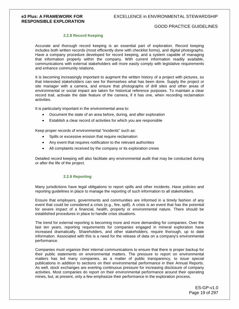
e3 Plus: A FRAMEWORK FOR EXCELLENCE in ENVIRONMENTAL STEWARDSHIP RESPONSIBLE EXPLORATION
GOOD PRACTICE GUIDELINES
ES-GP-v1.0 Page 19 of 297
2.2.8 Record Keeping
Accurate and thorough record keeping is an essential part of exploration. Record keeping includes both written records (most efficiently done with checklist forms), and digital photographs. Have a company procedure developed for record keeping, and a system capable of managing that information properly within the company. With current information readily available, communications with external stakeholders will more easily comply with legislative requirements and enhance community relations. It is becoming increasingly important to augment the written history of a project with pictures, so that interested stakeholders can see for themselves what has been done. Supply the project or site manager with a camera, and ensure that photographs of drill sites and other areas of environmental or social impact are taken for historical reference purposes. To maintain a clear record trail, activate the date feature of the camera, if it has one, when recording reclamation activities. It is particularly important in the environmental area to:
Document the state of an area before, during, and after exploration
Establish a clear record of activities for which you are responsible
Keep proper records of environmental "incidents" such as:
Spills or excessive erosion that require reclamation
Any event that requires notification to the relevant authorities
All complaints received by the company or its exploration crews
Detailed record keeping will also facilitate any environmental audit that may be conducted during or after the life of the project.
2.2.9 Reporting
Many jurisdictions have legal obligations to report spills and other incidents. Have policies and reporting guidelines in place to manage the reporting of such information to all stakeholders. Ensure that employers, governments and communities are informed in a timely fashion of any event that could be considered a crisis (e.g., fire, spill). A crisis is an event that has the potential for severe impact of a financial, health, property or environmental nature. There should be established procedures in place to handle crisis situations. The trend for external reporting is becoming more and more demanding for companies. Over the last ten years, reporting requirements for companies engaged in mineral exploration have increased dramatically. Shareholders, and other stakeholders, require thorough, up to date information. Associated with this is a need for the release of data on a company's environmental performance. Companies must organize their internal communications to ensure that there is proper backup for their public statements on environmental matters. The pressure to report on environmental matters has led many companies, as a matter of public transparency, to issue special publications in addition to sections on their environmental performance in their Annual Reports. As well, stock exchanges are exerting continuous pressure for increasing disclosure of company activities. Most companies do report on their environmental performance around their operating mines, but, at present, only a few emphasize their performance in the exploration process.

e3 Plus: A FRAMEWORK FOR EXCELLENCE in ENVIRONMENTAL STEWARDSHIP RESPONSIBLE EXPLORATION
GOOD PRACTICE GUIDELINES
ES-GP-v1.0 Page 20 of 297
Although major companies are accustomed to issuing environmental or sustainability reports, junior companies generally are not. It is recommended that smaller companies include a section on their environmental performance in their annual reports. If it is being handled well, it may distinguish a company from the competition. Such a section might include environmental, health and safety statistics, plus a discussion of any socioeconomic issues. Explain any problem areas and the actions taken to rectify them. In addition to information on exploration activities, it is important that monthly reports from an exploration project contain:
A summary of environmental and socioeconomic performance
The provision of statistics concerning, for example, the number of drill holes capped compared to the number drilled
The guiding principle of responsible exploration should be transparency, to the extent that it does not prejudice confidentiality and exploration competitiveness. At the conclusion of any exploration program, complete a project environmental report and be prepared to file it with the relevant authorities, either separately, or as part of a standard project drilling report. In this fashion, relevant information can be made available to other stakeholders and the public.

e3 Plus: A FRAMEWORK FOR EXCELLENCE in ENVIRONMENTAL STEWARDSHIP RESPONSIBLE EXPLORATION
ARCHAEOLOGICAL AND CULTURAL SITES
ES-AC-v1.0 Page 21 of 297
3.0 Archaeological and Cultural Sites
From time to time, exploration crews may become aware of, or suspect that, sites of archaeological or cultural significance are located on lands to be explored, or which are being explored. This is a critical issue that must be addressed during the planning or execution of any exploration program. Failure to do so may create serious legal difficulty and lead to significant conflict with local people. There is no surer way of creating conflict than desecrating, however unintentionally, a grave or a place of worship. Many jurisdictions have laws and regulations pertaining to the protection of archaeological and cultural sites. As professionals, explorationists must have knowledge of these laws and be in compliance with them.
Figure 8 This First Nations cemetery is located within the Manitoba Nickel Belt of northern Canada and is accessible only by water, approximately 60 km. from the nearest community. Such a site must be honoured and respected during any exploration program. © Barry Simmons
For purposes of this discussion, archaeological sites are considered to be sites of prehistoric or historic significance. Significant cultural sites, while including the above, are more difficult to define. They may be much more recent but of importance to the culture and heritage of the
peoples who have occupied or used the lands under exploration. In many cases, this occupation and use may be by indigenous people. Cultural sites might even include prominent landmarks, such as hilltops and other local topographic features. In some areas of the world, these cultural sites may be important evidence to support land claims. It should be emphasized that explorationists must exercise respect for such sites, since they represent irreplaceable and non-renewable resources. The record is unique, finite, and fragile. It is particularly important to recognize that the heritage of indigenous people will likely constitute the greater part of the archaeological record in many areas that may be explored for mineral potential. There are both cultural and spiritual links between indigenous people and the archaeological record that must be honoured and respected during mineral exploration programs. There are a number of practical steps that can be taken by mining companies to ensure compliance with the above requirements and principles.
1. Become aware of any laws and regulations pertaining to the protection of archaeological/cultural sites within the area of planned exploration. Depending on the jurisdiction, contact the local federal, provincial, or territorial government office. All exploration conducted must be in compliance with these laws and regulations.
2. During the planning stage, contact a professional archaeologist or anthropologist at the
appropriate government office, university, or museum closest to the project lands if there is any suspicion about, or knowledge of, the existence of sites of archaeological or cultural significance on the property. Follow the recommendations of this professional (and the previously mentioned laws and regulations) to determine if an exploration program is feasible, and how it should be conducted to protect any sites of significance. It

e3 Plus: A FRAMEWORK FOR EXCELLENCE in ENVIRONMENTAL STEWARDSHIP RESPONSIBLE EXPLORATION
ARCHAEOLOGICAL AND CULTURAL SITES
ES-AC-v1.0 Page 22 of 297
is often desirable to also contact the local community, especially indigenous groups, to inquire about the possible presence of such sites.
3. If a possible or suspected site is discovered during the exploration program, one should
immediately stop work, cordon off a reasonable distance around the site (or such distance as required by law), photograph the site for the record and contact an archaeological or anthropological professional, as well as the representative of the local indigenous community (usually a respected Elder). The site must remain undisturbed until investigated and documented by a recognized archaeological or anthropological professional. Under no circumstances should the exploration crew cause any disturbance or remove any relics from the site. Ensure compliance with any and all laws or regulations pertaining to such a site.
4. Follow the recommendations of the professional archaeologist or anthropologist and the
protocols agreed to with the local Elder regarding further protection of the site. For the record, photograph the site again upon completion, or temporary halt, of the exploration program.
These guidelines are very broad in scope and are not meant to represent definitive procedures for identifying or protecting sites of archaeological and cultural significance. Just as a professional outside the area of mining expertise could not recommend the most appropriate tools for exploration, EES cannot fully describe the methods for protecting these sites. It is the responsibility of the exploration company to ensure compliance with the law, that the appropriate professionals are consulted and that the appropriate procedures are taken to protect any and all sites of archaeological and cultural significance. Access to knowledge from the past is an essential part of the heritage of everyone; as professionals, members of the mining industry have a responsibility to protect this knowledge.
Figure 9 This cave in Queensland, Australia has been used for ochre extraction by indigenous people for generations. Such a site must be protected during exploration. © Noranda/Falconbridge

e3 Plus: A FRAMEWORK FOR EXCELLENCE in ENVIRONMENTAL STEWARDSHIP RESPONSIBLE EXPLORATION
PLANNING NEEDS
ES-PN-v1.0 Page 23 of 297
4.0 Planning Needs
In its early stages, exploration generally has a low environmental and socioeconomic impact. Consequently, the need for rehabilitation is modest and it is possible to take the steps to remediate a disturbance quickly. As more detailed exploration proceeds, the impacts increase correspondingly, as do the requirements for effective mitigation. EES encourages a proactive way of looking at the issue of environmental impact - to avoid it in the first instance wherever possible. This proactive approach also encourages taking into account the total cost of a program, rather than just the direct cost of carrying out a particular activity. Proper planning and consideration may result in new and improved approaches. Asking whether a program will have more or less impact on the natural and social environment may lead to a decision to use different, perhaps newer, technology to achieve the same aim. This section, which is abbreviated from the Management Essentials portion of the EES Fundamental section of the EES Web site e-toolkit, provides the explorationist with guidelines on how to prepare, conduct, and complete exploration activities with minimal environmental and socioeconomic impact. Refer to the more detailed treatment of these topics under Management Essentials in the EES Fundamentals section of the EES Web site.
4.1 Basic Elements
In the planning stages, before initiating any exploration program, it is important to consider a number of factors. The topics itemized below are fundamental to the design of any exploration program and it is important that they be addressed properly.
4.1.1 Exploration Code of Conduct
An explorationist must earn a "social license to operate" in any area where mine development is being considered. Steps to obtain that license, by focusing upon proper conduct, start at the outset of exploration activities in the area. Proper conduct consists of:
Addressing environmental and socioeconomic challenges
Understanding and dealing with the concerns of local communities
Complying with the relevant mining legislation, and accepting and discharging corporate responsibility
When entering an area for the purpose of mineral exploration, there are two challenges to face, beyond those of the exploration process itself. These challenges are environmental and socioeconomic in nature.
It is important that exploration crews in the field ensure that:
Both the technical and socioeconomic issues are dealt with in as rigorous and careful a manner as possible, so as to minimize adverse impact upon the local area, its residents, and also the company that they work for

e3 Plus: A FRAMEWORK FOR EXCELLENCE in ENVIRONMENTAL STEWARDSHIP RESPONSIBLE EXPLORATION
PLANNING NEEDS
ES-PN-v1.0 Page 24 of 297
They recognize the need to "tread lightly" in any area, and from the outset are receptive and sensitive to local concerns
Local communities are often concerned about an exploration program in their vicinity because of concerns that the program will cause damage to their land. It is important that a company demonstrates by its conduct not only that the initial impact will be minimized, but also that any land that is impacted will be remediated or reclaimed effectively. Failure to adhere to a proper code of conduct will not only damage the company or entity responsible for it, but will also adversely affect the mining industry as a whole. Mining Acts and other legislation generally confer rights of ownership or access to mineral lands. However, local communities have the right to be properly informed about exploration activities in their area. Land ownership can be a complicated issue in some parts of the world, especially in areas where Aboriginal people and communal land are involved.
4.1.2 Planning
When contemplating a program of exploration work, it is necessary to plan from the beginning to recognize the actual and potential impacts of the programs. This requires a change in mindset from "How do we mitigate the impact of the program as we carry it out?" to one of "How do we pre-plan our program to have the least adverse impact upon its surroundings?" It is important to take into account the total costs of an exploration program, including the costs required to:
Conduct the exploration, whether trenching, drilling or soil sampling
Remediate or reclaim any environmental impact
Satisfy the concerns of local communities There will inevitably be conflict at times between the needs of the exploration program and the requirements of environmental stewardship. It is important to ensure that:
Exploration imperatives do not ride roughshod over environmental issues
Environmental professionals are involved in the design of any program at an early stage, so that their input can be considered
Baseline studies are always conducted prior to any major disturbance of the natural surroundings
4.1.3 Due Diligence
When acquiring a mineral property (or any interest therein), a company assumes the responsibility to become knowledgeable about and financially responsible for, what is acquired. If an acquired property has environmental contamination, there may well be liability for the cost to reclaim the site to an acceptable level, even if the company was not aware of the problem. In order to protect the company‟s interests, therefore, it is essential to determine the characteristics of the property of interest prior to purchase or other involvement, and exercise due diligence. Due diligence can be fulfilled by a detailed data review carried out to establish the environmental, and if appropriate, the socioeconomic risks attached to the property. By obtaining a good understanding of environmental and socioeconomic issues in any potential target property, a company can better prioritize exploration targets and property purchases, and help protect itself against future environmental liabilities. A review of the existing condition of the
e3 Plus: A FRAMEWORK FOR EXCELLENCE in ENVIRONMENTAL STEWARDSHIP RESPONSIBLE EXPLORATION
PLANNING NEEDS
ES-PN-v1.0 Page 25 of 297
property and its history will also help to prioritize exploration targets and minimize future expenditures for historic damages. This is particularly important at brownfield sites (properties that were previously developed or explored) that are being considered for exploration purposes. In remote wilderness areas with no previous exploration activity, it is highly unlikely that there would be any reclamation liability on any property acquired. In fact, the natural condition provides a baseline against which any future development and subsequent reclamation can be modeled. In such cases however, it is important that environmental baseline studies be initiated prior to extensive activities on the site. This will provide support for any reclamation work to be done. At all other properties, including sites previously explored, there is the potential that past or current activities may require reclamation and impose an environmental or socioeconomic liability on the property. Any such liability may be transferred to the company, should it choose to acquire the property.
4.1.4 Legislation and Permitting
There is such a variety and range of legislation around the world, and it changes so frequently, that EES has made no attempt to list or catalogue any of it. Where there is unclear, poor, or no legislation, one might want to apply the practices used in developed countries (e.g., those of Canada or Australia). Before commencing exploration, it is important to:
Become familiar with the relevant and applicable legislation
Ensure that all permits required are obtained in a timely manner
Permits are usually required for exploration itself (e.g., access to the land) and other related activities (e.g., camp construction, drilling) and these must be obtained in a timely manner before the project is undertaken.
These permits may also include:
Plans for closure
Removal of equipment and buildings used in the program
In general, the “bush rule” applies: take out what is brought in, unless there are very good reasons (e.g., future use) for not doing so. Some countries (e.g., Australia) may require, as a condition for issue of a permit, a statement that an anthropological study has been completed with the local Aboriginal group, to identify any cultural or religious sites. In exploration for some commodities, permits may be required for export of samples for analysis or processing.
4.2 Operational Aspects
As the exploration program proceeds, there are several issues that are necessary to take into account. The manner in which these are incorporated will affect the conduct of the program; the exploration team should understand the importance of these issues.
e3 Plus: A FRAMEWORK FOR EXCELLENCE in ENVIRONMENTAL STEWARDSHIP RESPONSIBLE EXPLORATION
PLANNING NEEDS
ES-PN-v1.0 Page 26 of 297
4.2.1 Community Relations
Community relations in the mining and exploration industry have evolved from simply consulting with an affected community, to active engagement with the community to resolve issues. An engaged community role reduces the risk of conflict around mineral exploration projects through:
Effective interaction with the community
Establishment of a proper dialogue that can lead to an informed "social license to operate"
Exploration programs must not simply be "imposed" upon local communities. For exploration programs to be successful, they must be integrated with the local community as far as possible. When the local community experiences tangible benefits, the residents will be more likely to understand, and therefore support, the longer-term benefits of a project. It is very important for an explorationist, as an individual or a company, to spend enough time to understand the real local issues. The initial contact with local communities must be well thought out. For example, this contact might involve a trusted associate or intermediary within regional government introducing the exploration team to the local decision-makers. If field crews are wandering all over an area collecting soil samples, or flying an airborne survey, they may cause just as many local problems as a drill campaign. Therefore, dialogue should be commenced very early on in the exploration program. It is critical to develop trust on both sides of the discussion, which may be a relatively slow process. This Community Relations section is a condensation of the much more thorough treatment of the subject presented in the section entitled Community Engagement. A review of that section will provide more detailed guidance on this important topic.
4.2.2 Contractor Selection and Management
Companies now routinely engage contractors and subcontractors to carry out much of the specialized exploration work. Even geological mapping and sampling may be contracted out to consultants with specific experience. If contractors adversely affect either the environment or local community relations, the company employing them is liable. It is important to:
Pay the same careful attention to the selection and management of contractors and subcontractors as to company employees.
Ensure that contractors adhere to the same code of conduct as company employees. Consider including contractor employees in any environmental, community relations, or health and safety training programs that are implemented.
4.2.3 Health and Safety
Provide a safe workplace for employees, and ensure that all employees are aware of health and safety risks. This is particularly important in the exploration stage of work, since personnel are often operating in difficult conditions and may be quite remote from medical help.

e3 Plus: A FRAMEWORK FOR EXCELLENCE in ENVIRONMENTAL STEWARDSHIP RESPONSIBLE EXPLORATION
PLANNING NEEDS
ES-PN-v1.0 Page 27 of 297
Many companies have produced a "Health and Safety Manual" or similar document, which is required reading for all exploration crews. EES has not attempted to duplicate the issues dealt with in Health and Safety Manuals. It is important to provide the company‟s Health and Safety Manuals, as well as instruction and planning, to employees and field crews, to ensure that they follow the policies and procedures in those manuals. It is also important to require contractors and subcontractors to adhere to these policies. There should be visible commitment by the most senior executives of the company to good practice through word and deed.
4.2.4 Wildlife
The scope of Health and Safety also covers the protection of personnel from wildlife, as well as the protection of wildlife. All field personnel should ensure that they:
Are educated about the potential of wildlife to affect, and be affected by, exploration activities in any particular area
Have access to local specific knowledge of the dangers where appropriate
There may also be requirements in permits or licenses to report wildlife encounter incidents to the appropriate authorities, and to abide by their instructions. As a general rule, the killing of large wildlife (e.g., bears) is prohibited as part of local legislation or permitting, unless the appropriate authorities give specific permission. Hunting by exploration crews should be prohibited, and fishing is strictly regulated in most jurisdictions. Government representatives may seek access to the exploration project from time to time. Such inspections will determine whether or not the program is abiding by the requirements of its permits.
4.3 Policies and Reporting
Whenever carrying out an exploration program, appropriate policies and reporting procedures should be in place. This section outlines the critical elements involved.
4.3.1 Fire Prevention, Policy, and Response
Permits required for the work to proceed may prescribe the response to fire hazards in the exploration area. In addition, the following precautionary measures are necessary:
Firefighting equipment in camps must meet local regulations.
Properly functioning fire extinguishers, sand pails, etc., must be present in a camp.
Fire drills should be carried out periodically.
Everyone in a camp must be aware of the location of extinguishers and firefighting equipment. Permits for camp construction may specify the layout of the buildings and tents to meet fire requirements, and the camp design must take these into account. The use of open fires should be avoided, except for garbage disposal purposes if allowed by local regulations, and then only in a proper pit or container.

e3 Plus: A FRAMEWORK FOR EXCELLENCE in ENVIRONMENTAL STEWARDSHIP RESPONSIBLE EXPLORATION
PLANNING NEEDS
ES-PN-v1.0 Page 28 of 297
4.3.2 Training
There is little use in having policies and practices set out in company manuals or written policy, if they are not implemented. Employee training programs should be run in the field and performance should be monitored, to ensure that employees perform according to company policies. Contractors may have their own policies and procedures. It is the company‟s responsibility to ensure that they are equivalent to, or better than, corporate policies and procedures.
4.3.3 Reviews and Audits
When carrying out exploration, it is important that a company performs its own assessments of employees' environmental performance. Periodically review policies, to ensure that the work is consistent with current practice.
4.3.4 Record Keeping
Accurate and thorough record keeping is an essential part of exploration. Record keeping includes both written records (most efficiently done with checklist forms) and digital photographs. Wherever possible, photographs of drill sites and other areas of environmental or social impact should be taken before and after the exploration program so that the location is clear. The date feature of the camera should be activated. Also, it is important to keep proper records of environmental "incidents", such as spills or excessive erosion that may require reclamation, or any event that requires notification of the relevant authorities.
4.3.5 Reporting
The demand for external reporting is growing. Nowadays shareholders require "all the information, all the time". Although major companies are accustomed to issuing environmental or sustainability reports, junior companies generally are not. It is important that smaller companies include a section on their environmental performance in their annual reports. Many companies are now emphasizing their performance, even from the earliest stages of the exploration process. Ensure that employers, governments, and communities are informed in a timely fashion of any event that is, or has the potential to become, a crisis (e.g., a fire or spill). A crisis is an event that has the potential for severe impact of a financial, health, property, or environmental nature. It is necessary to have policies and reporting guidelines in place to handle crisis situations. The guiding principle of responsible exploration is transparency. A project environmental report should be completed at the conclusion of any exploration program. The company should be prepared to file it with the relevant authorities, either separately or as part of a standard project drilling report. In this fashion, the information will be accessible to other stakeholders.
e3 Plus: A FRAMEWORK FOR EXCELLENCE in ENVIRONMENTAL STEWARDSHIP RESPONSIBLE EXPLORATION
LAND DISTURBANCE
ES-LD-v1.0 Page 29 of 297
5.0 Land Disturbance
This section describes the natural causes and consequences of erosion, and how exploration activities can accelerate erosion processes. It then details the steps to take to control erosion during exploration activities. In addition, it explores the unique vulnerabilities of special terrains to erosion. Erosion is the wearing away of the land surface in response to natural forces such as wind and rain. These forces cause the materials of the earth's surface to loosen, dissolve, or wear away, then to be transported from one place to another by natural agents. The result is a change in the shape, and often the usefulness, of the land surface. Erosion is accelerated by exploration activities. Understanding the causes and consequences of erosion makes it possible to better evaluate and select methods to mitigate and control the impact of exploration.
5.1 Causes of Erosion
The natural forces of wind, water, ice and mass wasting (gravity) cause soil and rock particles to erode. Exploration activities can exacerbate the natural processes of erosion, because disturbance of the vegetation, soil, bedrock, and permafrost can alter surface drainage patterns. Climate, topography, soil type, vegetation, size of area, and length of time exposed to eroding forces, all affect the rate and degree of erosion. In particular, regions characterized by arid climate, high rainfall, steep slopes, fine impervious soils, low vegetative cover, or those receiving rapid melt from snow pack, are susceptible to high rates of erosion. The following sections identify the various causes of erosion, and describe their effects upon the land surface. Wind Wind is a powerful agent of erosion. Winds with low velocities of 13-15 km/h at ground level can remove soil particles from a dry surface. Removal of the vegetative cover can result in the complete loss of topsoil layers due to wind erosion. Wind can also entrain (carry along) soil particles, forming nuisance dusts, which cause health problems and unwanted accumulation of sediment. Erosion due to wind is greater in arid regions. When working in regions highly susceptible to wind erosion, it is vital to preserve the vegetation. Water and Ice Water erodes the Earth's surface in several ways. These include:
Wave action
Rainfall impact
Snow and ice buildup
Surface runoff

e3 Plus: A FRAMEWORK FOR EXCELLENCE in ENVIRONMENTAL STEWARDSHIP RESPONSIBLE EXPLORATION
LAND DISTURBANCE
ES-LD-v1.0 Page 30 of 297
Direct precipitation (such as heavy rainfall) breaks apart rock particles and loosens soil, as a result of the forces of impact. The buildup of snow and ice contributes to erosion in three ways:
Water that seeps into cracks of rocks can break rock when it freezes and expands
Glaciers (large bodies of ice), while slowly moving over the land surface, scrape off both soil and rock
Melting ice and snow produce large volumes of moving water (runoff) during the spring thaw
There are four forms of erosion that result from surface runoff:
Sheet erosion is due to sheet flow of water across a uniform surface and removal of thin layers of soil.
Rill erosion is caused by concentrated or repeated runoff that results in the formation of small channels, typically 2.5-3 m below the top of fill slopes.
Gully erosion results in the formation of deep channels and is caused by concentrated or high-velocity runoff.
Catastrophic erosion is caused by mudslides or landslides, which are in turn due to water building up in the soil and subsoil. This can be a health and safety risk as well as an environmental issue causing, for example, the catastrophic failure of a drill site.
Each of these can result in changes to the pre-existing drainage pattern. The sediment that is carried from the land surface into waterways by runoff can degrade the downstream water quality, affecting the aquatic ecosystems. Suspended sediment can inhibit photosynthesis and plant growth, due to decreased light penetration. It can also clog fish gills. Excessive sedimentation changes the stream substratum, leading to channel infill and damage of spawning grounds. In addition to sediment, the runoff can carry away pesticides, petrochemicals, heavy metals, road salts, and other pollutants. Not only are these pollutants toxic to humans and fauna, they negatively affect soil fertility and plant water uptake. Exploration activities can affect the intensity of erosion resulting from rainfall and surface runoff. Concentrated runoff on denuded areas or areas of unstable soils causes the most severe erosion as a result of water movement. It is therefore very important to ensure that the minimum area of vegetation and topsoil is disturbed during an exploration program, so that the existing protective cover is maintained as far as possible. This is particularly important in areas of high rainfall. Gravity Mass wasting occurs when gravitational forces overcome the natural resistance of a mass of soil or rocks, without the aid of a flowing medium such as air at normal pressure, water, or glacier ice. A landslide is an example of mass wasting.
Vegetation Clearance Vegetation inhibits erosion. Plant roots hold the topsoil in place, while leaves protect the surface against the erosive action of rainfall and act as barriers to the wind. Topsoil contains valuable nutrients, micro-organisms, minerals, seeds, and rootstocks - important elements for successful site rehabilitation after exploration activities are completed.

e3 Plus: A FRAMEWORK FOR EXCELLENCE in ENVIRONMENTAL STEWARDSHIP RESPONSIBLE EXPLORATION
LAND DISTURBANCE
ES-LD-v1.0 Page 31 of 297
When soil is moved or loosened it:
Washes away with the runoff
Creates sediment in streams
Loses its nutrients after a period of time
Erosion frequently starts with the cutting, clearing or removal of vegetation. Once the vegetative cover is gone, erosion is accelerated. The longer the exposed area is subject to erosive forces, the more severe the effect. Reestablishment of the native flora will be more difficult if the vegetation has been completely removed, and this may result in further degradation of habitat.
Soil Disturbance
Soil characteristics can affect the rate of erosion. Fine-textured soils are prone to wind and water erosion, once exposed by removal of surface organic layers. Fine-textured and wet soils are more susceptible to rutting than drier, medium, or coarse soils. Disturbed or compacted soils may interrupt soil moisture movement, and this can inhibit successful remediation activities.
Bedrock Disturbance Disturbance of the bedrock changes drainage and runoff patterns, which may increase the rate of erosion. Trenching is the exploration activity that most disturbs bedrock.
5.2 Consequences of Erosion
Erosion can result in
Degradation of surface waters with eroded sediment.
Altered patterns of surface water flow and drainage.
Increased stream flow velocity or channelling flow (channelization).
Loss of valuable and productive topsoil.
Generation of non-point source pollution (mainly sediment, but also spilled fuels).
Destruction of natural habitat (on land and in aquatic ecosystems).
Compaction of soil, which reduces the capacity of water to infiltrate soil resulting in higher runoff volumes.
5.3 Methods of Erosion Control
Line cutting and other exploration activities disturb the landscape and can accelerate the erosion of unstable soils. It is essential to introduce appropriate erosion and sediment control structures and procedures into activities, even as early as the survey stage. The goal should be to expose the smallest practical area of land, for the shortest possible time, to eroding forces. Reaching this goal requires planned exploration activities, anticipating the needs of the exploration program. Careful planning facilitates the eventual rehabilitation process. As a general rule, minimize vegetation, soil, and bedrock disturbance and exposure to wind and water. There are many different erosion and sediment control structures available to you which, if properly designed, installed and maintained, will effectively reduce the transport of sediments,
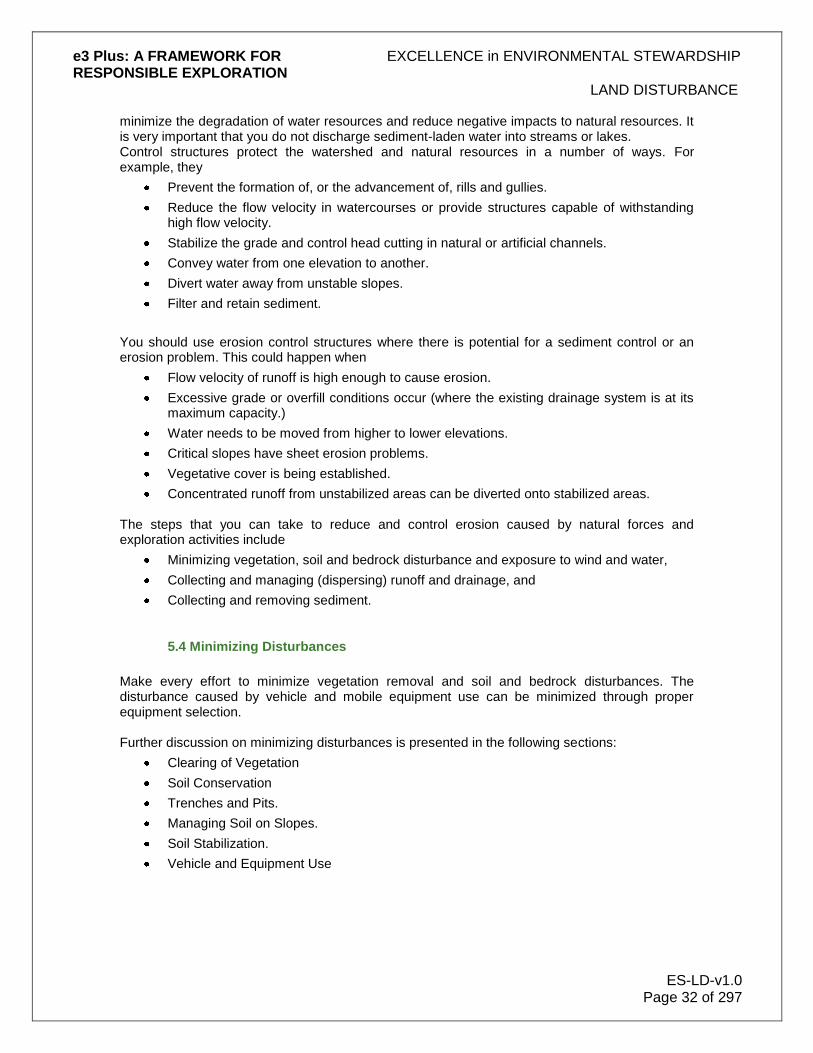
e3 Plus: A FRAMEWORK FOR EXCELLENCE in ENVIRONMENTAL STEWARDSHIP RESPONSIBLE EXPLORATION
LAND DISTURBANCE
ES-LD-v1.0 Page 32 of 297
minimize the degradation of water resources and reduce negative impacts to natural resources. It is very important that you do not discharge sediment-laden water into streams or lakes. Control structures protect the watershed and natural resources in a number of ways. For example, they
Prevent the formation of, or the advancement of, rills and gullies.
Reduce the flow velocity in watercourses or provide structures capable of withstanding high flow velocity.
Stabilize the grade and control head cutting in natural or artificial channels.
Convey water from one elevation to another.
Divert water away from unstable slopes.
Filter and retain sediment.
You should use erosion control structures where there is potential for a sediment control or an erosion problem. This could happen when
Flow velocity of runoff is high enough to cause erosion.
Excessive grade or overfill conditions occur (where the existing drainage system is at its maximum capacity.)
Water needs to be moved from higher to lower elevations.
Critical slopes have sheet erosion problems.
Vegetative cover is being established.
Concentrated runoff from unstabilized areas can be diverted onto stabilized areas. The steps that you can take to reduce and control erosion caused by natural forces and exploration activities include
Minimizing vegetation, soil and bedrock disturbance and exposure to wind and water,
Collecting and managing (dispersing) runoff and drainage, and
Collecting and removing sediment.
5.4 Minimizing Disturbances
Make every effort to minimize vegetation removal and soil and bedrock disturbances. The disturbance caused by vehicle and mobile equipment use can be minimized through proper equipment selection. Further discussion on minimizing disturbances is presented in the following sections:
Clearing of Vegetation
Soil Conservation
Trenches and Pits.
Managing Soil on Slopes.
Soil Stabilization.
Vehicle and Equipment Use

e3 Plus: A FRAMEWORK FOR EXCELLENCE in ENVIRONMENTAL STEWARDSHIP RESPONSIBLE EXPLORATION
LAND DISTURBANCE
ES-LD-v1.0 Page 33 of 297
5.4.1 Clearing of Vegetation
There are important issues to consider when clearing trees or vegetation for surveys.
Do not clear land of vegetation more than 6 months in advance of when it is required
Avoid clear cutting and bulldozer blading
Where possible, drive over flattened vegetation, to preserve rootstock and prevent soil erosion
Limit the amount of clearing with heavy machinery.
Wherever possible, preserve the organic mat
Avoid cutting commercial plant species (presume someone is cultivating them)
Cut and remove unstable or snagged trees where they pose a danger to workers or could fall across the roadway.
Not leave trees leaning into marginal timber.
Leave large trees standing, if possible.
When constructing access roads or other facilities, weave roads around trees or relocate facilities to help reduce the visual impact of vegetation clearance.
Avoid removing vegetation adjacent to lakes, rivers and streams. Leave a buffer zone of undisturbed vegetation at least 10 metres wide on either side of the stream or waterway.
Cutting Vegetation Each jurisdiction will have local guidelines and permit requirements for cutting and removal of trees. Learn the regulations and ensure that all authorizations or permits have been granted before commencement of any work. As a general guideline, in the survey stage of the exploration process:
Cut vegetation close to ground level for safety reasons, to avoid dangerous “spikes” of stumps protruding.
Buck cut trees. The boles of trees should be cut from the stump at the root crown.
Saw felled trees into manageable lengths.
Trim overhanging vegetation to reduce the hazard of protruding branches.
Do not fell live saplings of any species over 150 mm in diameter unless absolutely necessary.
Ensure cutters are trained to recognize and avoid cutting any native species that are subject to local regulations.
Minimize cutting in sensitive (e.g. alpine) areas.
Remove all introduced debris (e.g. bottles, cans, paper).
When using power equipment:
When changing oil, collect waste oil and take it to an appropriate disposal area.
Do not dump used oil in the bush.
Ensure that appropriate fire hazard control materials are on-site. Keep a knapsack filled with not less than 10 L of water, or a powder-type extinguisher of not less than 1 kg capacity, within reach on all worksites where chainsaws, power augers, and other gasoline-driven machinery are used.
Be aware of any fire bans.
When using a portable generator, keep the exhaust area clear of leaves and twigs.

e3 Plus: A FRAMEWORK FOR EXCELLENCE in ENVIRONMENTAL STEWARDSHIP RESPONSIBLE EXPLORATION
LAND DISTURBANCE
ES-LD-v1.0 Page 34 of 297
Line Cutting and Surveys
When establishing a grid and conducting ground surveys, ensure that:
Cut lines or walking tracks do not exceed 1 m in width.
Access to cut lines is discreet, in order to reduce the possibility of subsequent misuse by unauthorized users (for environmental as well as safety reasons).
Cut lines are established using hand tools only (e.g., machete, fern hook, axe, chainsaw).
Biodegradable tape is used in preference to ordinary plastic type. This tape will last at least 2 years, but will eventually disintegrate.
Only small lengths of tape should be used. “Streamer” type markers of several metres of tape are not necessary.
Wherever possible, grids in sensitive areas are only pegged and flagged with tape. On completion of the program, ensure that:
All equipment, including wires, is removed from the grid.
Hipchain cotton is removed from grid lines, as birds can become entangled in this line.
Wherever possible, conspicuous markers such as pegs and tape are removed, especially from the beginning of grid lines. Special attention should be given to this in sensitive areas.
All pickets are removed from ice on water courses prior to break-up.
Managing Removed Vegetation
Vegetation cut during the establishment of lines can be used in a number of ways, including the acceleration of the process of revegetation disturbed areas. Consider the following procedures in this regard:
Store removed vegetation so that it can be later used as a seed source, moisture retention aid, and shade for new growth during reclamation.
Incorporate some of the cut timber and slash into a road sub grade and dispose of the remainder of the slash by scattering, piling and burning, or burying.
Use some of the vegetation that was removed as mulch.
Lop or limb cut bulldozed trees and scatter the branches and limbs
Use some of the removed vegetation as mulch.
Cut slashed vegetation (slash) into less than 4 m lengths, cover with at least 1 m of soil, reseed, and fertilize.
Dispose of slash such that it does not degrade aquatic habitats or pose a fire hazard.
Determine if slash burning is permitted. Never burn during dry periods or when there is a high fire hazard. Scatter or bury residues from burning.
5.4.2 Soil Conservation
In order to protect and support vegetation that inhibits surface erosion, it is critical to conserve topsoil in disturbed areas. Topsoil contains valuable nutrients, micro-organisms, minerals, seeds, and root stocks, which are important for reclamation. Of particular importance is the seed resource of native species contained in topsoil. This seed resource is essential to restoring the diversity of plant species within the disturbed area.

e3 Plus: A FRAMEWORK FOR EXCELLENCE in ENVIRONMENTAL STEWARDSHIP RESPONSIBLE EXPLORATION
LAND DISTURBANCE
ES-LD-v1.0 Page 35 of 297
Plan all activities that disturb the ground surface in such a way that the amount of topsoil that is moved is minimal. Stockpiling Topsoil Stockpile topsoil separately from subsoil and protect it for future use in reclamation. Consider the following factors before disturbing topsoil:
If there is a heavy mulch of decaying vegetation overlying the soil layer, it should be removed first and stockpiled separately.
Topsoil usually constitutes the top 10-20 cm of soil, but in some areas may be very shallow.
Excavated soil should be stockpiled for reapplication to disturbed areas.
Topsoil and the subsoil should be stored in separate piles no higher than 1-2 m. This ensures proper aeration for soil fauna. (Good practice for topsoil storage height from various sources ranges between 0.6 m and 3 m. The 1-2 m height has been chosen here as a reasonable midpoint within this range.)
Soil should be covered with permanent or temporary vegetation to prevent erosion.
Subsoil needs to be reapplied before the topsoil.
5.4.2.1 Trenches and Pits
Ideally, locate trenches (or "costeans") and pits to avoid large trees (>150 mm in diameter). Where this is not possible, pre-cut these trees and move them to one side for salvage. Always strip topsoil (including scrubby vegetation and the organic mat) and move it to one side of the trench into long, narrow piles, no more than 1-2 m high. If topsoil is piled into larger heaps, oxygen cannot reach the centre of the pile, and useful soil organisms die. The soil then becomes sterile and loses nutrients. It is important to store soil properly, wherever possible. Ensure that there is proper drainage through the topsoil piles, especially if they have to lie for several months before rehabilitation work commences. Topsoil is easily erodible, and must be protected from needless erosion loss by installing drainage, if required, and covering its surface to protect from wind erosion. On a slope, use a table drain or ditch uphill from the trench, to prevent the trench from filling up with water. On sloping sites provide drainage above trench and soil storage. Before designing and building trenches and pits, take into account the local conditions. The key steps in the construction and rehabilitation of trenches are illustrated below. Place subsoil and any excavated rock in separate piles, not on top of the topsoil. One easy method for small trenches is to place the topsoil on one side of the trench and subsoil on the other. If there is not enough room on one side of the trench for all of the subsoil, pile both the topsoil and subsoil on each side of the trench, but in separate piles. With small trenches, which are filled in on the same day or within a few days of being dug, there is no need to strip the topsoil from the area used to store the subsoil. As noted above, however, if the trench is large and will be left open for weeks or months, strip and store the topsoil from the subsoil storage area.

e3 Plus: A FRAMEWORK FOR EXCELLENCE in ENVIRONMENTAL STEWARDSHIP RESPONSIBLE EXPLORATION
LAND DISTURBANCE
ES-LD-v1.0 Page 36 of 297
For the safety of workers, bench the sides of large or deep trenches (>1 m deep) and consider the addition of shoring in unstable ground. The design of trenches is regulated in many jurisdictions and may require engineering advice. Never use bulldozers to dig trenches. Excavators and backhoes can do a far neater job. However, when a shallow scrape is needed to expose rock for examination, then a bulldozer may be the most suitable machine for the job. Replace scraped-off soil (if any) when the shallow "scrape" trench is no longer required. When refilling the trench, replace the rock and subsoil first, then cover it with the topsoil/vegetation mixture. Fill in trenches as soon as possible after the program has finished. Place all acid-producing waste rock back in the excavation or pit, and backfill it as soon as practical. Backfill all trenches and pits containing acid-producing waste rock with benign, low-permeability material topped with a compacted capping layer at least 1 m thick. Encourage new vegetation growth with the application of fertilizer and seeds. If topsoil is stored for longer than 3 months, the nutrients become depleted, and fertilizing will be needed to aid revegetation. If topsoil is stored longer than 6 months, seeding is beneficial.
Figure 10: Large trenches such as this one in West Africa can be hazards to both wildlife and people unless reclaimed. © Iamgold.

e3 Plus: A FRAMEWORK FOR EXCELLENCE in ENVIRONMENTAL STEWARDSHIP RESPONSIBLE EXPLORATION
LAND DISTURBANCE
ES-LD-v1.0 Page 37 of 297
Figure 11: Trenching can leave a major scar on the landscape unless reclaimed. The muck pile from this trench in Argentina will be used as backfill upon completion of work. © Iamgold.
5.4.2.2 Managing Soil on Slopes
On sloping sites, provide drainage above trench and soil storage. Soils on slopes are susceptible to erosion. The rate of erosion increases as the angle and length of slope increases, due to higher flow velocities and a greater chance that channels will develop. Soil texture is also a factor to be considered in assessing susceptibility to erosion. The following table sets out some of the criteria that can help determine this assessment.
Table 2: The Rate of Erosion
Soil Texture
Degree of Slope
0 – 3o
0 – 5% 3 – 5
o
5 – 9% 5 – 17
o
9 – 30% 17 – 31
o
30 – 60% >31
o
>60%
Fine Moderate High High High High
Fine to Medium Moderate Moderate High High High
Medium Low Low Moderate High High
Medium to Coarse Low Low Moderate Moderate High
Coarse Low Low Low Moderate High
In order to reduce the velocity of the runoff, contour a long (>30 m) or steep slope and incorporate benches, terraces, or breaks in the slope. Careful selection of trail, track, and road location along slope contours is important to reduce the potential for erosion and its impacts.

e3 Plus: A FRAMEWORK FOR EXCELLENCE in ENVIRONMENTAL STEWARDSHIP RESPONSIBLE EXPLORATION
LAND DISTURBANCE
ES-LD-v1.0 Page 38 of 297
Activities on slopes should be conducted so as to maintain the vegetative cover as much as possible. Re-establish disturbed vegetation cover as soon as possible. In steep areas with slopes greater than 3:1, techniques other than revegetation may be required to stabilize the slope and prevent erosion. When constructing a trench on a slope:
Construct the trench along the slope contour, and include a ditch or drain at the ends to outlet flow to a level area or other stabilized discharge area
Place excavated materials on the sides of the trench, keeping topsoil and subsoil piles separated and protected from erosion
Install a drain on the upslope side of the trench to prevent runoff from eroding stockpiled topsoil and subsoil and flowing into the trench
If the trench is to be left open for a period of time, stabilize and revegetate the trench, slope, and the surrounding disturbance area as soon as practical
Reclaim trenches by filling with subsoil and topsoil and revegetation, as appropriate, at the end of the program
5.4.2.3 Soil Stabilization
Soil stabilization by re-establishing vegetation cover is the most cost-effective, long-term surface erosion control method, because it controls sediment at the source. Revegetate soil exposed during construction, and installation of a stream crossing following construction. Revegetation of approach ditches, cut slopes, and other disturbed areas reduces the possibility of stream sedimentation. Undertake revegetation immediately following completion of the work. Standard revegetation techniques include hand-broadcast or hydraulic seeding, and mulching using regionally adapted seed and mulch mixes. Select seed mixes that are less palatable to livestock, to minimize livestock activity at crossing sites. The timing of seed application is determined largely by the completion time of the construction or stream crossing installation. Seed all exposed soils in the vicinity of the stream crossing installation immediately following completion of construction, and reseed the site as necessary. Hydroseeding is the most efficient means for seeding steeper slopes. Mulching accelerates seedling development, and reduces the chance of seed being washed away by rainfall and runoff. When combined with hand-broadcast seeding, straw is a fast and cost-effective mulch substitute for dealing with smaller exposed areas near stream crossings. Apply seed and mulch by hand, independent of the seeding schedule, or by the method established for the rest of the road system. This practice can accelerate revegetation at higher-risk locations. Fibre-bonding agents are slurries of wood fibres and tackifiers (binding agents) that conform to the ground and dry to form a durable, continuous erosion control blanket that stays in place until vegetation is established. The fibre mats created are biodegradable and decompose slowly as vegetation is re-established. Like other forms of mulching, bonded fibre matrices hold seed and fertilizer in place, yet allow sunlight and plants to penetrate. Compared to conventional erosion control blankets, they require no manual labour to install, and are not subject to under-rilling or tenting, as can occur with erosion control matting and netting.
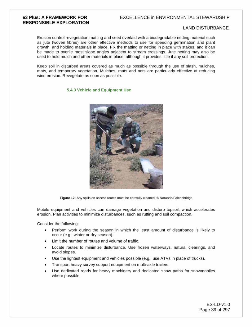
e3 Plus: A FRAMEWORK FOR EXCELLENCE in ENVIRONMENTAL STEWARDSHIP RESPONSIBLE EXPLORATION
LAND DISTURBANCE
ES-LD-v1.0 Page 39 of 297
Erosion control revegetation matting and seed overlaid with a biodegradable netting material such as jute (woven fibres) are other effective methods to use for speeding germination and plant growth, and holding materials in place. Fix the matting or netting in place with stakes, and it can be made to overlie most slope angles adjacent to stream crossings. Jute netting may also be used to hold mulch and other materials in place, although it provides little if any soil protection. Keep soil in disturbed areas covered as much as possible through the use of slash, mulches, mats, and temporary vegetation. Mulches, mats and nets are particularly effective at reducing wind erosion. Revegetate as soon as possible.
5.4.3 Vehicle and Equipment Use
Figure 12: Any spills on access routes must be carefully cleaned. © Noranda/Falconbridge
Mobile equipment and vehicles can damage vegetation and disturb topsoil, which accelerates erosion. Plan activities to minimize disturbances, such as rutting and soil compaction. Consider the following:
Perform work during the season in which the least amount of disturbance is likely to occur (e.g., winter or dry season).
Limit the number of routes and volume of traffic.
Locate routes to minimize disturbance. Use frozen waterways, natural clearings, and avoid slopes.
Use the lightest equipment and vehicles possible (e.g., use ATVs in place of trucks).
Transport heavy survey support equipment on multi-axle trailers.
Use dedicated roads for heavy machinery and dedicated snow paths for snowmobiles where possible.

e3 Plus: A FRAMEWORK FOR EXCELLENCE in ENVIRONMENTAL STEWARDSHIP RESPONSIBLE EXPLORATION
LAND DISTURBANCE
ES-LD-v1.0 Page 40 of 297
5.5 Managing Drainage and Runoff
Runoff is water that flows over land into the natural drainage system of the streams, rivers, and lakes in a region. Runoff contributes to erosion and the transport of soil into waterways. Exploration activities can disturb natural runoff and drainage patterns. Altering of drainage patterns through blockage or diversion can result in major changes to affected areas, such as the ponding of water, or the deprivation of water to other areas. Since drainage in arid regions usually occurs as sheet flow, it is important to ensure that any land and water disturbances do not result in channelization of surface runoff. Anticipate the consequences of all exploration activities, and take actions to control flow velocity, water volume, and resulting erosional effects. Bear in mind that it is generally better to spread out water than to make it concentrated. It may be necessary to divert uncontrolled surface water runoff around disturbed areas in order to minimize erosion (e.g., sheet wash, gullying). Construct drainage diversions before the start of road building or stripping and trenching activities. Pay particular attention to:
Road and track design and construction
Location of bridges and crossings
Use of culverts, ditches, and berms
Presence and steepness of slopes
5.5.1 Road and Track Design
Most jurisdictions have regulations governing road and track construction, and it is important to abide by them. There are also many practical and reasonable issues to consider when designing and building a track or road. Permits may be required for stream crossings, for example. To avoid project delays, take into account the time required for approval of all permits. The first step in planning access by road or track is to ascertain whether or not it is essential. Always use an existing road or track in preference to constructing a new one. This will prevent duplication, avoid unnecessary environmental interference, and reduce maintenance costs for the track. A well-planned road or track will cost less than one that is poorly placed and requires frequent maintenance. In designing a track, for instance, consider the anticipated volume and type of traffic. It is important to:
Avoid long uninterrupted slopes
Create crowned road surfaces
Select sites that will help prevent water from collecting and flowing along the road
The following sections explore many aspects of planning, design and construction of roads and tracks to take into consideration.
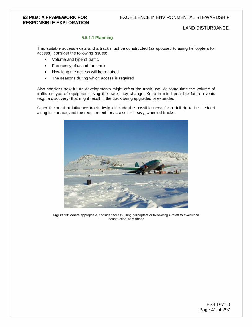
e3 Plus: A FRAMEWORK FOR EXCELLENCE in ENVIRONMENTAL STEWARDSHIP RESPONSIBLE EXPLORATION
LAND DISTURBANCE
ES-LD-v1.0 Page 41 of 297
5.5.1.1 Planning
If no suitable access exists and a track must be constructed (as opposed to using helicopters for access), consider the following issues:
Volume and type of traffic
Frequency of use of the track
How long the access will be required
The seasons during which access is required
Also consider how future developments might affect the track use. At some time the volume of traffic or type of equipment using the track may change. Keep in mind possible future events (e.g., a discovery) that might result in the track being upgraded or extended. Other factors that influence track design include the possible need for a drill rig to be sledded along its surface, and the requirement for access for heavy, wheeled trucks.
Figure 13: Where appropriate, consider access using helicopters or fixed-wing aircraft to avoid road construction. © Miramar

e3 Plus: A FRAMEWORK FOR EXCELLENCE in ENVIRONMENTAL STEWARDSHIP RESPONSIBLE EXPLORATION
LAND DISTURBANCE
ES-LD-v1.0 Page 42 of 297
Figure 14: Mobilizing the drill to a high altitude site in Peru. Access roads can be minimized using lightweight, modular drill rigs. © Kluane Drilling
Figure 15: If well-designed, access roads can be constructed with minimal land disturbance as in this example from Argentina. © Noranda/Falconbridge
5.5.1.2 Location
Take steps to select the location of a track carefully. Find possible routes for the track or road, first by using available maps and air photos, then by field inspection. Be careful to investigate the

e3 Plus: A FRAMEWORK FOR EXCELLENCE in ENVIRONMENTAL STEWARDSHIP RESPONSIBLE EXPLORATION
LAND DISTURBANCE
ES-LD-v1.0 Page 43 of 297
various possibilities or alternative sites for different parts of the proposed track, and walk the whole length of the proposed route, not just the beginning. In track planning:
Assess the potential visibility impact of different routes, not only from roadways, but also from local residential sites and vantage points in the neighbourhood.
Take visual impact into account in planning. Colour contrasts between soil and the underlying material can produce a high visual impact, which is not evident when the soil and underlying material are of the same colour.
Learn to recognize and avoid rare or valued tree species.
Establish control points first (e.g. creek crossings, saddles) to assist in the location of the track, then decide on the required gradient between the control points.
Where removal of trees is unavoidable, consider routes that minimize tree clearing. Try and mark both sides of the track by tying a "corridor" of tapes along the proposed route. This will greatly assist the earthmoving contractors in putting the track in neatly.
Avoid poor or difficult ground, such as:
Rock outcrops
Soaks (a natural depression holding rainwater)
Swamps
Generally, the best track locations are found on ridge tops or on bottom slopes just above the valley floor. It is better to keep off valley floors, as drainage is generally a problem in these locations. Recognize wet areas, which may not be wet at the time of inspection, by the type of vegetation present. Examples of vegetation found in wet areas include:
Peat
Buttongrass (Australia)
Bullrushes
In laying out a track:
Minimize the number of stream crossings.
Fit the track to the topography so that the earthworks disturbance is minimized.
Try to position tracks along the contours, and avoid sudden changes in gradient. Steep sections of tracks are prone to severe erosion - incurring high maintenance costs - and must have drainage systems (ditches and/or cross drains) put in during construction. Avoid building dead-level tracks, as water will pool on these flat sections and not drain properly.
Where topography permits, locate roads on old benches (provided they are not backslopes of old landslides), ridge tops and flatter slopes. Ideally, build tracks to a grade of not less than 1% (so water will run off), but not more than 5%, especially if constructed in erodible soils or clay areas where traction may be a problem in the wet.
When developing a new track off an existing roadway:
Ensure that the junction is discreet, but is also safe.
Ensure that traffic has a clear view at junctions.
Avoid junctions located just over the brow of a hill, or round a sharp bend on a main road.
Ensure that the entry angle between track and road is large and that the track includes a "dogleg" in the bush, close to the road, to reduce visibility where possible.

e3 Plus: A FRAMEWORK FOR EXCELLENCE in ENVIRONMENTAL STEWARDSHIP RESPONSIBLE EXPLORATION
LAND DISTURBANCE
ES-LD-v1.0 Page 44 of 297
Ensure that tracks constructed parallel to a major watercourse are some distance from the watercourse (check local regulations). The general rule is the larger the watercourse, the larger the margin of undisturbed vegetation to be left on the banks.
Protect watercourses in a manner consistent with regulatory and legislative guidelines. It is also important to:
Prevent heavy machinery from entering streamside reserves, except to cross the streams at defined crossing points. These streamside reserves are recognized as necessary for the protection of water quality.
Keep interference with the natural drainage to a minimum.
Build stream crossings at right angles to the stream.
5.5.1.3 Construction
When constructing a track:
As a general rule, pre-cut all fallen logs and saplings greater than 150 mm in diameter before pushing aside with dozer or excavator. Any commercial timber should be set aside for salvage.
Remove topsoil and vegetation and store in a long windrow, no higher than 1-2 m alongside the track.
Make sure the topsoil stockpile is out of the way of traffic. Ensure that drains are constructed through the stockpiled soil to allow runoff to escape; otherwise, valuable topsoil may be eroded.
Store subsoil (spoil) in a windrow (i.e. a long, low ridge) alongside the track, but do not pile this on top of the topsoil. Clear topsoil from the spoil storage area.
In many cases, pushing over trees in line with the proposed track may be preferable to cutting. Revegetation on roadsides (where a fallen log, with roots partly intact forms the roadside verge) is frequently improved by re sprouting from the tree trunk. The reason for pre-cutting is to avoid damage to peripheral vegetation from uncontrolled falling of large trees. On occasions, however, careful felling of trees can assist in stabilizing the road verge. This is mostly applicable in the construction of narrow tracks on moderate slopes. In general:
Do not make the track any wider than necessary.
Choose the smallest machine suitable for the job to restrict the width, or use an excavator.
Recognize that tracks made with excavators frequently are neater and require less rehabilitation work, although there are situations where a bulldozer is the more appropriate machine to use. Use excavators wherever possible, in conjunction with a bulldozer if necessary.
Observe that on steep slopes (>30°), some benching will probably be necessary.
In addition:
Limit vegetation clearance to the extraction site, and remove trees with the same precautions as for the track.
Do not needlessly remove vegetation from either side of a roadway.

e3 Plus: A FRAMEWORK FOR EXCELLENCE in ENVIRONMENTAL STEWARDSHIP RESPONSIBLE EXPLORATION
LAND DISTURBANCE
ES-LD-v1.0 Page 45 of 297
Ensure service areas are limited in size and number. Where possible, ensure construction service areas, fuel, equipment, vehicle depots, and campsites are confined to the future road alignment.
Do not use creek floors as tracks.
Fill and Road-Building Materials Always use fill from cuts wisely - do not push it over a bank and waste it. Try to compact the fill as much as possible, to minimize water penetration and to prevent the fill from washing away. When a demand for road building material is anticipated, locate a few good source sites, and develop these systematically. Do not poach fill and surfacing from along the road verges. Fill material can be obtained by slightly widening the track, and on some occasions this may be preferable to opening up a borrow pit next to the track. Always design road material pits to be compact, and inconspicuous from the roadway and from neighbouring vantage points, by judicious site selection, utilizing local landforms, leaving natural screens of vegetation, constructing mounds capped with topsoil, and revegetation.
5.5.1.4 Drainage
Water can quickly damage roads and tracks. To protect against this damage:
Repair drainage on existing roads
Install proper drainage systems on all tracks
This last point cannot be emphasized enough. A little money spent on adequate drainage in the beginning will save much time and money later on in repairing water damage. Table Drains and Cross Drains This section discusses the use and construction of table drains (ditches) which parallel the road or track, and cross drains that interrupt water flow on the track and/or channel water from table drains onto level, stable areas for dispersion. The aim of these is to prevent direct flow from roads or tracks into waterways. Table drains should be "dish-shaped", at least 30 cm (0.3m) deep and at least 60 cm (0.6m) wide. Dig them on the inside edge of the curve, or the uphill side of the track, and connect them to a properly constructed cross drain. Table drains should channel water into cross drains. Place cross drains at frequent intervals. On moderately steep slopes, construct cross drains every 30 m (or even closer). Of all the faults seen in poorly constructed tracks, the lack of cross drains is the most common. When installing drains:
Construct cross drains at approximately right angles across the track. They should be dish-shaped, about 0.6 m wide and 0.3 m deep. These drains are often damaged by the regular passage of traffic and need to be kept in a good state of repair.
Locate the cross drain at an angle to best intercept water from the table drain, and on a slight grade (1-3%) to pass the water from one side of the track to the other.
Ensure that table drains and cross drains are not "square in cross section", as can easily happen when drains are constructed with a backhoe or excavator. The preferred shape is that of a shallow dish, as it erodes much less easily.

e3 Plus: A FRAMEWORK FOR EXCELLENCE in ENVIRONMENTAL STEWARDSHIP RESPONSIBLE EXPLORATION
LAND DISTURBANCE
ES-LD-v1.0 Page 46 of 297
Mounds (Waterbars) Use "mounds" (also known as waterbars) to divert water off a track. These are made during track construction by piling up any available material - gravel, crushed rock, even soil - into a long "hump" across the track, rather like a "speed hump" used to force cars to slow down. The hump works by directing water flowing down the track off to one side, into a table drain or stabilized drainage area. Carefully maintain these mounds. The material to make the mound may be obtained by making a long spoon-shaped scrape 1-2 m in front of the mound during construction of the track. Waterbars should be constructed on all access roads to minimize rills and gullies. Water Flow Ensure that the dimensions of cross drains and table drains are adequate to cope with the volume of runoff. In easily eroded soils, water velocity in the drains should not exceed 0.5 m/sec. In more resistant soils, the velocity should not exceed 1.0 m/sec. When constructing drains, try to stick to the same gradients as used in track construction - between 1-5% slope wherever possible. Where substantial water flow is expected:
Line the drains with broken rock, half-pipes or concrete interlocking channels where they cannot cope with the volume of water.
Construct large cross drains and culverts in conjunction with a sediment trap or a pond into which the drainage water can collect, allowing sediment to settle out before flowing on, following the natural drainage channels where excessive silt loads are anticipated, or where water quality is an issue.
Locate culverts and cross drains where the runoff either filters through undisturbed forest soil or into natural drainage channels. If this is not possible, direct the discharge onto solid ground, not fill.
Remember to check drains and culverts frequently and unblock where necessary. A blocked culvert can cause massive washouts.
Culverts
Where culverts are necessary:
Lay culvert pipes on a very slight grade, not too flat or too steep. This is to minimize silting up of the pipes, which will occur if the pipes are too flat, and to control "scouring" of the culvert outlet, which will happen if the water flow is concentrated by a pipe.
Place broken rock in the discharge area to prevent erosion.
Place pipe on a solid base.
The most convenient spot for a culvert is often on the side of a gully. The most important factor in choosing a pipe‟s location is to ensure that the pipe will not move. Lay culvert pipes straight and on a good foundation, to prevent movement of pipes after laying. Where pipes are joined, take care to have them laid straight. Use rubber ring joints or external bands where movement is anticipated. The minimum recommended soil cover over pipes is 60 cm.

e3 Plus: A FRAMEWORK FOR EXCELLENCE in ENVIRONMENTAL STEWARDSHIP RESPONSIBLE EXPLORATION
LAND DISTURBANCE
ES-LD-v1.0 Page 47 of 297
5.5.1.5 Creek Crossings
Be aware of, and abide by, any regulations concerning water crossings. There are a number of issues to consider when designing a track or road that will cross a creek or stream. These depend primarily on the size of the creek to be crossed. Small Creeks Some smaller creeks may be crossed by fording. This is generally only suitable when crossings are infrequent. A ford may be made more permanent by concreting the width of the roadway across the creek, but only do this where creeks have a low summer flow and where few crossings are envisaged. Even small creek crossings usually require the installation of a culvert to allow the water to run under the road. Small crossings can be made by using a "nest" of logs, by placing logs parallel to each other in the creek, so that the water can flow between the logs. Gravel and fill are usually placed over the collection of logs to complete the road surface. Large Creeks Larger creeks require something more substantial, such as a piped culvert or a log culvert. Each of these is discussed below. The size of the culvert will depend on the size of the creek to be crossed. Anticipate water flows and install culverts that will cope with the maximum expected water flow. Evaluate the size of the catchment area - do not put in a culvert only just capable of taking the seasonal low flow, as this will almost certainly wash out. Piped Culverts As the name implies, piped culverts involve the installation of a pipe to facilitate stream flow under the track. Round pipes are installed to a depth equivalent to 40% of their diameter and the streambed conditions replicated inside the pipe. The pipe is then covered with gravel and soil to form the surface of the track. Log Culverts Construct log culverts by placing two "abutment" logs on each bank of the creek, parallel with the creek direction, then place logs (stringers) across the creek, with their ends resting on the abutment logs. Cover the logs with a seepage barrier, then gravel or soil. These are much more substantial structures than "nests" of logs or piped culverts, and are usually only required in exploration where rivers have to be crossed. During the last 50 metres before a road crosses a watercourse, you should divert road drainage into the surrounding vegetation or sediment traps, and not allow it to continue to the stream unchecked. Where necessary, you should install a culvert to pass drainage from the top side of the road to the lower side, and then divert it into the surrounding vegetation. Other important considerations to take into account include the following:
If access is only required for one season or so, consider installing a temporary bridge that can be lifted into place and taken away again after use
On major creek crossings or minor creeks important for use by spawning fish, use a log culvert or a temporary bridge

e3 Plus: A FRAMEWORK FOR EXCELLENCE in ENVIRONMENTAL STEWARDSHIP RESPONSIBLE EXPLORATION
LAND DISTURBANCE
ES-LD-v1.0 Page 48 of 297
5.5.1.6 Track Use
To reduce the daily wear of tracks:
Respect existing roads and tracks. Do not aggravate deterioration by use of excessive speed, oversized or overloaded vehicles, or by use in extreme weather conditions.
Do not use tracked vehicles on unsuitable surfaces (e.g., bitumen).
Try, wherever possible, to confine the use of temporary tracks to the drier months. To maximize the useful life of tracks:
Have a spade in the vehicle to unblock cross drains as required. Keeping water off the surface of tracks will greatly reduce the expenditure required for maintenance.
Perform maintenance work before tracks fail - do not wait.
Plan the daily and weekly workloads, or crew changes, so that these are accomplished with the fewest number of journeys. Trips are frequently duplicated unnecessarily. Planning time well and choosing a suitable vehicle will minimize both expense and environmental impact on the track.
Recognize that the track may be subject to some flooding and plan accordingly. Build tracks that are required to withstand some flooding for a number of years. Traditional road building incorporates a "flood interval" component in the design, taking into account that there will be a bigger than annual flood every 10 years, a fairly big flood every 50 years, and a huge flood every 100 years. When reopening a former track, take the following steps to prepare it for use:
Cut overhanging vegetation; do not push it out of the way with either an excavator or bulldozer.
Cut logs that are lying across the track; do not simply push them out of the way.
Reopen old drainages and be sure to install additional drainage wherever necessary.
5.5.2 Ditches and Drains
Drainage control is critical to the successful retention of sediments both during and after site and road construction - consider it in relation to the existing drainage pattern on the site. A site sketch plan is the best tool to work with when developing a drainage control plan. The two most effective steps to take in reducing water-related problems are:
Reducing the volume of water that enters ditches
Preventing ditch water from draining directly into a stream
Place cross drains and/or cross drain culverts in the track or road at the location that allows as much of the water to be diverted away from the stream crossing as possible. This minimizes:
The length of the approach ditch (portion of ditch between cross drain and stream) that contains water
The amount of ditch open to erosion It is important to ensure that ditch blocks are:
Installed to divert water into the cross drain or tail out ditch
Constructed of material sufficient to withstand the erosive forces of the anticipated amount of water carried by the ditch

e3 Plus: A FRAMEWORK FOR EXCELLENCE in ENVIRONMENTAL STEWARDSHIP RESPONSIBLE EXPLORATION
LAND DISTURBANCE
ES-LD-v1.0 Page 49 of 297
Tail out ditches drain water from the ditch or table drain into the surrounding vegetation or a constructed sump, away from the road or track. To improve drainage, breach or flatten any berms or other impediment to the flow of water. Also avoid draining ditch water directly into a stream. Drain as much ditch water as possible out of the ditch and into constructed sumps or onto vegetated areas, which should allow ditch sediments to deposit out before the water reaches the stream. Develop a system of ditches and cross drain culverts on permanent or heavily used roads. On temporary roads, use mounds (waterbars) and "dips" to divert water. In both cases, install them at frequent intervals to prevent concentrating runoff. Angle waterbars and dips to direct water into the downhill drainage structures. Waterbars and dips should not be perpendicular to the water flow direction, because this will create dams or channelized flow.
5.5.3 Bridges and Crossings
The practices described below apply to all fish stream installations. Variations to those presented may be agreed to by the appropriate fisheries agency. When installing a stream crossing, simulate conditions that existed before the structure in question was installed.
Environmental objectives associated with the construction, installation, and use of stream crossings include:
Protecting fish and fish habitat
Providing for fish passage
Preventing impacts on fish eggs and alevin (hatchlings) that are present in the gravel, or on adult and juvenile fish that are migrating or developing
Reducing the risk of release of sediment and other deleterious substances during work at stream crossings
To achieve those objectives, take the following fish stream protection measures:
Complete the work during the appropriate in-stream work window (the seasonal period of minimum water flow in the stream bed)
Eliminate or reduce sediment-related problems during installation
Prevent deleterious substances from entering streams
Minimize or avoid disturbing fish habitat above and below the area required for actual construction of the stream crossing
Ensure that the design specifications for safe fish passage are achieved
Revegetate and stabilize the site to prevent post-construction erosion
Minimize vegetation clearing at the crossing site and retain streamside vegetation within the stream crossing right-of-way wherever possible, recognizing operational requirements
5.5.3.1 Vegetation Management
It is important to retain as much understory vegetation as possible within the riparian management area (where land and water meet) of any stream crossing, to prevent erosion and minimize disturbance to fish habitat. To do this:
Remove only the vegetation required to meet operational and safety concerns for the crossing structure and the approaches

e3 Plus: A FRAMEWORK FOR EXCELLENCE in ENVIRONMENTAL STEWARDSHIP RESPONSIBLE EXPLORATION
LAND DISTURBANCE
ES-LD-v1.0 Page 50 of 297
Consider salvaging rooted shrubs during crossing construction to assist in post-construction site stabilization
Make every effort to minimize impacts to the riparian fish habitat on both the upstream and downstream sides of the crossing site
Felling and yarding of trees at stream crossings can result in unnecessary stream damage. Ensure that felling is away from the stream whenever possible, and design the method of felling, tree removal, and stream cleaning to minimize potential damage. For example:
When construction work poses a risk of erosion and bank damage, consider directional felling and machine-free zones
Where there are leaning trees, consider using directional felling techniques
If it is necessary that trees be felled across the stream for safety and operational reasons, lift rather than drag them out of the stream to minimize disturbance and siltation
Grubbing and stripping includes the removal of:
Stumps
Roots
Downed (non-merchantable) or buried logs Do not do this removal in any area of the riparian management area not required for:
Road construction
Ditches
Installation of the crossing structure
Remove all slash and debris that enters the stream from felling and yarding as soon as possible. Place this material where it cannot be reintroduced into the stream by subsequent flood events. On most streams, this location is above the elevation of the active floodplain. Any stream cleaning carried out should not result in the removal of any hydraulically stable, natural debris. It is important to carry out the following activities outside the riparian management area of a stream:
Burying
Trenching
Scattering
Burning of debris Where this is not possible, locate debris piles where they cannot enter the stream (e.g., not in the active floodplain, nor on steep slopes adjacent to the stream).
5.5.3.2 Types of Crossings
Aim to keep stream crossings to a minimum and ensure that they are at locations where natural conditions provide for minimal disturbance to the streambed and bank. If it is necessary to cross the water frequently, construct a proper structure to minimize erosion. This section discusses the design considerations and installation practice recommended for various types of stream crossing structures. Fish stream crossing structures should retain the preinstallation stream conditions to the extent possible. The objective is to ensure that the
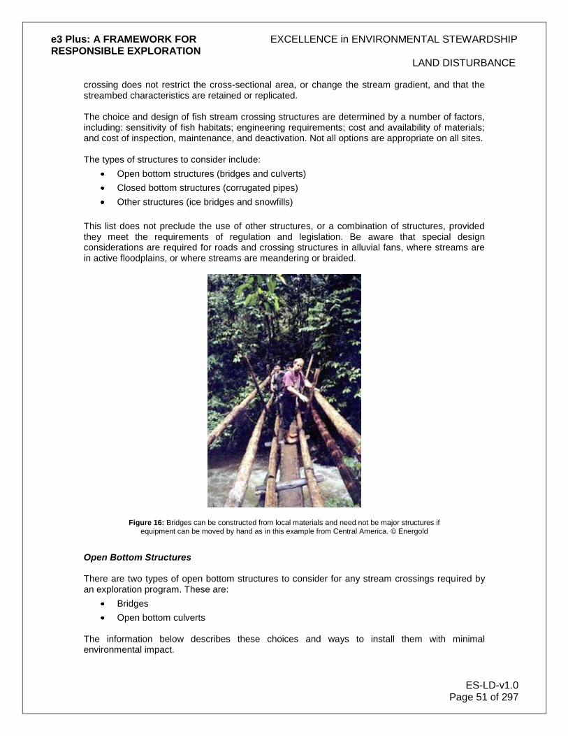
e3 Plus: A FRAMEWORK FOR EXCELLENCE in ENVIRONMENTAL STEWARDSHIP RESPONSIBLE EXPLORATION
LAND DISTURBANCE
ES-LD-v1.0 Page 51 of 297
crossing does not restrict the cross-sectional area, or change the stream gradient, and that the streambed characteristics are retained or replicated. The choice and design of fish stream crossing structures are determined by a number of factors, including: sensitivity of fish habitats; engineering requirements; cost and availability of materials; and cost of inspection, maintenance, and deactivation. Not all options are appropriate on all sites. The types of structures to consider include:
Open bottom structures (bridges and culverts)
Closed bottom structures (corrugated pipes)
Other structures (ice bridges and snowfills)
This list does not preclude the use of other structures, or a combination of structures, provided they meet the requirements of regulation and legislation. Be aware that special design considerations are required for roads and crossing structures in alluvial fans, where streams are in active floodplains, or where streams are meandering or braided.
Figure 16: Bridges can be constructed from local materials and need not be major structures if equipment can be moved by hand as in this example from Central America. © Energold
Open Bottom Structures There are two types of open bottom structures to consider for any stream crossings required by an exploration program. These are:
Bridges
Open bottom culverts The information below describes these choices and ways to install them with minimal environmental impact.

e3 Plus: A FRAMEWORK FOR EXCELLENCE in ENVIRONMENTAL STEWARDSHIP RESPONSIBLE EXPLORATION
LAND DISTURBANCE
ES-LD-v1.0 Page 52 of 297
Bridges When designed and constructed with abutments that do not constrict the stream channel, bridges have the least impact on fish passage and fish habitat. When constructing bridges, get appropriate engineering input to ensure the least impact.
Figure 17: A well-constructed bridge can minimize stream disturbance, carry heavy equipment and need not have high cost. © Golden Band.
Bridges can be designed for permanent, temporary, or seasonal installation. They range from log stringer bridges (with gravel or timber decks) to steel girder bridges (with timber or precast concrete decks). Bridges can be supported by various means, including:
Log cribs
Steel pipes
Steel bin walls
Cast-in-place concrete
Precast lock block walls
Timber
Piers
Where practicable, avoid in-stream piers, because these can collect debris during flood events, resulting in scouring of bridge foundations. In-stream piers can also result in hydrologic changes, such as bedload scour or deposition, which may adversely affect fish habitat. It is likely that fisheries agencies may only approve bridges with support piers after all other options (e.g., clear span) are considered. The decision to use a bridge rather than a culvert can be driven by:
Economics
Engineering requirements
Site parameters
Environmental or hydraulic concerns

e3 Plus: A FRAMEWORK FOR EXCELLENCE in ENVIRONMENTAL STEWARDSHIP RESPONSIBLE EXPLORATION
LAND DISTURBANCE
ES-LD-v1.0 Page 53 of 297
Bedload and debris transport factors Three examples of bridges are:
Steel girder bridge
Log stringer bridge
Concrete slab bridge It should be noted that a well-designed and constructed log stringer bridge can carry most of the heavy loads required for exploration programs, and costs considerably less than a steel girder or concrete slab bridge.
Figure 18: Good example of a steel girder bridge with wooden deck and stone-filled cribs. Locking gate can be used in this case to control access.© Noranda/Falconbridge
Open Bottom Culverts Open bottom culverts are similar to bridge structures, generally spanning the entire streambed and minimizing impacts to the natural stream channel. They are differentiated from bridges in that the fill placed over these structures is an integral structural element.
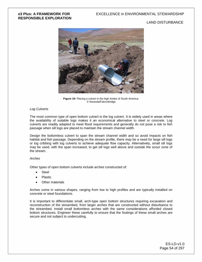
e3 Plus: A FRAMEWORK FOR EXCELLENCE in ENVIRONMENTAL STEWARDSHIP RESPONSIBLE EXPLORATION
LAND DISTURBANCE
ES-LD-v1.0 Page 54 of 297
Figure 19: Placing a culvert in the high Andes of South America. © Noranda/Falconbridge
Log Culverts The most common type of open bottom culvert is the log culvert. It is widely used in areas where the availability of suitable logs makes it an economical alternative to steel or concrete. Log culverts are readily adapted to meet flood requirements and generally do not pose a risk to fish passage when sill logs are placed to maintain the stream channel width. Design the bottomless culvert to span the stream channel width and so avoid impacts on fish habitat and fish passage. Depending on the stream profile, there may be a need for large sill logs or log cribbing with log culverts to achieve adequate flow capacity. Alternatively, small sill logs may be used, with the span increased, to get sill logs well above and outside the scour zone of the stream. Arches
Other types of open bottom culverts include arches constructed of:
Steel
Plastic
Other materials Arches come in various shapes, ranging from low to high profiles and are typically installed on concrete or steel foundations. It is important to differentiate small, arch-type open bottom structures requiring excavation and reconstruction of the streambed, from larger arches that are constructed without disturbance to the streambed. Install small bottomless arches with the same considerations afforded closed bottom structures. Engineer these carefully to ensure that the footings of these small arches are secure and not subject to undercutting.

e3 Plus: A FRAMEWORK FOR EXCELLENCE in ENVIRONMENTAL STEWARDSHIP RESPONSIBLE EXPLORATION
LAND DISTURBANCE
ES-LD-v1.0 Page 55 of 297
Installation of Open Bottom Structures The steps below outline the general installation procedures to follow for open bottom structures as they apply to fish streams. Ensure that excavation and backfilling for footings does not encroach on the stream channel width. Vibrations during Construction Carry out practices such as pile driving and blasting, that result in vibrations potentially harmful to fish or fish eggs during the in-stream work windows. Fish salvage may be required to remove the fish from harm. Sediment Control at Worksite
Where feasible:
Operate all equipment from the top of the stream bank
Isolate the work area from water sources
Contain sediments within the worksite
Pump out sediment-laden water to a settling site during construction and installation Drainage Do not allow road ditches to drain directly into the stream. Instead, divert ditch water into a constructed sump or, where possible, onto stable forested vegetation that can filter sediments before reaching the stream. Ensure that adequate cross drainage is in place before the bridge approach, to minimize water volume directed into approach ditches at bridge sites. To divert runoff from the road surface, consider:
Crowning the surface
Using rolling grades
Employing other practices (e.g., mounds/waterbars) Where cross ditches are used, ensure that they are properly armoured with broken rock at the outlet and along the base. Constricting the Stream Do not allow activities, including the placement of broken rock, to cause any constriction of the stream channel width. Deleterious Materials
To prevent deleterious substances from entering streams, use precautionary measures with materials such as:
New concrete
Grout
Paint
Ditch sediment
Fuel

e3 Plus: A FRAMEWORK FOR EXCELLENCE in ENVIRONMENTAL STEWARDSHIP RESPONSIBLE EXPLORATION
LAND DISTURBANCE
ES-LD-v1.0 Page 56 of 297
Preservatives If using wood preservatives that are toxic to fish, use them in accordance with local guidelines. Seepage Barriers Geotextiles can be used to prevent loss of fines and gravel through seepage along the edges of structures (e.g., abutments, side walls of arches). The fabric, prefabricated seepage barriers, or other cut-off measures (e.g., sandbagging), installed along the edges of the structure near the inlet, are intended to prevent most of the fines and gravel seepage and mitigate potential support fill erosion that can occur here. Geotextiles For gravel-decked bridges or log culverts, use a geotextile filter fabric to fully cover the stringers, or some other measure to prevent road material from entering the stream. Turnouts Construct turnouts at a sufficient distance from the bridge to prevent road material from entering the stream, and to minimize impacts on riparian vegetation. Closed Bottom Structures Closed bottom structures for fish stream crossings are corrugated pipes (metal or plastic) which, embedded to retain stream substrate, provide fish habitat and fish passage. Closed bottom structures are not allowed in critical fish habitat, but are an option for use in small streams with a stream channel width of 2.5 m or less, and at an average stream gradient of 6% or less. Stream Simulation Experience has shown that closed bottom structures can be successfully installed when paying careful consideration to site conditions and structure design parameters. The stream simulation (also known as embedment methodology) requires the selection of a culvert (pipe) of adequate opening to encompass the stream channel width and to emulate the streambed within the culvert, by lining the bottom with representative streambed substrate. Supplement the natural substrate materials with additional larger material to help retain the substrate within the culvert and assist fish passage. By emulating the streambed and stream channel width, the culvert's stream flow characteristics can reflect the natural stream flow characteristics. The use of closed bottom structures in fish streams requires careful design and layout, paying particular attention to fish passage and fish habitat over the lifespan of the structure. Stream Profile Construct a detailed profile of the existing streambed for an extended distance upstream and downstream of the proposed crossing (approximately 50 m each way), and establish benchmarks for elevation and construction control. The objective is to accurately model the streambed profile, to determine the culvert slope, streambed elevations, and streambed conditions. Streams that have bedrock outcrops or little variation in bed elevation generally require shorter profiles.

e3 Plus: A FRAMEWORK FOR EXCELLENCE in ENVIRONMENTAL STEWARDSHIP RESPONSIBLE EXPLORATION
LAND DISTURBANCE
ES-LD-v1.0 Page 57 of 297
Culvert Installation Design and install a closed bottom culvert at the same slope as the stream, retaining the same stream substrate characteristics within it. For migrating fish, this will impose no changes or stress, nor induce any delays at the crossing structure in upstream migration. Substrate transport should move through the culvert naturally, and there should be no sediment buildup upstream or deprivation downstream. The vertical placement of the culvert in relation to the overall stream longitudinal profile is extremely important. The longitudinal profile of the streambed should be used to ensure that the culvert is located at a low point along the streambed. Remember that the culvert is to follow the slope of the streambed. Make special note of any other non-permanent anomalies (e.g., large debris-holding areas), as they may not provide a suitable location for culvert installation. Where practicable, retain the natural meander pattern of a stream. Do not place a closed bottom structure in the bend of a stream, as this leads to bank erosion and debris problems. When this cannot be achieved, relocate the crossing structure or choose another type of crossing structure, such as an open bottom structure. Pipe Size The stream channel width should determine the required culvert diameter or width. Ensure that the width of the replicated or simulated streambed within the culvert is equal to or greater than the stream channel width, to emulate the natural stream and to prevent deposition, scouring, or other damage at the outlet. Factors that help determine appropriate stream channel width are included below. Size a closed bottom structure to accommodate the 100-year return period peak flow after embedment. Carry out this flow determination, and enlarge the pipe if it cannot pass the 100-year peak flow design. Factors in determining the appropriate culvert width include:
Depth of fill
Skew angle of the culvert to the road
Gradient of the culvert
Required road width Design the closed bottom structure properly to avoid letting side slope and backfill material enter the culvert or flow channel. Use broken rock to provide scour protection for materials potentially exposed to erosion. Embedment For circular culverts, the embedment should make up at least 40% of the culvert diameter, or 0.6 m, whichever is greater. For pipe arch or box culverts, embedment depth should be at least 20% of the vertical rise of the arch. To allow for proper embedment, the streambed requires sufficient layers of unconsolidated gravel, sand, cobble, and other sediment lying over the top of the bedrock to allow for proper embedment. If little streambed is available to be excavated, culvert sinking and embedding strategies become impractical.
e3 Plus: A FRAMEWORK FOR EXCELLENCE in ENVIRONMENTAL STEWARDSHIP RESPONSIBLE EXPLORATION
LAND DISTURBANCE
ES-LD-v1.0 Page 58 of 297
Substrate Placement Within the Pipe For successful substrate placement, it is critical to know the type of material found in the natural streambed, and to have a specification for replicating this material. As a general rule, the sizing of material within the culvert should be similar to the size of material in the adjacent natural stream channel. The hydraulic roughness of the culvert bottom is related to the size of bed material. Hydraulic roughness in turn is related to water velocities and water depth inside the culvert. Based on a design specification for gradation, fill the closed bottom structure with substrate material to the natural streambed level, using clean, well-graded material and supplemental material that is equal to, or greater than, the stream channel particle size. Use a heterogeneous mixture of various substrate sizes that contains enough fine material to seal the streambed. Where the streambed is not sealed, subsurface flow may result, creating a barrier to fish passage. It may be necessary to supplement the substrate by washing in sand and gravel to seal the bed. Wash the simulated streambed and intercept the sediment at the outlet of the pipe before it enters the stream. When closed bottom structures are installed in streams with gradients between 3-6%, the physical placement of supplemental larger material (D90+) is even more important. (Note: D90 is defined as the largest size class of streambed substrate that can be moved by flowing water. Approximately 90% of the streambed substrate will be smaller than this size class.) Oversized material may be problematic, creating increased hydraulic roughness and flushing out fines through the poor gradation of the embedment materials. At these gradients, ensure the pipe is large enough to allow for the physical placement and orientation of these larger elements. This should assist in retaining substrate and preventing scour in the culvert. The design should note the dimensions and quantity of the additional larger material. Establish a thalweg (low-flow channel) through the culvert to enable fish passage at low flow. Closed bottom structures for fish stream crossings are corrugated pipes (metal or plastic) which, embedded to retain stream substrate, provide fish habitat and fish passage. Closed bottom structures are not allowed in critical fish habitat, but are an option to use in small streams with a stream channel width of 2.5 m or less, and at an average stream gradient of 6% or less. Stream Simulation Experience has shown that closed bottom structures can be successfully installed when paying careful consideration to site conditions and structure design parameters. The stream simulation (also known as embedment methodology) requires the selection of a culvert (pipe) of adequate opening to encompass the stream channel width, and emulate the streambed within the culvert by lining the bottom with representative streambed substrate. Supplement the natural substrate materials with additional larger material to help retain the substrate within the culvert and assist fish passage. By emulating the streambed and stream channel width, the culvert's stream flow characteristics can reflect the natural stream flow characteristics. The use of closed bottom structures in fish streams requires careful design and layout, paying particular attention to fish passage and fish habitat over the lifespan of the structure. Stream Profile Construct a detailed profile of the existing streambed for an extended distance upstream and downstream of the proposed crossing (approximately 50 m each way), and establish benchmarks for elevation and construction control. The objective is to accurately model the streambed profile,

e3 Plus: A FRAMEWORK FOR EXCELLENCE in ENVIRONMENTAL STEWARDSHIP RESPONSIBLE EXPLORATION
LAND DISTURBANCE
ES-LD-v1.0 Page 59 of 297
to determine the culvert slope, streambed elevations, and streambed conditions. Streams that have bedrock outcrops or little variation in bed elevation generally require shorter profiles. Culvert Installation Design and install a closed bottom culvert at the same slope as the stream, retaining the same stream substrate characteristics within it. For migrating fish, this will impose no changes or stress, nor induce any delays at the crossing structure in upstream migration. Substrate transport should move through the culvert naturally, and there should be no sediment buildup upstream or deprivation downstream. The vertical placement of the culvert in relation to the overall stream longitudinal profile is extremely important. The longitudinal profile of the streambed should be used to ensure the culvert is located at a low point along the streambed. Remember that the culvert is to follow the slope of the streambed. Make special note of any other non-permanent anomalies (e.g., large debris-holding areas), as they may not provide a suitable location for culvert installation. Where practicable, retain the natural meander pattern of a stream. Do not place a closed bottom structure in the bend of a stream, as this leads to bank erosion and debris problems. When this cannot be achieved, relocate the crossing structure or choose another type of crossing structure, such as an open bottom structure. Installation of Closed Bottom Structures The steps below outline the general procedures to follow for the installation of closed bottom structures in fish streams. Planning Deliver all required materials and mobilize equipment in advance, so the installation can proceed without delay on a dry bed, within the timing window. Employ appropriate worksite isolation techniques during the closed bottom structure installation. Survey Lay out the worksite with precise instruments, including establishing the horizontal and vertical field references, to accurately establish the culvert embedment elevation and slope during construction. Bed Preparation Prepare and grade the culvert bed to conform to the design elevation and slope, using benchmarks and precise instruments. Ensure the barrel of the closed bottom structure is set to the appropriate depth below the streambed, and at the same natural stream gradient as shown by the longitudinal profile survey. Ensure that the culvert foundation, trench walls, and backfill are free of logs, stumps, limbs or rocks that could damage or weaken the pipe. Seepage Barriers Consider using geotextiles to prevent loss of fines and gravel through seepage along the culvert wall. The fabric, or other cut-off measure (e.g., sandbagging, prefabricated seepage barriers), placed along the culvert near the inlet, is intended to cut off most seepage and mitigate potential support fill erosion that can occur along the pipe.

e3 Plus: A FRAMEWORK FOR EXCELLENCE in ENVIRONMENTAL STEWARDSHIP RESPONSIBLE EXPLORATION
LAND DISTURBANCE
ES-LD-v1.0 Page 60 of 297
Drainage Do not allow side ditches to drain directly into the stream. Instead, divert ditchwater into a constructed sump or, where possible, onto stable forested vegetation that can filter sediments before the water reaches the stream. Ensure that adequate cross drainage is in place before the culvert approach, to minimize the water volume directed into approach ditches at culvert sites. Consider the use of mounds (waterbars) to divert road surface runoff. Where cross ditches are used, ensure that they are properly armoured with broken rock at the outlet and along the base. Constricting the Stream Do not allow any activities, including the placement of broken rock, to cause any constriction of the stream channel width. Erosion Protection Begin erosion-proofing all exposed mineral soil as soon as possible after disturbance. Downstream Weir Establish an in-stream weir within 1.5 to 2 channel widths downstream of the culvert outlet, particularly for streams greater than 3% gradient, to retain substrate within the culvert and to prevent the formation of a plunge pool. The residual pool depth formed by this downstream weir should be less than 0.3 m. Backfill Your backfill practices should conform to those specified by the culvert manufacturer, or otherwise specified by an engineer, and incorporate mechanical vibratory compaction immediately adjacent to the culvert. Slopes >3% grade For culverts installed at slopes greater than 3%, you should mix larger material (D90 or greater) into the substrate to help retain the substrate in the pipe. You should place the larger material so that it projects from the streambed. This should create velocity shadows to enhance fish passage, retain substrate, and simulate conditions in the natural stream. Ice Bridges Ice bridges are effective stream-crossing structures in cold climates for larger streams and rivers, where the water depth and stream flow under the ice are sufficient to prevent the structure from coming in contact with the stream bottom (grounding), and where there are no concerns regarding spring ice jams. Grounding can block stream flow and fish passage and cause scouring of the stream channel. Design of Ice Bridges
Consider the following when planning the design of ice bridges:
Depth of water
Minimum winter daily stream flow
Substrate
Crossing location

e3 Plus: A FRAMEWORK FOR EXCELLENCE in ENVIRONMENTAL STEWARDSHIP RESPONSIBLE EXPLORATION
LAND DISTURBANCE
ES-LD-v1.0 Page 61 of 297
Maximum load strength
Time of use
Thickness of ice required
Approach construction
Maintenance and monitoring
Decommissioning Installation of Ice Bridges The steps below outline the general installation procedures for ice bridges as they apply to fish streams:
Determine whether using logs as reinforcing material could cause problems. There is a possibility that logs, if left in place through spring break-up, could contribute to debris jams and increase the risk of flooding, river channel alteration, erosion, and habitat loss. If this is an unacceptable risk, do not use logs. In most cases, log removal from a deteriorating ice bridge is an unsafe practice. In these situations, removing all but the lowest logs from the ice bridge may be acceptable.
Measure and record ice thickness and stream depth routinely. Evidence of grounding, or an increased risk of the ice base grounding with the streambed, may require that the bridge be temporarily or permanently decommissioned.
Locate ice bridges where cutting into the stream bank would be minimized during construction of the approaches. Remove all debris and dirt and place this at a stable location above the high-water mark of the stream.
Construct approaches of clean compacted snow and ice to an adequate thickness to protect stream banks and riparian vegetation. Construction should begin from the ice surface. Where limited snow is available, gravel (if available locally and from approved pits) can be used to build up approaches. Remove this gravel when the ice bridge is deactivated.
When it is time for deactivation, remove all ice bridge approaches. Recontour and revegetate stream banks where the soil has been exposed, using all appropriate measures to stabilize the site and facilitate its return to a vegetated state.
Snowfills Snowfills are options to consider for seasonal use, depending on the site, time of year, and other environmental constraints that may apply. Construct and deactivate snowfills such that they do not affect fish or fish habitat at break-up. Deactivation is difficult and often results in channel disturbance as frozen material clings to logs. Construct snowfills by filling the channel with compacted clean snow (e.g., free of dirt and debris). Consider their use only if the stream is dry or the water is frozen to the stream bottom. Log bundles or culverts can accommodate unanticipated stream flow due to unseasonal thaws. To avoid adverse impact on the stream, remove the log bundles, culverts, and snow prior to spring thaw.
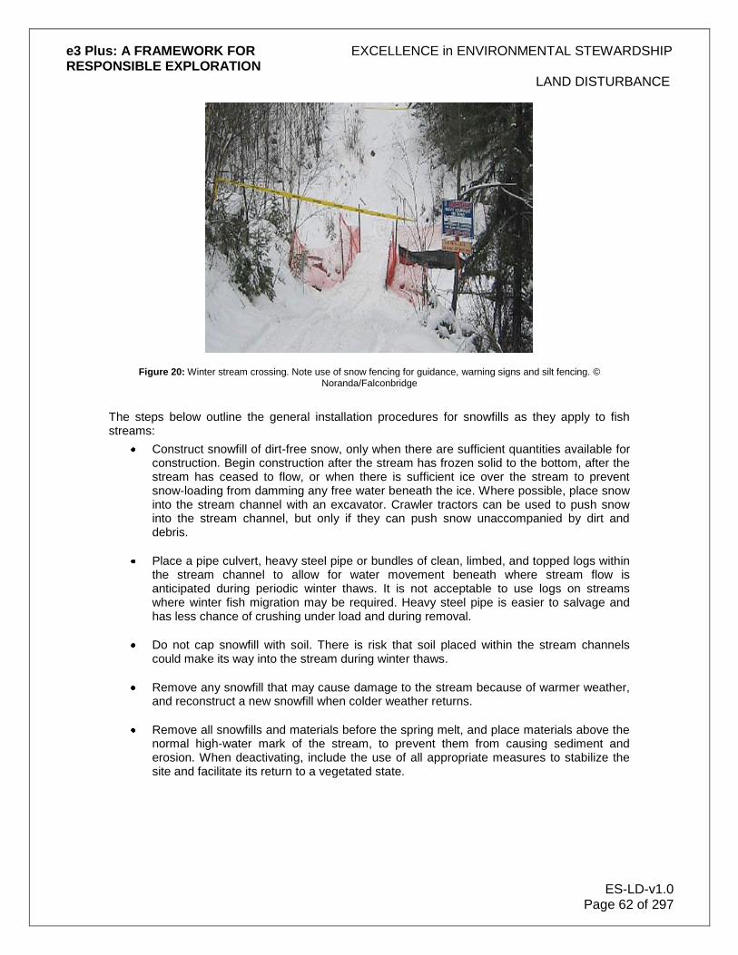
e3 Plus: A FRAMEWORK FOR EXCELLENCE in ENVIRONMENTAL STEWARDSHIP RESPONSIBLE EXPLORATION
LAND DISTURBANCE
ES-LD-v1.0 Page 62 of 297
Figure 20: Winter stream crossing. Note use of snow fencing for guidance, warning signs and silt fencing. © Noranda/Falconbridge
The steps below outline the general installation procedures for snowfills as they apply to fish streams:
Construct snowfill of dirt-free snow, only when there are sufficient quantities available for construction. Begin construction after the stream has frozen solid to the bottom, after the stream has ceased to flow, or when there is sufficient ice over the stream to prevent snow-loading from damming any free water beneath the ice. Where possible, place snow into the stream channel with an excavator. Crawler tractors can be used to push snow into the stream channel, but only if they can push snow unaccompanied by dirt and debris.
Place a pipe culvert, heavy steel pipe or bundles of clean, limbed, and topped logs within the stream channel to allow for water movement beneath where stream flow is anticipated during periodic winter thaws. It is not acceptable to use logs on streams where winter fish migration may be required. Heavy steel pipe is easier to salvage and has less chance of crushing under load and during removal.
Do not cap snowfill with soil. There is risk that soil placed within the stream channels could make its way into the stream during winter thaws.
Remove any snowfill that may cause damage to the stream because of warmer weather, and reconstruct a new snowfill when colder weather returns.
Remove all snowfills and materials before the spring melt, and place materials above the normal high-water mark of the stream, to prevent them from causing sediment and erosion. When deactivating, include the use of all appropriate measures to stabilize the site and facilitate its return to a vegetated state.

e3 Plus: A FRAMEWORK FOR EXCELLENCE in ENVIRONMENTAL STEWARDSHIP RESPONSIBLE EXPLORATION
LAND DISTURBANCE
ES-LD-v1.0 Page 63 of 297
Fords
Fords, constructed as crossing structures, can result in habitat degradation through sedimentation, channel compaction, and the creation of barriers to fish passage. For these reasons, authorizing agencies do not encourage the construction of fords on fish streams. If considering a ford, check with the appropriate fisheries agency. The fording of fish streams is generally limited to one location and one crossing (over and back) for each piece of equipment required for construction on the opposite side. Where additional movements of equipment may be required, obtain approval from the appropriate fisheries agency, regardless of habitat type. Use a temporary crossing, or other practices, to protect the streambed and banks, if the streambed and stream banks are highly erodible (e.g., dominated by organic materials, silts, silt loams), and significant erosion and stream sedimentation or bank or stream channel degradation may result from heavy equipment crossings.
5.6 Controlling Sediment
It is important to contain sediment-laden runoff so that soil particles can be removed using filtering or settling methods. Control sediment at the source, as much as possible. Once entrained in water, it is more difficult to control. To effectively control sediment during excavation or construction, use the following, singularly or in combination:
Sediment traps and basins
Silt fences
Straw bale dikes and basins
Geotextiles Sediment traps and basins can be either simple, small pits or large, complex, engineered structures designed to impound large quantities of sediment. Silt fences and straw bales, in contrast, are designed primarily to intercept and filter small volumes of sheet-flowing, sediment-laden runoff, before it reaches the watercourse. These are more likely to be applicable to exploration programs. Do not use silt fences as filters within a watercourse, as they have limited capacity to pass water. On completion of the exploration activity, remove these temporary control structures and stabilize the sediment. It is important to control runoff and remove sediment from diverted drainages. The variety of methods that can be used include:
Barriers
Traps
Settling ponds These methods slow the flow of water and allow the suspended sediment to settle or be trapped in filters. The type of barrier to choose depends on the:
Materials available

e3 Plus: A FRAMEWORK FOR EXCELLENCE in ENVIRONMENTAL STEWARDSHIP RESPONSIBLE EXPLORATION
LAND DISTURBANCE
ES-LD-v1.0 Page 64 of 297
Drainage configuration
Particle size of suspended sediment
Velocity of runoff
Site layout Types of barriers include:
Straw bales and sandbags, incorporating geotextile filter cloth
Silt fences
Brush barriers
Diversions and dams
Sediment traps or basins These barriers and/or traps can temporarily control sediment at sites with low volumes of water and sediment. Barriers can be placed across ditches or drainages at periodic intervals, on the perimeter of a disturbed area and at storm drain inlets. Traps and basins also can filter out sediment effectively.
5.6.1 Straw Bales and Sandbags
Straw bales and sandbags are best suited where temporary, relatively minor erosion control is needed, while more permanent solutions are being devised. However, do not use sandbags as filters within a watercourse, as they have limited capacity to pass water. When used properly, straw bales can be effective in intercepting sheet flow runoff at the base of a slope, or in acting as a check-dam in the ditchline of a road. Do not stack straw bales on top of each other. Take care to ensure that noxious weeds and non-native grasses are not spread as a result of using straw bales. In particular, hay bales generally contain the edible portion of grasses and more seeds than straw bales. Straw bales and sandbags require routine inspections, maintenance and frequent repair, particularly after precipitation. In order to extend their effective service life when installing these barriers:
Use straw bales bound with wire or nylon line (less susceptible to rot).
Excavate a trench the width of the bales and to a depth of 15 cm.
Lay the straw bales on their sides and stake in place. At a minimum, drive 2 metal stakes through each bale, and extend into the ground at least 30 cm. Angle the first stake toward the previously placed bale, and drive through both the first and second bale.
Tamp and smooth any excavated soil along the upstream portion of the barrier.
Incorporate geotextile fabric with straw bale barriers, or use them in conjunction with a silt fence, to improve their effectiveness. In some circumstances, straw bales can be used to help anchor silt fencing To ensure that straw bale or sandbag barriers remain effective:
Remove deposited sediment routinely and dispose off-site
Replace damaged or rotten bales or sandbags

e3 Plus: A FRAMEWORK FOR EXCELLENCE in ENVIRONMENTAL STEWARDSHIP RESPONSIBLE EXPLORATION
LAND DISTURBANCE
ES-LD-v1.0 Page 65 of 297
Figure 21: Used together, silt fencing and hay bales can be very effective in some circumstances. © Noranda/Falconbridge.
5.6.2 Silt Fences
Filter or silt fences are designed to intercept surface runoff on slopes of varying degree. They retain soil on the site and reduce runoff velocity across areas below the fence. Silt fences are effective, and can be used to intercept soil from disturbed slopes and ditchlines, and to isolate work areas from a stream. They are intended to prevent sediment from entering channelized flows. Construct these barriers in series, depending on the size of the contributing drainage area. A rule of thumb is approximately 30 m of fence for every 0.1 ha of drainage area. Fences require regular maintenance to maintain functionality, so access is necessary. Construction of filter or silt fences involves attaching filter fabric to wood stakes. Depending upon the specifics of the site, place the stakes on 1-2 m centres. Construct a trench along the base of the silt fence and ensure that approximately 20 cm of the filter fabric (a suitable permeable geotextile) is buried both vertically and horizontally, to hold the fabric in place. After securely attaching the filter fabric on the uphill side of the wood stakes, backfill the trench and compact the soil against the filter fabric. The average usable life of filter or silt fences is 6 months to 1 year. Thoroughly inspect the filter or silt fence after each precipitation or storm event, and immediately repair it if required. Remove sediment regularly to keep the barrier functional, and do not allow sediment to reach one-half the height of the fence. Properly dispose of excavated material off-site and never place it downslope. The effectiveness of filter or silt fences is excellent if they are installed properly and maintained regularly. After work is completed, carefully remove silt fence structures, to prevent the sediment retained from entering the watercourse or being remobilized during the next precipitation or storm event.

e3 Plus: A FRAMEWORK FOR EXCELLENCE in ENVIRONMENTAL STEWARDSHIP RESPONSIBLE EXPLORATION
LAND DISTURBANCE
ES-LD-v1.0 Page 66 of 297
Figure 22: Silt fence in place on stream crossing in northern Canada. © Noranda/Falconbridge.
5.6.3 Brush Barriers
Brush barriers are perimeter sediment control structures that you can use to prevent soil in storm water runoff from leaving a construction site. Brush barriers are constructed of material such as small tree branches, root mats, stone, or other debris left over from site clearing and grubbing. In some configurations, you can cover brush barriers with a filter cloth to stabilize the structure and improve barrier efficiency.
Generally, the drainage slope leading down to a brush barrier should be no greater than 2:1 and no longer than 30 metres. You should recognize that brush barriers have limited usefulness because they are constructed of materials that decompose.
You should construct a brush barrier using only material cleared from a site, and you can cover the mound of material with a filter fabric barrier to hold the material in place and increase sediment barrier efficiency. Whether a filter fabric cover is used or not, the barrier mound should be at least 1 metre high and 1.5 metres wide at its base. You should not use material with a diameter larger than 15 centimetres, as it may be too bulky and create void spaces where sediment and runoff will flow through the barrier.
You should bury the edge of the filter fabric cover in a trench 10 centimetres deep and 15 centimetres wide on the drainage side of the barrier in order to secure the fabric and create a barrier to sediment while allowing storm water to pass through the water-permeable filter fabric. The filter fabric should be extended just over the peak of the brush mound and secured on the down-slope edge of the fabric by fastening it to twine or small-diameter rope that is staked securely.
Brush barriers are an effective storm water runoff control only when the contributing flow has a slow velocity and are therefore not appropriate for high-velocity flow areas. A large amount of material is needed to construct a useful brush barrier. For sites with little material from clearing, you may find that alternative perimeter controls such as a fabric silt fence may be more appropriate. Although brush barriers provide temporary storage for large amounts of cleared

e3 Plus: A FRAMEWORK FOR EXCELLENCE in ENVIRONMENTAL STEWARDSHIP RESPONSIBLE EXPLORATION
LAND DISTURBANCE
ES-LD-v1.0 Page 67 of 297
material from a site, you will have to remove this material from the site after construction activities have ceased and the area reaches final stabilization.
You should inspect brush barriers after each significant rainfall event to ensure continued effectiveness. If channels form through void spaces in the barrier, you should reconstruct the barrier to eliminate the channels. You should remove accumulated sediment from the uphill side of the barrier when sediment height reaches between 1/3 and 1/2 the height of the barrier. When the entire site has reached final stabilization, you should remove the brush barrier and dispose of it properly.
5.6.4 Diversions and Dams
Sediment delivered to stream channels can harm fish and fish habitat. Most sedimentation occurs in the first year, when soils are exposed during and immediately following road construction or stripping. The amount of sediment generated at a stream crossing or from a construction or excavation site is directly related to the:
Sensitivity of the soil to erosion
Amount of area exposed to runoff or stream flow
Disturbance caused by the camp or road construction Diversions and dams redirect water away from disturbed sites or create "dry" work areas in streams, thereby minimizing the erosional effects of flowing water. It is essential to prevent sedimentation by minimizing disturbance to stream banks and retaining riparian vegetation. Many small streams and adjacent worksites are dry during the dry season, allowing construction or excavation without special measures for erosion and sediment control. When water is present, most erosion and sediment problems can be avoided through the use of a variety of methods that control sediment at the source, and prevent it from becoming entrained in the flowing water. The key is to isolate flowing water from the worksite. During periods of heavy or persistent rainfall:
Suspend work activities, as they could result in sediment delivery to the stream and adversely affect aquatic resources
Implement measures to minimize the risk of sediment delivery to the stream The subsections which follow present details of
Diversions
Cofferdams Diversions It may be necessary for you to divert uncontrolled surface water runoff from around disturbed surfaces in order to minimize erosion (such as sheet wash and gullying). Where necessary, you should construct storm water runoff drainage systems and adapt them to the general terrain of the area. Before the start of construction, excavation or road building activities you should construct drainage diversions to
Intercept water, and
e3 Plus: A FRAMEWORK FOR EXCELLENCE in ENVIRONMENTAL STEWARDSHIP RESPONSIBLE EXPLORATION
LAND DISTURBANCE
ES-LD-v1.0 Page 68 of 297
Divert it away from work areas. To provide adequate drainage and slope gradient to control the volume and velocity of runoff you can use
Sloping,
Ditching, and
Berming. It is generally better for you to spread out water than to concentrate it. In order to collect and divert runoff, you should
Locate cleared areas on the most level ground available.
Avoid areas subject to flooding.
Design construction or stripping so as to avoid creating long uninterrupted slopes.
Create sloping or crowning road surfaces to prevent water from collecting and flowing along the road.
You should also
Develop a system of ditches and culverts for permanent or heavily used roads. On temporary roads, you can use waterbars (mounds) and dips (narrow, shallow trenches) to divert water, and these should be installed at frequent intervals to prevent concentrating runoff (see figure below). You should construct waterbars at an angle across the road to permit downhill drainage of water across the road or track.
Control any discharge of diverted water.
Plan roads, grids, and trenching with as low a grade as possible. Maximum grades of 8 to 10 percent are desirable, although short distances of 15 percent can be accepted if necessary.
You should place rip-rap, as needed, in locations where the soil is easily erodible. You can provide sediment control structures such as silt fences or rip-rap in camp runoff gullies before their intersection with natural systems. You should place rip-rap or a shot rock pad at the outlet of all cross drains where ditch water is being diverted from an approach ditchline and discharged onto erodible soils or fills. You will find that ditches lined with rip-rap, shot rock, or large gravel are an effective method for reducing erosion at approaches to stream crossings. Rip-rap slows the velocity of ditch water and armours erodible ditch bed materials. All rip-rap or rock that you use should be free of
Silt.
Overburden.
Debris.
Other substances deleterious to fish. The material should be durable and sized to resist movement by streamflow. Where rip-rap is not available, you can use fabric linings temporarily at approaches and culvert spillways.

e3 Plus: A FRAMEWORK FOR EXCELLENCE in ENVIRONMENTAL STEWARDSHIP RESPONSIBLE EXPLORATION
LAND DISTURBANCE
ES-LD-v1.0 Page 69 of 297
On small streams or where flows are very low, pipes or erosion-proofed ditches may be adequate to divert flow around the construction site. To minimize sediment loss at these sites from and along the diversion, you should install sediment traps, combined with the use of geotextiles. You should always excavate temporary stream diversions in isolation from streamflow, starting from the bottom end of the diversion channel and working upstream to minimize sediment production. To prevent loss of sediment, you should leave the bottom end of the diversion channel intact until the diversion trench is almost complete and you should not open it until all measures have been taken to reduce surface erosion resulting from water flowing in the new channel. After your exploration activity has been completed, you should close the diversion from the upstream end first and re-establish the pre-diversion conditions, stabilize and revegetate the site. Where practical, you can also pump water across the work site and discharge it into the stream channel below the site. This technique requires that you dam the stream above the exploration site. This eliminates the need for a diversion channel, and thus greatly reduces the problems of sediment production associated with digging and operating a newly created stream channel. You should screen pump intakes to prevent entrainment of juvenile fish. Backup pumps on site are highly recommended in all pumping situations. Cofferdams You may require cofferdams to isolate work from the streamflow. Cofferdams are temporary enclosures that are built in the stream bed to keep water out during the construction activity. When building these structures you should not reduce the stream channel width by an amount that could lead to erosion of the opposite banks or of upstream and downstream areas. You can construct cofferdams in various ways. For example, sandbags lined with geotextiles or rubber aqua dams can be used. You should remove all materials after your exploration activity is completed, and discharge all water pumped from contained work areas within cofferdams to a forested site to allow sediment to settle before the water re-enters the stream. Dams can experience the buildup of sediment. You should be aware that
Water retention or siltation ponds (or sediment ponds) collect runoff and allow the suspended sediment to naturally settle to the bottom of the pond.
Dams and embankments can be constructed and shaped to reduce the runoff velocities.
Sedimentary basins may be required to control the discharge of suspended solids which will settle out of the water when it is left standing in the basin for a period of time.
5.6.5 Sediment Traps or Basins
Sediment traps or basins are excavated pits that capture coarse sediments from ditchlines before they can enter a stream. For these to be effective, clean all sediment traps and basins frequently while they are in place. At the site of a stream crossing, direct ditch water into the sediment trap or basin. If a large amount of ground water is encountered, or anticipated, during drilling or trenching operations, construct a sediment basin (mud pit). Constructed properly, sediment basins reduce or abate water pollution, by providing basins for deposition and storage of silt, sand, gravel, stone, drill cuttings, and other debris.

e3 Plus: A FRAMEWORK FOR EXCELLENCE in ENVIRONMENTAL STEWARDSHIP RESPONSIBLE EXPLORATION
LAND DISTURBANCE
ES-LD-v1.0 Page 70 of 297
Sediment basins can be utilized in conjunction with erosion control measures installed at the source of the sediment, or where a sediment basin offers the most practical solution to the problem. Straw bales and filter fences work effectively with sediment basins.
5.7 Special Terrains
Some terrains may have unique ecologies that are particularly sensitive to land disturbance. It is important to recognize the vulnerabilities of these terrains, and to operate around them to minimize any impact. The following sections discuss specific terrains, and the measures that are applicable to them.
5.7.1 Arctic and Alpine Terrains
Arctic and alpine terrains are typically very fragile and highly sensitive to change. These regions have very slow growth rates and any disturbance can be very long lasting. If at all possible, avoid road construction in such areas. Tracks are difficult to construct and nearly impossible to restore. It is preferable to use tracked, low ground pressure vehicles when there is adequate snow cover, or helicopters. To minimize loss of topsoil in alpine terrains, preserve the vegetation cover as far as possible. If a road must be constructed for transport of equipment and supplies in arctic terrains, use a winter road. Use only clean snow and ice as fill material, minimizing the damage to the fragile arctic environment, as the ground will be frozen. Make sure that the route is marked, confining traffic to the selected route and preventing vehicles from becoming lost during whiteout conditions. Arctic Terrain For purposes of EES Plus, the Arctic is considered that portion of the northern hemisphere generally above the tree line. As such, the Arctic includes portions of North America, Asia and Europe. The region is characterized by long winters with short daylight periods and short but dynamic summer periods. Permafrost is ubiquitous. Precipitation is low and much of the Arctic is a true desert despite the presence in portions of the region of almost continuous snow and ice cover. Parts of the Arctic encompass alpine terrain, coastal terrain, wetlands and riparian terrain. Population is generally sparse and dominantly made up of indigenous peoples. Vegetation and wildlife are unique, in largest part due to the climate and but also due to lack of human activity in the area. The low precipitation and generally low temperatures create conditions where material left in the field can last for generations and damage to soils/vegetation can take many years to heal. This unique and valuable environment requires special respect and attention during exploration programs. Exploration in the Arctic requires special planning to avoid unnecessary environmental impact. Wherever possible, plan programs during the winter season to avoid impact on fragile vegetation and soil cover. (Clearly, this is not possible for prospecting and mapping programs but these activities are much less disruptive.) Avoid all activities that might disrupt the migratory pattern of animal life (information on migration patterns and periods is usually available from local wildlife officials.) Respect cultural and archaeological sites (see separate EES Plus section.) Ensure that only native species are used for reclamation purposes. Almost all Arctic exploration involves fuel handling and containment to one degree or another. Fuel caches are usually required because of the long distances from supply centres to the project. All the precautions described elsewhere on this website apply but it should be especially

e3 Plus: A FRAMEWORK FOR EXCELLENCE in ENVIRONMENTAL STEWARDSHIP RESPONSIBLE EXPLORATION
LAND DISTURBANCE
ES-LD-v1.0 Page 71 of 297
noted that fuel leaks often go unnoticed with snow cover since the fuel will travel beneath the snow. Cleanup of such leaks is difficult and messy. The best solution is prevention of all leaks. Permafrost conditions are unique to the Arctic and certain alpine terrain. Special care is needed when working in such conditions to avoid uncontrolled thawing of the permafrost. Exposure of the permafrost during warmer seasons will create melt which becomes self-perpetuating, i.e. the meltwater itself causes thawing of more and more permafrost. Especially in areas of slope, this melting will create gullys and unsightly erosional scars on the landscape.
Figure 23: Drilling in the Arctic may require special techniques to deal with permafrost (and the long hours without sunlight). © BHPBilliton.
Wherever possible, use helicopter (or fixed wing) access and servicing for all programs in Arctic terrain. (In most cases, this will be the most effective means of access for other reasons as well.) If other forms of access are required, use lightweight, low ground pressure vehicles and, wherever possible, restrict their use to snow and ice covered areas. Avoid disturbance of permafrost, vegetation and soil. Objects and landscape scars are visible for many kilometres in the Arctic both from the air and on land. Because of climatic conditions, decay of these objects and healing of the scars are extremely slow. As explorationists we must act responsibly to avoid such situations. We will become (with justification) more obvious targets for activist groups if we are the cause of such problems. Trenching and pitting in the Arctic should be reclaimed as soon as possible, especially in permafrost areas. Particularly if on a slope, the trench will become an unsightly point source of erosion by rain and meltwater. Organic soil should be carefully preserved for use during reclamation. Trenches and pits in permafrost for placer gold exploration require special mention. Side slopes in ice-rich overburden ("black muck") may be left near-vertical to thaw and stabilize naturally. Ideally, these slopes should be undercut so that the top vegetated mat falls over and covers the exposed ice-rich slope. As in all trenching or pitting programs, special care should be taken to ensure trenches and open cuts for placer exploration do not become self-perpetuating growing gullies.

e3 Plus: A FRAMEWORK FOR EXCELLENCE in ENVIRONMENTAL STEWARDSHIP RESPONSIBLE EXPLORATION
LAND DISTURBANCE
ES-LD-v1.0 Page 72 of 297
Alpine Terrain Definition Alpine terrain is steep-sloped landscape occurring above the tree line in mountainous country, covered with grass, scree/talus, and rock. Although the word “alpine” (derived from the Alps of Europe) is used in this section, in South America a more appropriate word would be “andean” (derived from the Andes Range). Some of the descriptions also apply to tundra terrain, although differences in sunlight intensity, variation between daytime and nighttime temperatures and other factors lead to important distinctions between alpine and tundra conditions. Tundra is mainly restricted to circum-Arctic regions, largely in the northernmost parts of North America and Eurasia, together with the coast of Greenland and a number of Arctic islands. For the sake of brevity, this section will use only the word “alpine”. Alpine terrain occurs at all latitudes – even at the equator – as the tree line occurs at any elevation that fails to have 60 days with temperatures of more than 15°C. At altitudes with these conditions, there is no sustained tree growth, so there is no continuous cover of deciduous and/or coniferous trees. Alpine terrain is found throughout an extremely wide range of climatic zones, descending from elevations of 4,000-5,000 m.a.s.l. in the warm and cool temperature mountainous regions, through to sea level in the sub-Artic/sub-Antarctic regions. Examples of these wide-ranging climatic zones include:
Hot/wet: the Andes (Brazilian slope), Central America, Ruwenzori (Congo/Uganda), Himalayas, Irian Jaya (Indonesia), Philippines, Borneo, Papua New Guinea.
Hot/dry: Interior Andes, Iran, Pakistan, south-central Asia.
Temperate/wet: Tasmania, New Zealand, northern Europe, coastal British Columbia, northwest United States, Japan.
Temperate/dry: Nevada, Colorado, California, central interior British Columbia, central Argentina.
Cold/wet: Northern coastal British Columbia, coastal Alaska, south-central Chile, Patagonia, northern coastal Scandinavia.
Cold/dry: Interior Yukon, Greenland, Spitsbergen, Argentinean Patagonia, sub-Antarctica, interior Alaska, Urals, Siberia, north-central Asia.
Alpine terrains have a high percentage of rock exposure, and give prospectors the ability to locate distinctive colour anomalies due to alteration and gossans. Alpine terrains also make it possible, with relative ease, to carry out heavy mineral, silt, soil, and rock geochemistry, and to relate any geochemical anomalies to a specific location. However, the terrain that provides these positive attributes is one of the most fragile and highly vulnerable to any disturbance caused by mineral exploration activity. Potential Impacts on Alpine Terrains In the low temperature environment of the alpine terrain there is little biological activity of any kind, with little possibility of biological regrowth to mitigate any disturbance. This terrain records every intrusion that is made on it and the visual reminders of these intrusions can last for hundreds of years. As tracings of exploration activity often have a striking linearity (e.g.,

e3 Plus: A FRAMEWORK FOR EXCELLENCE in ENVIRONMENTAL STEWARDSHIP RESPONSIBLE EXPLORATION
LAND DISTURBANCE
ES-LD-v1.0 Page 73 of 297
geochemical and geophysical survey lines), they are immediately and jarringly obvious to the eye against the natural harmonious background. Without tree cover, every object is extremely visible, often from tens of kilometers and even in areas which experience torrential rain, mass wasting, soil creep, cryoturbation.
1 For example, an
orange peel might be very visible throughout the many years it takes to decay. This is also true for any man-made addition to the alpine landscape, from toilet paper, cans, wooden pickets, nylon measuring thread, and other objects used when laying out survey lines. Coloured flagging tape will last for decades, but the intense ultraviolet radiation is likely to turn all colours to white and marker pen numbers can begin to deteriorate within one or two summers. Exploration programs in alpine terrains have the potential to have an impact on more than just the surface. In permafrost areas, a different set of impacts can have serious consequences. This is especially the case on polar-facing slopes, where permafrost is often at surface or within centimeters of the surface. Any disruption of the surface will lead to almost immediate melting of the permafrost, with quite extreme consequences. Firstly, erosion “gullying” will begin on side hills; this gullying becomes self-perpetuating. Secondly, some of these permafrost areas, particularly in the high Arctic, are effectively “cold deserts”; the unique supply of surface water from the exposed permafrost can cause greatly enhanced biological activity. This results in, for example, a path/road becoming a vivid linear array of alder bush against the local subdued grass/willow scrub. Much of northern Scandinavia, Siberia, Alaska, Yukon, mountainous Northwest Territories, Nunavut, northern Quebec and southernmost Chile and Argentina lies within the semi-permanent/permanent permafrost zone. On equator-facing slopes where the permafrost lies at greater depth (+/- 1 m), there is not the same degree of gullying or biological stimulation when the surface is broken; instead, a linear brown scar can remain for literally hundreds of years. Also, as there is always some water (rain/snow/permafrost) available, erosion of a disturbed site can continue indefinitely. In fact, a surface disturbance becomes the locus for a new drainage system which usually intersects existing drainages, making these hydraulically unstable, unsightly and highly visible. Best Practice Guidelines – Above the Tree Line The best solution to any of the above problems is prevention rather than remediation.Mineral exploration in alpine terrain has to be carried out with the absolute minimum degree of physical impact, even at the earliest stages, including:
Reconnaissance exploration (e.g., staking, widespread regional sampling, or ground geophysics)
Establishing grid lines
Soil/stream sampling with station positions
Hand-dug pits If possible, there should be no roads to campsites and drill sites. Instead, helicopters should be used to transport people and equipment, using the smallest sized helicopter pads, or float/ski planes should be employed on lakes or snow whenever possible.
1 For a list of terminology see http://nsidc.org/fgdc/glossary/english.html#C
e3 Plus: A FRAMEWORK FOR EXCELLENCE in ENVIRONMENTAL STEWARDSHIP RESPONSIBLE EXPLORATION
LAND DISTURBANCE
ES-LD-v1.0 Page 74 of 297
The following considerations are critical when working in alpine terrains:
1. Campsites When selecting a campsite location, ask the following pertinent questions
2:
Will it be on level ground and well drained?
Will it be situated where it will have the least impact, for example on non-vegetated rock or moraine sites?
What is the source of water for camp use?
What is the plan for grey water/effluent containment?
What is the plan for any spills – aviation gas, oil, etc.?
Will the camp be at least 200 m away from any stream, river, or lake, to avoid contamination overflow?
When selecting and establishing a campsite one should take into account the impact on safety of the following
3:
Mass flow of slopes
Rock flow
Scree/talus
Snow, ice, crevasses, avalanches, cornice failure
Ice-dammed rivers/lakes (ice dam may fail)
High rainfall
Heavy snowfall
High winds
Fog
Cloud level below the elevation of the camp, causing difficulty with communications, line-of-sight, etc.
2. Survey Lines
Consider whether survey work can be completed using non-intrusive GPS technology
Do not blaze the few small trees that may exist. These could be hundreds of years old, and may be barely surviving
If using nylon thread for survey lines, have the survey party return and collect them; otherwise, they will last indefinitely, even with the high ultraviolet radiation
If using wooden pickets, collect after use as they will last indefinitely; also, the pickets will become totally bleached and any marker pen numbers will vanish due to the high ultraviolet radiation, usually within one or two summers
Flagging tape colours and markings can deteriorate very quickly due to the high ultraviolet radiation; a better alternative is to use aluminum tags
The best solution for a long-life survey station is to build a rock cairn with an aluminum tag placed inside
Note that in most alpine terrains, the local rodent population (e.g., ground squirrels, marmots, pikas) “collect” flagging tape, aluminum foil, etc., as do the few hawk and raven species of birds.
3. Sample Pits 2 Please also refer to “Site Management” section of e3Plus
3See Health and Safety in Exploration Toolkit of e3Plus

e3 Plus: A FRAMEWORK FOR EXCELLENCE in ENVIRONMENTAL STEWARDSHIP RESPONSIBLE EXPLORATION
LAND DISTURBANCE
ES-LD-v1.0 Page 75 of 297
It is best to fill in sample pits as soon as possible, particularly if they are on a slope. Otherwise, empty sample pits will become a point where rain/snow/melted permafrost forms a continually enlarging erosion gully.
4. Backhoe Trench
Use a helicopter to transport a unitized, small size backhoe (this has been very successfully done in the Yukon). Use the backhoe to fill in the trench after use, and to smooth the surface after infill. Make sure the trench is not the source of erosion gullying on a side hill.
5. Drill Site
If necessary, use a backhoe and blasting to build the drill site. Often, however, one can manually organize talus on a side hill and then use a helicopter to bring in enough cut timber to make a drill platform. After drill hole completion, the helicopter can then carry away the wooden drill platform, as well as the drill itself. Once this is achieved, move the talus blocks back and try to prevent the creation of any local depression, which would then form a point source for erosion gullying on a side hill.
6. Road Building
If possible, delay any major road building until a “Go/No Go” decision is made on the pre-feasibility study. Then, try to design the road plan for the advanced drilling program, with the eventual mine/mill/infrastructure plan in mind. For example, design the road plan so that drill roads will end up in the pit, or are part of the access to the decline/head frame. This will help ensure that there are very few unnecessary roads, and those that have to be constructed will be part of the eventual “permanent” mine/mill road infrastructure.
7. Remediation
Wherever possible, use indigenous plants in revegetation programs. Also, wherever possible, roll away any vegetation layer when setting up the site; later, this layer can be rolled back into place when the site is no longer active. Try to contour the exploration area to blend in as much as possible with its surroundings.
Figure 24: Treeplanter planting into steep-sloped landscape. © TRCR 2009

e3 Plus: A FRAMEWORK FOR EXCELLENCE in ENVIRONMENTAL STEWARDSHIP RESPONSIBLE EXPLORATION
LAND DISTURBANCE
ES-LD-v1.0 Page 76 of 297
For further information about remediation of mining areas in alpine terrains, visit the Technical and Research Committee on Reclamation of British Columbia .
4
Best Practice Guidelines – Below the Tree Line on Steep Slopes There is a fairly comprehensive coverage of “common sense practices” as described in the Government of B.C. Mines Act R.S.B.C. 1996, c 293, updated to July 2002, Programs and Services Mine Code. The B.C. Ministry of Energy and Mines undertook a review of the entire practice of access/exploitation of resources on both steep slopes and in the alpine terrain .
Figure 24: Drilling in high altitude, alpine Andean terrain of Peru (+/-4,000 m). Note small footprint of the operation. © Kluane Drilling.
5.7.2 Arid and Tropical Terrains
Arid and tropical terrains are particularly susceptible to erosion. In arid terrains, wind may be the most important agent of erosion. Aim to preserve as much of the original vegetative cover as possible, to minimize loss of topsoil. Tropical terrains are susceptible to erosion due to the high volumes of rainfall, and drainage control is very important to minimize loss of topsoil because, typically, the topsoil layer is very shallow. It may be necessary to minimize work during the wet season. Arid and tropical terrains are considered together because they occur in equatorial areas often in close proximity to each other. It should be noted however that arid terrain can occur in areas of higher latitude and rain forest can occur at various latitudes, particularly around the Pacific rim. Both arid and tropical terrains are highly vulnerable to erosion. In arid terrain, wind can be a very important agent of erosion because of lack of vegetation and the deep weathering profile with very little organic soil development. Seasonal rains can be torrential causing severe erosion and
4 http://www.trcr.bc.ca/index.htm

e3 Plus: A FRAMEWORK FOR EXCELLENCE in ENVIRONMENTAL STEWARDSHIP RESPONSIBLE EXPLORATION
LAND DISTURBANCE
ES-LD-v1.0 Page 77 of 297
man-made disturbances can increase this severity. Regeneration can be very slow because of the low annual rainfall and often hot temperatures. You should therefore aim to preserve as much of the original vegetative cover as possible during exploration activity. In both arid and tropical terrain, seasonal rains may also cause damage especially if compounded by man-made disturbances. While not desert-like, much of the brush or savannah country of the tropics is characterized by the same poorly developed organic layer and a deeply weathered soil profile. Areas of rain forest may regenerate quickly due to high rainfall but the second growth forests are much less attractive. Activities in rain forest areas are often monitored by groups with a special interest in preserving these important ecosystems. Local expertise should be consulted to determine if a rain forest area contains endangered or protected species of vegetation. Even in rain forest, regeneration can be extremely slow if the land is underlain by laterite. Organic soil will be limited to absent and any disturbance may take generations to recover, regardless of rainfall. Vegetation on laterites has taken many years to develop and must be carefully protected. There are virtually no reasonable means of reclamation after significant disturbance during exploration programs. Exploration programs in both arid and tropical terrain must be designed to preserve as much of the vegetative cover as possible to avoid erosion of the usually thin topsoil. In many areas, it may be necessary to avoid or minimize work during the rainy season both for safety reasons and to minimize the erosion during these seasons. In both arid and tropical terrain, avoid cutting as much vegetation as possible during preparation of access roads and trails. Stream crossings are critical and should avoid any disturbance that will compound erosion during the rainy season. Wherever possible, use existing roads, tracks and pathways. It should be noted that some jurisdictions have regulations specifying the dimensions and amount of access roads permissible.
Arid Climates
Definition of Arid Climates It is common to consider that the only places that are “arid” are deserts and that the only deserts are land covered in sand dunes. However, as dry lands cover about 47% of the Earth‟s land surface, it can be concluded that mineral exploration will frequently take place in such climates and explorers should be well prepared for the special environmental conditions required for exploration and reclamation. The words “dryland areas” or “arid climates” will be used interchangeably in this text to refer to all climates ranging through hyperarid, arid, semi-arid, Mediterranean and grasslands. The Convention of Biological Diversity divides aridity5 into three categories:
Hyperarid
Arid
Semi-arid The categories are determined using theoretical calculations of evaporation, plant transpiration and precipitation. For example, in the hyperarid areas, the theoretical potential loss of water from the land can be around 20 times more than the precipitation, and for arid and semi-arid it can be more than double the precipitation. 5 See website (www.biodiv.org)
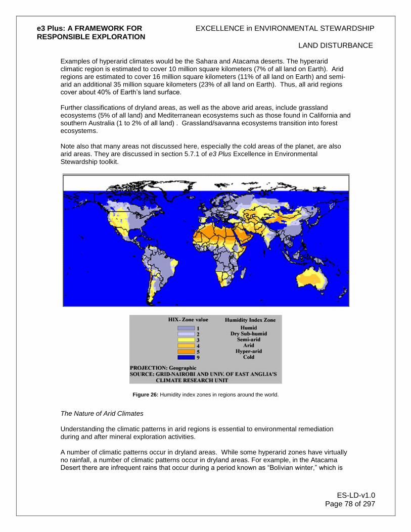
e3 Plus: A FRAMEWORK FOR EXCELLENCE in ENVIRONMENTAL STEWARDSHIP RESPONSIBLE EXPLORATION
LAND DISTURBANCE
ES-LD-v1.0 Page 78 of 297
Examples of hyperarid climates would be the Sahara and Atacama deserts. The hyperarid climatic region is estimated to cover 10 million square kilometers (7% of all land on Earth). Arid regions are estimated to cover 16 million square kilometers (11% of all land on Earth) and semi-arid an additional 35 million square kilometers (23% of all land on Earth). Thus, all arid regions cover about 40% of Earth‟s land surface. Further classifications of dryland areas, as well as the above arid areas, include grassland ecosystems (5% of all land) and Mediterranean ecosystems such as those found in California and southern Australia (1 to 2% of all land) . Grassland/savanna ecosystems transition into forest ecosystems. Note also that many areas not discussed here, especially the cold areas of the planet, are also arid areas. They are discussed in section 5.7.1 of e3 Plus Excellence in Environmental Stewardship toolkit.
Figure 26: Humidity index zones in regions around the world.
The Nature of Arid Climates Understanding the climatic patterns in arid regions is essential to environmental remediation during and after mineral exploration activities. A number of climatic patterns occur in dryland areas. While some hyperarid zones have virtually no rainfall, a number of climatic patterns occur in dryland areas. For example, in the Atacama Desert there are infrequent rains that occur during a period known as “Bolivian winter,” which is

e3 Plus: A FRAMEWORK FOR EXCELLENCE in ENVIRONMENTAL STEWARDSHIP RESPONSIBLE EXPLORATION
LAND DISTURBANCE
ES-LD-v1.0 Page 79 of 297
from December to March. The rains, however, can be torrential and cause considerable damage due to mudflows. They represent significant risks to exploration activities and communities. Arid and semi-arid climates often have alternating wet and dry seasons. The Mediterranean climate has cool wet winters and hot dry summers. In grassland and Mediterranean areas there are periodic droughts when vegetation is susceptible to fire, another significant risk to exploration and communities. The Nature of Arid Soils Soil is the unconsolidated material at the surface of the Earth that serves as the growth medium for plants. It is largely the roots of plants, both large and small, that hold the soil in place and slows the effects of climate on erosion of the surface. Soils are complex bodies including both inorganic and organic constituents. The organic constituents comprise the obvious plants that are visible at surface, but also many micro-organisms that are often in symbiotic relationship with the roots of visible plants. The primary direct effect of intrusive mineral exploration activities is on soil and vegetation. If road building and other intrusive activities are not done carefully, they can increase erosion both directly and indirectly by damaging the surface crusts and by removing or killing vegetation, thus creating channel ways for water. Soil usually forms as a result of the effects of climate (largely temperature and water) and micro- and macro-organisms which break down the constituents of the underlying rock. Soils in dry climates are generally poorly developed in terms of fertility as a direct or indirect result of the lack of water. The lack of water inhibits chemical reactions that break rock down into smaller particles. The lack of water also means less vegetation, leading to less biological effect on soil formation. Because of the lack of fertility, the lack of water and the sparse vegetation, desert soils and vegetation are exceedingly sensitive to disturbance. Once the vegetation, especially the root mass, is disturbed, the area is vulnerable to erosion and this can prevent vegetation from re-establishing itself. In hyperarid climates, the ground has virtually no soil development as there is little or no surface water and often no vegetation. In this type of climate, the main causes of the formation of soil-like material at the Earth‟s surface are wind and temperature. Ground water may also have some effect. Wind blows sand and dust sized particles that scour and erode rock faces and boulders and also damages vegetation. Although it might seem that desert soil in hyperarid regions should be loose and sand-like with little or no organic activity, neither of these assessments is totally true. Despite the fact that they are deserts, most hyperarid areas are not covered in sand. The soil surface in the driest deserts is often held together partly by material that gives many desert areas the various hues of red, brown and black. In North America, this material is referred to as “desert varnish”. Desert varnish is largely made of clay that cements particles of manganese and iron oxides to exposed rock surfaces. The varnish layer, often only 0.01mm thick, is created by colonies of bacteria. It is suggested that the varnish can take up to 10,000 years to form a complete coating.

e3 Plus: A FRAMEWORK FOR EXCELLENCE in ENVIRONMENTAL STEWARDSHIP RESPONSIBLE EXPLORATION
LAND DISTURBANCE
ES-LD-v1.0 Page 80 of 297
Figure 27: Drill roads and on upper left, old trench, Atacama Desert, Chile. Illustrates very slow recovery of old trenches in very arid environment. Also clear is the very visual and permanent effect of roads in this environment.
(Photo courtesy Noranda 2004)
A second type of material that holds deserts soils together is “caliche”, sometimes called “hardpan”.
Figure 28: Gravelly arkosic channel sand overlying dense array of caliche nodules (light grey) developed in mud overbank deposit. In: http://www.geo.sunysb.edu/lig/Field_Trips/hartford-basin/

e3 Plus: A FRAMEWORK FOR EXCELLENCE in ENVIRONMENTAL STEWARDSHIP RESPONSIBLE EXPLORATION
LAND DISTURBANCE
ES-LD-v1.0 Page 81 of 297
Caliche forms when soil pore water or ground water bearing magnesium and calcium carbonates evaporates at the soil surface, leaving behind a hard layer of carbonate, either at the soil surface or often just below the surface. Caliche has negative effects on plant life, for three reasons: 1. Most plants‟ roots cannot physically penetrate the hard layer. Consequently, the plants have
shallow roots and are more susceptible to drought or disturbance (natural, such as wind, or man-made such as bulldozing) than plants where there is no caliche layer.
2. The caliche causes high pH making iron and other micronutrients less available or unavailable to plants.
3. Water drainage is poor in caliche areas. Rather than water soaking into the soil to be available to plants for slow absorption, water rapidly runs off the surface leaving little behind.
In some cases, the roots of larger older trees penetrate the caliche to reach the underlying water table. These trees, in effect, pull water from below the caliche to the surface and create a local micro-ecosystem where other plants can flourish. Operating in Arid Climates Introduction Due to the poor soil development and lack of vegetation, any disturbance of arid land tends to be visually and ecologically apparent for very long periods. This is illustrated, for example, by studies and documentation of military operations in the western USA (see Table 1 below). It is also apparent in historic archaeological remains that show man‟s impact on the landscape from thousands of years ago. Native American trails in the western USA that were used only for foot travel are still visible hundreds of years later. In South America the “Camino del Inca,” a foot trail used for communications by the Incas, is still clearly visible in Chile and Peru and is a tourist attraction. The most important principle to apply when exploring in arid climates is to reduce initial impact and to eliminate, as much as possible, the need for reclamation as it may be impossible or extremely difficult to achieve. In addition, similar to alpine areas, aesthetic effects on landscape are extremely important as they are so long lasting.
Table 3: Estimated natural recovery times in years for California desert plant communities subjected to various anthropogenic impacts (selected from Lovich and Bainbridge, 1999).
Impact Location T recovery (Years)
Tank tracks Eastern Mojave 65, 76
Tent areas Eastern Mojave 45, 58
Dirt roadways Eastern Mojave 112, 212
Tent sites Eastern Mojave 8-112
Tent roads Eastern Mojave 57-440
Parking lots Eastern Mojave 35-440
Main roads Eastern Mojave 100-infinity
Military operations Eastern Mojave 1500-3000
Fire Western Colorado
Desert
5
Off-road vehicle use Western Mojave probably centuries
Pipeline (berm and trench) Mojave Desert 100
T recovery = estimated time in years to natural recovery

e3 Plus: A FRAMEWORK FOR EXCELLENCE in ENVIRONMENTAL STEWARDSHIP RESPONSIBLE EXPLORATION
LAND DISTURBANCE
ES-LD-v1.0 Page 82 of 297
Table 4: Adverse impacts on California desert, their relative intensity and historical occurrence (selected from Lovich and Bainbridge, 1999).
Impact Intensity Current/Historic
Grazing Moderate Primarily historic
Invasive plants Moderate/severe Historic/current
Highways Severe Current
Urbanization Severe Current
Off-road vehicles Severe Current
Agriculture Severe Both
Military operations Severe Both
Mining Locally severe Both
Linear corridors Locally severe Current
Studies reported by Lovich and Bainbridge on military camps show that, in terms of environmental degradation, tent camps had the least effect on the environment, tank tracks were intermediate and roads had the most effect. Exploration camps may have greater effect on the environment than 20
th Century military camps, but tank tracks are comparable to drill access and
the roads analogous to the more permanent roads that an exploration company may construct. If these research results are in fact applicable to exploration, then roads and drill pads are likely to be the cause of the most damaging impact in terms of area covered and intensity of effect. The basic principle to apply in arid regions is to:
MINIMIZE INTENSITY, FREQUENCY AND AREA OF DISTURBANCE. Water Use Water can be one of the most contentious issues in an exploration project. This includes both the use of water supplies and concern for the potential to contaminate water supplies. This might be especially true in arid climates where water resources are scarce. It is critical that water use be reduced as much as possible in camp and drilling activities and that extraordinary lengths be taken to avoid contamination of the few water sources that are present. Water contamination may result from camp activity such as waste management or sewage disposal, from road building or use, or from drilling. In many cases, discharged water must be kept away from natural water sources. It is important to understand the nature of the discharged water in relationship to the body of water into which it is to be discharged. An important question to consider would be: Is the water from a small camp, purified to a significant degree, using a properly designed sanitation system and going into a relatively large body of water, or is it of questionable quality and potentially discharging into a small body or stream that contains fish? Advanced exploration might also have to consider such issues as water discharge from exploration adits. The water level in scarce surface water bodies should not be lowered significantly as the local ecology and local inhabitants and their livestock are likely dependent upon it. All access to local water should be discussed and negotiated with the community (see the Community Engagement, and Land Management Sections under e3 Plus Social Responsibility Toolkit).

e3 Plus: A FRAMEWORK FOR EXCELLENCE in ENVIRONMENTAL STEWARDSHIP RESPONSIBLE EXPLORATION
LAND DISTURBANCE
ES-LD-v1.0 Page 83 of 297
Road Building and Use
Road building is the most important environmental issue for arid climate exploration as it is the largest surface disturbance, it creates significant lasting visual scarring of the landscape, and it can also stress the area by inviting in more vehicles which creates added ecological stress. Impacts include:
More camps from off-road tourists and hunters.
Invasive or foreign plant species attached to vehicles.
As the road becomes more rutted, it concentrates water flow during seasonal torrential rains, resulting in even more severe water erosion.
It also may change the local drainage patterns and affect groundwater.
Disturbance of desert crusts also increases soil susceptibility to wind erosion. Vehicles can often travel easily in the flatter deserts without having to create roads; however this results in tracks that may end up causing more problems than building a road. Roads can be engineered to minimize their impact, but tracks usually deteriorate far more quickly. The end result of tracks is that drivers are tempted to drive parallel to the existing track. The wheels of an off-road vehicle have been shown to impact half a hectare per 6 kilometers traveled. Multiple parallel passes by vehicles can increase that considerably. The problem is that, in many cases, the vehicle use breaks up the desert varnish thus creating conditions for wind erosion and, in others, the vehicles compact the already hard ground or duricrust, making it even more difficult for plants to maintain, or regain, a hold. Consequently the track size increases, and becomes more susceptible to water and wind erosion. Numerous studies have been completed, especially in western USA, of off-road vehicle impacts. The impacts can be summarized as follows:
The primary damage is caused by compaction of the soil.
The degree of compaction increases with the frequency of vehicle use.
Most susceptible to compaction are loamy sands and coarse gravelly soils.
Wet soils are more susceptible than dry.
Clay soils are least susceptible.
Figure 29: Photograph demonstrates depth of erosion due to cut and soil loss on off road vehicle trail. Tape has been strung horizontally to depict the unaffected ground surface. Last Chance Canyon, California (picture courtesy of San
Diego Office, California State Parks)

e3 Plus: A FRAMEWORK FOR EXCELLENCE in ENVIRONMENTAL STEWARDSHIP RESPONSIBLE EXPLORATION
LAND DISTURBANCE
ES-LD-v1.0 Page 84 of 297
Mitigating the Effects of Roads In order to minimize the impact of access trails or roads, the following issues should be considered in arid areas:
Can you walk instead of driving?
Use as few access routes as possible.
To the extent feasible, limit road access to other users.
Be aware of what the road is for and how long it will be used (for example, the main access route may be used for many exploration seasons whereas the road to a drill site might be only used for a matter of days).
It may be better to build roads rather than just drive through the desert if the route is to be used more than a few times.
If the road is to be used for a number of seasons, design the road construction to strengthen the bed so that it will not deteriorate rapidly.
If the road is to be used for only one season, do not over-engineer it. Afterwards, scarify the land to undo the compaction caused by the weight of vehicles.
Route access roads through gently sloping areas to minimize erosion.
When a hillside road is crossing a stream it should not continue at the same angle to the slope, as it will create a drainage route that will compete with the streambed, altering the drainage pattern. At the stream location a depression filled with rocks will ensure that the water will continue in the same bed.
In some cases, route the road through areas of colonizing vegetation, as it will tend to naturally reclaim the ground but consider the caveats below.
When preparing a trail using a bulldozer, avoid blading the soil aside; instead minimize moving of soil and overburden and leave plant root systems intact as much as possible. The vegetation will recover far faster.
Do not route through vegetation used as grazing or other purposes by communities.
Avoid disturbing plants that are nitrogen fixers (for example paloverde trees, acacia and mesquite).
Go around and do not disturb large plants or trees. An example is the saguaro cactus of northern Mexico and the USA which takes hundreds of years to grow. Large plants have deep root systems that are critical to the ecosystem.
When exploration is finished, soil loosening techniques will reduce the effects of compaction.
The on-site project manager should be responsible for ensuring that staff, such as bulldozer operators, drillers, geologists or others do not take short cuts off road, in effect creating multiple new routes.

e3 Plus: A FRAMEWORK FOR EXCELLENCE in ENVIRONMENTAL STEWARDSHIP RESPONSIBLE EXPLORATION
LAND DISTURBANCE
ES-LD-v1.0 Page 85 of 297
Figure 30: Picture illustrates deep dust formation due to repeated vehicle passes over same area, exposing location to potential soil removal due to wind or rain (picture courtesy of San Diego Office, California State Parks)
Stream Crossing
Although stream crossings may seem unimportant, especially in areas where the streams are all dry, some arid climates can have considerable rain in short periods of time. Because of the critical nature of water in this type of climate, stream crossings must be given the same serious consideration as in wet climates. Planning of the optimum approach to the stream bed or flowing stream crossings should aim to achieve the least disturbance and eliminate as far as practical the chance of water contamination. When planning stream crossings, the following should be taken into account:
How long and often is the access to be used and in which season?
Is water flowing during the access period? If so, then a culvert or other system is probably optimum.
Is the stream small and can it be bridged by a simple structure that keeps vehicles out of the water but allows water to continue to flow unimpeded?
Is the stream bed dry? Is it likely to stay dry during the exploration season? If the stream starts flowing can you avoid using the crossing during the period? If the answer to these questions is yes, then it is possible that a “ford type crossing”6 may cause least disturbance.
How resistant will the structure be to a sudden torrential rain storm and a flash flood? How quickly could it be removed if necessary?
Are all camp areas, equipment and fuel storage locations well away from potential flash flood areas?
Are adequate emergency response plans and communications capability in place in areas susceptible to flash floods?
6 www.gbcma.vic.gov.au

e3 Plus: A FRAMEWORK FOR EXCELLENCE in ENVIRONMENTAL STEWARDSHIP RESPONSIBLE EXPLORATION
LAND DISTURBANCE
ES-LD-v1.0 Page 86 of 297
Figure 31: Mountain streams in arid climates often have vegetation adjacent that is susceptible to disturbance. Southern
Andes of Chile. Photograph: Bill Mercer
Drilling All considerations listed for roads above apply to the construction of access and drill pads for any form of drilling in arid climates. A key factor is the length of time the access route will be used, and whether it will be reused in the future. Reverse circulation drilling, and other similar methods such as percussion, as well as the access issues, also produce significant dust that requires control. This is an issue for environmental, health and safety and aesthetic reasons. In addition, the rigs are often very large, which increases the area required for the drill to stand. Diamond drilling, in addition to the issues noted above, also requires large volumes of water, resulting in the following considerations:
Is sufficient water available without negatively impacting ecology or people in the area?
Is access to the water possible without risking contamination?
If ground waters are used, will the pumping of them negatively impact springs, or other water courses nearby that people or the ecology are dependent upon?
Are the ground waters saline or poisonous such that they could have a negative impact on the environment? What if a drill hole makes water and the water is high in heavy metals – do you have a plan in place?
Does the drill company have a system in place to handle the water after drilling to ensure that there is no contamination of surface or ground waters?
Water supply is critical to mine development in arid areas. Considerable detailed information can be obtained during the drill program related to aquifer size, ground water table and flows, ground

e3 Plus: A FRAMEWORK FOR EXCELLENCE in ENVIRONMENTAL STEWARDSHIP RESPONSIBLE EXPLORATION
LAND DISTURBANCE
ES-LD-v1.0 Page 87 of 297
water quality and other parameters that will be critical to future environmental impact assessments and project design. Consideration for the collection of this data should be included in the drilling program to reduce delays and reduce costs in the event that the program leads to mine development. Living organisms have been found in ground water sources, and identification of them at early stages can minimize impact and ensure adequate management. Of course, with some forethought, the drilling may be positive for a local community if it creates access to groundwater that was previously in short supply. Trenching
Trenches have often been dug in arid climates and not reclaimed, perhaps because people viewed them as no different to natural gulleys. However, trenches are aesthetically unpleasing eyesores that damage the reputation of the industry and should be reclaimed for this reason alone. The difference between a trench and a natural gulley can be seen in the colours of the rock where the trench is a scar because it exposes unweathered material. Apart from aesthetic concerns, trenches, depending on the size and shape, can also be a safety hazard to animals and people. When trenching in arid climates the same considerations apply as in other situations (see Sections 6.10 and 14.2 of e3 Plus: Excellence in Environmental Stewardship) The topsoil should be separated from any rock dug out of the trench so that the material can be returned in the order it came out of the trench. Although desert soils may appear relatively structureless, usually there is still a structure present. If the climate is suitable for vegetation to grow, then the surface of the trench, once reclaimed, should be planted (see reclamation below).
Figure 32: Picture illustrates slow recovery of desert. Erosion gulleys still clearly visible 25 years after off road vehicles were fenced out. Tuttle Ridge, Red Rock Canyon State Park, California. Taken 2005 (picture courtesy of San Diego
Office, California State Parks)
It may appear that in arid environments acid rock drainage is not important. In fact, due to the scarcity of water, it is still an important issue. As a result the disposal of sulphide bearing rock must take this into account and precautions taken to reduce the risk.
e3 Plus: A FRAMEWORK FOR EXCELLENCE in ENVIRONMENTAL STEWARDSHIP RESPONSIBLE EXPLORATION
LAND DISTURBANCE
ES-LD-v1.0 Page 88 of 297
Other Activities Many normal exploration activities such as geological mapping, geochemical sampling and geophysics, have very minimal impact in many environments where there is abundant vegetation. However, in arid climates seemingly innocuous work can have long lasting effects. The most common problem is the use of vehicles off-road in order to ease geophysical surveys and the carrying of geochemical samples. Sometimes geologists will be tempted to drive to every outcrop instead of walking. This should clearly be discouraged. Reclamation
Key to reclamation is planning.7 In areas that are particularly ecologically sensitive or with high aesthetic or cultural value, reclamation plans should be researched and tested in advance. Due to the nature of arid lands, revegetation with native species requires access to native plants from nurseries and/or seed, both of which might not be readily available on short notice. If seed collection is required for a nursery to grow plants, allow at least 6 months for growth of the seedlings. Seed collection should be done by experienced people who can recognize mature seeds. Examine the possibility of saving plants that are to be disturbed and using them later in revegetation. Also, where it is difficult to obtain or grow from seed, division of existing plants may be possible, such as “coiron,” a grass that grows in tufts in Chile. In some cases, there should be consideration of utilization of faster growing, commercially available nurse crops to aid early soil formation, reduce wind and water erosion, protect slower growing native plants and to encourage water infiltration. However, these must be carefully considered to ensure that new species are not introduced at the expense of native species. There must be a contingency plan in place in case seed or plants are not available, or planting is unsuccessful. Apply a few solutions (scarifying, seeding, planting, water enhancement, etc.) rather than depending on the success of one. Reclamation is also an excellent opportunity to use local labour, thus increasing the positive input to the community and enhancing community relations. Local farmers or ranchers may also understand the ecology, knowing what grows easily and what does not, having lived with it for long periods, if not generations. In areas where snow is a significant proportion of the precipitation, vegetation may trap snow in branches. When planting a tree or shrub, it may be possible to create a small artificial trap for snow by created a depression around the trunk, thus increasing the moisture content of the soil. As soon as work stops and an area is to be reclaimed, measures should be taken to ensure that the area does not deteriorate further. This may include restricting access to unauthorized people as far as possible.
7 see D. Bainbridge, 1995: A Beginners Guide to Desert Restoration
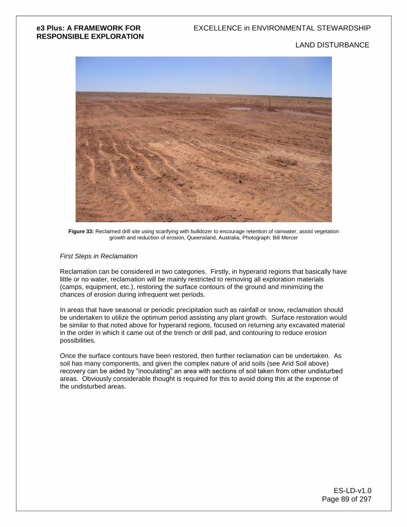
e3 Plus: A FRAMEWORK FOR EXCELLENCE in ENVIRONMENTAL STEWARDSHIP RESPONSIBLE EXPLORATION
LAND DISTURBANCE
ES-LD-v1.0 Page 89 of 297
Figure 33: Reclaimed drill site using scarifying with bulldozer to encourage retention of rainwater, assist vegetation growth and reduction of erosion, Queensland, Australia, Photograph: Bill Mercer
First Steps in Reclamation Reclamation can be considered in two categories. Firstly, in hyperarid regions that basically have little or no water, reclamation will be mainly restricted to removing all exploration materials (camps, equipment, etc.), restoring the surface contours of the ground and minimizing the chances of erosion during infrequent wet periods. In areas that have seasonal or periodic precipitation such as rainfall or snow, reclamation should be undertaken to utilize the optimum period assisting any plant growth. Surface restoration would be similar to that noted above for hyperarid regions, focused on returning any excavated material in the order in which it came out of the trench or drill pad, and contouring to reduce erosion possibilities. Once the surface contours have been restored, then further reclamation can be undertaken. As soil has many components, and given the complex nature of arid soils (see Arid Soil above) recovery can be aided by “inoculating” an area with sections of soil taken from other undisturbed areas. Obviously considerable thought is required for this to avoid doing this at the expense of the undisturbed areas.
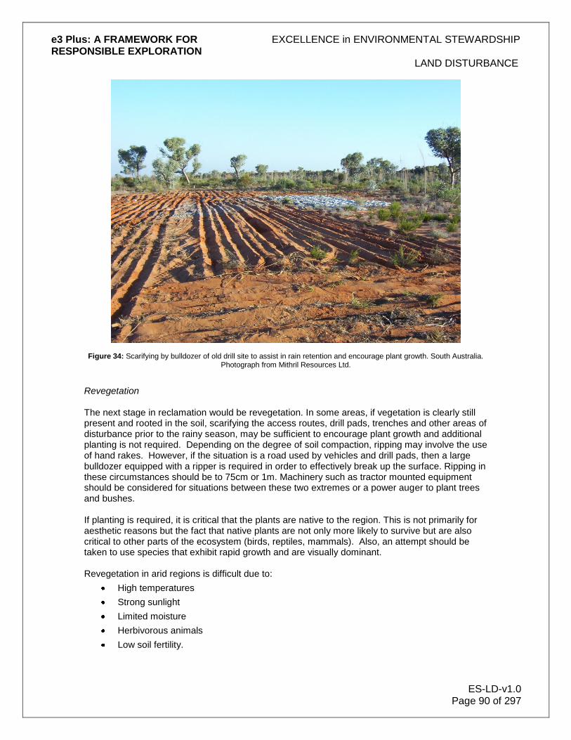
e3 Plus: A FRAMEWORK FOR EXCELLENCE in ENVIRONMENTAL STEWARDSHIP RESPONSIBLE EXPLORATION
LAND DISTURBANCE
ES-LD-v1.0 Page 90 of 297
Figure 34: Scarifying by bulldozer of old drill site to assist in rain retention and encourage plant growth. South Australia. Photograph from Mithril Resources Ltd.
Revegetation The next stage in reclamation would be revegetation. In some areas, if vegetation is clearly still present and rooted in the soil, scarifying the access routes, drill pads, trenches and other areas of disturbance prior to the rainy season, may be sufficient to encourage plant growth and additional planting is not required. Depending on the degree of soil compaction, ripping may involve the use of hand rakes. However, if the situation is a road used by vehicles and drill pads, then a large bulldozer equipped with a ripper is required in order to effectively break up the surface. Ripping in these circumstances should be to 75cm or 1m. Machinery such as tractor mounted equipment should be considered for situations between these two extremes or a power auger to plant trees and bushes. If planting is required, it is critical that the plants are native to the region. This is not primarily for aesthetic reasons but the fact that native plants are not only more likely to survive but are also critical to other parts of the ecosystem (birds, reptiles, mammals). Also, an attempt should be taken to use species that exhibit rapid growth and are visually dominant. Revegetation in arid regions is difficult due to:
High temperatures
Strong sunlight
Limited moisture
Herbivorous animals
Low soil fertility.

e3 Plus: A FRAMEWORK FOR EXCELLENCE in ENVIRONMENTAL STEWARDSHIP RESPONSIBLE EXPLORATION
LAND DISTURBANCE
ES-LD-v1.0 Page 91 of 297
Larger plants have been successfully raised in nurseries and transplanted. A hand power auger is useful in order to efficiently create holes deep enough for larger plants. It is important that the plants are protected as far as possible from future disturbance. This means that larger species such as trees or shrubs should have collars and/or wire mesh to protect them from grazing species – either small or large (rodents, deer, and cattle).
Figure 35: Revegetation activities in Brazil (photo courtesy Falconbridge)
Where this is impractical, rocks or brush can be placed around plants. A hand power auger is useful in order to efficiently create holes deep enough for larger plants. Once the plant is in the ground and a protective collar applied, the plant should be irrigated at least once. Again, it is critical to plant just prior to, or during, the wet period. In addition, mulch within the plant collar can assist in maintaining the soil moisture content. It has been documented that mulch comprising larger fragments (for example, bark or chunks of wood) is more successful than fine material as it decomposes more slowly and is less likely to be blown away. Fertilizer is generally not recommended as it has been shown that it does not increase plant survival rate, and in fact can decrease it. Smaller plants can be seeded mechanically or by hand, however, it should be born in mind that desert plants are difficult to grow from seed in the wild. In light of this, in any difficult environment, it is suggested that expert local advice be obtained prior to considering a program of seeding. Finally, it is important to document the reclamation procedures followed both in writing and with digital photographs. The purpose is to monitor the success of the program over the long term (at least one year) and to disseminate the lessons learned, at least within your company and preferably to industry as a whole. If the program is unsuccessful, a contingency plan should be in place for an alternative method. Community Relations When conducting exploration in arid environments, the concerns of communities are especially important due to the scarcity of water and the requirement of sufficient clean water for human

e3 Plus: A FRAMEWORK FOR EXCELLENCE in ENVIRONMENTAL STEWARDSHIP RESPONSIBLE EXPLORATION
LAND DISTURBANCE
ES-LD-v1.0 Page 92 of 297
survival. Exploration programs must take into account the requirements of the inhabitants of such sensitive regions and ensure that there are no adverse effects on the water that they depend on or the sparse vegetation that they or their livestock depend upon. In some cases, the people may not be empowered politically to defend their needs and the company must be mindful of the impacts and make allowances for this (See the Community Engagement/Development section in e3 Plus Social Responsibility toolkit).
Figure 36: Deep trenches are often required in tropical to semi-tropical terrain to assess saprolitic deposits. If used, project managers must seriously address issues of safety for the workers. © Iamgold.
With deep weathering in both arid and tropical terrain, pitting and trenching are important tools for mineral exploration in these regions. The pits and trenches, often several metres deep, allow a geologist to penetrate the saprolite layer and have a means of determining underlying rock type. In many cases, a trench also provides a means of sampling mineralized saprolite to determine grade. Trenches and pits in saprolite are surprisingly stable when dry but excavation and entry should not be attempted during the rainy season. Trenches should be filled in after mapping and sampling, carefully ensuring that the segregated topsoil is added at the end of back-fill to allow rapid revegetation. It is worth noting that deep trenches in saprolite should always be checked before entering to ensure there are no dangerous animals present such as snakes, scorpions or spiders. It should also be noted that some jurisdictions have regulations limiting the amount of trenching and pitting that is allowed within a given area (hectares or square kilometres) of arid or tropical terrain. All the usual procedures and precautions apply during drilling programs in arid and tropical terrain although there may be unique logistical and technical problems to be resolved beyond the scope of this discussion. It should be noted that some jurisdictions have regulations limiting the number of drill sites per hectare, the size of drill pads and the use of drilling additives. Cementing of drill hole collars may be required upon completion of the program. Great care must be taken, especially in arid to semi-arid areas, to ensure that the water table is not lowered and that water quality is not compromised in any way.

e3 Plus: A FRAMEWORK FOR EXCELLENCE in ENVIRONMENTAL STEWARDSHIP RESPONSIBLE EXPLORATION
LAND DISTURBANCE
ES-LD-v1.0 Page 93 of 297
Figure 37: Drilling in arid terrain can present logistical and environmental challenges. © Iamgold
Figure 38: Lightweight, modular drill rigs can mitigate environmental disturbance in tropical terrain. © Kluane Drilling
5.7.3 Riparian Areas
The area where land and water meet is called the riparian zone. It is a transition zone, containing elements of both upland and aquatic ecosystems. Because of this, it is the most productive environment in the forest.
e3 Plus: A FRAMEWORK FOR EXCELLENCE in ENVIRONMENTAL STEWARDSHIP RESPONSIBLE EXPLORATION
LAND DISTURBANCE
ES-LD-v1.0 Page 94 of 297
Unless otherwise authorized, maintain a minimum 90 m buffer of undisturbed vegetation between all trenching, stripping, and drilling operations and any lakes, rivers or major streams. Leave a 30 m buffer of undisturbed vegetation between any water body and campsite, unless otherwise approved.
5.7.4 Wetlands
The term "wetlands", for the purpose of this e-toolkit, encompasses all poorly drained areas, for example:
Muskeg
Buttongrass plains (Australia)
Moors
Marshes
Page zones
Swamps
Mangroves
Bogs. Wetlands occur in a variety of locations from the High Andean Plateau (La Puna) to the high Arctic. "Riparian Terrain" is a form of wetland, transitional between permanently saturated wetlands and upland terrain. Lands adjacent to flowing rivers, glacial potholes, and the shores of lakes are typical riparian areas. These areas have vegetation and physical characteristics reflective of permanent surface or subsurface water influence. As with wetlands, riparian terrain occurs in most regions across the world. Both wetlands and riparian terrain are highly sensitive to environmental impact and generally take a long time to recover. Wherever possible, work in such areas should be avoided but, if essential, plan the work to minimize any disturbance. Schedule the program during low water season or, in colder climates, when the ground is frozen. These areas are often used by migratory birds as significant feeding and resting sites so avoid the annual migration season. All equipment brought across or into these areas should be cleaned of any residual soil and plant material from previous work to avoid introduction of non-native species of vegetation. These areas are highly sensitive to environmental impact and generally take a long time to recover. Avoid these areas wherever possible when locating roads/tracks. If it is necessary to cross these areas, try to do so during the seasonal period when the least amount of impact will be incurred (e.g., dry season, frozen, snow covered) and use low ground pressure vehicles. Tracks through wetlands usually result in highly visible scarring which lasts for many seasons. Any drilling activity in these areas must be conducted with extreme care. The drill site should be contained by a silt fence/oil boom/berm system to prevent release of any contaminants into the area. Drilling water should be re-circulated to avoid significant drawdown of the local water table. Where there is a possibility of holes 'making water', holes should be plugged upon completion of the program. Any disturbance of soil-binding vegetation should be minimized. As soon as work is completed, the area should be reclaimed as necessary by replanting and seeding with local vegetation while controlling sediment movement with silt fencing until the new vegetation matures.

e3 Plus: A FRAMEWORK FOR EXCELLENCE in ENVIRONMENTAL STEWARDSHIP RESPONSIBLE EXPLORATION
LAND DISTURBANCE
ES-LD-v1.0 Page 95 of 297
5.7.5 Beaches and Coastal Sand Dunes
Vegetated sand ridges called dunes, built up by dry beach sand blown inland and trapped by plants and other obstructions, back most beaches. As sand accumulates, the dunes become higher and wider. Stable sand dunes play an important part in protecting the coastline. They act as a buffer against wave damage during storms, protecting the land behind from saltwater intrusion. This sand barrier allows the development of more complex plant communities in areas protected from saltwater inundation, sea spray, and strong winds. The dunes also act as a reservoir of sand, to replenish and maintain the beach at times of erosion. Vegetation on beaches and on sand dunes tends to occur in zones, according to the degree of exposure to harsh coastal conditions. Closest to the sea is the pioneer zone, extending landward from the debris line at the top of the beach to the crest of the foredune, or frontal dune. Only specialized pioneer plants can colonize the seaward slope and crest of the foredune, as these areas are exposed to:
Salt spray
Sand blast
Strong winds
Flooding by the sea These plants are often protected by waxy or hairy coverings on stems and leaves, and grow low to the ground, offering little resistance to the wind. They have strong root systems and spread rapidly, creating a mesh of creeping stems, so if one part is buried in shifting sand or uprooted, another part can continue growing. They thus serve to stabilize the sand, forming and building dunes. Frontal sand dunes are vulnerable. The vegetation can be destroyed by natural causes, such as:
Storms
Cyclones
Droughts or fires The same effects can result from human interference, such as:
Clearing
Grazing
Vehicles
Excessive foot traffic If the vegetation cover is damaged, strong winds may cause "blowouts" or gaps in the dune ridge. Unless repaired, these blowouts increase in size, and the whole dune system sometimes migrates inland, covering everything in its path. Meanwhile, with a diminished reservoir of sand, erosion of the beach may lead to coastal recession. Sand dunes are prone to erosion by wind. Always strive to retain the full vegetation cover when working in dune country. Stabilization of sand dunes is often dependent upon their precise shape and their fragile vegetation cover. Minor cuttings or limited alteration of dune form can, in time, provoke blowouts. For these reasons, do not make tracks in areas of dune development unless they are absolutely essential.

e3 Plus: A FRAMEWORK FOR EXCELLENCE in ENVIRONMENTAL STEWARDSHIP RESPONSIBLE EXPLORATION
LAND DISTURBANCE
ES-LD-v1.0 Page 96 of 297
Ensure that grids are pegged, not cut, wherever possible. Dunes, with their covering of grasses and other plants, are so fragile that even footsteps can damage or kill the plants and weaken the dunes. Wherever possible, avoid driving vehicles on dunes, as the tires destroy dune vegetation, increasing the chance of dune destruction. It is therefore of vital importance to take whatever measures are necessary to protect the vegetation in areas of coastal sand dune development. Behind the frontal dunes, in areas protected from windy and salty conditions, vegetation depends on local circumstances (e.g., freshwater swamps, well-drained ridges). These zones are not fixed. As plants grow taller and humus (e.g., dropped leaves) accumulates, exposure to sun and soil conditions change. The soil becomes richer and holds more water. This enables scrub and woodland plants to move in, and the type of vegetation changes through a process called succession. There are other items to consider when operating in coastal areas. The hostile salt-water environment can play havoc with a camp, a program and, ultimately, a budget. Camps must be carefully planned so that electrical systems do not cause safety hazards. You must ensure that there is no possibility that sewage systems will contaminate the coastal waters or estuaries. Because of increased corrosion possibilities, greater care is necessary to avoid compromising fuel containment. Empty and partially used fuel drums should always be removed from camps and storage sites but this is particularly important in coastal areas where salt-laden mist will rapidly corrode steel and aluminum fittings. It is also worth noting that some jurisdictions define coastal areas by elevation above sea level. There are situations where elevations remain low for many kilometres inland from the ocean. Coastal regulations may apply in such areas even if apparently inappropriate.

e3 Plus: A FRAMEWORK FOR EXCELLENCE in ENVIRONMENTAL STEWARDSHIP RESPONSIBLE EXPLORATION
SITE MANAGEMENT
ES-SI-v1.0 Page 97 of 297
6.0 Site Management
The primary goal of a site management system is to ensure every person entering the site completes their business in a safe, environmentally sensitive and effective manner. This includes: contractors; visitors; inspectors; and senior company management. For the purposes of this e-toolkit, a site is any area where exploration and related activities are conducted by the company, its employees, contractors, and subcontractors, whether or not the company has land tenure. The following two examples would both be considered sites worthy of inclusion in a site management system: The location of a contracted prospector's parked truck on the shoulder of a highway, while the prospector is on a reconnaissance traverse. The boat or floatplane loading area of a public dock As described in the 2.2 Management Essentials section of this e-toolkit, site selection planning is an important factor in the safe and successful completion of any exploration program. Although access to water for consumption, hygiene, overburden stripping, sluicing, drilling, and transportation is an important factor in the site selection process, also consider the effects that the selection will have on soil erosion, local and regional water resources, ecosystem health, and future exploration programs. Mining operations often take advantage of infrastructure established by exploration crews, so planning (especially roads and camps) should consider potential long-term effects. In addition, be aware that water management and soil erosion control forms the bulk of environmental control activities at operating and closed mine sites. A site management system designed to effectively control safety, health, and environmental risks includes procedures, training, checklists and documentation, and inspection of the following elements:
Emergencies, accidents, spills and incidents
Notification and reporting
Noise, dust, and other air emissions
Water resources
Aquatic life resources
Wildlife resources
Archaeological and cultural resources
Materials management
Waste management
Traffic management This section offers guidelines for dealing with all aspects of site management, from large programs to small ones. Much of the information will be too detailed for a small program, but what is applicable can be extracted from the material presented here.
6.1 Health and Safety
Health and safety management systems are intended to ensure that every person leaves the site, or completes a shift, healthy and safe. Everyone on-site must be aware of, and familiar with the:

e3 Plus: A FRAMEWORK FOR EXCELLENCE in ENVIRONMENTAL STEWARDSHIP RESPONSIBLE EXPLORATION
SITE MANAGEMENT
ES-SI-v1.0 Page 98 of 297
Specific hazards associated with the site
System used to identify hazards
System for notifying the supervisor of an unsafe condition
System for reporting an incident
Emergency (notification and evacuation) plan
Daily safety topic, including hazardous activities and materials
System for participating in improvements to the site's health and safety performance
Forms and checklists required to document and assess the above Health and safety legislation, and the corresponding management system, is typically based on every person's:
Right to know
Right to refuse entry or work
Responsibility to report unsafe conditions
6.1.1 Health and Safety Management Systems
There are several elements of the site health and safety management system which are required to ensure that all field personnel will:
Know about, refuse to work under, and report hazardous conditions
Communicate new hazards and safety performance
Continually improve the system These elements include:
Updated site and workplace hazard information, labelling and controls
Updated hazardous material information references
Regular documented meetings, with posted minutes, to communicate hazards and discuss improvements
Regular documented workplace inspections
Documented worker and protective equipment audits
Documented planned inspections
Incident reports with root-cause analysis
Regular safety statistics reporting to site personnel and management In the case of a worker injury, report promptly to the appropriate authority (e.g. in Canada, a Workers' Compensation Board).
6.2 Housekeeping
Good housekeeping and an orderly site often reflect an effective management system. Good housekeeping is an important element of safety, especially relative to:
Tripping hazards
Hazardous material storage and handling
Hazard labelling and identification

e3 Plus: A FRAMEWORK FOR EXCELLENCE in ENVIRONMENTAL STEWARDSHIP RESPONSIBLE EXPLORATION
SITE MANAGEMENT
ES-SI-v1.0 Page 99 of 297
Good housekeeping is also an important element covered in any safety and environmental induction and training program. Ensure that the field crew practices good housekeeping in field camps and exploration operations. For most sites, housekeeping can be included as an element of a workplace safety audit, or a planned inspection focused on safety and environmental compliance with site programs and procedures. It is important to clearly mark, and properly manage, such potential tripping and rupture/spill hazards as:
Extension cords and electrical cables
Oxyacetylene hoses, water hoses, and air hoses
Temporary pipelines Other hazards can include:
Hand tools and power tools
Office boxes and files
Samples, backpacks, grub hoes, and shovels
Radio antennae and clotheslines
Paddles, boat motors, gas cans, and boating equipment
Work boots, rain gear, and work clothes that have been set aside to dry Orderly handling and storage of these items forms part of a good housekeeping program; ensure that regular and diligent documented inspection and follow-up are carried out.
6.2.1 Housekeeping and Hazardous Materials
In some instances, housekeeping will have to be expanded into a management system for hazardous and controlled material handling. The storage and handling of the following materials are regulated by legislation, or are known to require systems to control their use. For more detailed procedures and guidance, please refer to the 10.0 Hazardous Material portions of this manual. Develop and implement storage and handling systems for the following materials:
Fuels
Solvents
Lubricants
Flammables
Explosives and detonators
Compressed gas cylinders
Batteries
Bear spray
Ammunition and firearms
Acids
Certain rock, soil, and water samples Store fuels, solvents, lubricants and flammables in clearly marked areas that are:
Separate or protected from traffic
Away from ignition sources

e3 Plus: A FRAMEWORK FOR EXCELLENCE in ENVIRONMENTAL STEWARDSHIP RESPONSIBLE EXPLORATION
SITE MANAGEMENT
ES-SI-v1.0 Page 100 of 297
In well ventilated areas Store barrels or tanks that will be used to dispense smaller volumes of these materials within secondary containment vessels that can accommodate 110% of the primary storage container. Store, handle, and transport explosives and their detonators separately in secure, grounded, storage containers, free from any ignition source and 500 m from frequently used workplaces. More detailed requirements can be found in the 10.0 Hazardous Material section of this e-toolkit.
Store, handle, and transport compressed gas cylinders in an upright position, with the cap secured, and chained to a rack of appropriate strength and size to accommodate the cylinders. Store batteries, bear sprays, acids, ammunition, and samples away from high traffic areas, in secure, clearly labelled containers, free from any ignition sources, and well ventilated as required. Store firearms in secure containers, with trigger locks, separate from the keys/combinations and ammunition. Unlabeled, unmarked, or unsecured, controlled or hazardous materials or hazardous waste cannot be left in high traffic areas, under any circumstances.
6.3 Monitoring and Inspections
It is important that monitoring and inspections be designed to:
Ensure programs and procedures are effective
Ensure persons on-site are effectively using the programs and procedures
Ensure that site activities are compliant with programs and procedures
Document the status of the site
Ensure hazards and risks are identified, assessed, and communicated
Help complete reports on safety and environmental performance
Help improve the safety and environmental performance by aiding in the review and revising the programs and procedures
The following tools can be used to help manage monitoring and inspection programs:
Checklists
Action plans
Regular schedules
Proper tools and equipment
Databases Checklists are an excellent method of documenting inspections and monitoring. Checklists help to ensure that the information collected is consistent, and they act as a reminder to the inspector or sampler. Action plans with schedules, and responsible persons regularly assigned to the monitoring and inspection tasks, are important tools. They act as reminders to site personnel, and ensure that information and samples are collected at the right time. Regularly scheduled inspections are the easiest to remember. For example, most people will find it easy to remember to check the generator fuel tank level every morning after coffee break.

e3 Plus: A FRAMEWORK FOR EXCELLENCE in ENVIRONMENTAL STEWARDSHIP RESPONSIBLE EXPLORATION
SITE MANAGEMENT
ES-SI-v1.0 Page 101 of 297
As noted above, monitoring and inspections are most successful when completed regularly, using the proper tools and equipment for the task at hand. Using databases or spreadsheets is an excellent method of tracking the information collected. It is best if the databases and spreadsheets are updated by the company or the field operators, immediately upon collecting the information. Make sure that this is done by the person who collected the information. Inevitably, there will be data integrity problems if an employee tries to enter data a month or two after it is collected.
6.4 Site Clearing
Initiate site clearing only after obtaining appropriate authorization and approval from local and regional regulators or communities. The site-clearing plan should include:
Vegetation removal, stockpiling, and end-use procedures
Overburden stockpile handling, storage, and reuse procedures
Sand, till and gravel removal, storage, and use procedures
Water resource impact control procedures
Resource, artifact, fossil, and environment value protection procedures
Refer to the 5.0 Land Disturbance section of this e-toolkit for more detailed guidance about on-site clearing issues. It is important to account for all materials moved during the clearing and to stockpile these materials to facilitate future use. In particular, save overburden and existing soil for revegetation. Do not excavate sand, till, or gravel below the water table without obtaining approval for water pump-down and materials extraction plans. Stack trees for future use or use by others. Approve any alternatives to these general procedures prior to proceeding with site clearing.
6.5 Drainage Control
If a small exploration program is planned, it may not require much in the way of drainage control. However, larger camps and associated activities will often require diverting fresh water, referred to here as run-on, and collection of contaminated run-off. In these cases, ensure that all ditches and berms are constructed to withstand the hydraulic energy of extreme precipitation and run-off events. Typically, ditches and berms are constructed with slopes of 2H:1V (2 horizontal to 1 vertical). Revegetate and protect ditches with rip-rap (loose rock), or appropriate engineered material, to control erosion and siltation. If revegetation berms, remove shrubs and trees to prevent destabilization of the berm core by extensive, water-seeking root systems. Form berms and ditches into impervious or well-prepared foundations.
6.5.1 Run-on
You need to control run-on in order to minimize the volume of fresh water exposed to contaminants associated with exploration activities. Diversion berms and ditches prevent run-on and re-route it to nearby receiver creeks, rivers, wetlands, lakes and oceans. You should consult

e3 Plus: A FRAMEWORK FOR EXCELLENCE in ENVIRONMENTAL STEWARDSHIP RESPONSIBLE EXPLORATION
SITE MANAGEMENT
ES-SI-v1.0 Page 102 of 297
geotechnical experts for the design and construction of berms that retain water or divert existing rivers. However, you can construct small check dams with bales of hay to divert intermittent brooks running across a drill site, for example, which can easily improve the problems associated with managing contaminated water. As with most of the management systems described in this manual, you should develop run-on plans prior to the start of the exploration program by determining the basic hydrology of the area to be worked. A topography map will provide you with the basis of a simple and effective run-on plan. As far as possible you should plan camps, drill sites, and extensive excavations off the line-of-fall of water draining to nearby valleys and low areas.
6.5.2 Runoff
Silt, spilled fuel, and leaked oil are contaminants that, once in water, require proper management in order to protect the local watersheds and their ecosystems. Once run-on hits your site, the runoff, or water that drains from the site toward a downstream water resource, may require management. The contaminants noted above are common to most exploration sites, and you can manage them easily. Other contaminants, such as those resulting from spills, will require you to give them
special handling as described in more detail in the 10.0 Hazardous Material and 11.0 Spill Management sections of this manual.
The more difficult contaminants for you to manage are those that cannot be seen and those that may, or may not, be released. For example, metals and radioisotopes from rock and soil samples, drill dust and muds, core shack dust, or channel and chip sampling programs can contaminate nearby water resources and go undetected. You should conduct a baseline water quality sampling program to help you to measure if, and to what extent, metal contamination has occurred. However, the most conservative approach is for you to ensure that these products do not enter the receiving watershed by managing their production, handling and disposal. You should refer to the Sample Handling section below for more details. You will find that silt fences, made of fabric or hay staked in the path of solids contaminated runoff, and settling ponds can help reduce the release of cloudy, suspended solids-laden runoff to the receiver watershed. You should use absorbents to clean up leaked and spilled fuels and oils before they are released to water. In the event of release to water, you can use oil booms and pads to ensure these contaminants are not released to the environment. Water treatment for metals control is complicated by the combination of metals in water and the characteristics of the water itself. Most heavy metals are not dissolved in water at neutral pH. Metals such as nickel and zinc, once dissolved in water, do not precipitate until the pH of the contaminated wastewater is brought up to 9.5 to 9.8. If water is acidified by exploration activities, or natural features, then other heavy metals such as copper, lead and cadmium can be dissolved as well. To avoid treatment of acid-and metal-bearing wastewater, you should prevent pulverized, crushed sulphides and iron-rich exploration by-products from being released to the environment, from subsequent exposure of them to air and water and their consequent oxidation to form acid wastewater. The following subsection discusses sulphide waste.

e3 Plus: A FRAMEWORK FOR EXCELLENCE in ENVIRONMENTAL STEWARDSHIP RESPONSIBLE EXPLORATION
SITE MANAGEMENT
ES-SI-v1.0 Page 103 of 297
Sulphide Waste
In the early stages of exploration the most likely sources of sulphide-bearing waste will be trench samples and drill core. You should characterize, handle and manage sulphide-bearing waste separate from other waste materials, in order to avoid costly, and long-term, treatment requirements. You should ensure that, wherever possible, you minimize the exposure of sulphide waste to surface water, since sulphides readily oxidize and form sulphuric acids that dissolve metals into site run-off. You should therefore make every effort to avoid acid generation at source by dealing properly with the sulphides before they have an opportunity to oxidize.
You should refer to the 12.0 Waste Management section of this activity, in Waste Rock
Disposal under On-site 12.0 Waste Management for further details of the handling of sulpide-
bearing waste.
6.6 Maintenance
Maintenance of equipment typically involves handling and disposal of hazardous materials such as: lubricants; hydraulic oil; fuels; coolants; paints; solvents; compressed gas cylinders; flammables; and acids. Each of these substances poses safety and environmental hazards that need to be controlled with an appropriate management system. For more detail on the storage, handling and disposal of maintenance consumables, refer to the sections in this e-toolkit on 10.0 Hazardous Material, 11.0 Spill Management, and 12.0 Waste Management. In general, maintenance is best performed on a schedule prior to problems and repairs being required. A preventative maintenance program includes:
A schedule
A proper inventory of consumables and spare parts
A designated location for maintenance
The proper tools to complete the job
Trained personnel who can ensure the maintenance is completed safely and effectively Bear in mind that improper maintenance and the use of improper parts or tools can be more hazardous than no maintenance, and can lead to injury or spills. When maintenance is required, ensure that it is performed:
In well-ventilated areas
With a floor or drop cloth that can be thoroughly cleaned
At a safe distance from ignition sources
At a safe distance from water resources, including groundwater resources
6.7 Security
Secure exploration sites from entry by the public, as this is the only method of protecting the public from the hazards associated with exploration activities. The site owner is ultimately responsible for the safety of everyone on the site, especially in the event of an emergency or debilitating injury. Properly securing a site from acts of vandalism also helps to prevent safety and environmental incidents.
e3 Plus: A FRAMEWORK FOR EXCELLENCE in ENVIRONMENTAL STEWARDSHIP RESPONSIBLE EXPLORATION
SITE MANAGEMENT
ES-SI-v1.0 Page 104 of 297
Site security can be as simple as identifying site boundaries, or as elaborate as the use of fences, gates, surveillance, full-time security personnel, vehicle inspections, random searches, and detection equipment. The requirements will have to be determined at each site, based on access, hazards, and overall risk. Access typically relates to the likelihood of an incident, while hazards relate to the consequence associated with the occurrence of an incident. Where public access to the site is possible, implement an appropriate security system. At the most basic level, post signs at the site boundary at its point of access, noting:
Company and property name
Access restrictions or conditions ("must report to")
Contact personnel and information
Authority under which access is restricted
Hazard warnings
Emergency notification, reporting, and response procedures
In more advanced projects, and in order of increasing project risk, other security options include:
Signs restricting access or identifying hazards along site boundaries adjacent to access routes
Gates and appropriate lights and reflectors, restricting vehicle access
Gates and fences, restricting any access
Lights
Surveillance equipment
Security personnel
6.7.1 Induction and Orientations
Regardless of the method of entry onto the site, you should ensure that your site security management systems include safety and environmental inductions. You should complete these with all persons entering a site, including
Visitors, inspectors, officers, managers, executives, and shareholders.
Contractors and subcontractors.
New employees.
Existing employees on an annual basis. In your safety and environmental inductions you should include documentation of the visitors' emergency contact information, and a documented and signed/dated review of
Company safety, health and environment policy.
Site safety, health and environment programs and procedures, including
Emergency notification and response procedures.
Spill and incident reporting and response procedures.
Personal protective equipment requirements.
Hazardous materials information programs (such as WHMIS, MSDS).
Hazard identification and communication procedures.
Right to refuse work and responsibility to report hazards procedure.

e3 Plus: A FRAMEWORK FOR EXCELLENCE in ENVIRONMENTAL STEWARDSHIP RESPONSIBLE EXPLORATION
SITE MANAGEMENT
ES-SI-v1.0 Page 105 of 297
Site-specific hazards Your site orientation should include a tour that highlights hazards and high hazard areas or activities. During the tour you should ensure that you introduce new recruits, contractors and other visitors to other people on the site. Try to note those people with security, emergency response, safety, environmental or supervisory responsibilities. During the tour you should take every opportunity to ensure new employees and contractors are reminded of their roles and responsibilities.
6.7.2 Log Book and Emergency Response
You should ensure that all visitors and contractors sign in a log book prior to entering the site, and sign out upon leaving the site. The sign in and sign out should include date and time and company contact. Tracking on-site persons in the event of an emergency requires an accurate tally of non-employees. If security personnel are required at the point of entry to your site, you should make sure that they are trained in first aid and emergency response. You should also ensure that all employees are trained in emergency response policies and procedures. The security shack, office or trailer should include an inventory of first aid and emergency response supplies and equipment. You should locate the security shack at, or very near, the main point of entry to the property. In addition, you should ensure that it is at a safe distance from ignition sources and hazardous areas and activities, such as maintenance areas, kitchens, and hazardous materials storage areas.
6.7.3 Theft and Vandalism
Theft is not usually a widespread problem at an exploration site unless small, highly valuable or widely used materials and supplies, such as visible gold, diamonds and precision hand tools, are readily available to site personnel. In such cases, you should develop a theft prevention program prior to incidents of theft occurring. You can prevent theft of widely used materials and supplies by maintaining a secure storage area operated by a responsible person in the corresponding department if your project is large enough to have responsibilities assigned to separate individuals. For example, these could include
Administration for office supplies
Maintenance or warehouseman for tools and consumables
Information Technology for computer hardware and software
The foreman/supervisor/manager/crew chief for all equipment and supplies If the project is relatively small, then you as project manager will have responsibility for these aspects of your program. You should also support your efforts at prevention by a consistently implemented system of enforcement. Theft and vandalism are serious matters that require your immediate, thoughtful and appropriate action. Therefore you should develop and communicate a company-wide policy as part of the induction process.

e3 Plus: A FRAMEWORK FOR EXCELLENCE in ENVIRONMENTAL STEWARDSHIP RESPONSIBLE EXPLORATION
SITE MANAGEMENT
ES-SI-v1.0 Page 106 of 297
6.8 Baseline Studies
Baseline studies are typically developed by experts and consultants, once an economic deposit has been discovered. However, the risks and capital involved in developing mines in the 21
st
century require a high degree of confidence and extensive exploration that, on its own, can affect local communities and environment. Develop exploration programs with plans for basic baseline studies, including documentation of empirical information (e.g., wildlife sightings near camp, drill sites, and on traverses). Carry out vegetation mapping during soil sampling and geological mapping programs. In temperate and wet climates, one of the most important components of even the simplest of baseline studies is information on water bodies. In arid and semi-arid climates, soil erosion by wind and flash run-off events is one of the most important components to identify and manage. As an exploration program develops and baseline studies are designed, ensure that they are well complemented by detailed and accurate maps, clear and concise descriptions, and documented colour photographs with scales. Although the initial survey stages of exploration may have very little environmental or socioeconomic impact, successful results from these surveys may lead to accelerated exploration work in the area. Give sufficient thought to the need for baseline studies at the early stages, in order to initiate them promptly as the surface exploration work commences. For example, contact any local communities as early as possible to identify issues that could be included in baseline studies as exploration proceeds. If not considered early enough, the impetus of an aggressive exploration program may divert attention from the need to perform baseline studies. Every exploration project anticipates the possibility of a significant discovery. There have been many cases where natural contamination could have been well documented before a discovery was developed through use of quality base line data. Once development begins, there is no way to satisfactorily demonstrate that exploration activity and subsequent mine development have not caused the contamination. Collect baseline data early and often.
6.8.1 Water Resources
Several simple baseline activities can help ensure that an expanding exploration program includes enough resource information to determine whether or not site conditions are natural or anthropogenic (resulting from human influence). At the preliminary survey stage, whether that be geological, geophysical or geochemical, there is little need for baseline studies on water quality to be carried out. Before any physical work is commenced, however, collect some of the information required by conducting literature searches, and contacting local and regional regulators, as well as academic institutions. Government resource literature can often characterize the region selected for exploration and can form a good outline for a baseline study. Water resources and aquatic ecosystems are fiercely protected throughout the world. Many jurisdictions have layers of water resource protection legislation that overlap jurisdictions as well as covering both industrial and recreational activity. You must be aware of these layers of regulation. Several simple baseline activities can help you ensure that an expanding exploration program includes enough resource information to determine whether or not site conditions are natural or anthropogenic (man-made).

e3 Plus: A FRAMEWORK FOR EXCELLENCE in ENVIRONMENTAL STEWARDSHIP RESPONSIBLE EXPLORATION
SITE MANAGEMENT
ES-SI-v1.0 Page 107 of 297
You should collect the following information during an exploration program that includes drilling, trenching, bulk sampling or exploration programs of more than two months duration, or from individual trenching, open cuts or drill holes that take longer than two weeks to complete:
Water quality data,
Bathymetry,
River classification,
Fisheries,
Spawning areas, and
Benthos and sediment quality. You should collect as much as possible of the information prior to the start of your program by conducting literature searches and contacting local and regional regulators and academic institutions. State and federal resource literature often characterizes the region selected for exploration and forms a good outline for a baseline study. Your program should include sampling for water quality and benthos. You will find that biological experts at local colleges, universities, provincial and central government offices or consulting companies can supply guidance, rental equipment, and even assistance at reasonable rates, or even free if the information is shared. You can complete bathymetry with the use of a depth sounder (fish finder) and GPS. You can obtain spawning areas and fisheries data from any anglers in your crew, guided again by local or regional experts regarding assessment details required to document spawning bed and fisheries' characteristics. You should design water quality monitoring taking into account the potential contaminants contained in the local and regional rocks and soils and the hazardous materials used on site. You should, however, recognize that some common elements and ions may not be considered contaminants until years after an effect has been identified. Road salt and dust, for example, can be considered contaminants depending on the receiving environment's character and assimilative capacity. You should take complete water quality analyses of samples using proper procedures and containers. Most commercial, certified laboratories will provide the procedures and sampling equipment required to complete this part of the program.
6.8.2 Cultural and Archaeological Resources
In some instances, baseline studies may also have to include documentation and characterization of any cultural and archaeological features. Contact local communities and experts prior to any programs, to determine the likelihood of finding such features. Unless the program includes a staff expert, any such finds should be left untouched, mapped in, located, and marked off, until the proper procedures are developed and implemented to characterize and document the find. Invariably, artifact removal will require authorization and approval from regulators or nearby communities, after developing an extraction plan with the company's management.
6.8.3 Exemplary Natural Resources
Upon finding exemplary natural resources (e.g., unmapped waterfalls; geothermal features; unusual or "type" outcrops; fossils; other geomorphological features), photograph them with scales and in colour, describing them to the extent possible. Do not damage or remove such

e3 Plus: A FRAMEWORK FOR EXCELLENCE in ENVIRONMENTAL STEWARDSHIP RESPONSIBLE EXPLORATION
SITE MANAGEMENT
ES-SI-v1.0 Page 108 of 297
features until approval and protection requirements and conditions are determined and considered in a revised sampling and extraction plan.
6.9 Sample Handling
The information in this section is presented as a guideline only. It is not an exhaustive description of all the requirements and protocols associated with sampling programs. For detailed sampling protocol and procedure legislation and guidelines, always refer to local and regional authorities, commercial laboratories, or other experts.
6.9.1 Collection
Ensure that rock, soil, and water sample collection is consistent among locations and samplers. Conduct a brief training program for all the samplers to ensure that the samples, and the data derived from them, consistently represent the character of the rock, soil, and water at the collection sites. Never reuse sample containers. Make sure that sample bags, bottles, labels, Chain of Custody forms, and appropriate shipping containers are supplied by the laboratory that is analyzing the samples. Always complete sample logs with the date, sampler, location, unique name or number, and location description (rock type, vegetation, weather). Where possible, choose rock samples for trace metal and whole rock analyses that are fresh, with oxidized and mossy surface material removed from the sample. The sample should be approximately 1 kg in weight, and represent the same layer – either the surface detritus, the dark brown to black humus layer or the mineral soil beneath. Document all sample station locations with their respective latitude and longitude coordinates, obtained with a Global Positioning System (GPS). You may require extensive blasting in order to obtain fresh sample in sulphide sampling. You should be aware that blasting will fracture the rock and increase water infiltration and oxidation leading to acid generation and metal leaching. Before you initiate a blasting program, therefore, you should carefully consider the sampling site's hydrology, and assess runoff control and water resource protection alternatives. You can refer to the Drainage Control portion of this section for more details. Your soil samples should represent the same layer, either the surface detritus, the dark brown to black humus layer or the mineral soil beneath. You should recognize that soils with a high oxidized rock component may also create acid generation and metal leaching problems. Again, you should consider runoff control and water protection alternatives prior to large-scale sampling. Water sampling protocols vary depending on the parameter being analyzed. You should satisfy yourself that personnel involved in field sampling exercise care to ensure that samples are collected from a consistently repeatable location. All of your sample station locations should be specified on a plan map of all monitoring sites and should be marked in the field with a (permanent) sign designating the location as a monitoring or sampling station. You should document all sample station locations with their respective latitude and longitude coordinates obtained with a Global Positioning System (GPS). You should use permanent signs at piped inlet and discharge locations. You can use buoys or a set of onshore markers to ensure that the same site is sampled throughout the season. You should keep a log of all sampling, or ensure that your environmental personnel or designates do

e3 Plus: A FRAMEWORK FOR EXCELLENCE in ENVIRONMENTAL STEWARDSHIP RESPONSIBLE EXPLORATION
SITE MANAGEMENT
ES-SI-v1.0 Page 109 of 297
so. The logs should describe exactly where individual samples are collected (for example; mid-stream, 2 metres from end of pipe) and supply the associated GPS coordinates. Water Quality Sampling
You should use the following sampling containers and preservation containers for water quality samples:
Plastic Drums: For bioassay analyses requiring large volumes of sample.
Plastic Bottles: For analyses of metals; preserved and unpreserved nutrients; routine; biological oxygen demand (BOD) analyses; and for bioassay analyses requiring less than 1.0 litre of sample.
Sterilized Glass Bottles: For analysis of bacteriological parameters.
Amber Glass Bottles: For Oil and Grease, and Polycyclic Aromatic Hydrocarbons (PAH). You should use Teflon lined caps with glass bottles, although aluminium lined caps are acceptable where contents are not corrosive. You should ensure that all glass and plastic sampling containers are new and pre-cleaned by the manufacturer to United States Environmental Protection Agency (USEPA) standards, protocol C, or its equivalent. You should perform sample preservation in order to minimize natural chemical alterations that may occur within collected samples during transport to the laboratory. As soon as practicable after collection, you should preserve the samples following the guidelines providing by your certified laboratory or with reference to the 19th Edition of the Standard Methods for the Examination of Water and Wastewater, 1995, American Public Health Association (APHA). You should use the following sampling methods for water quality:
With the exception of samples for analysis of Bacteriology, Oil and Grease and PAH, containers will be rinsed three times using sample water prior to collection of the sample.
Samples collected for the analysis of Bacteriology, Oil and Grease and PAH will be collected during the first immersion into sample water.
You should be aware that sample collection from different media requires different treatment. The following section outlines these treatment procedures. For Lake Stations, you should:
Collect the water using a Go-Flo or equivalent sampler
Rinse the sampler thoroughly with sample water between use at each sampling station to minimize the potential for cross-contamination.
Take discrete samples at near-surface, mid-depth, and near the bottom where possible. For River, Stream and Piped Stations, you should:
Plunge sample containers toward the current and allow them to fill.
Collect samples from just below the water surface. For Seepage Samples, you should collect samples:
In streams running away from constructed stockpiles and dumps with care to ensure that inclusion of sediments, vegetation or other natural contaminants is minimized to the greatest extent possible.
By placing the sample container towards the seepage current and allowing it to fill.
From just below the water surface. You should ensure that the collection of field parameters at the time of sampling is complete. For all samples at all locations, you should record the following parameters:

e3 Plus: A FRAMEWORK FOR EXCELLENCE in ENVIRONMENTAL STEWARDSHIP RESPONSIBLE EXPLORATION
SITE MANAGEMENT
ES-SI-v1.0 Page 110 of 297
pH
Temperature
Conductivity. You should measure field pH and temperature using a suitable portable meter. In cases of severe winter weather conditions, you should measure pH at an in-house laboratory at the soonest practicable time after sample collection. It is critical that you record sampling information as the samples are collected. You should use a Standard Field Log to record field measurements and other critical information for each sample. Information recorded on the Standard Field Log should include:
Date and time of collection.
Sample location.
Depth of sample.
Sampling methodology.
Name of sampler. You should take sufficient quality control (QC) samples to ensure that adequate cross contamination control has been accomplished. To demonstrate this, your field QC samples should consist of the following three types:
Transportation Blank -to ensure that contamination does not occur during transportation and subsequent storage of samples. Transportation blanks will consist of a sample container that contains distilled/de-ionized water and appropriate preservative and is prepared by the laboratory. This control sample will accompany the sample containers shipped to the field and will be returned to the laboratory unopened.
Field Blank -to quantify casual contamination that might occur through container handling, sample preservation, or due to ambient air quality at sampling sites. Field blank containers will be filled with distilled/de-ionized water by the laboratory, and will be preserved in the same manner as the samples being collected in the field. The field blank will be opened at each sampling station and then re-sealed before moving to the next sampling location.
Field Replicate -to measure the overall precision of the sampling methods used. A duplicate sample will be collected from pre-assigned sampling locations at the same time as the original sample is collected and in exactly the same manner.
For each sampling batch, you should prepare transportation blanks, field blanks and field replicates in sufficient quantities such that for each analytical method field QC samples will equate to 10-20% of the batch. Transportation blanks need only be shipped periodically throughout the year. A sampling batch is defined as a group of samples shipped at the same time to the laboratory for analysis. A sampling batch may encompass several shipping containers.
6.9.2 Handling
You should ensure that you adhere to the following procedures for handling all samples:
Sampling containers should be labelled by marking them with a water resistant felt pen.
Sample labels should include the sample location, and date of sampling.

e3 Plus: A FRAMEWORK FOR EXCELLENCE in ENVIRONMENTAL STEWARDSHIP RESPONSIBLE EXPLORATION
SITE MANAGEMENT
ES-SI-v1.0 Page 111 of 297
You should note that water resistant felt pens are not recommended for marking core boxes, because they fade quickly. "Dymo"-type tape ribbons are the most practical labelling for core boxes, and you should staple them to the boxes. In addition, for water samples you should adopt the following procedures:
Blank labels should be supplied by the laboratory.
Labelling of sample containers should be completed prior to sample collection to avoid potential misidentification of samples in the field.
Samples should be securely stored upright in sealed coolers containing ice packs and shipped to the laboratory by air transport.
Whatever the sample type, you should include a laboratory Chain of Custody (CoC) form with each sampling batch. As discussed in more detail in the Hazardous Materials section, you should consider the following additional measures for samples containing hazardous materials:
Labels and identifiers must communicate the hazard (flammable, corrosive, poisonous, carcinogenic, and radioactive) to the sampler.
Labels and identifiers should communicate special handling requirements to the handler.
Special handling requirements should be planned and organized with the handler prior to conducting the shipping/storage or other handling.
Documentation of the sample container, its samples, its hazards and handling procedures should be retained by the shipper (the person relinquishing the sample), retained by the handler/shipper, and retained by the receiver.
6.9.3 Transport
You must properly identify any sample that contains, or may contain, a hazardous substance. To accomplish this, you must ensure that:
The outside of the shipping container is labelled to communicate the hazard to the shipper and receiver.
Your shipping forms identify the hazardous material contained within the shipping container.
You should file a copy of the shipping form with:
The shipper,
The transporter, and
The receiver. You may have to arrange transport prior to sampling in order to fulfill all time-limited protocols for the samples. This may involve:
Air transport and overnight courier delivery in some cases.
Conducting time-sensitive sampling just prior to regular supply shipments.
Using special containers and separate transport from personnel and supplies in the case of samples that are sources of radioisotopes.

e3 Plus: A FRAMEWORK FOR EXCELLENCE in ENVIRONMENTAL STEWARDSHIP RESPONSIBLE EXPLORATION
SITE MANAGEMENT
ES-SI-v1.0 Page 112 of 297
6.9.4 Drilling Sample Handling
You should consider the information set out below as guidelines and not an exhaustive description of all the requirements and protocols associated with core splitting and storage, and percussion/rotary/reverse circulation drill cuttings storage. For detailed protocols and procedures legislation and guidelines you should always refer to local and regional authorities, commercial laboratories, or other experts. Core and Chip Sampling
You should ensure that eye protection is used at all times while splitting core. Face shields or goggles provide better protection than safety glasses. Dust masks may also be required, particularly if you are splitting core with a diamond saw or recovering chips from a percussion, rotary or reverse circulation drill program. To avoid injury and contamination, you should inspect hammer and core splitters prior to their use to ensure there are no cracks, splinters or burrs in the equipment. You should collect rock detritus and dust daily and dispose of it according to the site waste management plan. In particular, sulphide waste and other potentially acid generating (PAG) waste rock should not be allowed to oxidize, so you should dispose of all PAG under water, preferably in an approved sulphides tailings pond, or keep it completely dry. In some cases waste may have to be stored for transport to an appropriate disposal facility. You should collect and treat drainage with dissolved or suspended oxidation products (acids or metal salts). Storage
You should always store rock samples in a dry area to prevent oxidation and potential acid generation. In the case of core samples, secure covered rack storage is preferable, but the size of your drill program will dictate to you what your specific storage should be. The principle is that you should be able to retrieve any core samples that you may require for further examination or analysis. You should ensure that your core trays are properly labelled with marker or stapled on "Dymo-type" tape, so that you can identify them for further work if that is required. You should also label properly bagged drill chips from percussion/rotary/reverse circulation drilling, and store them in a dry, secure area. Final Sample Disposition
Most commercial and CAEAL certified laboratories offer a storage and final disposal service for any samples which you have sent to them. When your exploration program has finished you should either recover your drill core or cuttings or secure them for potential future use on site.
6.10 Concurrent Reclamation
View concurrent reclamation, or rehabilitation, as an integral part of each exploration activity, and the exploration program as a whole. To understand the difference between reclamation programs and rehabilitation programs:
Reclamation programs are intended to return land and natural resources to a beneficial use from a waste condition.
Rehabilitation programs are intended to restore land and natural resources to former or proper conditions.

e3 Plus: A FRAMEWORK FOR EXCELLENCE in ENVIRONMENTAL STEWARDSHIP RESPONSIBLE EXPLORATION
SITE MANAGEMENT
ES-SI-v1.0 Page 113 of 297
Establish and develop reclamation and rehabilitation performance criteria and plans, prior to the start of exploration activities. Each of the measures set out in the guidelines in the following subsections is to be viewed as an integral part of an exploration program, its goals, objectives and contract agreements, rather than as a separate or additional activity. Continuing Exploration
Although drilling, stripping, trenching, bulk sampling, and mining may continue for several years, upon completion of that work, it is important to reclaim and rehabilitate each area affected by their related activities. For example, reclaim each drill site during or immediately after demobilizing the drill crews and equipment, while the resources are available to complete the reclamation, unless crews and equipment will be returning to that specific site. Proper procedures established with the drillers will avoid the need to pack out:
Garbage
Drill grease pails
Haywire
Spent drill bits Although later cleanup may be effective, it may not address larger scale activities, such as:
Overburden replacement
Revegetation
Erosion control structure dismantling
Upgrading or maintenance
Slope stabilization Terminated Operations
Prior to completing an exploration program, reclaim:
Drill sites
Trench, and
Campsites Remove any and all imported materials and wastes, and dispose of them properly. Replace previously stockpiled overburden and organic soil, as applicable, and revegetate with native plants. For more details of these procedures, refer to the 5.0 Land Disturbance section of this e-toolkit. Prior to abandoning the site, assess and properly secure the stability of:
Open pits
Open cuts
Waste rock stockpiles
Open holes (raises, adits, shafts, portals)
Crown pillars Many of the items included in the list above are more normally encountered in relatively advanced exploration programs, which are beyond the scope of this version of EES. However, for early stage exploration in a previously explored site, or even a previously producing one, many of these elements may be present.

e3 Plus: A FRAMEWORK FOR EXCELLENCE in ENVIRONMENTAL STEWARDSHIP RESPONSIBLE EXPLORATION
SITE MANAGEMENT
ES-SI-v1.0 Page 114 of 297
Remove or reconstruct run-off control structures to endure for their designed lifespan. Develop and implement inspection and maintenance programs for structures that are required for more than one year after completion of the exploration activities. To restrict access, secure core racks and sample storage containers that will be required for future reference and have not been removed to a central depot. Also establish an inspection and maintenance program that documents and ensures the continued integrity and security of core racks and sample storage. Documentation
Ensure that all reclamation and rehabilitation measures are well documented and accompanied by:
A detailed plan
A quantity survey
As-built drawings (the original design drawings revised to reflect any changes made in the field)
It is also important to provide well-documented colour photographs that include a scale or scale object, such as any of the following:
Pocketknife
Compass
Clipboard
Pick hammer
Core box
Drill rod To assist in future land use planning, submit reports to local or regional authorities on:
Assessment
Rehabilitation design
Rehabilitation as-built
6.11 Further Considerations
To ensure the responsible maintenance of a site, depending upon the size of the operation, checklists can be developed to include the following:
Contractor/visitor induction
Daily safety check
Weekly or three times weekly protective equipment audit
Monthly safety audit
Safety meeting form
Hazard Alert form
Pre-op checklist for mobile equipment
Burning permit
Spill and Release form
Incident Investigation forms
Employee site safety tests/reviews

e3 Plus: A FRAMEWORK FOR EXCELLENCE in ENVIRONMENTAL STEWARDSHIP RESPONSIBLE EXPLORATION
SITE MANAGEMENT
ES-SI-v1.0 Page 115 of 297
In addition, consider establishing:
Personnel training records
Roles and responsibilities
Organization charts
Document retention procedures
Surface blasting procedure

e3 Plus: A FRAMEWORK FOR EXCELLENCE in ENVIRONMENTAL STEWARDSHIP RESPONSIBLE EXPLORATION
AIR MANAGEMENT
ES-AM-v1.0 Page 116 of 297
7.0 Air Management
Air quality is a valued ecosystem component because of its importance for visibility and its effects on worker health and safety, as well as for wildlife, vegetation, and water quality. Air quality management focuses on prevention.
7.1 Sensitivities and Concerns
Exploration activities interact with air mainly through road access, camp facilities, excavating, and drilling. Air quality is lowered by the presence of:
Dust
Smoke
Exhaust from internal combustion motors
Chemical fumes
7.2 Planning
Before field work commences:
Ensure the exploration program is designed and budgeted to take into account all potential sensitivities associated with air quality
Ensure that emergency plans and procedures are in place
Restrict field practices that affect air quality
7.3 Work Practices
To reduce and control dust:
Wherever practical, but especially in areas of human work activity and habitation, keep roads, helicopter pads and landing strips sprayed with water or a dust suppressant (e.g. calcium chloride)
Reduce vehicle speed on dusty roads and trails
Use damp feed when crushing rock for aggregate
Employ engineered blasting practices to minimize flyrock and fugitive dust
Install filters, centrifuges or other devices on percussion and rotary drills
Install temporary windbreaks to control dust dispersion by using polyethylene netting, burlap or lath fencing
To maintain ambient air quality:
Ensure that heating and cooking appliances are properly maintained and ventilated
Use low sulphur fuels
Ensure optimum operation of all combustion and fugitive emission sources through preventative maintenance programs
Reduce engine exhaust emissions by eliminating unnecessary travel and engine use

e3 Plus: A FRAMEWORK FOR EXCELLENCE in ENVIRONMENTAL STEWARDSHIP RESPONSIBLE EXPLORATION
AIR MANAGEMENT
ES-AM-v1.0 Page 117 of 297
Incinerate solid waste and waste petroleum products only where permitted by regulatory agencies
Never release hazardous or toxic gases
Ensure that fuel tanks, gas cylinders and chemicals are properly stored and transported, and that caps/valves are secured in the off or closed position when not in use
When drilling where gases such as methane and hydrogen sulphide could be encountered:
Install gas detectors at the drill site
Control gas emissions through the use of blow-out preventers, or other devices
Advise workers of the health and explosive dangers of such gases
For worker health and safety:
Ensure that everyone wears appropriate dust/gas masks when in a dusty or gaseous environment
Keep enclosed work areas well-ventilated to prevent the buildup of carbon monoxide
Install fume hoods and dust exhaust fans in laboratories and sample preparation facilities
Ensure that the air quality of a cave or underground working area is tested before entering
Ensure that workers know the risks and necessary preventative measures when working at high altitudes
Prohibit smoking in confined spaces

e3 Plus: A FRAMEWORK FOR EXCELLENCE in ENVIRONMENTAL STEWARDSHIP RESPONSIBLE EXPLORATION
FISH AND WILDLIFE MANAGEMENT
ES-FW-v1.0 Page 118 of 297
8.0 Fish and Wildlife Management
Figure 25: Access roads must be designed to have minimum impact on migration routes for some species. © BHPBilliton.
Fish and wildlife are valued components of the ecosystem. Proper management of these includes the:
Preservation and conservation of fish and wildlife species and their habitat
Continuance of heritage, cultural, recreational, sport and commercial activities
Protection of human health and safety
8.1 Sensitivities and Concerns
Nearly all exploration activities have the potential to interact either directly or indirectly with fish and wildlife. Preservation of the ecosystem is of vital public concern. Major concerns are:
Health and safety of employees and visitors
Impact on fish and wildlife populations and habitat
Preservation of threatened and endangered species
Introduction of non-indigenous plant and animal species
8.2 Impacts
Exploration activities can impact fish and wildlife by:
Increasing stress that affects, for example, breeding, migration, or nesting
Causing injury or death
Introducing non-indigenous species that upset and imbalance the ecosystem
Disturbing habitat and food supply

e3 Plus: A FRAMEWORK FOR EXCELLENCE in ENVIRONMENTAL STEWARDSHIP RESPONSIBLE EXPLORATION
FISH AND WILDLIFE MANAGEMENT
ES-FW-v1.0 Page 119 of 297
Exploration activities should strive to maintain the continuance of heritage, cultural, recreational, sport, and commercial activities. Wildlife can impact field workers with physical attack and illness.
8.3 Planning
Before fieldwork commences, ensure the exploration program is designed and budgeted to take into account all potential sensitivities associated with:
Fish
Fish habitat
Wildlife Consult with government and non-government interest groups on:
Fishing and hunting seasons and regulations
Spawning, migration, nesting, calving, hibernation and den sites
Endangered and threatened species, and if special precautions are necessary
Noxious plants, insects and animals
Additionally:
Schedule activities to avoid critical periods in fish and wildlife life cycles
Ensure that locations of trap-lines and fishing nets or weirs are documented and that owners are contacted
Ensure that emergency response plans and procedures are in place in the event of a forest fire or fuel spill
Minimize wildlife contact and habitat loss by restricting field practices to only what is necessary
Make sure all personnel know how to protect themselves and how to respond to animal attack
Obtain prior permission to bring personal pets on-site, and if allowed, ensure they are kept under control at all times
8.4 Work Practices
To minimize wildlife contact and habitat loss:
Consider annual timing of such events as migration, spawning, and calving in work areas
Restrict field practices to only what is necessary
Avoid attracting wildlife to campsites by keeping site clean and neat, storing food in secure containers, incinerating or burying garbage, and not feeding wildlife
Restrict or minimize fieldwork in highly sensitive areas, augmenting with fences and signs as needed
Consider using low amperage electric fences to discourage wildlife from approaching campsites
To protect fish and wildlife habitat and life:
Do not chase, catch, divert, follow, or otherwise harass wildlife by aircraft, watercraft, all terrain vehicle or on foot

e3 Plus: A FRAMEWORK FOR EXCELLENCE in ENVIRONMENTAL STEWARDSHIP RESPONSIBLE EXPLORATION
FISH AND WILDLIFE MANAGEMENT
ES-FW-v1.0 Page 120 of 297
Obtain prior authorization for the trapping or shooting of nuisance animals
Yield the right-of-way to wildlife
Limit stream crossings to the minimum required to do the job
Do not work in riverbeds
Prohibit or control recreational fishing and hunting on the worksite
Construct trenches to allow for easy escape of wildlife
Flag or fence excavations until they are backfilled, to alert people and wildlife to the hazard
To ensure minimum adverse impact upon fish and wildlife:
Do not contaminate soil and water (e.g., with fuel, silt, grey water)
Control dust by spraying sources with water, or applying dust suppressants (e.g., calcium chloride)
Minimize noise by ensuring that all exhaust systems are properly muffled and that all machinery is operating as per specifications
Use biodegradable detergents, cleaning agents and drilling additives
Do not use pesticides, except for the purpose of protecting occupational and environmental health
Remove any wire or other extraneous materials (e.g., flagging tape) upon completion of fieldwork
To maintain the local habitat:
Strip off and store topsoil in areas of significant ground disturbance, and return topsoil as soon as possible (preferably within six months), to maintain seed viability, nutrient quality and microbial activity
Ensure a thorough reclamation of disturbed areas
Design revegetation programs to maintain a balanced food supply for local wildlife. To prevent the introduction of non-indigenous plant and animal species:
Remove invasive aquatic plants from boats, motors, trailers and anchors before and after launching, and place plants in a trash can or on high, dry land
Ensure that trucked-in water does not contain any non-indigenous aquatic plant or animal species
Ensure that revegetation programs do not introduce any non-indigenous plant species
8.4.1 Vermin Control
Vermin control on the work site and in camps is important as vermin can introduce disease and can damage field gear or be disruptive to operations. You can control vermin by
Keeping site clean and neat.
Storing food in secure containers.
Incinerating or burying garbage.
Disposing of wastewater from camps in soak pits, septic pit or septic tank, or other grey water discharge system.
Not feeding wildlife.
e3 Plus: A FRAMEWORK FOR EXCELLENCE in ENVIRONMENTAL STEWARDSHIP RESPONSIBLE EXPLORATION
FISH AND WILDLIFE MANAGEMENT
ES-FW-v1.0 Page 121 of 297
Ensuring that each enclosed part of a work place, each personal service room and each food preparation area be constructed, equipped and maintained in a manner that will prevent the entrance of vermin.
Installing screens and where possible electrical vermin control devices.
Using insecticides and rodenticides.
Using humane traps
8.5 Dangerous Wildlife
All wildlife, regardless of size or demeanour, should be considered dangerous, as wildlife is unpredictable and also may carry diseases or parasites that are harmful to humans. Field workers should avoid all contact with wildlife and should not harass or feed wild animals. The following section on Black Bear and Grizzly Bear Safety Tips is an example of the precautions to consider. EES includes these precautions for information only, not as expert advice. Bear Safety Tips Traveling in the wilderness involves certain risks, including the possibility of a bear attack. Although the actual danger from bears may be small, it is real. The best defence is a cool head and good knowledge of bear habitat and behaviour. Before starting on a trip:
Read up on the natural history and behaviour of bears
Learn how to identify bear signs, such as droppings and marks on trees
Learn about bear safety
Take a first aid course
Learn about the area being traveled through
Consider bringing a can of bear spray and/or bear bangers and learn how to use them
Try to anticipate the most likely problems Precautions to take to avoid surprising a bear include:
Choosing travel routes with good visibility where possible
Staying alert and looking ahead for bears
Approaching thickets from upwind if possible
Making noise to let bears know a human is approaching (e.g., by using a whistle) Bear encounters can be minimized by:
Traveling in groups
Avoiding travel at night
Choosing a campsite well away from wildlife trails, human travel routes and areas with heavy bear signs or food sources
Not crowding a bear by approaching for a closer look or a better photo – use binoculars or a telephoto lens instead

e3 Plus: A FRAMEWORK FOR EXCELLENCE in ENVIRONMENTAL STEWARDSHIP RESPONSIBLE EXPLORATION
FISH AND WILDLIFE MANAGEMENT
ES-FW-v1.0 Page 122 of 297
Do not attract a bear by:
Feeding it
Using greasy, smelly foods like bacon or canned fish
Bringing food or cosmetics into your tent To minimize attractiveness to bears:
Pack food and garbage in airtight containers, or pack it out in airtight containers
Move food 100 m or more away from tents at night - put it up in a tree if possible
Clean any fish far from camp and toss the entrails into the water If humans see a bear:
Stay calm
Stop and assess the situation
Do not run, crouch down, or play dead too soon
If the bear is unaware of the presence of humans, either:
Avoid the bear if possible, by leaving the area
Detour around the bear
Wait it out If the bear cannot be avoided, here‟s some advice about what to do. Gently alert it to your presence by:
Moving upwind
Waving your arms
Calling out in a calm voice If the bear approaches you, or is surprised by you:
Do not run.
Talk in a calm voice.
Slowly back away in the direction from which you came.
Stand your ground if the bear keeps following you.
If you‟re with other people, group together to present a stronger front.
Remain firm but non-threatening, as you give the bear time to think things over.
If you're carrying bear spray, get it in your hand, point the nozzle away from you, and check the wind direction to make sure the spray doesn't blow back on you.
Try to figure out if the bear is acting in self-defence or if it is seeking food. If it is a grizzly that you have surprised at close range, and it is accompanied by cubs or has a carcass near by, it is probably attacking in self-defence. If it is a black bear, it is probably seeking food.
8.5.1 Bear Attacks
If the bear attacks, you have 2 choices: play dead or fight back. The right choice depends on whether the bear is acting in self-defence or is seeking food.

e3 Plus: A FRAMEWORK FOR EXCELLENCE in ENVIRONMENTAL STEWARDSHIP RESPONSIBLE EXPLORATION
FISH AND WILDLIFE MANAGEMENT
ES-FW-v1.0 Page 123 of 297
If the bear seems to be attacking in self-defence, the best thing to do is play dead, so the bear no longer feels threatened. However, do not play dead before the bear contacts you, especially when the bear is approaching at a distance, or you may actually encourage the bear to attack.
8.5.2 Playing Dead
Play dead by dropping to the ground, face down, knees drawn up to your chest, and hands clasped tightly over the back of your neck. Your backpack may help protect you. If playing dead works, the bear will make brief contact with you, then will leave when it is convinced you are not dangerous. In this case, play dead as long as possible and do not move until the bear leaves the area.
8.5.3 Fighting Back
You should fight back if you are attacked by:
Any black bear
Any grizzly that stalks, or attacks in circumstances that do not involve cubs, a carcass, or surprise at close range
Any bear that breaks into a tent or building These bears are motivated by food rather than self-defence. You need to fight back with all your energy with whatever you have. Kick, punch or hit the bear with a rock, chunk of wood or whatever is handy. A bear's nose is a good place to strike.
8.5.4 Using Bear Spray
If a bear approaches slowly or follows at a distance, fire 2 or 3 short bursts of spray between you and the bear while you continue backing away. The spray will create a cloud of deterrent which may stop the bear. But make sure you have enough left to spray the bear in the face at short distance if it keeps coming. If a bear is charging, stand your ground, fire a couple of short bursts to create a cloud in front of you, then save remaining spray for use at close range if necessary. There is some evidence that bears can become acclimatized and actually attracted to bear spray if they are exposed to it, as they associate it with food. Once you have used the spray successfully therefore, you should leave the area as quickly as possible.

e3 Plus: A FRAMEWORK FOR EXCELLENCE in ENVIRONMENTAL STEWARDSHIP RESPONSIBLE EXPLORATION
WATER USE AND CONSERVATION
ES-WU-v1.0 Page 124 of 297
9.0 Water Use and Conservation
Many exploration activities require a source of potable and non-potable water. As exploration programs move from early to advanced stage, expect an increase in demand for water and additional stress on water quality. Water is a valued component of the ecosystem.
9.1 Sensitivities and Concerns
Water source protection is of vital public concern. Exploration activities interact with the aquatic environment mainly through road access, camp facilities, hydraulic stripping, drilling, and water consumption (non-potable and potable). Major concerns associated with water usage are:
Pollution of watercourses, bodies of water, wetlands, and ground water
Adverse effects on aquatic and terrestrial life or habitat
Erosion of the land surface and watercourses
Conservation and preservation of the watershed
9.2 Planning
Before fieldwork commences:
Ensure that all permits, including water extraction permits and authorizations, are in hand
Document and report to appropriate authorities and landowners all pre-existing water discharges or conditions that may impact the environment
Document any mining, forestry, and third party activities on adjacent properties that may impinge on the environmental integrity of the project site
Ensure that water requirements do not have an adverse effect on flora, fauna, human habitation, agricultural uses, and community watersheds
Locate and identify watersheds potentially affected by project activities
9.3 Water Control
Control used water, run-off water, and run-on water to prevent silting and erosion by the use of:
Ditches
Culverts
Berms
Sumps
Sediment barriers (e.g., rip-rap, brush barriers, straw or peat bales, sandbags, geotextile filter cloth)
It is important to construct watercourse crossings and shoreline access ramps to prevent silting, erosion, and damage to aquatic life or habitat.

e3 Plus: A FRAMEWORK FOR EXCELLENCE in ENVIRONMENTAL STEWARDSHIP RESPONSIBLE EXPLORATION
WATER USE AND CONSERVATION
ES-WU-v1.0 Page 125 of 297
9.4 Potable Water: Location, Supply, and Storage
To ensure high quality potable water (e.g., for human consumption, washing, food preparation, laboratory use):
Select underground water sources where possible, as surface water quality may be suspect
Locate a source that is:
o At a minimum 30 m upstream and away from camp o Not within an active drilling area o Not within 30 m of a septic, tile field, lagoon or cesspool o Not within 30 m of a fuel or waste oil storage area o Not within 100 m of a landfill or dumpsite
Obtain guidance from a local department of health on water sampling and testing protocols, as they can vary with location
Conduct inorganic/organic water sampling beforehand, using either trained personnel or a qualified service company
Where a water treatment plant is required by legislation, or by the size of the camp:
Estimate water requirements before the program commences
Obtain water extraction and treatment permits where required
Ensure that suitably trained individuals operate the plant, in accordance with the manufacturer‟s instructions
When constructing a large camp, conduct groundwater pump testing and a rising head test (also known as an “airlift test” in the U.S.) prior to extraction of water, to ensure a perennial supply that meets present and future requirements. As a guideline, use 160 L per person per day. Also:
Ensure that water supply pumps and pipelines are installed in consultation with the owner/occupier of the land concerned, and in such a manner that vegetation and soil is not unduly disturbed
Select, at a minimum, 50 mm polypipe for the water supply feedline. If in doubt, consult engineering criteria
For large camp operations, select covered fibreglass or concrete water storage tanks, and include a secure lock
For small camps, store water in dark, cool, insect-proof and animal-proof containers
Make provision for inline microbiological water quality treatment, selecting either:
Chlorination (use chlorination systems only where Total Dissolved Solids (TDS) and Total Suspended Solids (TSS) are unfiltered)
Reverse osmosis (RO)
Ultraviolet (UV)
In cases when potable water is acquired off-site:
Prior to purchase, inspect and research trucked-in, piped-in water supply sources and ice supply sources, for quality control and quality assurance
On a regular basis, analyze for microbiological contamination

e3 Plus: A FRAMEWORK FOR EXCELLENCE in ENVIRONMENTAL STEWARDSHIP RESPONSIBLE EXPLORATION
WATER USE AND CONSERVATION
ES-WU-v1.0 Page 126 of 297
For all water supply sources:
Ensure that water supplies are regularly and effectively tested and the results recorded, in accordance with the appropriate regulations
Ensure that water analyses that are "out of compliance" are reported to senior management immediately, and suitable remediation is undertaken as soon as possible to rectify the problem
In an emergency when suspect water must be used, bring the suspect water to a rolling boil and continue boiling for at least 10 minutes before use. If the suspect water cannot be boiled:
Use personal water filter systems, such as the Katadyn Combi Filter or the MSR Waterworks Filter
Use personal water purification tablets, such as Pristine or Katadyn Use bottled water when other options are unsuitable.
9.5 Non-Potable Water: Location, Design, and Extraction
Non-potable water is often used in activities such as hydraulic stripping, drilling and small-scale heavy mineral separation. In choosing a water source:
Identify several possible water sources that can meet peak water requirements during periods of minimal surface precipitation
Extract water from non-potable sources, except where potable sources are plentiful and perennial
Consider converting drill holes to water wells, subject to the acceptability of parameters such as water quality, aquifer water depths, and hole stability
Select a source that is close at hand and has good all-weather, year-round, environment-friendly access
Ensure that for trucked-in water, the water does not contain any non-indigenous aquatic plant or animal species, and the water quality is in compliance with regulations
For water extraction and storage:
Obtain water extraction permits where required
Install water supply pumps and pipelines in consultation with the owner/occupier of the land concerned, and in such a manner that vegetation and soil is not unduly disturbed
Design water tanks, reservoirs and dams with capacity to meet peak demands
Locate water supply pumps above the high-water line of any watercourse or water body
Ensure that the water pump and fuel supply is:
o Adequately bermed to prevent fuel spills into the watercourse o On a solid footing o Protected with hydrocarbon absorbent pads
Also, ensure that the water pump motor exhaust system does not come in contact with any flammable material.

e3 Plus: A FRAMEWORK FOR EXCELLENCE in ENVIRONMENTAL STEWARDSHIP RESPONSIBLE EXPLORATION
WATER USE AND CONSERVATION
ES-WU-v1.0 Page 127 of 297
9.6 Water Discharge
To minimize environmental impact:
Ensure that drill cuttings/sludge, material from hydraulic stripping, and the discharge from any de-watering operation does not enter any water source or flow uncontrolled, through the use of:
o Filtration control devices o Settling ponds o Straw or peat bales o Geotextiles or other devices
Provide an adequate closed circuit facility for drilling mud and flocculating agents, which may include:
o A settling pool or sump located a short distance downslope from the drill o A series of settling tanks adjacent to the drill o A drill cuttings/water filter
In a timely manner, bury in-situ all material deposited into a sump, unless the material is known to be harmful to flora, fauna, and groundwater or surface waters. In this case the material should be removed and placed in an approved landfill.
Ensure that, in freezing conditions, discharged water does not build up as a frozen delta that can subsequently flow as an ice tongue downslope into any body of water.
9.7 Artesian Water
Artesian water encountered in drilling or excavating activities must be controlled in order to prevent wasting, water and cross-contamination between aquifers. In some jurisdictions, all drill holes must be grouted and sealed to prevent the possibility of creating an artesian drill hole. Drill holes that encounter artesian water must be plugged and sealed in accordance with local regulations or requirements, unless written authorization to do otherwise is obtained from regulatory authorities or the landowner. Note however that, in some areas of the world, a drill hole "making water" can be an extremely valuable resource if the water is shown to be potable
9.8 Conservation
To conserve water:
Ensure prudent use in all activities
Install and use shut-off valves when water supply lines are not in use
Recirculate non-potable water whenever possible
Control artesian water flow
Ensure that all temporary water control and containment structures are removed upon project abandonment, and the site is restored to its original state as per permit requirements, unless written authorization to do otherwise is obtained from regulatory authorities or the landowner
e3 Plus: A FRAMEWORK FOR EXCELLENCE in ENVIRONMENTAL STEWARDSHIP RESPONSIBLE EXPLORATION
WATER USE AND CONSERVATION
ES-WU-v1.0 Page 128 of 297
9.9 Protection
To protect water from pollution:
Minimize activities in and around watercourses, bodies of water, wetlands, snow, and ice
Dispose of trash, refuse, waste or hazardous material well away from any water or, when necessary, in an approved waste disposal site
Dispose of wastewater from camps in soak pits, a septic pit or septic tank, or other grey water discharge system
Exercise extreme care when refuelling motors and transferring fuels or other petroleum products
Store, transport, and handle hazardous substances, as per regulations
Ensure that spill and emergency planning and response procedures are in place

e3 Plus: A FRAMEWORK FOR EXCELLENCE in ENVIRONMENTAL STEWARDSHIP RESPONSIBLE EXPLORATION
HAZARDOUS MATERIAL
ES-HM-v1.0 Page 129 of 297
10.0 Hazardous Material
Hazardous material includes items or commodities that pose an undue risk to any of the following:
Health
Safety
Life
Environment
Personal property Whenever a suitable non-hazardous alternative product is available, use it in preference to using a hazardous material. Hazardous materials generally include gases, liquids, powders, and solids that are one or more of the following:
Toxic
Flammable or combustible
Corrosive
Asphyxiating
Radioactive
Reactive
Explosive Even at the prospecting stage, most exploration activities use commodities that are defined as hazardous. However, once in the drill stage, or at any stage in large remote camps, the volume of hazardous material used is appreciable, and specific procedures and training in their use become mandatory. To mitigate risks that come with these hazardous materials, pay close attention during any exploration program to:
Transportation
Storage
Handling
Disposal By following specific procedures at all stages, even if only small amounts of hazardous materials are involved, the impact on the environment will be lowered. In addition to their effect on the environment, hazardous materials can cause harm to human life. Do not allow the use of hazardous materials to compromise the health and safety of any worker associated with the exploration program (or any inhabitants in the work area). The hazardous materials that are covered in this e-toolkit include:
Fuels and petroleum products
Propane and other LP gases
Explosives
Solvents and paints
e3 Plus: A FRAMEWORK FOR EXCELLENCE in ENVIRONMENTAL STEWARDSHIP RESPONSIBLE EXPLORATION
HAZARDOUS MATERIAL
ES-HM-v1.0 Page 130 of 297
Drilling Fluids
Pesticides and herbicides
Acids y bases
Antifreeze
Dust Note that hazardous waste is a by product of the use of hazardous materials. As waste products, these materials are likely no longer of use, but they are probably still hazardous materials and need to be treated as such.
10.1 Fuels and Petroleum Products
Of all the hazardous substances that exploration programs consume, the most common are fuels and other petroleum products. Use these products only for their intended purpose and as recommended by the manufacturer. Most jurisdictions have specific and detailed regulatory requirements for the handling and use of petroleum products. It is the company‟s responsibility to be aware of those that apply to its work, and to abide by them. All petroleum products present obvious fire hazards. Additionally, all have the potential to degrade the environment through contamination of water and soils and thereby place local plant and animal life at risk. Given the risks of fire and spills, it is important to have emergency response plans in place to adequately deal with these, should they occur. However, good practice involves minimizing the potential for fire or spills in the first place. In the subsections following, there are guidelines to lowering the risk of fires or spills in the storage, transport, and handling of fuels and petroleum products. Products covered here are those most common to exploration activities, which include:
Gasoline
Jet fuels and kerosene
Diesel
Lubrication oils
Transmission oils
Hydraulic oils
Waste oils Propane and other liquefied gases are covered in a separate section. With respect to their fire hazard, all fuels and petroleum products must be handled with care. Never permit smoking or any work with open flames in their presence. There are differences in the potential for fire hazard between different fuels and petroleum products, and they are divided into flammable and combustible groups with each group divided into sub-classes. (Note that in some English usage, and in French and Spanish usage, "inflammable" is the same as "flammable".) These divisions are based on the flashpoint - the flashpoint is the lowest temperature at which the vapour above a liquid can be ignited in air. The divisions are:

e3 Plus: A FRAMEWORK FOR EXCELLENCE in ENVIRONMENTAL STEWARDSHIP RESPONSIBLE EXPLORATION
HAZARDOUS MATERIAL
ES-HM-v1.0 Page 131 of 297
Flammable. These are termed Class I liquids and have a flashpoint below 37.8 oC. They are
further sub-divided into Class IA, Class IB, and Class IC liquids, depending on boiling points. Class IA liquids are the most hazardous, with boiling points below 37.8
oC (e.g., propane). Class
IB liquids have boiling points above 37.8 oC, and of these the most important to explorationists is
gasoline. Class IC liquids have higher boiling points and are mostly alcohols of little concern to exploration. Combustible. These have a flashpoint above 37.8
oC and are further divided into Class II and
Class III liquids. Class II liquids have flashpoints between 37.8 oC and 60
oC and include diesel,
fuel oil, jet fuel, and kerosene. Class III liquids have flashpoints above 60 oC and include ethylene
glycol antifreeze. The subsections that follow contain information on the storage, transportation, and transfer of fuels and petroleum products.
10.1.1 Storage Site Setup
Almost all exploration projects require some fuel storage, whether it is a few cans of oil, or large tanks of diesel to support a drill program. The greatest hazard in storage is fire or explosion, so never store fuel or oil in tanks or containers exposed to the air where the temperature could rise to the liquid's flashpoint. Always place ample warning signs against smoking or using any open flames in or near storage areas. The most likely hazard is not fire, but spillage of fuel or oil. This risk can be mitigated by following good fuelling procedures, using well-designed tanks, and building containment areas to prevent a major spill from escaping the storage area. The first step in fuel and oil storage is selecting the site. Locate storage areas at least 100 m from:
A flood area or high-water line
Power lines
Public roads
The recharge area of a water well Locate the storage area closer than 100 m to the water, if it is intended to supply boats or float planes. However, the storage area still must be above the high-water mark. Choose a storage site with:
Low traffic and a buffer zone from traffic
A slope of not more than 5%
Minimal dead vegetation, grass or other combustible material that could present a fire hazard
Storage Tanks Selection Generally speaking, for exploration programs there is no need to bury storage tanks, so they can be set up above ground. Ensure that storage tanks are:
Double-walled if available (particularly in wet climates)
Vented according to manufacturer design
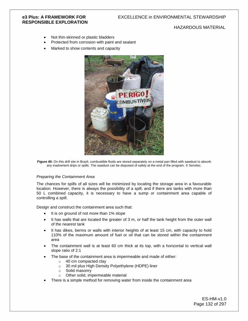
e3 Plus: A FRAMEWORK FOR EXCELLENCE in ENVIRONMENTAL STEWARDSHIP RESPONSIBLE EXPLORATION
HAZARDOUS MATERIAL
ES-HM-v1.0 Page 132 of 297
Not thin-skinned or plastic bladders
Protected from corrosion with paint and sealant
Marked to show contents and capacity
Figure 40: On this drill site in Brazil, combustible fluids are stored separately on a metal pan filled with sawdust to absorb any inadvertent drips or spills. The sawdust can be disposed of safely at the end of the program. © Servitec.
Preparing the Containment Area
The chances for spills of all sizes will be minimized by locating the storage area in a favourable location. However, there is always the possibility of a spill, and if there are tanks with more than 50 L combined capacity, it is necessary to have a sump or containment area capable of controlling a spill. Design and construct the containment area such that:
It is on ground of not more than 1% slope
It has walls that are located the greater of 3 m, or half the tank height from the outer wall of the nearest tank
It has dikes, berms or walls with interior heights of at least 15 cm, with capacity to hold 110% of the maximum amount of fuel or oil that can be stored within the containment area
The containment wall is at least 60 cm thick at its top, with a horizontal to vertical wall slope ratio of 2:1
The base of the containment area is impermeable and made of either: o 40 cm compacted clay o 30 mil plus High Density Polyethylene (HDPE) liner o Solid masonry o Other solid, impermeable material
There is a simple method for removing water from inside the containment area

e3 Plus: A FRAMEWORK FOR EXCELLENCE in ENVIRONMENTAL STEWARDSHIP RESPONSIBLE EXPLORATION
HAZARDOUS MATERIAL
ES-HM-v1.0 Page 133 of 297
Spill kits, fire extinguishers, and first aid kits are available at all storage areas (keep the fire extinguisher no closer than 10 m and no further than 25 m from the containment area)
Make provision to prevent vehicle impacts by using:
Berms
Steel or concrete posts
If there are small amounts of fuel or oil to be stored (e.g. lube oil) which do not require a containment facility or sump, place the storage containers on oil absorbent material, sufficient to immediately capture spills and leakage. Once the storage area is in use, give someone the responsibility of inspecting the storage area and containment facility daily for leaks and spills. Train this person to immediately address any problem he/she sees. This person is also to ensure good housekeeping at the site, by clearing the containment area daily of any trash or plant debris, to lower the fire hazard. Installing and Maintaining Tanks
Once the proper tanks and a containment area to hold them have been identified, the tanks must be installed properly. This will ensure that there is minimal opportunity for fire, rupture or spills, whether the tanks are being filled or discharged. When installing tanks:
Separate tanks by one-sixth the sum of their diameters or 1 m, whichever is greater
Separate fuel or oil tanks from liquefied petroleum gas containers by an even greater distance of at least 6 m
Install all piping with protective coatings or wrappings
Place fill and discharge lines such that they enter tanks only through the top, and so that fill lines are sloped toward the tank
Only install tanks on a foundation of concrete, masonry, piling or steel to minimize settling and prevent corrosion
Use concrete, protected steel or masonry – which are all fire-resistant – as supports to anchor tanks to their foundations, placing them so as to provide an even load distribution, rather than subjecting some small portion of the tank to a high stress load
Put a roof over the tanks in areas of high rainfall, to prevent them from getting wet and corroding
Inspect the tanks and hoses daily for leaks or spills
Inspect tanks internally every 10 years
10.1.2 Use of Drums and Other Containers
For smaller jobs with low fuel requirements, a few 205 L drums or even a few portable 20 L containers might meet storage needs. However, although these are small containers, it is still necessary to take precautions against fire or spills. In the case of 205 L drums (when storage needs are less than 2,000 L) the containment area requirement is the same as for larger storage tanks. Take the following precautions when using drums and smaller containers:
Only use metal drums designed for storage of flammable liquids

e3 Plus: A FRAMEWORK FOR EXCELLENCE in ENVIRONMENTAL STEWARDSHIP RESPONSIBLE EXPLORATION
HAZARDOUS MATERIAL
ES-HM-v1.0 Page 134 of 297
Store 205 L drums on their sides, with the bung halfway up, to ensure that the seal does not dry out and that rainwater will not penetrate the seal
Never put more than 10 of any 205 L fuel drums in the same containment area
If using portable containers, use only those designed to transport flammable liquids and equipped with spouts to prevent spillage while pouring
Where possible, do not use portable containers made of metal that hold more than 20 L, or plastic containers that hold more than 4 L
Avoid stacking containers or drums, but if this is not possible, then place sufficient support between levels, to provide stability and relieve stress on the containers or drums
If placing small containers inside a building or in a locker (which must be well marked), ensure there is adequate ventilation to remove the risk of vapour buildup
If fuel and oil storage needs are for less than 50 L, place the containers holding the liquids on impermeable or oil absorbent material. For drums or other containers which in sum hold more than 50 L of fuel or oil, refer to the section on Containment Areas
10.1.3 Refuelling Operations
Any time fuel or oil is moved from one tank to another, or from a small container (e.g., an oil can), there is the risk of spillage and fire. Preventive measures must be taken against spills, even when doing something as simple as pouring oil into a crankcase. Use a funnel, and be sure the vehicle or motor being serviced is on an oil absorbent mat or an impermeable foundation. There are bigger risks when pumping larger quantities of fuel. Some preventive measures to lower risk are:
Only refuel at designated locations
Always have operators stop their engines and get out of their vehicles or aircraft during fuelling
Clearly post signs prohibiting smoking and open flames in areas used for fuelling
Ensure that the dispensing hoses do not exceed 15 m in length
If using powered dispensing nozzles, they should be of the automatic-closing type, with devices (e.g. a switch or circuit breaker) to shut off the power in an emergency
Mount dispensing devices (e.g. pumps) on a concrete island, or ensure they are buffered by steel anti-collision posts
If there is a spill during fuelling, replace the filler caps on the vehicle and clean up spillage before starting the engine. Liquid fuels and oils that cannot be handled by pump should be in portable containers with pouring spouts, to minimize the chance of spillage. There is a major risk of igniting vapours through static discharge, when loading and unloading large tank vehicles. While the risk is less with fuelling smaller vehicles, there is still a risk, so while pumping flammable liquids, take the following precautions:
Post prominent "No Smoking" signs at the fuelling location.
When loading or unloading tankers and other large vehicles, provide protection against static sparking by connecting a wire from the pump to the tank being filled. This can be easily facilitated by permanently connecting one end of a metal wire to the fill stem, or to some metal part of the fuel rack structure. Then, prior to pumping fuel, the operator connects the other end of the wire to some metal part of the vehicle being filled. Attach a clamp to the free end of the wire, to make this easier for the operator.

e3 Plus: A FRAMEWORK FOR EXCELLENCE in ENVIRONMENTAL STEWARDSHIP RESPONSIBLE EXPLORATION
HAZARDOUS MATERIAL
ES-HM-v1.0 Page 135 of 297
If pumping to a small vehicle, make sure that, prior to touching the pump handle at any time, static is released by touching metal away from the pump handle or vehicle tank. Alternatively, a grounding wire can be used, as discussed above.
10.1.4 Transporting Fuel and Petroleum Products
The greatest chance of a serious fire or uncontrollable spill exists from even a minor accident, when transporting fuel or oils. The best preventive measure is to use well-trained and rested drivers. Some additional precautions to observe are:
When moving small amounts of fuel or oil, use only portable tanks or cans that are made of metal or approved plastic, which have tight closures with screw or spring covers, and which are equipped with spouts or other means to allow pouring without spilling
Never use leaking tanks or containers to transport fuel or oil
Secure fuel tanks to prevent slipping or rotating, or fuel tanks being jarred loose
Place fuel tanks and cans on the vehicle so as to minimize the chance that an impact would cause them to rupture (e.g. do not mount a gas can on the rear of a vehicle)
Make sure that if a fuel can is placed in a compartment on a vehicle, that the compartment is vented
Place tanks and cans with fuel in locations on the vehicle where there is minimum exposure to heat
If it is necessary to place the fuel container near an engine or exhaust system, shield the container against the heat
10.1.5 Handling Fuels and Oils on Water
Since any spillage of fuel or oil is difficult to contain when working on water or ice, it is necessary to take special precautions in these situations. When drilling on ice:
Park vehicles and equipment off the ice if possible
If parking on the ice, place oil absorbent mats below each vehicle
Make daily inspections for leaks and spillage
When drilling from a barge:
Have a company representative who is capable of dealing with a spill, present during refuelling or oil changes
Transport fuel to the barge in clean, sealed containers on a service vessel capable of containing any spill
Transfer fuel to the barge using a hose enclosed within another hose
Make sure the barge has a "lip" and collection tanks, to prevent fluids on deck from escaping into the water
Store fuel below decks or in double-walled tanks
Anchor an oil absorbent boom around the barge at all times
Have the boom towed by a separate boat and readily available during moves
e3 Plus: A FRAMEWORK FOR EXCELLENCE in ENVIRONMENTAL STEWARDSHIP RESPONSIBLE EXPLORATION
HAZARDOUS MATERIAL
ES-HM-v1.0 Page 136 of 297
10.2 Propane and Other Liquefied Petroleum Gases
Liquefied Petroleum (LP) gases are Class IA liquids, highly flammable, and require precautionary measures. These gases include:
Propane
Propylene
Butane
Butylene
The precautionary measures discussed here apply to propane (the most common member of the family), but they apply equally to the other flammable liquefied gases. When using propane:
Make sure there is adequate ventilation during use or for storage.
Only use propane that has been odorized, with an agent of such character as to indicate positively (e.g. by distinct odour) the presence of propane gas. Technically, the odour must be noticeable at a propane gas concentration in the air of not over one-fifth the lower limit of flammability.
Ensure that, when in use, propane tanks and their first stage regulating equipment are located outside, not within, buildings.
When storing propane:
Do not store tanks of 500 L to 2,000 L less than 10 m apart. Smaller tanks may be placed adjacent to each other.
Do not place tanks that are installed for use on top of each other.
Transport and store propane tanks in an upright position, with valves closed and capped.
Secure propane tanks in place with brackets or straps.
Separate propane cylinders from cylinders with oxidants (e.g., oxygen).
If a tank or cylinder valve freezes, thaw it in warm air or water and dry. Do not try to thaw valves in high heat or with an open flame.
Move a leaking tank away from anything flammable. As part of general good housekeeping, clear areas around tanks to keep them clear of weeds, long dry grass or rubbish that could easily burn.
10.3 Explosives
Explosives used in the field are defined as those products specifically designed to create a useable force, through an almost instantaneous high-speed chemical reaction. Explosive articles (e.g., blasting agents, ammunition, explosives, detonators, fuses) contain one or more explosive substances. Explosives are frequently required for blasting in exploration to:
Build roads and drill pads
Excavate trenches or pits
Open exploration adits In addition, there may be instances where explosives are used to free stuck drill rods.

e3 Plus: A FRAMEWORK FOR EXCELLENCE in ENVIRONMENTAL STEWARDSHIP RESPONSIBLE EXPLORATION
HAZARDOUS MATERIAL
ES-HM-v1.0 Page 137 of 297
Always use extreme caution in handling, transporting, storing, and disposing of explosives. It is important to recognize that all of them have varying degrees of sensitivity, stability, and toxicity. Never treat any explosive material as a toy. Although the science of manufacturing explosives has advanced considerably, there is still an element of unpredictability in their behaviour. Ensure that any persons using explosives in exploration programs are properly trained and licensed professionals, who are fully qualified for the specific explosive materials to be used and the job required. Most jurisdictions have regulations that apply to explosives transport, storage, and use. It is important to be aware of, and abide by, the applicable regulations and acquire the necessary permits for explosives use.
10.3.1 Transport and Storage of Explosives
The transport and storage of explosives is commonly governed by regulations and the conditions of explosives permits. Companies must ensure that they and their field crews are familiar with these regulations and conditions and abide by them. When transporting or moving explosive materials, always take the following precautions:
Do not transport explosives, blasting agents, and blasting supplies with other materials
Never leave a vehicle transporting explosives unattended
Transport blasting caps (including electric) in a different vehicle from other explosives
Use vehicles for transporting explosives that are in good mechanical condition, and sturdy enough to carry the load without difficulty
When using an open-bodied vehicle for transport, mount the original manufacturer‟s container for transporting the explosives securely to the vehicle bed
Check that the vehicle has tight floors, and that the container holding explosives cannot be exposed to any sparks, whatever the source or cause
Equip all vehicles transporting explosives with a fully-charged fire extinguisher that is in good condition, and verify that the driver is trained in using the extinguisher
Remove explosives, blasting agents or blasting supplies from a motor vehicle before taking the vehicle into a garage or shop for repairs or servicing
When storing explosives:
Store blasting caps, detonating primers and primed cartridges in a separate magazine from other explosives or blasting agents
Enforce a ban on smoking and open flames within 15 m of explosives and detonator storage magazines
Powder Magazines
You must keep all explosives in storage facilities which are
Properly constructed
Secured, and
Barricaded You must ensure that these facilities, generally termed "magazines", are always under the supervision of a responsible person with the authority to enforce safety precautions.

e3 Plus: A FRAMEWORK FOR EXCELLENCE in ENVIRONMENTAL STEWARDSHIP RESPONSIBLE EXPLORATION
HAZARDOUS MATERIAL
ES-HM-v1.0 Page 138 of 297
Specifications for your magazines depend on the quantity of explosives you will be storing. There are two classes of magazines and you will generally need at least 1 of each type, as outlined below:
Class I magazines are usually required because this is the class of facility needed to store more than 20kg of explosives and if you are using explosives you will likely have at least this much.
Class II magazines have less stringent specifications, are small enough to easily moved, and are for storing explosives when you have less than 20kg of material. These are generally sufficient for storing your blasting caps and primer cord, which you always keep, separated from the primary explosives.
Class II magazines are also frequently used for very short-term storage near the site where they will be used. In this case the magazine must be placed at least 50 metres away from the work area. Class I magazines are always in separate structures while Class II magazines may be placed inside warehouses if placed not more than 3 metres from a door to the outside at ground level.
In all other cases in sitting your magazines you should:
Clearly post the area with "Danger Explosives" or similar signs.
Ensure that the ground around the magazine slopes away from it.
Keep the area around the magazine clear of brush and dried vegetation for a distance of at least 10 metres
Separate magazines with barricades and the following minimum distances depending on the amount of explosives to be stored:
6 metres apart for up to 50kg of explosives 10 metres of apart for 51 to 500kg of explosives 30 metres of apart for 501 to 5000kg of explosives
You must be sure you have proper barricades not just between magazines, but also between magazines and buildings, highways and railways. A barricade can be:
Natural in the form of a dense stand of tree or hill
Manmade and constructed if dirt or rocks with a width of at least 1 metre along its entire length
Your barricades around a magazine must be of such a height that it is impossible to see from the top of the magazine the adjacent:
Magazine,
Building,
Highway, or
Railway.
You should construct your magazines such that they are:
Bullet resistant,
Fire resistant,
Weather resistant, and
Ventilated. If they are heated, this should be with hot-water radiators located such that no part of the radiator can come into contact with explosives. They should be lit by electric safety flashlights or electric safety lanterns.

e3 Plus: A FRAMEWORK FOR EXCELLENCE in ENVIRONMENTAL STEWARDSHIP RESPONSIBLE EXPLORATION
HAZARDOUS MATERIAL
ES-HM-v1.0 Page 139 of 297
Additionally, you should construct your Class I magazines with:
Walls of masonry, wood, or metal with the outer and inner walls separated by at least 20cm filled with sand or bricks.
A covering of galvanized sheet metal or aluminium on the outer wall if that wall is made of wood.
Sand trays covering the entire surface of the roof except for an anti-spark screened opening for ventilation.
Floors of wood which are placed on a substantial foundation.
A door of the minimum size to permit entry and exit with explosives and which you can secure to prevent unauthorized persons from getting into the magazine.
In the case of Class II magazines, your construction can be with wood or metal. You should:
Make your wood magazines with 5cm thick hardwood, well braced and covered with sheet metal, and countersink all nails in the interior.
Line metal magazines with 1cm thick plywood and a cover that overlaps the sides by 2cm.
Put strong hinges on the covers and install latches that you can lock.
Clearly mark the magazines on all sides with "Explosives -Keep Fire Away".
Install wheels or casters for easy removal in case of fire if you plan on putting the magazine in a warehouse.
Within the magazine you should
Place packages of explosives flat with the topside up.
Not stack the explosives against the wall.
Separate black powder from your other explosives, and stand black powder kegs on end with the bung side down or on their sides with the seam side down.
Group your explosives by type to minimize confusion on what is being used.
Always use the oldest explosives first.
Never unpack or repack explosives inside the magazine.
Never use tools in the magazine that could cause sparks. If you think you have deteriorated or unstable explosives (for example you see leaks of any type), you should immediately contact an expert to remove and destroy the suspect explosives.
10.3.2 Handling of Fuses and Blasting Caps
Materials used to initiate a blast have the potential to do serious harm. They must be treated with the same respect as the explosives themselves. When working with fuses, observe the following guidelines:
only use safety fuses where sources of extraneous electricity make the use of electric blasting caps dangerous
Never use a fuse that has been hammered or injured in any way
Do not hang a fuse on nails or other projections, as this will cause a sharp bend in the fuse
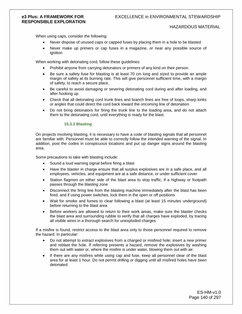
e3 Plus: A FRAMEWORK FOR EXCELLENCE in ENVIRONMENTAL STEWARDSHIP RESPONSIBLE EXPLORATION
HAZARDOUS MATERIAL
ES-HM-v1.0 Page 140 of 297
When using caps, consider the following:
Never dispose of unused caps or capped fuses by placing them in a hole to be blasted
Never make up primers or cap fuses in a magazine, or near any possible source of ignition
When working with detonating cord, follow these guidelines:
Prohibit anyone from carrying detonators or primers of any kind on their person.
Be sure a safety fuse for blasting is at least 70 cm long and sized to provide an ample margin of safety at its burning rate. This will give personnel sufficient time, with a margin of safety, to reach a secure place.
Be careful to avoid damaging or severing detonating cord during and after loading, and after hooking up.
Check that all detonating cord trunk lines and branch lines are free of loops, sharp kinks or angles that could direct the cord back toward the oncoming line of detonation
Do not bring detonators for firing the trunk line to the loading area, and do not attach them to the detonating cord, until everything is ready for the blast.
10.3.3 Blasting
On projects involving blasting, it is necessary to have a code of blasting signals that all personnel are familiar with. Personnel must be able to correctly follow the intended warning of the signal. In addition, post the codes in conspicuous locations and put up danger signs around the blasting area. Some precautions to take with blasting include:
Sound a loud warning signal before firing a blast
Have the blaster in charge ensure that all surplus explosives are in a safe place, and all employees, vehicles, and equipment are at a safe distance, or under sufficient cover
Station flagmen on either side of the blast area to stop traffic, if a highway or footpath passes through the blasting zone
Disconnect the firing line from the blasting machine immediately after the blast has been fired, and if using power switches, lock them in the open or off positions
Wait for smoke and fumes to clear following a blast (at least 15 minutes underground) before returning to the blast area
Before workers are allowed to return to their work areas, make sure the blaster checks the blast area and surrounding rubble to verify that all charges have exploded, by tracing all visible wires in a thorough search for unexploded charges
If a misfire is found, restrict access to the blast area only to those personnel required to remove the hazard. In particular:
Do not attempt to extract explosives from a charged or misfired hole; insert a new primer and reblast the hole. If referring presents a hazard, remove the explosives by washing them out with water or, where the misfire is under water, blowing them out with air.
If there are any misfires while using cap and fuse, keep all personnel clear of the blast area for at least 1 hour. Do not permit drilling or digging until all misfired holes have been detonated.

e3 Plus: A FRAMEWORK FOR EXCELLENCE in ENVIRONMENTAL STEWARDSHIP RESPONSIBLE EXPLORATION
HAZARDOUS MATERIAL
ES-HM-v1.0 Page 141 of 297
10.4 Solvents and Paints
It is necessary to inform employees about any hazardous chemicals they are working with, including solvents and even paint. Employees need to be trained to work safely with these chemicals, and to know about the hazards that are involved with their use.
When toxic solvents and paints are used, take 1 or more of the following measures to safeguard the health of employees exposed to these chemicals:
Use the safest solvent available for the job, one that is the least toxic and least flammable. Better yet, find a water-based or solvent-free substitute. In particular, avoid methylene chloride strippers for paint removal, as breathing methylene chloride can damage the central nervous system, and contact with eyes or skin can result in burns.
Use the smallest amount of solvent that will get the job done. The intent should be to not store any solvents, but if solvent storage is necessary, make the amount minimal.
Ensure that employees do not have access to solvents to wash their hands; solvents can clean difficult stains from skin, but only at great risk. Provide a waterless cleaner, soap or detergent - anything but solvent, as none are safe for the skin.
Use solvent-resistant gloves, aprons or goggles when using solvents and paints, to prevent contact with eyes and skin.
If clothes get wet with solvent, remove them and wash them with soap or detergent.
When storing solvents:
Store solvents and paints in clearly labelled containers that have been well secured against spillage and which are designed for flammable materials
Eliminate the risk of having solvent-soaked rags combust spontaneously by storing them in closed containers designed specifically for such materials. Do the same with waste solvent.
Clean up spills immediately, and keep the workplace tidy.
Vapours can reach dangerous concentrations in areas of restricted air circulation, so take the following precautions:
Work with solvents and paints only with good ventilation. This means getting fumes and vapours out of the work area, not just moving them around with fans. If a fan is needed to move fumes out of the work area, make sure it is turned on and in good working order.
Make sure there are no open flames (e.g., pilot lights) on appliances when working with solvent-based paints. These could ignite fumes from the solvent, even in a ventilated building.
Never enter a tank, vat or closed space that may be contaminated with solvent. Sudden death can occur from poisoning, explosion or lack of oxygen.
Never smoke or do hot work near solvents or solvent vapours, even if the solvents are non-flammable. Non-flammable chlorinated solvents create very toxic fumes (e.g., phosgene) when heated.
Dirty or used solvent is hazardous waste that needs to be labelled and stored properly (see storage of solvents above). Dispose of this waste solvent properly - never pour it into plumbing fixtures or on the ground.

e3 Plus: A FRAMEWORK FOR EXCELLENCE in ENVIRONMENTAL STEWARDSHIP RESPONSIBLE EXPLORATION
HAZARDOUS MATERIAL
ES-HM-v1.0 Page 142 of 297
10.5 Drilling Fluids
Drilling fluids can be stored on a metal pan filled with wood chips to absorb any drips and spills. The chips can be disposed of safely at the end of the drilling. Drilling fluids (drilling muds) of various types are used in all drilling operations, to carry drill cuttings up the hole, improve recoveries, lubricate the drill string and drill bit, and prevent lost circulation. There are 4 principal types of drill fluids:
Air blast
Water-based
Oil-based
Synthetic-based
For purely technical reasons, oil-based fluids are superior to water or synthetic-based fluids. However, most mineral exploration programs, whether they use diamond, mud-rotary, or air blast drill methods, will have good performance with water-based fluids. Avoid oil-based and synthetic-based drill fluids and other petroleum products, such as:
Diesel
Petroleum-based rod grease
Solvents It is the company‟s responsibility to obtain data from the drill fluid supplier, to determine drill fluid suitability and provide proof that liquid or powdered additives are not harmful to animals, plants or the groundwater.
Figure 41: Note the pan filled with wood chips underneath the rig on this drill site in Brazil. Inadvertent drips and spills are absorbed by the wood chips and can be disposed of safely. © Servitec.

e3 Plus: A FRAMEWORK FOR EXCELLENCE in ENVIRONMENTAL STEWARDSHIP RESPONSIBLE EXPLORATION
HAZARDOUS MATERIAL
ES-HM-v1.0 Page 143 of 297
Figure 42: Drilling fluids on this project in Brazil are stored on a metal pan filled with wood chips to absorb any drips and spills. The chips can be disposed of safely at the end of the drilling. © Servitec.
10.5.1 Handling and Storage of Drilling Fluids
It is important to be aware that exposure to drilling fluids and additives may be harmful to a person‟s health. While the drilling contractor will generally be responsible for preparation of an additive package, there are circumstances in which the company may be required to assist in that process. If this is the case:
Use a respirator, goggles, gloves, and an apron when working with dry additives for drilling fluids
Use special care when handling additives such as caustic soda that may cause severe burning or injury in minor amounts
Store liquid additives such as industrial chemicals with good ventilation
Handle each additive as recommended by the manufacturer, especially when labelled as hazardous
Avoid skin contact with additives or inhalation of fumes emanating from additives These measures are those that the drilling contractor and his employees should already be taking. It is the company‟s responsibility to inform the contractor if, in the company‟s opinion, there is a risk to health or safety due to the manner in which the contractor or the contractor‟s employees are preparing drilling additives. As a general rule, ensure that recovered drill fluid returns to the mud sump for re-injection.

e3 Plus: A FRAMEWORK FOR EXCELLENCE in ENVIRONMENTAL STEWARDSHIP RESPONSIBLE EXPLORATION
HAZARDOUS MATERIAL
ES-HM-v1.0 Page 144 of 297
10.6 Pesticides and Herbicides
Pesticides and herbicides are rarely used in exploration, except perhaps in very small amounts. These chemicals can be highly toxic, so explicitly follow the special storage and handling precautions recommended by the manufacturer. While this section addresses use of pesticides to treat areas outdoors, observe precautions even with minor pesticide application inside buildings.
Pesticides are typically used to control:
Mosquitoes (particularly where there is a risk of malaria)
Ticks
Cockroaches
Rodents
Other disease-causing organisms
Time is critical with any pesticide poisoning. Become familiar with the symptoms of pesticide poisoning, which are often documented on pesticide containers. If anyone is poisoned, get immediate help from a local hospital, physician or the nearest poison control centre.
10.6.1 Handling and Storage of Pesticides and Herbicides
Given the often highly toxic nature of pesticides and herbicides, it is necessary to take precautions in their presence. Never use, transport or store the following, which are especially dangerous pesticides:
DDT
Aldrin
Chlorodecone
Dieldrin
Endrin When working with pesticides and herbicides:
Do not clean equipment used with pesticides and herbicides near any water supply
Do not store any pesticide or herbicide where it may come into contact with food
Never dispose of any pesticide or herbicide in a plumbing fixture Where possible, only store pesticides and herbicides in a room:
With no drains
With good ventilation
Secured with a lock Never reuse a pesticide container for anything else, except as recommended by the manufacturer.
10.7 Acids and Bases
The handling and storage of caustic materials requires particular care. Caustic materials commonly used for exploration activities include hydrofluoric acid, hydrochloric acid and caustic
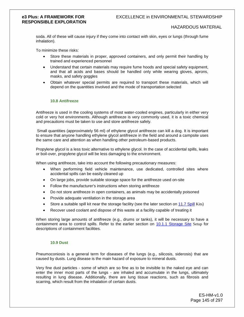
e3 Plus: A FRAMEWORK FOR EXCELLENCE in ENVIRONMENTAL STEWARDSHIP RESPONSIBLE EXPLORATION
HAZARDOUS MATERIAL
ES-HM-v1.0 Page 145 of 297
soda. All of these will cause injury if they come into contact with skin, eyes or lungs (through fume inhalation). To minimize these risks:
Store these materials in proper, approved containers, and only permit their handling by trained and experienced personnel
Understand that certain materials may require fume hoods and special safety equipment, and that all acids and bases should be handled only while wearing gloves, aprons, masks, and safety goggles
Obtain whatever special permits are required to transport these materials, which will depend on the quantities involved and the mode of transportation selected
10.8 Antifreeze
Antifreeze is used in the cooling systems of most water-cooled engines, particularly in either very cold or very hot environments. Although antifreeze is very commonly used, it is a toxic chemical and precautions must be taken to use and store antifreeze safely. Small quantities (approximately 56 ml) of ethylene glycol antifreeze can kill a dog. It is important to ensure that anyone handling ethylene glycol antifreeze in the field and around a campsite uses the same care and attention as when handling other petroleum-based products. Propylene glycol is a less toxic alternative to ethylene glycol. In the case of accidental spills, leaks or boil-over, propylene glycol will be less damaging to the environment. When using antifreeze, take into account the following precautionary measures:
When performing field vehicle maintenance, use dedicated, controlled sites where accidental spills can be easily cleaned up
On large jobs, provide suitable storage space for the antifreeze used on-site
Follow the manufacturer's instructions when storing antifreeze
Do not store antifreeze in open containers, as animals may be accidentally poisoned
Provide adequate ventilation in the storage area
Store a suitable spill kit near the storage facility (see the later section on 11.7 Spill Kits)
Recover used coolant and dispose of this waste at a facility capable of treating it When storing large amounts of antifreeze (e.g., drums or tanks), it will be necessary to have a containment area to control spills. Refer to the earlier section on 10.1.1 Storage Site Setup for descriptions of containment facilities.
10.9 Dust
Pneumoconiosis is a general term for diseases of the lungs (e.g., silicosis, siderosis) that are caused by dusts. Lung disease is the main hazard of exposure to mineral dusts. Very fine dust particles - some of which are so fine as to be invisible to the naked eye and can enter the inner most parts of the lungs - are inhaled and accumulate in the lungs, ultimately resulting in lung disease. Additionally, there are lung tissue reactions, such as fibrosis and scarring, which result from the inhalation of certain dusts.
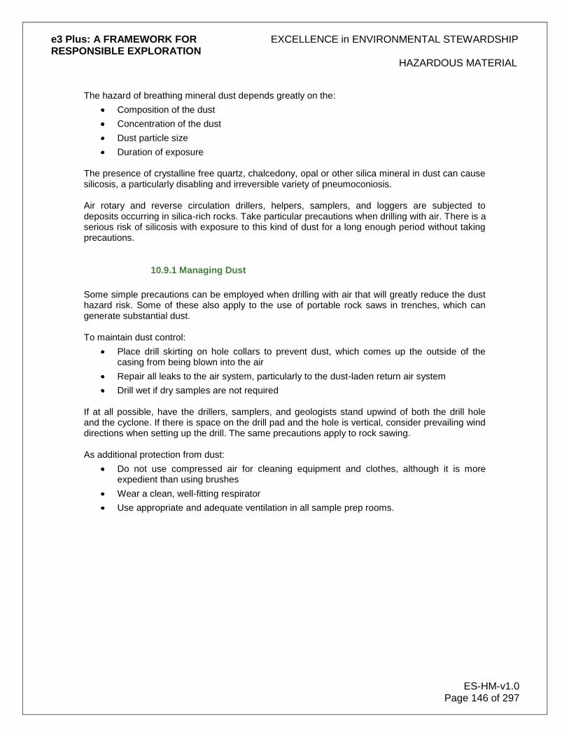
e3 Plus: A FRAMEWORK FOR EXCELLENCE in ENVIRONMENTAL STEWARDSHIP RESPONSIBLE EXPLORATION
HAZARDOUS MATERIAL
ES-HM-v1.0 Page 146 of 297
The hazard of breathing mineral dust depends greatly on the:
Composition of the dust
Concentration of the dust
Dust particle size
Duration of exposure The presence of crystalline free quartz, chalcedony, opal or other silica mineral in dust can cause silicosis, a particularly disabling and irreversible variety of pneumoconiosis. Air rotary and reverse circulation drillers, helpers, samplers, and loggers are subjected to deposits occurring in silica-rich rocks. Take particular precautions when drilling with air. There is a serious risk of silicosis with exposure to this kind of dust for a long enough period without taking precautions.
10.9.1 Managing Dust
Some simple precautions can be employed when drilling with air that will greatly reduce the dust hazard risk. Some of these also apply to the use of portable rock saws in trenches, which can generate substantial dust. To maintain dust control:
Place drill skirting on hole collars to prevent dust, which comes up the outside of the casing from being blown into the air
Repair all leaks to the air system, particularly to the dust-laden return air system
Drill wet if dry samples are not required
If at all possible, have the drillers, samplers, and geologists stand upwind of both the drill hole and the cyclone. If there is space on the drill pad and the hole is vertical, consider prevailing wind directions when setting up the drill. The same precautions apply to rock sawing. As additional protection from dust:
Do not use compressed air for cleaning equipment and clothes, although it is more expedient than using brushes
Wear a clean, well-fitting respirator
Use appropriate and adequate ventilation in all sample prep rooms.

e3 Plus: A FRAMEWORK FOR EXCELLENCE in ENVIRONMENTAL STEWARDSHIP RESPONSIBLE EXPLORATION
SPILL MANAGEMENT
ES-SM-v1.0 Page 147 of 297
11.0 Spill Management
Spills have the potential to cause severe environmental damage as well as considerable economic and image consequences for a company. Workers must ensure that any spills are treated with great care, and dealt with promptly, to minimize the possibility of any of them becoming a major issue. The principal objectives of this 11.0 Spill Management section are to:
Provide readily accessible emergency information to the cleanup crews, company management and government agencies, in the event of a spill
Comply with the company's environmental and crisis management policies
Comply with national and local regulations and guidelines pertaining to the preparation of contingency plans and notification requirements
Promote the safe and effective recovery of spilled materials
Minimize the environmental impacts of spills to water or land
Facilitate the management of wastes according to environmental legislation It is very important to place a strong emphasis on the avoidance of spills. Information on this subject is provided in the sections dealing with the management of 10.0 Hazardous Material. Prominently post, in several locations, a list of coordinates for those to contact, and in what order, in the event of a spill. Petroleum-based products are used in almost all exploration projects. Since these products are the most common hazardous materials at exploration sites, and are often present in large quantities, the non-material specific information in this section is geared toward helping deal with spills of petroleum products (typically diesel-type fuels). Spill mitigation techniques for non-petroleum-based hazardous materials (e.g., antifreeze, sewage) are covered in the 11.3.1 Material Specific subsection below. Much of the information provided here is intended to cover situations up to and including large spills. Information is included on dealing with small spills where appropriate. Scale the level of organization and planning for spill mitigation to the size of the project and the amount of fuel stored at the exploration site. Scale the amount and type of spill response equipment accordingly as well. Many exploration activities are carried out by companies or individuals under contract to the exploration company. It is important that the exploration company ensures that contractors are fully aware of the company's spill response plan, and that appropriate contractors are involved in reporting, mitigation, and documentation of spills.
11.1 Definition
Legal spill definitions vary depending on material, jurisdiction, and environment. This section deals mainly with petroleum products, as they are utilized in most exploration programs. Other hazardous materials in significant quantities are more likely encountered with mining projects. Spill definitions vary, depending on whether a spill takes place on water, land, or ice. Always be aware of, and abide by, local regulations.

e3 Plus: A FRAMEWORK FOR EXCELLENCE in ENVIRONMENTAL STEWARDSHIP RESPONSIBLE EXPLORATION
SPILL MANAGEMENT
ES-SM-v1.0 Page 148 of 297
The practical thresholds for significant (reportable) spills of petroleum products are as follows:
Land-based spills: 70 L
Spills on water: Any amount
Spills on snow/ice: If spillage can be recovered before it enters a waterway, use the land-based threshold above (70 L); otherwise report any spillage
Report any spillage of the following non-hydrocarbon materials:
Toxic substances (e.g., solvents, antifreeze)
Contaminated water
Sewage Report any spill that results in human injury or loss of wildlife. All spills should be cleaned up regardless of size as part of regular maintenance. Reporting a spill is good business practice and can protect the company. By reporting small spills and establishing and maintaining a good relationship with regulatory bodies, the company has a better chance of not being blamed for unreported spills, small or large, for which the company is not responsible. Some jurisdictions require that probable spills (where it is uncertain if a spill actually occurred) be reported. Keep in mind that using contractors for activities such as surveys, trenching, and drilling does not absolve the company of responsibility for spills.
11.2 Planning
Planning is essential to successful spill response operations. Create a response structure that is appropriately scaled to the size of the exploration project. Proper planning is needed to ensure that:
Personnel responding to spills know their respective roles
Personnel respond to spills in a safe manner
Spills are dealt with on a timely basis
The proper mitigation technique is used
The spill and mitigation efforts are well documented and reported
As an integral part of planning:
Develop a response plan suited to spill scenarios applicable to the exploration project
Document this plan and ensure that spill responders are familiar with it
Solicit suggestions from staff familiar with local conditions
Review plans on a regular basis, or when the scope of the project changes It is also a good idea to practice responding to various spill scenarios that may occur at exploration sites.

e3 Plus: A FRAMEWORK FOR EXCELLENCE in ENVIRONMENTAL STEWARDSHIP RESPONSIBLE EXPLORATION
SPILL MANAGEMENT
ES-SM-v1.0 Page 149 of 297
11.2.1 Public
Assign a Spill Team Leader to be the sole contact with the local public during any spill incident. In a small company, this may be you, but you may be able to delegate this role in a larger organization. All communication with the public should, however, be coordinated with your corporate head office. Your Spill Team Leader will assess the potential impact of a spill on the public and will communicate as required (for example, directly to the local fire department, if there is one) to ensure the safety of all concerned.
11.2.2 Responsibilities
This section provides guidelines for Spill Response Team organization. These cover situations up to and including large exploration projects. You should scale duties and responsibilities to the size of the project. Smaller projects will require individuals to cover multiple roles. You should document the duties and responsibilities of the following:
First Person On-Scene,
Spill Response Team, and
Spill Response Team Leader. You should identify and list those individuals who are designated as potential Team Leaders and members of the Spill Response Team. Their individual responsibilities are outlined below. First Person on-Scene
If you are the First Person On-Scene, you should take the following steps:
1. Assess the initial severity of the spill and safety and environmental concerns.
2. Identify the source of the spill.
3. Determine the size of the spill and stop or contain it, if possible.
4. Notify the Spill Response Team Leader.
5. Immediately stop work, transfer or fuelling operations, control all sources of ignition.
6. If possible and safe to do so, put out any fire and stop any leak that may be present.
7. If possible, prevent access of spilled material to water. Team Leader
As Spill Response Team Leader, you should
1. Ensure that all safety measures are taken for the preservation and protection of human life.
2. Identify potential fire hazards and request standby or response from the Fire Response Team.
3. When safe to do so, ensure that the source of the spill is secured.
4. Notify additional trained Spill Response Team personnel, if required.
5. Restrict further operations that may interfere with a sustained response to the spill incident.
6. Evaluate the size of the response to be initiated and make assessments relating to the necessity of calling out response contractors.
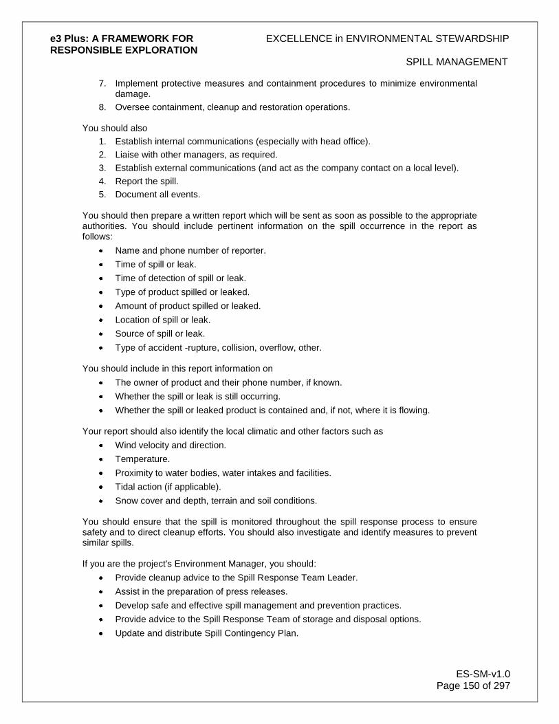
e3 Plus: A FRAMEWORK FOR EXCELLENCE in ENVIRONMENTAL STEWARDSHIP RESPONSIBLE EXPLORATION
SPILL MANAGEMENT
ES-SM-v1.0 Page 150 of 297
7. Implement protective measures and containment procedures to minimize environmental damage.
8. Oversee containment, cleanup and restoration operations. You should also
1. Establish internal communications (especially with head office).
2. Liaise with other managers, as required.
3. Establish external communications (and act as the company contact on a local level).
4. Report the spill.
5. Document all events. You should then prepare a written report which will be sent as soon as possible to the appropriate authorities. You should include pertinent information on the spill occurrence in the report as follows:
Name and phone number of reporter.
Time of spill or leak.
Time of detection of spill or leak.
Type of product spilled or leaked.
Amount of product spilled or leaked.
Location of spill or leak.
Source of spill or leak.
Type of accident -rupture, collision, overflow, other. You should include in this report information on
The owner of product and their phone number, if known.
Whether the spill or leak is still occurring.
Whether the spill or leaked product is contained and, if not, where it is flowing. Your report should also identify the local climatic and other factors such as
Wind velocity and direction.
Temperature.
Proximity to water bodies, water intakes and facilities.
Tidal action (if applicable).
Snow cover and depth, terrain and soil conditions. You should ensure that the spill is monitored throughout the spill response process to ensure safety and to direct cleanup efforts. You should also investigate and identify measures to prevent similar spills. If you are the project's Environment Manager, you should:
Provide cleanup advice to the Spill Response Team Leader.
Assist in the preparation of press releases.
Develop safe and effective spill management and prevention practices.
Provide advice to the Spill Response Team of storage and disposal options.
Update and distribute Spill Contingency Plan.
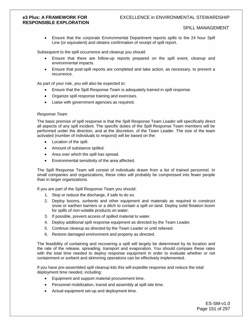
e3 Plus: A FRAMEWORK FOR EXCELLENCE in ENVIRONMENTAL STEWARDSHIP RESPONSIBLE EXPLORATION
SPILL MANAGEMENT
ES-SM-v1.0 Page 151 of 297
Ensure that the corporate Environmental Department reports spills to the 24 hour Spill Line (or equivalent) and obtains confirmation of receipt of spill report.
Subsequent to the spill occurrence and cleanup you should:
Ensure that there are follow-up reports prepared on the spill event, cleanup and environmental impacts.
Ensure that post-spill reports are completed and take action, as necessary, to prevent a recurrence.
As part of your role, you will also be expected to:
Ensure that the Spill Response Team is adequately trained in spill response.
Organize spill response training and exercises.
Liaise with government agencies as required.
Response Team
The basic premise of spill response is that the Spill Response Team Leader will specifically direct all aspects of any spill incident. The specific duties of the Spill Response Team members will be performed under the direction, and at the discretion, of the Team Leader. The size of the team activated (number of individuals to respond) will be based on the:
Location of the spill.
Amount of substance spilled.
Area over which the spill has spread.
Environmental sensitivity of the area affected. The Spill Response Team will consist of individuals drawn from a list of trained personnel. In small companies and organizations, these roles will probably be compressed into fewer people than in larger organizations. If you are part of the Spill Response Team you should:
1. Stop or reduce the discharge, if safe to do so.
2. Deploy booms, sorbents and other equipment and materials as required to construct snow or earthen barriers or a ditch to contain a spill on land. Deploy solid flotation boom for spills of non-volatile products on water.
3. If possible, prevent access of spilled material to water.
4. Deploy additional spill response equipment as directed by the Team Leader.
5. Continue cleanup as directed by the Team Leader or until relieved.
6. Restore damaged environment and property as directed. The feasibility of containing and recovering a spill will largely be determined by its location and the rate of the release, spreading, transport and evaporation. You should compare these rates with the total time needed to deploy response equipment in order to evaluate whether or not containment or sorbent and skimming operations can be effectively implemented. If you have pre-assembled spill cleanup kits this will expedite response and reduce the total deployment time needed, including:
Equipment and support material procurement time.
Personnel mobilization, transit and assembly at spill site time.
Actual equipment set-up and deployment time.
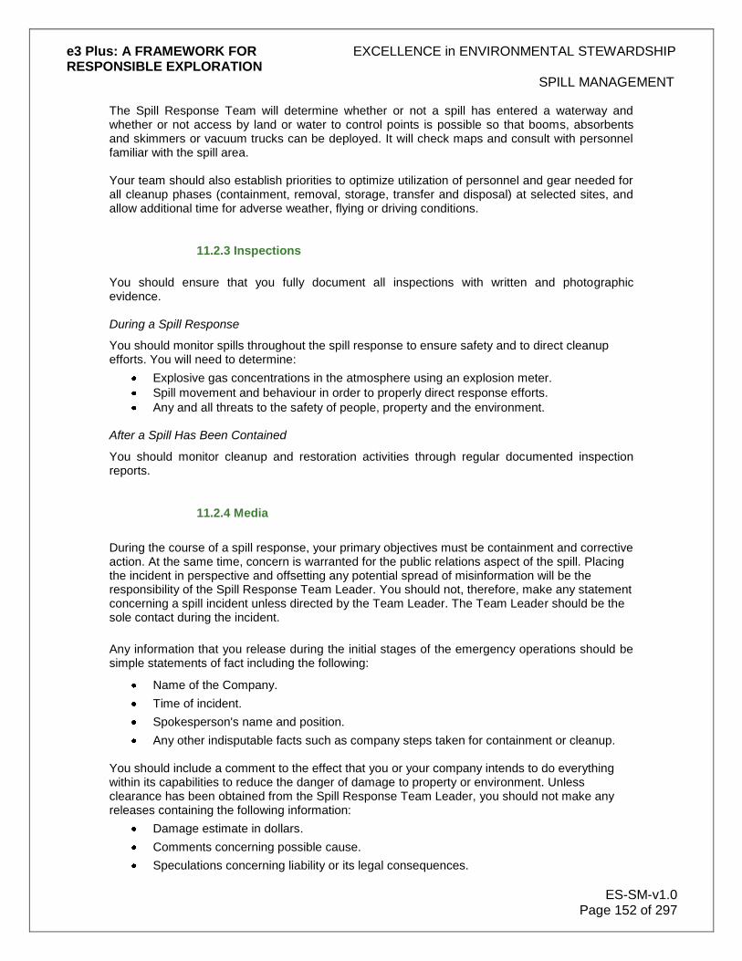
e3 Plus: A FRAMEWORK FOR EXCELLENCE in ENVIRONMENTAL STEWARDSHIP RESPONSIBLE EXPLORATION
SPILL MANAGEMENT
ES-SM-v1.0 Page 152 of 297
The Spill Response Team will determine whether or not a spill has entered a waterway and whether or not access by land or water to control points is possible so that booms, absorbents and skimmers or vacuum trucks can be deployed. It will check maps and consult with personnel familiar with the spill area. Your team should also establish priorities to optimize utilization of personnel and gear needed for all cleanup phases (containment, removal, storage, transfer and disposal) at selected sites, and allow additional time for adverse weather, flying or driving conditions.
11.2.3 Inspections
You should ensure that you fully document all inspections with written and photographic evidence. During a Spill Response
You should monitor spills throughout the spill response to ensure safety and to direct cleanup efforts. You will need to determine:
Explosive gas concentrations in the atmosphere using an explosion meter.
Spill movement and behaviour in order to properly direct response efforts.
Any and all threats to the safety of people, property and the environment. After a Spill Has Been Contained
You should monitor cleanup and restoration activities through regular documented inspection reports.
11.2.4 Media
During the course of a spill response, your primary objectives must be containment and corrective action. At the same time, concern is warranted for the public relations aspect of the spill. Placing the incident in perspective and offsetting any potential spread of misinformation will be the responsibility of the Spill Response Team Leader. You should not, therefore, make any statement concerning a spill incident unless directed by the Team Leader. The Team Leader should be the sole contact during the incident.
Any information that you release during the initial stages of the emergency operations should be simple statements of fact including the following:
Name of the Company.
Time of incident.
Spokesperson's name and position.
Any other indisputable facts such as company steps taken for containment or cleanup. You should include a comment to the effect that you or your company intends to do everything within its capabilities to reduce the danger of damage to property or environment. Unless clearance has been obtained from the Spill Response Team Leader, you should not make any releases containing the following information:
Damage estimate in dollars.
Comments concerning possible cause.
Speculations concerning liability or its legal consequences.

e3 Plus: A FRAMEWORK FOR EXCELLENCE in ENVIRONMENTAL STEWARDSHIP RESPONSIBLE EXPLORATION
SPILL MANAGEMENT
ES-SM-v1.0 Page 153 of 297
Any statement to the effect that property or ecology can be completely returned to its pre-incident state.
11.3 Response and Mitigation
In the case of large spills, only consider initiating response action if safety allows, in conjunction with the permission and advice of regulatory agencies, unless they cannot be reached. The feasibility of containing and recovering a spill will largely be determined by its location and the rate of its:
Release
Spreading
Transport
Evaporation
Compare these rates to the total time needed to deploy response equipment, in order to evaluate whether or not containment, or absorbent and skimming operations, can be effectively implemented. Pre-assemble spill cleanup kits to expedite response to the spill. This should also reduce the total time needed for:
Equipment and support material procurement
Personnel mobilization, transit, and assembly at the spill site
Actual equipment setup and deployment Determine whether or not a spill has entered a waterway, and whether or not access by land or water to control points is possible, so that booms, absorbents and skimmers, as well as vacuum trucks can be deployed. Check maps and consult with personnel familiar with the spill area. The following subsections deal with responding to the various materials that can be involved in a spill, and how to manage a spill on land, on snow and ice, and on water.
11.3.1 Material Specific
This section contains information on the physical properties of specific hazardous materials that are often used in exploration activities. This information is provided for general guidance and the PDAC does not warrant its accuracy. This information should be verified through other sources. Materials discussed in this section are generally divided into groups with similar physical properties and response techniques. These materials fall into 3 categories, which are:
Diesel, hydraulic, lube, and waste oils
Gasoline and Jet B aviation fuel
Other hazardous materials In addition to physical properties, the subsections below give brief spill mitigation guidelines and cautions that are specific to the material discussed.

e3 Plus: A FRAMEWORK FOR EXCELLENCE in ENVIRONMENTAL STEWARDSHIP RESPONSIBLE EXPLORATION
SPILL MANAGEMENT
ES-SM-v1.0 Page 154 of 297
11.3.1.1 Diesel, Hydraulic, Lube, and Waste Oils
This section contains information on physical properties, safety, and response techniques for diesel fuel, hydraulic oil, and lube and waste oils. This information will help to deal effectively with a spill of any of these in an exploration program. Each is dealt with separately in the subsections below. Diesel Fuel
(Note: Please refer to the Material Safety Data Sheets (MSDS) for the specific material in question.) Typical Physical and Chemical Properties:
Appearance Clear, yellow, or red
Flashpoint 40°C (minimum)
Odour Petroleum
Pour point -50°C to -6°C
Solubility Insoluble
Viscosity Not viscous
Vapour Will sink to ground levels
Specific gravity Floats on water (0.8 to 0.9) Safety Measures/Warnings:
Vapours are heavier than air and form easily at high temperatures
Empty containers can contain explosive vapours
Toxic gases form upon combustion
Eye contact causes irritation
Material can accumulate static charges
Inhalation of vapours can cause irritation of the respiratory tract, headache, vomiting, and unconsciousness
Personal Protection:
Always wear impervious, chemical-resistant clothing, gloves, footwear, and goggles
Nitrile, PVC, and Viton are suitable materials
Do not use natural rubber or Neoprene
Wear a full-face organic vapour cartridge respirator where oxygen is adequate; otherwise wear a positive-pressure SCBA
Precautions:
Monitor for explosive atmosphere
Avoid contact with strong oxidizers (e.g., nitric acid, sulphuric acid, chlorine, ozone, peroxides)
Eliminate ignition sources
Restrict access and work upwind of spill
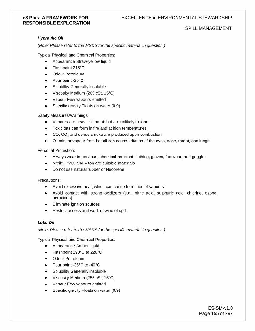
e3 Plus: A FRAMEWORK FOR EXCELLENCE in ENVIRONMENTAL STEWARDSHIP RESPONSIBLE EXPLORATION
SPILL MANAGEMENT
ES-SM-v1.0 Page 155 of 297
Hydraulic Oil
(Note: Please refer to the MSDS for the specific material in question.) Typical Physical and Chemical Properties:
Appearance Straw-yellow liquid
Flashpoint 215°C
Odour Petroleum
Pour point -25°C
Solubility Generally insoluble
Viscosity Medium (265 cSt, 15°C)
Vapour Few vapours emitted
Specific gravity Floats on water (0.9) Safety Measures/Warnings:
Vapours are heavier than air but are unlikely to form
Toxic gas can form in fire and at high temperatures
CO, CO2 and dense smoke are produced upon combustion
Oil mist or vapour from hot oil can cause irritation of the eyes, nose, throat, and lungs Personal Protection:
Always wear impervious, chemical-resistant clothing, gloves, footwear, and goggles
Nitrile, PVC, and Viton are suitable materials
Do not use natural rubber or Neoprene
Precautions:
Avoid excessive heat, which can cause formation of vapours
Avoid contact with strong oxidizers (e.g., nitric acid, sulphuric acid, chlorine, ozone, peroxides)
Eliminate ignition sources
Restrict access and work upwind of spill
Lube Oil
(Note: Please refer to the MSDS for the specific material in question.) Typical Physical and Chemical Properties:
Appearance Amber liquid
Flashpoint 190°C to 220°C
Odour Petroleum
Pour point -35°C to -40°C
Solubility Generally insoluble
Viscosity Medium (255 cSt, 15°C)
Vapour Few vapours emitted
Specific gravity Floats on water (0.9)

e3 Plus: A FRAMEWORK FOR EXCELLENCE in ENVIRONMENTAL STEWARDSHIP RESPONSIBLE EXPLORATION
SPILL MANAGEMENT
ES-SM-v1.0 Page 156 of 297
Safety Measures/Warnings:
Vapours are heavier than air but are unlikely to form
Toxic gas can form in fire and at high temperatures
CO, CO2 and dense smoke are produced upon combustion
Oil mist or vapour from hot oil can cause irritation of the eyes, nose, throat, and lungs Personal Protection:
Always wear impervious, chemical-resistant clothing, gloves, footwear, and goggles
Nitrile, PVC, and Viton are suitable materials
Do not use natural rubber or Neoprene Precautions:
Avoid excessive heat, which can cause formation of vapours
Avoid contact with strong oxidizers (e.g., nitric acid, sulphuric acid, chlorine, ozone, peroxides)
Eliminate ignition sources
Restrict access and work upwind of spill
Waste Oil
(Note: Please refer to the MSDS for the specific material in question.)
Typical Physical and Chemical Properties:
Appearance Black to brown liquid
Flashpoint 100°C to 200°C
Odour Petroleum
Pour point -30°C to 40°C
Solubility Generally insoluble
Viscosity Medium (200 to 300 cSt)
Vapour Few vapours emitted
Specific gravity Floats on water (0.9) Safety Measures/Warnings:
Vapours are heavier than air but are unlikely to form
Toxic gas can form in fire and at high temperatures
CO, CO2 and dense smoke are produced upon combustion
Personal Protection:
Always wear impervious, chemical-resistant clothing, gloves, footwear, and goggles
Nitrile, PVC, and Viton are suitable materials
Do not use natural rubber or neoprene
Use of organic vapour cartridge respirator is highly unlikely Precautions:
Avoid excessive heat, which can cause formation of vapours
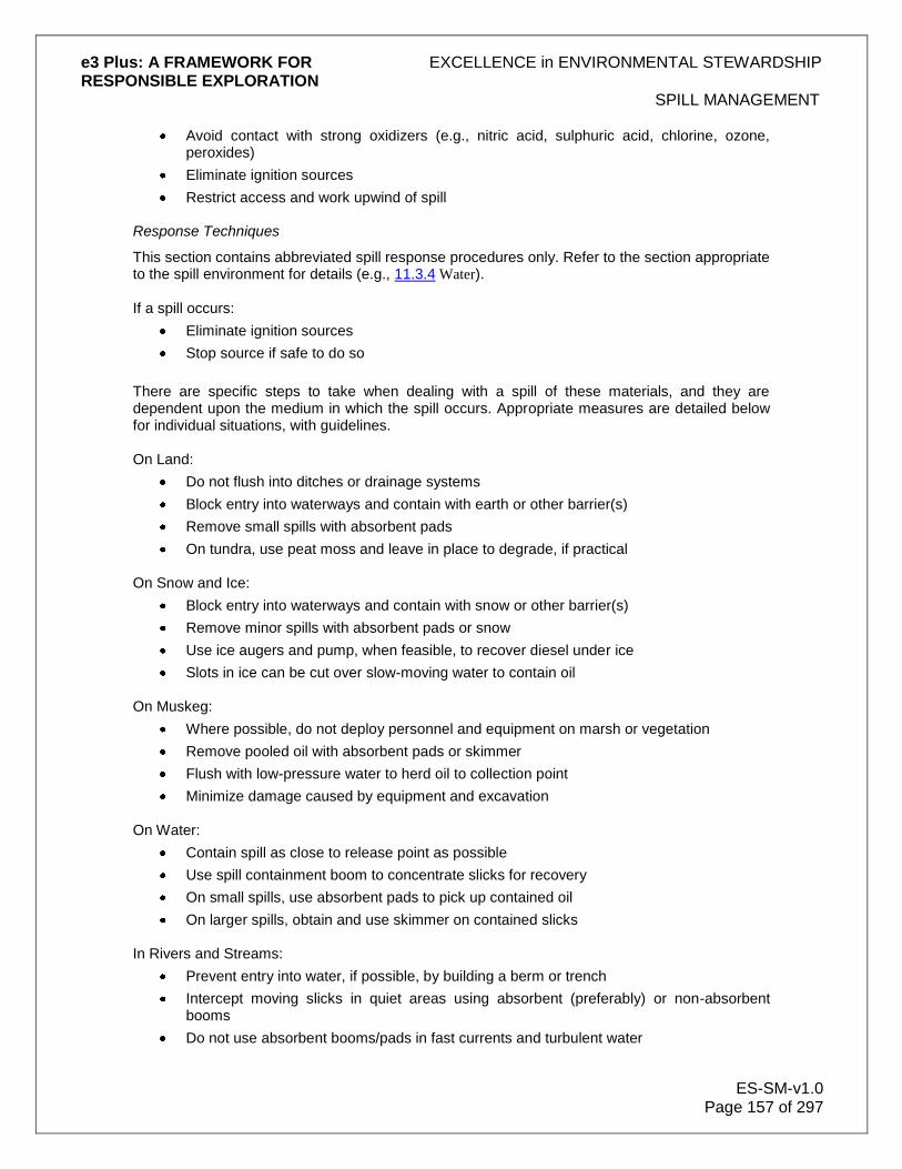
e3 Plus: A FRAMEWORK FOR EXCELLENCE in ENVIRONMENTAL STEWARDSHIP RESPONSIBLE EXPLORATION
SPILL MANAGEMENT
ES-SM-v1.0 Page 157 of 297
Avoid contact with strong oxidizers (e.g., nitric acid, sulphuric acid, chlorine, ozone, peroxides)
Eliminate ignition sources
Restrict access and work upwind of spill Response Techniques
This section contains abbreviated spill response procedures only. Refer to the section appropriate to the spill environment for details (e.g., 11.3.4 Water). If a spill occurs:
Eliminate ignition sources
Stop source if safe to do so
There are specific steps to take when dealing with a spill of these materials, and they are dependent upon the medium in which the spill occurs. Appropriate measures are detailed below for individual situations, with guidelines. On Land:
Do not flush into ditches or drainage systems
Block entry into waterways and contain with earth or other barrier(s)
Remove small spills with absorbent pads
On tundra, use peat moss and leave in place to degrade, if practical On Snow and Ice:
Block entry into waterways and contain with snow or other barrier(s)
Remove minor spills with absorbent pads or snow
Use ice augers and pump, when feasible, to recover diesel under ice
Slots in ice can be cut over slow-moving water to contain oil On Muskeg:
Where possible, do not deploy personnel and equipment on marsh or vegetation
Remove pooled oil with absorbent pads or skimmer
Flush with low-pressure water to herd oil to collection point
Minimize damage caused by equipment and excavation On Water:
Contain spill as close to release point as possible
Use spill containment boom to concentrate slicks for recovery
On small spills, use absorbent pads to pick up contained oil
On larger spills, obtain and use skimmer on contained slicks In Rivers and Streams:
Prevent entry into water, if possible, by building a berm or trench
Intercept moving slicks in quiet areas using absorbent (preferably) or non-absorbent booms
Do not use absorbent booms/pads in fast currents and turbulent water

e3 Plus: A FRAMEWORK FOR EXCELLENCE in ENVIRONMENTAL STEWARDSHIP RESPONSIBLE EXPLORATION
SPILL MANAGEMENT
ES-SM-v1.0 Page 158 of 297
Storage and Transfer:
Store closed, labelled containers outside, away from flammable items
Electrically ground containers and vehicles during transfer to designated disposal/treatment area
Disposal:
Segregate waste types
Place contaminated materials into marked containers
11.3.1.2 Gasoline and Jet B Aviation Fuel
This section contains information on physical properties, safety, and response techniques for Gasoline and Jet B Aviation fuel. This information will help to deal effectively with a spill of either of these in an exploration program. Each is dealt with separately in the subsections below. Physical Properties and Safety
Always remember that both Gasoline and Jet B form vapours that can ignite and explode. Never smoke in their vicinity. Also ensure that all containers are properly grounded while being filled. Gasoline
(Note: Please refer to the MSDS for the specific material in question.) Typical Physical and Chemical Properties:
Appearance Colourless liquid (can be dyed)
Flashpoint -50°C
Odour Gasoline/Petroleum
Freezing point -60°C
Solubility Insoluble
Viscosity Not viscous (<1 cSt)
Vapour Will sink to ground levels
Specific gravity Floats on water (0.7 to 0.8) Safety Measures/Warnings:
Vapours form instantaneously and are heavier than air
Empty containers can contain explosive vapours
Vapours can travel to distant sources of ignition and flash back
Eye contact causes irritation
Material can accumulate static charges
Inhalation of vapours can cause irritation of the respiratory tract, headache, vomiting, and unconsciousness
Personal Protection:
Always wear impervious, chemical-resistant clothing, gloves, footwear, and goggles
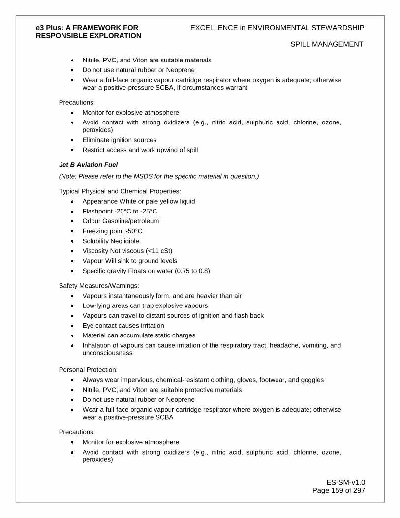
e3 Plus: A FRAMEWORK FOR EXCELLENCE in ENVIRONMENTAL STEWARDSHIP RESPONSIBLE EXPLORATION
SPILL MANAGEMENT
ES-SM-v1.0 Page 159 of 297
Nitrile, PVC, and Viton are suitable materials
Do not use natural rubber or Neoprene
Wear a full-face organic vapour cartridge respirator where oxygen is adequate; otherwise wear a positive-pressure SCBA, if circumstances warrant
Precautions:
Monitor for explosive atmosphere
Avoid contact with strong oxidizers (e.g., nitric acid, sulphuric acid, chlorine, ozone, peroxides)
Eliminate ignition sources
Restrict access and work upwind of spill
Jet B Aviation Fuel
(Note: Please refer to the MSDS for the specific material in question.) Typical Physical and Chemical Properties:
Appearance White or pale yellow liquid
Flashpoint -20°C to -25°C
Odour Gasoline/petroleum
Freezing point -50°C
Solubility Negligible
Viscosity Not viscous (<11 cSt)
Vapour Will sink to ground levels
Specific gravity Floats on water (0.75 to 0.8) Safety Measures/Warnings:
Vapours instantaneously form, and are heavier than air
Low-lying areas can trap explosive vapours
Vapours can travel to distant sources of ignition and flash back
Eye contact causes irritation
Material can accumulate static charges
Inhalation of vapours can cause irritation of the respiratory tract, headache, vomiting, and unconsciousness
Personal Protection:
Always wear impervious, chemical-resistant clothing, gloves, footwear, and goggles
Nitrile, PVC, and Viton are suitable protective materials
Do not use natural rubber or Neoprene
Wear a full-face organic vapour cartridge respirator where oxygen is adequate; otherwise wear a positive-pressure SCBA
Precautions:
Monitor for explosive atmosphere
Avoid contact with strong oxidizers (e.g., nitric acid, sulphuric acid, chlorine, ozone, peroxides)
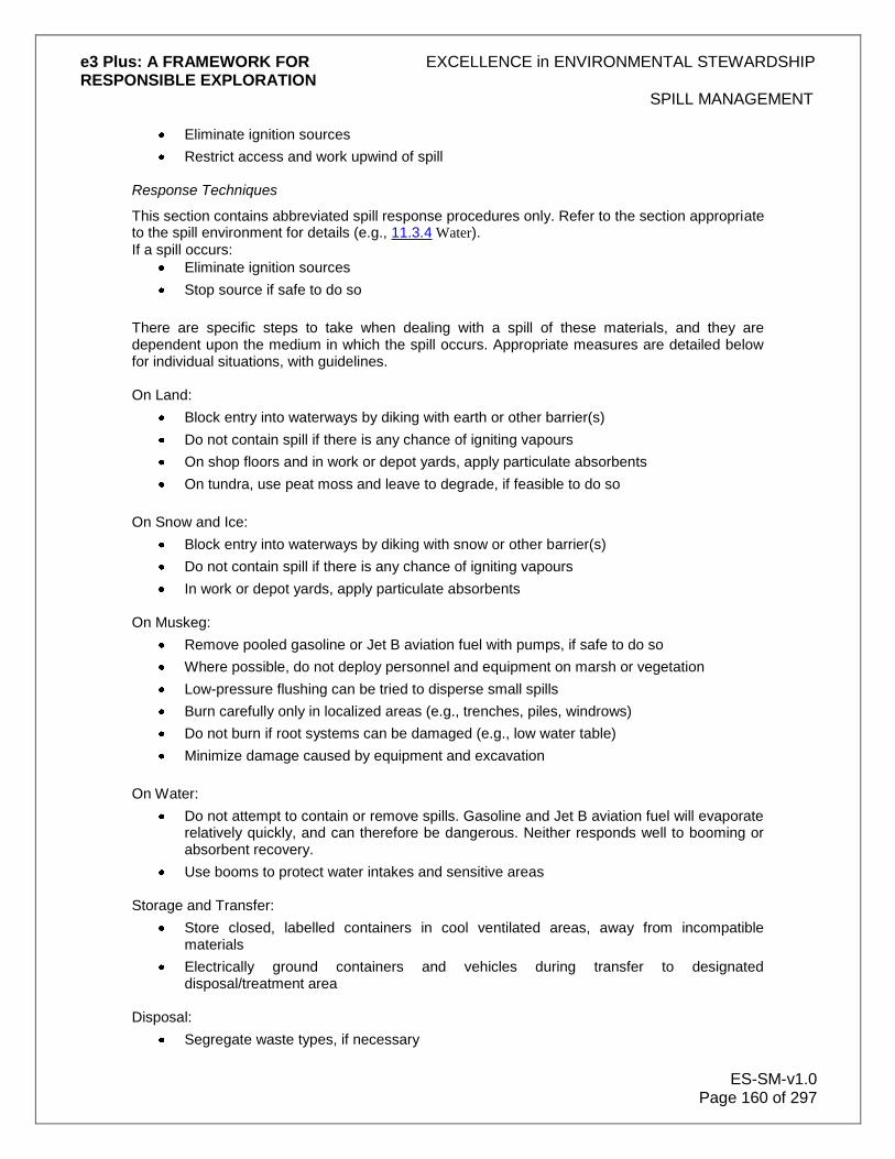
e3 Plus: A FRAMEWORK FOR EXCELLENCE in ENVIRONMENTAL STEWARDSHIP RESPONSIBLE EXPLORATION
SPILL MANAGEMENT
ES-SM-v1.0 Page 160 of 297
Eliminate ignition sources
Restrict access and work upwind of spill Response Techniques
This section contains abbreviated spill response procedures only. Refer to the section appropriate to the spill environment for details (e.g., 11.3.4 Water).
If a spill occurs:
Eliminate ignition sources
Stop source if safe to do so
There are specific steps to take when dealing with a spill of these materials, and they are dependent upon the medium in which the spill occurs. Appropriate measures are detailed below for individual situations, with guidelines. On Land:
Block entry into waterways by diking with earth or other barrier(s)
Do not contain spill if there is any chance of igniting vapours
On shop floors and in work or depot yards, apply particulate absorbents
On tundra, use peat moss and leave to degrade, if feasible to do so
On Snow and Ice:
Block entry into waterways by diking with snow or other barrier(s)
Do not contain spill if there is any chance of igniting vapours
In work or depot yards, apply particulate absorbents On Muskeg:
Remove pooled gasoline or Jet B aviation fuel with pumps, if safe to do so
Where possible, do not deploy personnel and equipment on marsh or vegetation
Low-pressure flushing can be tried to disperse small spills
Burn carefully only in localized areas (e.g., trenches, piles, windrows)
Do not burn if root systems can be damaged (e.g., low water table)
Minimize damage caused by equipment and excavation
On Water:
Do not attempt to contain or remove spills. Gasoline and Jet B aviation fuel will evaporate relatively quickly, and can therefore be dangerous. Neither responds well to booming or absorbent recovery.
Use booms to protect water intakes and sensitive areas Storage and Transfer:
Store closed, labelled containers in cool ventilated areas, away from incompatible materials
Electrically ground containers and vehicles during transfer to designated disposal/treatment area
Disposal:
Segregate waste types, if necessary

e3 Plus: A FRAMEWORK FOR EXCELLENCE in ENVIRONMENTAL STEWARDSHIP RESPONSIBLE EXPLORATION
SPILL MANAGEMENT
ES-SM-v1.0 Page 161 of 297
Place contaminated materials into marked containers
11.3.1.3 Other Hazardous Materials
This section contains information on physical properties, safety and response techniques for antifreeze, propane, acetylene and raw sewage, all of which may be considered hazardous materials. This information will help to deal effectively with a spill of any of these in an exploration program. Each is dealt with separately in the subsections below. Ethylene Glycol Antifreeze
(Note: Please refer to the MSDS for the specific material in question.) Typical Physical and Chemical Properties:
Appearance Colourless liquid
Flashpoint 111°C
Odour Slight; undetectable; <25 ppm
Pour point -13°C
Solubility Soluble in all proportions
Viscosity Not viscous (~22 cSt)
Vapour Will sink to ground levels
Specific gravity Same as water (1.0) Safety Measures/Warnings:
Vapours are heavier than air.
Ingestion of significant quantities can be lethal.
Eye contact causes irritation.
Skin contact can cause intoxication due to absorption.
Inhalation of vapours can cause intoxication, headache, vomiting, unconsciousness with convulsions, and even death. Avoid inhaling vapours, particularly in enclosed places.
Personal Protection:
Always wear impervious, chemical-resistant clothing, gloves, footwear, and goggles
Neoprene, Nitrile, and PVC are suitable protective materials Precautions:
Monitor empty containers for explosive atmosphere
Avoid contact with strong oxidizers (e.g., nitric acid, sulphuric acid, chlorine, ozone, peroxides)
Propane
(Note: Please refer to the MSDS for the specific material in question.) Typical Physical and Chemical Properties:
Appearance Colourless gas

e3 Plus: A FRAMEWORK FOR EXCELLENCE in ENVIRONMENTAL STEWARDSHIP RESPONSIBLE EXPLORATION
SPILL MANAGEMENT
ES-SM-v1.0 Page 162 of 297
Flashpoint -104°C
Odour Natural gas odour
Freezing point -190°C
Solubility Insoluble
Viscosity n/a
Vapour Will sink to ground levels
Specific gravity Liquid floats on water (0.6) Safety Measures/Warnings:
Vapours form instantaneously and are heavier than air
Vapours can travel to distant sources of ignition and flash back
Eye contact causes irritation
Material can accumulate static charges and unconsciousness Personal Protection:
Always wear impervious, chemical-resistant clothing, gloves, footwear, and goggles
Nitrile and Viton are suitable protective materials
Do not use natural PVC and rubber or Neoprene
Avoid frostbite burn to skin and eyes from contact with propane
Wear a full-face organic vapour cartridge respirator where oxygen is adequate; otherwise wear a positive-pressure SCBA
Precautions:
Monitor for explosive atmosphere
Avoid contact with strong oxidizers (e.g., nitric acid, sulphuric acid, chlorine, ozone, peroxides)
Eliminate ignition sources
Restrict access and work upwind of spill
Acetylene
(Note: Please refer to the MSDS for the specific material in question.)
Typical Physical and Chemical Properties:
Appearance Colourless gas
Flashpoint -18°C
Odour Garlic-like
Freezing point -82°C
Solubility Slightly soluble
Viscosity N/a
Vapour Will sink to ground levels
Specific gravity Liquid floats on water (0.6) Safety Measures/Warnings:
Vapours form instantaneously and are heavier than air
Empty containers can contain explosive vapours

e3 Plus: A FRAMEWORK FOR EXCELLENCE in ENVIRONMENTAL STEWARDSHIP RESPONSIBLE EXPLORATION
SPILL MANAGEMENT
ES-SM-v1.0 Page 163 of 297
Vapours can travel to distant sources of ignition and flash back
Eye contact causes irritation
Material can accumulate static charges
Inhalation of vapours can cause irritation of the respiratory tract, headache, vomiting, and unconsciousness
Personal Protection:
Always wear impervious, chemical-resistant clothing, gloves, footwear, and goggles
Nitrile and Viton are suitable protective materials
Do not use natural PVC and rubber or Neoprene
Wear a full-face organic vapour cartridge respirator where oxygen is adequate; otherwise wear a positive-pressure SCBA
Precautions:
Monitor for explosive atmosphere
Avoid contact with strong oxidizers (e.g., nitric acid, sulphuric acid, chlorine, ozone, peroxides)
Eliminate ignition sources
Restrict access and work upwind of spill
Gases stored in cylinders can explode when ignited
Keep vehicles away from accident area
Raw Sewage Typical Physical and Chemical Properties:
Appearance Brown to black liquid
Flashpoint n/a
Odour Pungent, foul
Pour point 0°C to 10°C
Solubility Partly soluble
Viscosity variable
Vapour n/a
Specific gravity 1.2 to 1.5 Safety Measures/Warnings:
Inhalation of fumes can cause nausea
Ingestion may be harmful
Eye contact causes irritation
Repeated skin contact can cause irritation Personal Protection:
Always wear impervious, chemical-resistant clothing, gloves, footwear, and goggles Precautions:
Prevent from contacting water
Keep personnel away from spill area

e3 Plus: A FRAMEWORK FOR EXCELLENCE in ENVIRONMENTAL STEWARDSHIP RESPONSIBLE EXPLORATION
SPILL MANAGEMENT
ES-SM-v1.0 Page 164 of 297
Demarcate area and keep vehicles and equipment away
Response Techniques
This section contains abbreviated spill response procedures only. Refer to the section appropriate to the spill environment for details (e.g., 11.3.4 Water). There are specific steps to take when dealing with a spill of each of these materials, and they are also dependent upon the medium in which the spill occurs. Appropriate measures are detailed below for individual situations, with guidelines. Ethylene Glycol Antifreeze
Eliminate ignition sources
Restrict access and work upwind of spill On Land:
Block entry into waterways
Do not flush into ditches or drainage systems
Contain spill by diking with earth or other barrier(s)
Remove minor spills with universal absorbent
Remove large spills with pumps or vacuum equipment On Snow and Ice:
Block entry into waterways
Do not flush into ditches or drainage systems
Contain spill by diking with snow or other barrier(s)
Remove minor spills with universal absorbent
Remove contaminated snow with shovels and mechanical equipment On Muskeg:
Remove pooled antifreeze with pumps
Where possible, do not deploy personnel and equipment on marsh or vegetation
Burning is not feasible
Minimize damage caused by equipment and excavation On Water:
Ethylene glycol sinks and mixes with water
Isolate and/or confine spill by damming or diversion Storage and Transfer:
Store closed, labelled containers in cool, ventilated areas
Store away from incompatible materials (e.g., organics, finely divided metals, oxidizable materials)
Disposal:
Segregate waste types
Place contaminated materials into marked containers
Propane and Acetylene

e3 Plus: A FRAMEWORK FOR EXCELLENCE in ENVIRONMENTAL STEWARDSHIP RESPONSIBLE EXPLORATION
SPILL MANAGEMENT
ES-SM-v1.0 Page 165 of 297
Vapours cannot be contained when released
Water spray can be used to knock down vapours only if there is no chance of ignition
Small fires can be extinguished with dry chemical or CO2
Unless a small leak is stopped upon first detection, personnel should withdraw immediately from area
If tanks are damaged, gas should be allowed to disperse and no attempt at recovery should be made
Avoid touching release point on containers, as frost quickly forms
Keep away from tank ends
Raw Sewage On Land:
Block entry into waterways
Do not flush into ditches or drainage systems
Contain spill by diking with earth or other barrier(s)
Remove spills with pumps or vacuum equipment
On tundra, use peat moss and leave in place to degrade, if feasible On Snow and Ice:
Block entry into waterways
Do not flush into ditches or drainage systems
Contain spill by diking with snow or other barrier(s)
Remove contaminated snow with shovels or mechanical equipment On Muskeg:
Where possible, do not deploy personnel and equipment on marsh or vegetation
Remove pooled sewage with pumps or vacuum equipment
Leave in place if more damage will result from cleanup
Minimize damage caused by equipment and personnel On Water:
Sewage sinks and mixes with water
Isolate and/or confine spill by damming or diversion
If not possible to confine and pump, disperse using water flushing Storage and Transfer:
Store closed, labelled containers in cool, ventilated areas
Avoid contact with collected material Disposal:
Consider using as a fertilizer in designated areas
Place into marked containers
Transport to the designated sewage treatment plant

e3 Plus: A FRAMEWORK FOR EXCELLENCE in ENVIRONMENTAL STEWARDSHIP RESPONSIBLE EXPLORATION
SPILL MANAGEMENT
ES-SM-v1.0 Page 166 of 297
11.3.2 Land
In the case of a spill, move rapidly to respond to the accident. Quick containment of oil on land is necessary to ensure that spilled oil does not spread over a large surface area, thus increasing the potential for greater surface coverage and subsurface contamination. This is particularly so when spills occur in loosely packed materials (e.g., sand, soil, pebbles, cobbles, boulders). Always remember that the potential for penetration and spreading increases with light products, such as:
Diesel
Jet B aviation fuel
Gasoline All oil-based products are heavier than air and will flow, either as a liquid or gas, to low points downhill and away from the initial spill source. The first priority must always be for the protection and preservation of life. One of the main considerations to keep in mind when assessing a spill is the type of material that has been spilled. If it is a volatile product (e.g., gasoline) that has been spilled, the potential for fire and explosion from a nearby source of ignition must be immediately considered. Key actions that are necessary in response to the spill of a volatile produce include:
Removal of ignition sources
Notification and evacuation of personnel at risk
Completion of an observation-based assessment, to determine if it is safe to commence any spill counter-measure operations; if unsafe, do not commence these measures
In most cases, a simple trench can be dug ahead of the spill, on the downhill side. Spilled oil will then flow into the trench and can be removed with absorbent booms, pads, buckets, or pumps. To facilitate this:
Construct a soil berm downslope of the spill
If appropriate, use synthetic, impervious sheeting to act as a barrier
Where possible, recover spills through manual or mechanical means, including shovels, heavy equipment, and pumps
Absorb petroleum residue with synthetic absorbent pad materials
Recover spilled and contaminated material, including soil and vegetation Once removed, contaminated oil or soil can be placed into drums or containers for later disposal. Never flush oil-based products into ditches or drainage systems. Block entry into waterways and contain the spill with earth or other barrier(s). Small Spills
Small spills can be cleaned up with absorbent pads. On tundra, peat moss can be spread and left in place to degrade, if practical. In situations in remote areas, where small spills of hydrocarbons have soaked into soil on level ground, it may be best to attempt biological remediation. To break down the hydrocarbons using bacteria, turn over the contaminated soil by shovel, and mix fertilizer and straw into the soil. Test the soil annually to determine hydrocarbon levels.
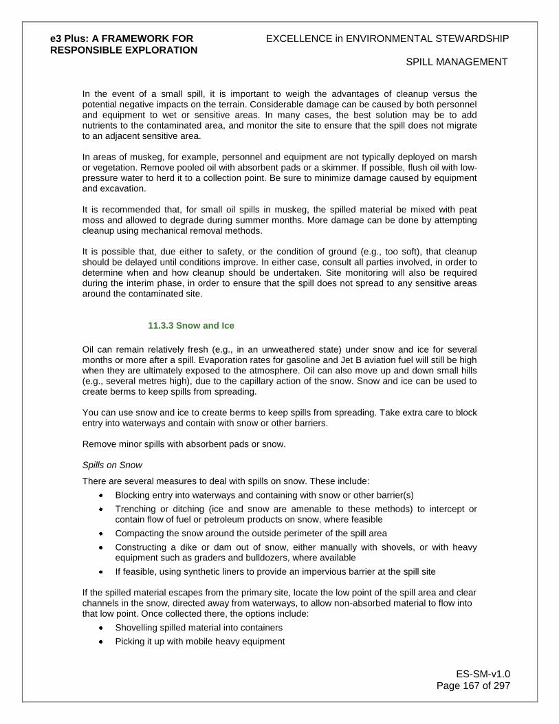
e3 Plus: A FRAMEWORK FOR EXCELLENCE in ENVIRONMENTAL STEWARDSHIP RESPONSIBLE EXPLORATION
SPILL MANAGEMENT
ES-SM-v1.0 Page 167 of 297
In the event of a small spill, it is important to weigh the advantages of cleanup versus the potential negative impacts on the terrain. Considerable damage can be caused by both personnel and equipment to wet or sensitive areas. In many cases, the best solution may be to add nutrients to the contaminated area, and monitor the site to ensure that the spill does not migrate to an adjacent sensitive area. In areas of muskeg, for example, personnel and equipment are not typically deployed on marsh or vegetation. Remove pooled oil with absorbent pads or a skimmer. If possible, flush oil with low-pressure water to herd it to a collection point. Be sure to minimize damage caused by equipment and excavation. It is recommended that, for small oil spills in muskeg, the spilled material be mixed with peat moss and allowed to degrade during summer months. More damage can be done by attempting cleanup using mechanical removal methods. It is possible that, due either to safety, or the condition of ground (e.g., too soft), that cleanup should be delayed until conditions improve. In either case, consult all parties involved, in order to determine when and how cleanup should be undertaken. Site monitoring will also be required during the interim phase, in order to ensure that the spill does not spread to any sensitive areas around the contaminated site.
11.3.3 Snow and Ice
Oil can remain relatively fresh (e.g., in an unweathered state) under snow and ice for several months or more after a spill. Evaporation rates for gasoline and Jet B aviation fuel will still be high when they are ultimately exposed to the atmosphere. Oil can also move up and down small hills (e.g., several metres high), due to the capillary action of the snow. Snow and ice can be used to create berms to keep spills from spreading. You can use snow and ice to create berms to keep spills from spreading. Take extra care to block entry into waterways and contain with snow or other barriers. Remove minor spills with absorbent pads or snow. Spills on Snow
There are several measures to deal with spills on snow. These include:
Blocking entry into waterways and containing with snow or other barrier(s)
Trenching or ditching (ice and snow are amenable to these methods) to intercept or contain flow of fuel or petroleum products on snow, where feasible
Compacting the snow around the outside perimeter of the spill area
Constructing a dike or dam out of snow, either manually with shovels, or with heavy equipment such as graders and bulldozers, where available
If feasible, using synthetic liners to provide an impervious barrier at the spill site If the spilled material escapes from the primary site, locate the low point of the spill area and clear channels in the snow, directed away from waterways, to allow non-absorbed material to flow into that low point. Once collected there, the options include:
Shovelling spilled material into containers
Picking it up with mobile heavy equipment

e3 Plus: A FRAMEWORK FOR EXCELLENCE in ENVIRONMENTAL STEWARDSHIP RESPONSIBLE EXPLORATION
SPILL MANAGEMENT
ES-SM-v1.0 Page 168 of 297
Pumping liquids into tanker trucks
Using a vacuum truck to pick up material Pick up and transport liquid oil wastes or oil-contaminated snow at a land disposal site approved by government authorities and fire or safety consultants. The equipment to use will depend on the magnitude and location of the spill. Spills on Ice
Where spills have occurred on ice:
If feasible, contain material spilled using methods described above for snow, or attempt mechanical recovery with heavy equipment
Prevent fuel or petroleum products from penetrating ice and entering water sources
Remove contaminated material, including snow and/or ice as soon as possible Containment of fuel or petroleum products under an ice surface is difficult given the ice thickness and winter conditions. If spill materials get under ice:
Determine the area where the fuel or petroleum product is located
Drill holes through ice using an ice auger to locate the fuel or petroleum product.
Once detected, use chain saws to cut slots in the ice, and remove ice blocks (in frozen rivers, where safety permits, cut angled slots or holes about 1 m wide in the ice, to allow possible spill recovery)
The oil will rise up into the openings where it will concentrate, and be available for recovery using skimmers or pumps
Fuel or petroleum products collected in ice slots or holes can be picked up via suction hoses connected to a portable pump, vacuum truck, or standby tanker. Take care to prevent the end of the suction hose clogging up with snow, ice or debris.
11.3.4 Water
Attempt to contain spills as close to the release point as possible. Use spill containment booms to concentrate slicks for recovery. However, gasoline and Jet B aviation fuels do not respond well to booming and, because of their high evaporation rates, can be dangerous to deal with. On small spills, absorbent pads can be used to pick up contained oil. On larger spills with contained slicks, use a skimmer. If a full tanker truck breaks through ice into the water below, it will remain buoyant, since the densities of fuel and petroleum products are less than water. If this occurs, the first priority is to recover the driver of the truck safely. Buoyancy of the truck will be maintained while pumping at least a portion of its contained fuel from the truck to another vessel, until the truck can be retrieved safely. Make every effort to pull out the truck as soon as possible. Where sumps are used to contain drilling fluids, place an absorbent pad in the sump. The pad will float on the surface of the sump and soak up any fuel that makes its way into the sump during routine drilling operations. Further information on the use of sumps in drilling to contain return water is given the 10.0 Hazardous Material section of this e-toolkit. In the case of larger spills, booms should be deployed in the sump as described below. When spills occur near rivers and streams, attempt to prevent entry into water by building a berm or

e3 Plus: A FRAMEWORK FOR EXCELLENCE in ENVIRONMENTAL STEWARDSHIP RESPONSIBLE EXPLORATION
SPILL MANAGEMENT
ES-SM-v1.0 Page 169 of 297
trench. If oil enters a stream or river, moving slicks should be intercepted in calm areas, using absorbent booms. Do not use absorbent booms or pads in fast currents and turbulent water. Use of Booms
The following strategies can be used to contain spills on slow moving or calm water:
Contain spills on open water immediately to restrict the size and extent of the spill. Fuel and petroleum products that float on water may be contained through the use of booms, absorbent materials, skimming, or the erection of culverts.
Deploy containment booms to minimize spill area; the effectiveness of booms may be limited by wind, waves, and other factors.
Use absorbent booms to slowly encircle and absorb spilled material. These absorbents are hydrophobic (they absorb hydrocarbons and repel water).
Once booms are secured, use skimmers to draw in hydrocarbons and minimal amounts of water. Skimmed material can be pumped through hoses to empty fuel tanks and/or drums.
Recognize that culverts permit water flow and can allow fuel to be captured and collected along the surface with absorbent materials.
Use absorbent pads and similar materials to capture small spills and/or oily residue on water.
Determining the best possible strategy for containment will depend on a number of factors, such as:
Speed of slick travel
Location of possible containment sites
Availability of personnel and equipment
Location of sensitive areas
Safety of operations Booming with either absorbent or non-absorbent booms is an effective means of containing spills on slow-moving waters and in lakes. Effective containment using conventional booming techniques is very difficult in streams or rivers where currents exceed 0.7 knots (0.4 m/s). At these speeds, oil becomes entrained in the water flowing under the boom, resulting in significant losses. Some improvement can be achieved in waters flowing at 1-2 knots (0.5 m/s to 1 m/s), if the boom is deployed at an angle of less than 90° to the direction of flow. Absorbent booms or socks can also be used to provide a barrier to floating oil. These types of booms should be checked regularly, to ensure that they do not become saturated with either water or oil, as they tend to float very low in the water or even sink and release oil downstream. Marine Spills
A marine oil spill could occur at any point along a fuel transfer system between a tanker and onshore storage tanks. The general strategy for near-shore marine spill responses is to limit the spread of oil on water, through downwind or down-current booming and collection at an accessible shoreline location. Oil stranded on a beach can be manually removed or refloated at high water. When dealing with refloated oil, set a boom downwind for collection. Any oil can be herded on the water's surface by using water hoses with nozzles having a diffused spray setting. If there is oil stranded on the mid-to-lower levels of tidal flats, it may be possible to collect it in the natural tidal pools formed in the sand. Collection in such pools can be accelerated by low-pressure deluge washing of the higher sections of the flats, and the manual digging of drainage ditches leading to the collection points.

e3 Plus: A FRAMEWORK FOR EXCELLENCE in ENVIRONMENTAL STEWARDSHIP RESPONSIBLE EXPLORATION
SPILL MANAGEMENT
ES-SM-v1.0 Page 170 of 297
Oil on seawater can be recovered using skimmers. For maximum encounter rates, place skimmers at the apex of a collection boom. Skimmers may also be used in larger tidal pools. Pump liquid oil and oily water into suitable containers, such as 205 L drums or larger dedicated tanks. Use absorbent pads to collect oil in shallow pools and fresh oil stranded on beaches. Absorbents must be bagged for disposal. Oil mixed with sand must be collected and bagged for disposal. Due to the instability of sand beaches, and the resultant difficulty in operating heavy equipment, oily sand removal may be limited to manual shovel activities.
11.3.5 Alternative Techniques
In-situ combustion (burning) is a disposal method that may be available for fuels and petroleum products. Prior to any attempts at in-situ burning, however, experts must be consulted and approval obtained from government authorities. Burning of fuels and petroleum products is very dangerous; unauthorized burning should never be attempted. In-situ burning technique is discussed separately in more detail below. Chemical response methods are also available, and may include the use of the following:
Dispersants
Emulsion-treating agents
Visco-elastic agents
Herding agents
Solidifiers
Shoreline cleaning agents Biological response methods include nutrient enrichment and natural microbe seeding. Burning
The in-situ burning of spilled oil may be a useful option, particularly in arctic conditions, where terrain or safety concerns may make conventional cleanup methods impractical. It is critically important that the decision to burn be made as soon as possible after the spill because, as the more volatile light ends evaporate, burning becomes more difficult. For this reason, it is recommended to obtain prior approval (that is, before the program is commenced) from the necessary regulatory agencies. Application
In-situ burning can be initiated by using a large-size portable propane torch (e.g., Tiger Torch) to ignite the fuel/petroleum products. Highly flammable products (e.g., gasoline or alcohol), or combustible material (e.g., wood), may be used to promote ignition of the spilled product. The objective is to raise the temperature for sustained combustion of the spilled product. In winter, or in muskeg with a high water table, the best results will be achieved when burning spills that are fresh (less than 24 hours old). Burning can also be effective in containment trenches or ponds, where a significant oil thickness can collect. Special care should be taken in winter conditions, as the heat from the burn will melt adjacent snow, increasing the potential for penetration of the oil, and potentially transporting the oil to the surrounding area. Care must also be exercised during the summer in fragile arctic or alpine terrain. Naturally occurring bog and other plants on the tundra can burn, creating more damage than the original spill. Material for burning should be isolated from the surrounding terrain (in

e3 Plus: A FRAMEWORK FOR EXCELLENCE in ENVIRONMENTAL STEWARDSHIP RESPONSIBLE EXPLORATION
SPILL MANAGEMENT
ES-SM-v1.0 Page 171 of 297
windrows or containers) prior to burning, if there is any chance whatever of adjacent areas being inadvertently set on fire. In-situ burning may be used in the disposal of fuel or petroleum products that have collected in ice slots, if sufficient holes are drilled in the ice. Once all the holes are drilled, the oil that collects in the holes can be ignited. Before doing so, however, fire/safety consultants must be consulted and approval obtained from government authorities. Limitations
Heavy or weathered oil is very difficult or even impossible to burn. Severe weather conditions such as high winds, snow and rain may also make burning impossible. Do not burn in areas with vegetation cover that has not been severely damaged by the oil, as more damage will result than if the oil is left to degrade naturally. Burning should be considered only in localized areas, where the spilled material has pooled naturally or been contained via dikes, trenches, windrows, depressions, or ice slots. Take care in muskeg with a relatively low water table, as burning may destroy sensitive root systems. Oil residues left after controlled, in-situ burning must be picked up and disposed of at a land disposal site approved by government authorities and fire and safety consultants. Safety
As with conventional cleanup methods, safety of operations is paramount in burning operations. Only carry out burning in contained areas or where firebreaks are employed. Muskeg and tundra can smoulder for a considerable time after a burn, and care should be taken to ensure that it does not ignite later, either from underground (root) systems or surface materials. Personnel involved in the burn should be fully trained in safe burning procedures, including methods for avoiding the inhalation of potentially dangerous smoke or vapours.
11.4 Site Restoration
Site restoration, stream banks and general "shoreline" cleanup of lakes are the final spill response steps. Due to seasonal variations and various types of stream banks and muskeg, a standard restoration program cannot be prescribed. Early consultation with environmental advisors is critical to ensuring cleanup efforts do not create adverse impacts. As a general rule, cleanup should minimize the impact to shoreline or muskeg, particularly vegetated areas, during all phases of spill response. Cleanup can cause more damage than an untreated spill in such habitats, especially where permafrost and vegetation are involved. Assess the area requiring cleanup in terms of 3 factors:
Environmental sensitivity
Property, archaeological or other damage
Natural cleansing action at the site Oil typically does not adhere to the banks of fast-moving rivers. Usually, little or no cleanup action can be taken. On the other hand, muskeg can undergo long-term contamination and reduced environmental productivity that cleanup may or may not help to alleviate, because of other damage that may be inflicted. Whatever the method is chosen to deal with an area affected by a spill, it is vital to minimize damage to root systems.

e3 Plus: A FRAMEWORK FOR EXCELLENCE in ENVIRONMENTAL STEWARDSHIP RESPONSIBLE EXPLORATION
SPILL MANAGEMENT
ES-SM-v1.0 Page 172 of 297
In the cleanup process, always:
Obtain approval and instruction prior to conducting cleanup operations.
Be particularly careful if oil has entered marshy areas and wetlands. Do not deploy personnel and equipment into such areas without explicit approval from environmental authorities. Damage to both upland and water areas may result.
If cleanup is to be attempted in vegetated areas and other sensitive zones, approach from the waterside if possible. Be aware that various plant species, birds, fish, and animals can all be adversely affected by cleanup operations. In the Arctic, breeding and blooming periods during the summer months are particularly critical.
11.5 Reporting
Reporting of the spill, whether to management or to the appropriate authorities, is the responsibility of the designated Team Leader. Determine if the situation constitutes a crisis and, if so, follow the Crisis Management policy if there is one. When reporting an incident to regulatory authorities, provide the following information:
Name and telephone number
The time, location, and source of the spill
The type of spilled material
The owner of the spilled material, if known
The cause of the spill, if known Report spills or accidents that immediately threaten public safety (e.g., gasoline and chemical spills) directly to the local fire department or other appropriate authority. Timing of Reports for Spills
Use the highest priority and the quickest means available to make the initial report after a spill. Add particulars not immediately available in a supplementary message as soon as possible after the initial report. Transmit follow-up reports as needed at regular intervals, to keep those involved informed of developments. As a general guideline, in the case of a major spill, transmit the initial report within one-half hour of the incident, and send follow-up reports at least each hour thereafter.
11.6 Disposal
For appropriate disposal, refer to data describing the physical properties of the spilled material, and identify hazards and disposal requirements. This data will generally be found in the Material Safety Data Sheets (MSDS) or their equivalent. As a general rule, segregate waste materials as much as possible. During disposal, use the appropriate personal protective equipment (e.g., gloves, goggles, face shield, apron, boots), and exercise appropriate care to place spilled material into suitable, properly marked containers. Spilled materials must be disposed of at an approved site, and it is the company‟s responsibility to check with local authorities for the most appropriate location.

e3 Plus: A FRAMEWORK FOR EXCELLENCE in ENVIRONMENTAL STEWARDSHIP RESPONSIBLE EXPLORATION
SPILL MANAGEMENT
ES-SM-v1.0 Page 173 of 297
11.7 Spill Kits
Have spill kits available for use at any exploration operation in which fuels or other potentially hazardous materials are being used. The choice of spill kits should be suited to the environment and the size of exploration project. Guidelines for the contents of spill kits for land and water-based situations are given in the subsections that follow. Also ensure that fire protective equipment is readily available, and that personnel are properly trained in the use of fire extinguishers and hoses.
11.7.1 Spill Kits – Land
For land-based spills, consider the following as appropriate spill kits. The makeup of these will depend upon the size of the exploration operation. Standard Spill Kit:
A 205 L 16 gauge drum
2 closing rings - one for ease of entry into the drum, and the other to ensure absolute containment of hazardous products for transport and temporary storage
1 pair of Neoprene/oil/chemical-resistant gloves
1 protective disposable suit
1 pair of protective goggles
12 m of 12 cm containment boom
25 absorbent pads - approximately 46 cm x 46 cm x 8 mm thick
23 m of absorbent blanket - approximately 70 cm x 8 mm thick
2 polyethylene bags approximately – 71 cm x 46 cm x 165 cm to 3 mm thick
Shovel Spill Kit for Limited Fuel Storage (< 1,000 L) Areas:
1 pair of Neoprene/oil/chemical-resistant gloves
1 pair of protective goggles
10 absorbent pads - approximately 46 cm x 46 cm x 8 mm thick
1 polyethylene bag - approximately 71 cm x 46 cm x 165 cm to 3 mm thick
Shovel
11.7.2 Spill Kits – Water
As with the land spills, a water spill kit size will depend upon the amount of fuel and other petroleum products stored at the exploration site. Some guidelines for these are set out below. Spill Kits for Limited Fuel Storage (< 2,000 L) Areas:
1 rope (15 m minimum length)
1 container of Gap Seal drum sealant
6 absorbent "socks" (1 m length)
2 mini-booms

e3 Plus: A FRAMEWORK FOR EXCELLENCE in ENVIRONMENTAL STEWARDSHIP RESPONSIBLE EXPLORATION
SPILL MANAGEMENT
ES-SM-v1.0 Page 174 of 297
1 drum roll kit
1 bag of peat moss
5 hazardous waste bags
3 pairs chemical-resistant safety gloves
Spill Kits for Extensive Fuel Storage (> 2,000 L) Areas:
1 x 150 m flotation boom
6 x 15 kg grapnel anchors
3 Norwegian anchor buoys
8 standard marine buoys (yellow)
4 x 100 m coils anchor rope (1 cm)
5 x 200 m coils towline rope (1 cm)
1 x 6 m response boat with 80 HP outboard motor
2 lifejackets
20 bags peat moss
1 x 1.3 m absorbent roll
15 absorbent pads
2 fire extinguishers
1 drum skimmer
1 pump
Waste Storage:
3 x 175 L drum response kits with lids
Personal Equipment:
1 emergency eyewash station
20 pairs POL (Petroleum, Oil, Lubricants)-resistant gloves
7 pairs POL-resistant goggles
1 bag 20 disposable respirators
2 pairs safety hip waders
1 toolbox (assorted tools)
2 x 25 L containers with lids
100 m nylon rope (1 cm thick)
11.8 Documentation
Keep good written and photographic records of spill occurrences, and written records of spill response procedures. Spill documentation records include, but are not limited to:
Spill response plans
Inspections and audits of worksites and work activities
Lists and MSDS sheets for potential toxic substances and contaminants in use at worksites
Internal and external memos and reports on work activities

e3 Plus: A FRAMEWORK FOR EXCELLENCE in ENVIRONMENTAL STEWARDSHIP RESPONSIBLE EXPLORATION
SPILL MANAGEMENT
ES-SM-v1.0 Page 175 of 297
Spill report, accident, and incident reports
Documentation of a spill cleanup, including photographs
Inspections of a spill site after cleanup
Training records
Regulatory requirements and notices Documentation for Spill Incident
Prepare a written report to send as soon as possible to company management. Company management should then expedite delivery of the written report to the appropriate regulatory authorities. Pertinent information to include in this report is as follows:
Name and phone number of the person making the report
Time of spill or leak
Time of detection of spill or leak
Type of product spilled or leaked
Amount of product spilled or leaked
Location of spill or leak
Source of spill or leak
Type of accident (e.g., rupture, collision, overflow, other)
Whether the spill or leak is still occurring
Whether the spill or leaked product is contained and, if not, where it is flowing
If known, include information on owner of product and their phone number In addition, include relevant climatic information, such as:
Wind velocity and direction
Temperature
Proximity to water bodies, water intakes and facilities
Tidal action (if applicable)
Snow cover and depth, terrain and soil conditions
11.8.1 Spill Report Form
An example of Spill Report Form is attached below.
Table 5: Spill Report Form
Spill Report Time:
Date:
Page 1 of 3
Sent To: Sent By:

e3 Plus: A FRAMEWORK FOR EXCELLENCE in ENVIRONMENTAL STEWARDSHIP RESPONSIBLE EXPLORATION
SPILL MANAGEMENT
ES-SM-v1.0 Page 176 of 297
Fax No.: Fax:
Tel:
Incident Details
Actual Spill
Probable Spill
Incident Time:
Incident Date:
Incident Description and Consequences:
Include the following information if appropriate
Were there injuries?
Was help required from external contractors or local authorities?
Were regulatory authorities notified (names, date, phone numbers)?
Control / Containment Measures Taken:
[Provide Annotated Map if Possible]
Incident Report
Page 2 of 3
Spill Data
Pollutant:
Spill Start Time:
Batch Continuous Present Flow Rate:
Quantity Spilled:
Quantity at Risk of Spilling:

e3 Plus: A FRAMEWORK FOR EXCELLENCE in ENVIRONMENTAL STEWARDSHIP RESPONSIBLE EXPLORATION
SPILL MANAGEMENT
ES-SM-v1.0 Page 177 of 297
Contained . . . Not Contained . . . Sinking Not Sinking
Spill Movement (to):
Onshore
Downhill
Offshore
Stationary
Spill Speed:
Spill Thickness :
Spill Area / Extent:
[Provide Annotated Map if Possible]
Shoreline/Land Sensitive Areas Impacted / Resources at Risk:
[Provide Annotated Map if Possible]
Protection / Clean-up Measures Initiated:
[Provide Annotated Map if Possible]
Spill Incident Report Weather Update Time:
Weather Update Date:
Page 3 of 3
Environmental Data
General Weather Conditions:
Weather Outlook:
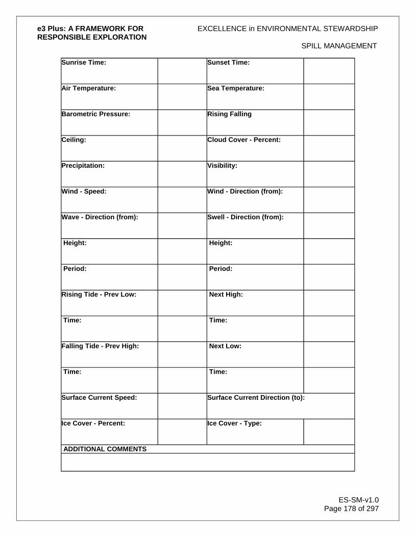
e3 Plus: A FRAMEWORK FOR EXCELLENCE in ENVIRONMENTAL STEWARDSHIP RESPONSIBLE EXPLORATION
SPILL MANAGEMENT
ES-SM-v1.0 Page 178 of 297
Sunrise Time:
Sunset Time:
Air Temperature:
Sea Temperature:
Barometric Pressure:
Rising Falling
Ceiling:
Cloud Cover - Percent:
Precipitation:
Visibility:
Wind - Speed:
Wind - Direction (from):
Wave - Direction (from):
Swell - Direction (from):
Height:
Height:
Period:
Period:
Rising Tide - Prev Low:
Next High:
Time:
Time:
Falling Tide - Prev High:
Next Low:
Time:
Time:
Surface Current Speed:
Surface Current Direction (to):
Ice Cover - Percent:
Ice Cover - Type:
ADDITIONAL COMMENTS

e3 Plus: A FRAMEWORK FOR EXCELLENCE in ENVIRONMENTAL STEWARDSHIP RESPONSIBLE EXPLORATION
SPILL MANAGEMENT
ES-SM-v1.0 Page 179 of 297
Contact Lists
It is the company‟s responsibility to obtain contact information for the jurisdiction in which the exploration site is located. All of this information can be obtained from the Web sites of various national, provincial, territorial, and municipal governments.

e3 Plus: A FRAMEWORK FOR EXCELLENCE in ENVIRONMENTAL STEWARDSHIP RESPONSIBLE EXPLORATION
WASTE MANAGEMENT
ES-WM-v1.0 Page 180 of 297
12.0 Waste Management
Waste includes those materials that are discarded, or are intended to be discarded. This section addresses the issue of waste management with the goal of leaving as light a footprint as possible in an exploration program. It describes the various categories of waste and gives guidance in assessing the management and disposal options that are available. All waste disposal activities require a permit from the local authorities, whether on-site or off-site. This may be issued by the Mines Department, the Environment Department or the local municipal government, and will vary from country to country (or even within countries). It is therefore essential that, during the planning stages of an exploration project, explorationists consult with local authorities to determine the permitting requirements, prior to making decisions about on-site/off-site waste disposal options. This information will also aid personnel involved in planning the exploration project to determine which types of materials to use. For example, if disposal regulations for certain materials are considered too onerous, alternate materials could be used. Different waste types require different treatment, so the first step in waste treatment is to define the waste type involved. Legal definitions for waste types have not been included in this section, as these will vary by location. Six descriptive categories for waste types are:
1. Recyclable general waste
2. Non-recyclable general waste
3. Recyclable special management waste
4. Non-recyclable special management waste
5. Recyclable dangerous waste (e.g., waste oil, waste antifreeze)
6. Non-recyclable hazardous waste Before setting up an exploration project, questions to ask in order to assess the waste that will be generated include the:
Number of people in the project
Presence of a site camp
Anticipated life of the project
Location of the project and possible environmental impacts
Determine specific features of the project area, including:
Temperature
Wind
Rainfall
Wildlife
Local environmental regulations and standards
In this process, take into account the activities to be undertaken in the project, which may include:
Trenching
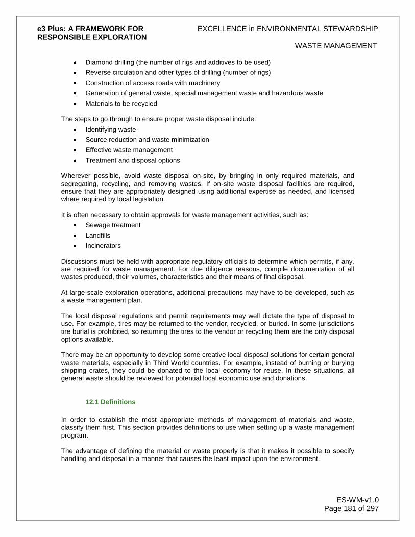
e3 Plus: A FRAMEWORK FOR EXCELLENCE in ENVIRONMENTAL STEWARDSHIP RESPONSIBLE EXPLORATION
WASTE MANAGEMENT
ES-WM-v1.0 Page 181 of 297
Diamond drilling (the number of rigs and additives to be used)
Reverse circulation and other types of drilling (number of rigs)
Construction of access roads with machinery
Generation of general waste, special management waste and hazardous waste
Materials to be recycled The steps to go through to ensure proper waste disposal include:
Identifying waste
Source reduction and waste minimization
Effective waste management
Treatment and disposal options
Wherever possible, avoid waste disposal on-site, by bringing in only required materials, and segregating, recycling, and removing wastes. If on-site waste disposal facilities are required, ensure that they are appropriately designed using additional expertise as needed, and licensed where required by local legislation. It is often necessary to obtain approvals for waste management activities, such as:
Sewage treatment
Landfills
Incinerators Discussions must be held with appropriate regulatory officials to determine which permits, if any, are required for waste management. For due diligence reasons, compile documentation of all wastes produced, their volumes, characteristics and their means of final disposal. At large-scale exploration operations, additional precautions may have to be developed, such as a waste management plan. The local disposal regulations and permit requirements may well dictate the type of disposal to use. For example, tires may be returned to the vendor, recycled, or buried. In some jurisdictions tire burial is prohibited, so returning the tires to the vendor or recycling them are the only disposal options available. There may be an opportunity to develop some creative local disposal solutions for certain general waste materials, especially in Third World countries. For example, instead of burning or burying shipping crates, they could be donated to the local economy for reuse. In these situations, all general waste should be reviewed for potential local economic use and donations.
12.1 Definitions
In order to establish the most appropriate methods of management of materials and waste, classify them first. This section provides definitions to use when setting up a waste management program. The advantage of defining the material or waste properly is that it makes it possible to specify handling and disposal in a manner that causes the least impact upon the environment.
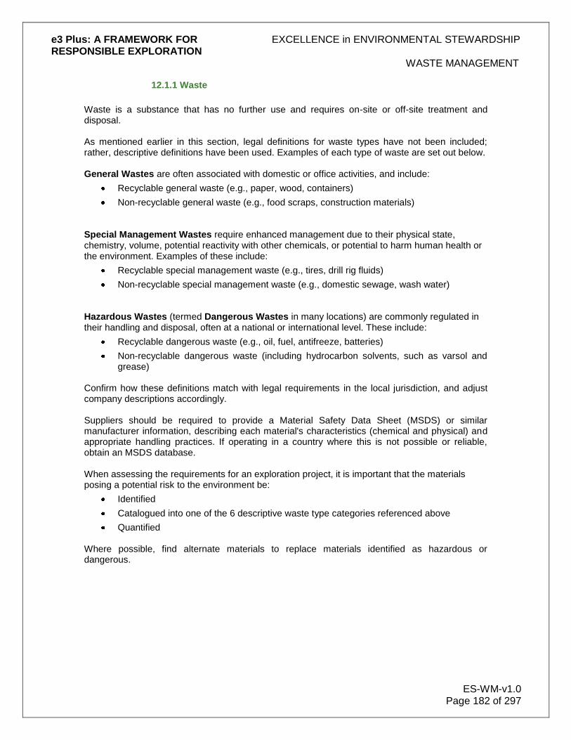
e3 Plus: A FRAMEWORK FOR EXCELLENCE in ENVIRONMENTAL STEWARDSHIP RESPONSIBLE EXPLORATION
WASTE MANAGEMENT
ES-WM-v1.0 Page 182 of 297
12.1.1 Waste
Waste is a substance that has no further use and requires on-site or off-site treatment and disposal. As mentioned earlier in this section, legal definitions for waste types have not been included; rather, descriptive definitions have been used. Examples of each type of waste are set out below. General Wastes are often associated with domestic or office activities, and include:
Recyclable general waste (e.g., paper, wood, containers)
Non-recyclable general waste (e.g., food scraps, construction materials)
Special Management Wastes require enhanced management due to their physical state, chemistry, volume, potential reactivity with other chemicals, or potential to harm human health or the environment. Examples of these include:
Recyclable special management waste (e.g., tires, drill rig fluids)
Non-recyclable special management waste (e.g., domestic sewage, wash water) Hazardous Wastes (termed Dangerous Wastes in many locations) are commonly regulated in their handling and disposal, often at a national or international level. These include:
Recyclable dangerous waste (e.g., oil, fuel, antifreeze, batteries)
Non-recyclable dangerous waste (including hydrocarbon solvents, such as varsol and grease)
Confirm how these definitions match with legal requirements in the local jurisdiction, and adjust company descriptions accordingly. Suppliers should be required to provide a Material Safety Data Sheet (MSDS) or similar manufacturer information, describing each material's characteristics (chemical and physical) and appropriate handling practices. If operating in a country where this is not possible or reliable, obtain an MSDS database. When assessing the requirements for an exploration project, it is important that the materials posing a potential risk to the environment be:
Identified
Catalogued into one of the 6 descriptive waste type categories referenced above
Quantified
Where possible, find alternate materials to replace materials identified as hazardous or dangerous.

e3 Plus: A FRAMEWORK FOR EXCELLENCE in ENVIRONMENTAL STEWARDSHIP RESPONSIBLE EXPLORATION
WASTE MANAGEMENT
ES-WM-v1.0 Page 183 of 297
A profile sheet such as the following may be of assistance in planning waste management:
Table 6: Sample Profile Sheet
PROFILE SHEET
DESCRIPTION: Grease
CHARACTERIZATION: Generally non-hazardous. Some greases may contain dangerous levels of toxic barium and lead. Metals content of each product should be evaluated prior to initial purchase.
Quantification: (project specific)
Sampling: Generally not required.
Analysis: Generally none. Use product information data sheets or material safety data sheets (MSDS) to evaluate. Unknown greases may require metals testing for lead and barium content.
MANAGEMENT:
Generation: (how and where waste is generated)
Site Storage: Store in closed containers away from heat, ignition sources and oxidizing agents.
Handling: No specific handling requirements.
Transportation: Package and transport according to local regulatory requirements.
Disposal: Recycle off-site.
Release Response: No specific response requirements.
Develop and implement an action plan to deal with the waste generated from the above identified materials. The details of this plan will depend on the size of the project and the anticipated duration of occupation.
12.1.2 Other Important Definitions
Other definitions that relate to waste management include:
Project. For the purposes of exploration, a project can be defined as a particular site where activities, possibly including diamond drilling, reverse circulation drilling, trenching, and line-cutting have joined a group of people together for a common goal. The word “project” encompasses all these activities and the related support system (e.g., eating and sleeping quarters).
Incinerate. Incinerate means to burn in a unit having engineered controls that permit the control of temperature and emissions. Note that various jurisdictions require permits for incinerating and may place limits on quantities or types of materials that can be incinerated.
Burn. Burn means to destroy by fire in the open air or in a container that is open to the air.
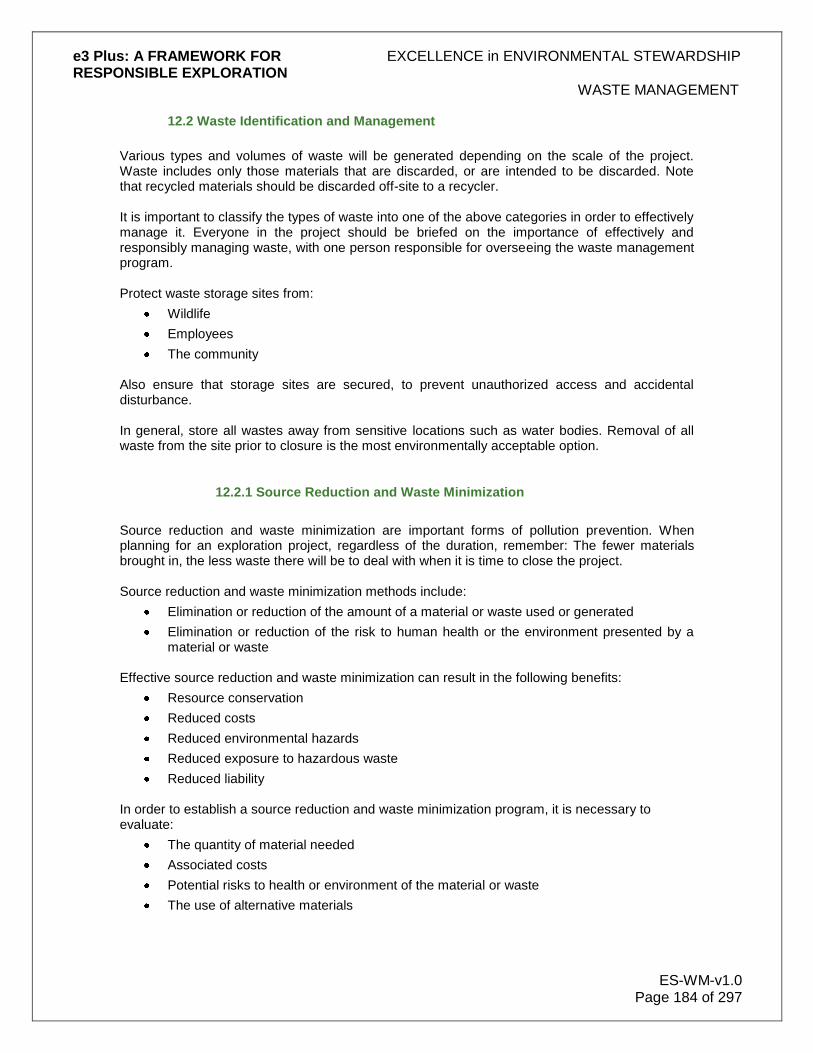
e3 Plus: A FRAMEWORK FOR EXCELLENCE in ENVIRONMENTAL STEWARDSHIP RESPONSIBLE EXPLORATION
WASTE MANAGEMENT
ES-WM-v1.0 Page 184 of 297
12.2 Waste Identification and Management
Various types and volumes of waste will be generated depending on the scale of the project. Waste includes only those materials that are discarded, or are intended to be discarded. Note that recycled materials should be discarded off-site to a recycler. It is important to classify the types of waste into one of the above categories in order to effectively manage it. Everyone in the project should be briefed on the importance of effectively and responsibly managing waste, with one person responsible for overseeing the waste management program. Protect waste storage sites from:
Wildlife
Employees
The community Also ensure that storage sites are secured, to prevent unauthorized access and accidental disturbance. In general, store all wastes away from sensitive locations such as water bodies. Removal of all waste from the site prior to closure is the most environmentally acceptable option.
12.2.1 Source Reduction and Waste Minimization
Source reduction and waste minimization are important forms of pollution prevention. When planning for an exploration project, regardless of the duration, remember: The fewer materials brought in, the less waste there will be to deal with when it is time to close the project. Source reduction and waste minimization methods include:
Elimination or reduction of the amount of a material or waste used or generated
Elimination or reduction of the risk to human health or the environment presented by a material or waste
Effective source reduction and waste minimization can result in the following benefits:
Resource conservation
Reduced costs
Reduced environmental hazards
Reduced exposure to hazardous waste
Reduced liability In order to establish a source reduction and waste minimization program, it is necessary to evaluate:
The quantity of material needed
Associated costs
Potential risks to health or environment of the material or waste
The use of alternative materials

e3 Plus: A FRAMEWORK FOR EXCELLENCE in ENVIRONMENTAL STEWARDSHIP RESPONSIBLE EXPLORATION
WASTE MANAGEMENT
ES-WM-v1.0 Page 185 of 297
When evaluating the associated costs to decide what to do, make sure to weigh the material purchase cost against the waste management cost.
12.2.1.1 Practices
After identifying priority materials and waste, determine specific practices for source reduction and waste minimization. This can include:
A responsible purchasing program
Modifications to current practices
Recycling Make purchasing choices based on informed decisions about the materials. Purchasing a biodegradable product in place of a non-biodegradable one, lessens the impact on the environment and on human health. Make a serious effort to identify alternatives to current practices.
12.2.1.2 Specific Examples
Listed below are some specific examples of source reduction and waste minimization that may be applied in an exploration program. Grease
Use non-toxic, or less harmful greases Oils and lubricating fluids
Where legislation allows, use these fluids in waste oil heaters Containers
Use materials completely before opening a new container
Use good material conservation procedures
Purchase in bulk
Purchase refillable containers
Where appropriate and allowed by legislation, reuse containers for other purposes
Support minimal packaging and the removal of unnecessary packaging by suppliers
12.2.2 General Waste
General waste is waste that does not meet the host country‟s hazardous (or dangerous) waste criteria. Do not assume to know what these criteria are, but verify them on a case-by-case basis. In a country whose norms fall short of the company's norms, use company criteria to define what is considered general waste. Some examples of general waste are:
Used office products, including general paper products
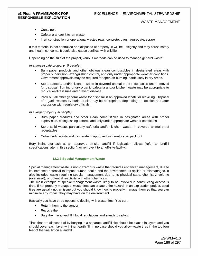
e3 Plus: A FRAMEWORK FOR EXCELLENCE in ENVIRONMENTAL STEWARDSHIP RESPONSIBLE EXPLORATION
WASTE MANAGEMENT
ES-WM-v1.0 Page 186 of 297
Containers
Cafeteria and/or kitchen waste
Inert construction or operational wastes (e.g., concrete, bags, aggregate, scrap) If this material is not controlled and disposed of properly, it will be unsightly and may cause safety and health concerns. It could also cause conflicts with wildlife. Depending on the size of the project, various methods can be used to manage general waste. In a small-scale project (< 5 people):
Burn paper products and other obvious clean combustibles in designated areas with proper supervision, extinguishing control, and only under appropriate weather conditions. Government approvals may be required for open air burning, particularly in dry areas.
Store cafeteria and/or kitchen waste in covered animal-proof receptacles until removed for disposal. Burning of dry organic cafeteria and/or kitchen waste may be appropriate to reduce wildlife issues and prevent disease.
Pack out all other general waste for disposal in an approved landfill or recycling. Disposal of organic wastes by burial at site may be appropriate, depending on location and after discussion with regulatory officials.
In a larger project ( 6 people):
Burn paper products and other clean combustibles in designated areas with proper supervision, extinguishing control, and only under appropriate weather conditions
Store solid waste, particularly cafeteria and/or kitchen waste, in covered animal-proof receptacles
Collect solid waste and incinerate in approved incinerators, or pack out Bury incinerator ash at an approved on-site landfill if legislation allows (refer to landfill specifications later in this section), or remove it to an off-site facility.
12.2.3 Special Management Waste
Special management waste is non-hazardous waste that requires enhanced management, due to its increased potential to impact human health and the environment, if spilled or mismanaged. It also includes waste requiring special management due to its physical state, chemistry, volume (oversized), or potential reactivity with other chemicals. The main example of special management waste likely to be involved in constructing access is tires. If not properly managed, waste tires can create a fire hazard. In an exploration project, used tires are usually not an issue but you should know how to properly manage them so that you can minimize any impact they may have on the environment. Basically you have three options to dealing with waste tires. You can:
Return them to the vendor.
Recycle them.
Bury them in a landfill if local regulations and standards allow.
Tires that are disposed of by burying in a separate landfill site should be placed in layers and you should cover each layer with inert earth fill. In no case should you allow waste tires in the top four feet of the final lift on a landfill.

e3 Plus: A FRAMEWORK FOR EXCELLENCE in ENVIRONMENTAL STEWARDSHIP RESPONSIBLE EXPLORATION
WASTE MANAGEMENT
ES-WM-v1.0 Page 187 of 297
Tires may also be used as construction materials during the exploration program, such as for holding signs and protecting areas from collision, but you are still required to handle them properly at site closure. Examples of special management waste include:
Domestic sewage and waste water.
Tires.
Other wastewater. Each of these is discussed in the subsections that follow.
12.2.3.1 Domestic Sewage and Wastewater
Sewage that has not been treated can create significant impacts on human health and the environment. Care should also be taken when disposing of other wastewater from showers, cleaning, and cooking. Depending on the scale of the project, there are various options to contain and treat or dispose of domestic sewage and wastewater. Remember that sewage and domestic wastewater should be kept separate from other wastes, and sewage systems should not be used for the disposal of other materials. Locate sewage and wastewater treatment facilities well away from sensitive environmental areas, and do not allow them to discharge directly into water bodies, such as streams or lakes. At a small scale project:
Collect sewage in a bagging system
Chemically treat sewage (e.g., in portable latrines)
Digs pits (pit privies) or develop other non-chemical latrines The bags used in a bagging system should be incinerated or removed from the site. Arrange for chemically treated effluent to be removed from the site by appropriate contractors. If this is not practicable, and government regulations allow, contain this effluent in a natural depression or pit. Only use pit privies for projects of short duration, and treat them at least once a day with chemicals (e.g., lime), to promote decay or reduce fly populations. Locate pit privies downslope of the camp, and downstream of any water intake location. When full, cover the pits with compacted soil or other appropriate material. Determine whether or not government approvals are required for this. At small sites, collect grey water from showers and other washing in a sump, or in some other manner, to minimize soil erosion. If local regulations allow, gradually disperse it over the ground surface. Locate the sump at least 15 m from a water body, and size it to hold 1.5 times the volume of water to be collected. Ensure that it does not discharge directly into a water body. If practical, use biodegradable soap and other environmentally friendly washing items. At a larger scale project:
A sewage system can be set up to handle both sewage and grey water
Additional expertise is likely to be required
Permits or approvals may be required under government regulations

e3 Plus: A FRAMEWORK FOR EXCELLENCE in ENVIRONMENTAL STEWARDSHIP RESPONSIBLE EXPLORATION
WASTE MANAGEMENT
ES-WM-v1.0 Page 188 of 297
A sewage system may entail a holding tank for collection of sewage, followed by either on-site treatment (e.g., a tile field with gradual soil infiltration), or haulage off-site to an appropriate treatment facility
Larger and more advanced sites may require aerobic treatment systems or a package reactor
12.2.3.2 Tires
If not properly managed, waste tires can create a fire hazard. In an exploration project, used tires are usually not an issue, but they should be dealt with properly to minimize any impact they may have on the environment. Basically, there are 3 options to dealing with waste tires:
Return them to the vendor
Recycle them
Bury them in a landfill, if local regulations and standards allow Tires that are disposed of by burying in a separate landfill site should be placed in layers, with each layer covered with inert earth fill. In no circumstances should waste tires be allowed in the top 4 feet of the final lift on a landfill. Tires may be used as construction materials during the exploration program (e.g., for holding signs and protecting areas from collision), but proper handling is still required at site closure.
12.2.3.3 Drill Rig Waste
Drill rigs produce a variety of wastes that require management. If possible:
Use biodegradable and non-toxic drill fluids and hole additives at all times
Recycle drill fluids If biodegradable products are not available, use lined sumps or above-ground storage tanks to provide containment, and allow solids to settle. Treat petroleum-based drilling fluids as petroleum waste. If an oily residue appears on the water surface, use measures to render it inaccessible to birds and wildlife and use absorbents to periodically remove residue. Various methods can be implemented to deal with drilling sludge and biodegradable fluids in an environmentally acceptable manner. They include the use of:
Sludge boxes
Containments constructed of filter fabric
Filtration control devices
Settling ponds
Straw bales
Geotextiles or other devices Provide an adequate closed circuit facility for drilling mud and flocculating agents. Alternatives may include:
A settling pool or sump a short distance downslope from the drill
A series of settling tanks adjacent to the drill

e3 Plus: A FRAMEWORK FOR EXCELLENCE in ENVIRONMENTAL STEWARDSHIP RESPONSIBLE EXPLORATION
WASTE MANAGEMENT
ES-WM-v1.0 Page 189 of 297
A drill cuttings/sludge material water filter Ensure that drill cuttings/sludge material from hydraulic stripping, and the discharge from any de-watering operation, does not enter any water source or flow uncontrolled. Dispose of diamond drill sludge collected in the sumps at an on-land site, sufficiently removed to prevent direct access of the material to a surface water course or water body. In certain locations, it may be necessary to recover drilling muds for treatment off-site. Backfill cuttings from a reverse circulation drill into the completed holes, if regulations allow. As this is not allowed in all locations, verify the requirements for specific abandonment practices with the regulatory bodies beforehand. Saline drilling waste is a special case that may require additional expertise. Generally, do not allow saline waste to come in contact with vegetation or non-saline water. In certain locations, ice drilling on a lake is a viable alternative to drilling in the warmer months. When drilling on the ice, use a heated sludge collector adjacent to the drill. This sludge box is composed of 2 heated compartments, 1 for runoff water and the other for collections of sediment residue. Clean out the residue compartment periodically, and put the residue on a waterproof tarpaulin on the ice and leave it to freeze. Once frozen, the sediment can be collected and disposed of in an appropriate location.
12.2.3.4 Other Wastewater
On occasion, exploration may require de-watering of existing inactive mine facilities (e.g., open pit, adit, shaft). De-watering is likely to require some form of wastewater treatment to minimize environmental impacts; this should be discussed with regulatory officials. As a minimum, prior to de-watering, collect representative water samples, and conduct chemical analyses on them to assess existing water quality. This will provide sufficient information to ascertain what form of treatment will be required. Typically, at least a lined settling pond will be required to settle any solids out of solution, prior to release into the environment. If acid-generating materials were exposed with the mine, or if the site was used for waste disposal, wastewater treatment could be significantly more complex. Ensure that any wastewater treatment facility is designed by appropriately experienced personnel, such as engineers. Recognize that de-watering of mine facilities for exploration purposes may impose new environmental liabilities on the company, and obtain appropriate advice before proceeding.
12.2.4 Hazardous Waste
Hazardous (or dangerous) waste is waste meeting a host country‟s or other chosen hazardous waste criteria. It can be a source of significant legal liability when improperly managed or released into the environment. Ensure that crisis management policies and procedures are in place in case there is an accident. It is important to identify all hazardous waste by keeping a comprehensive inventory list, and to have methods for managing it.
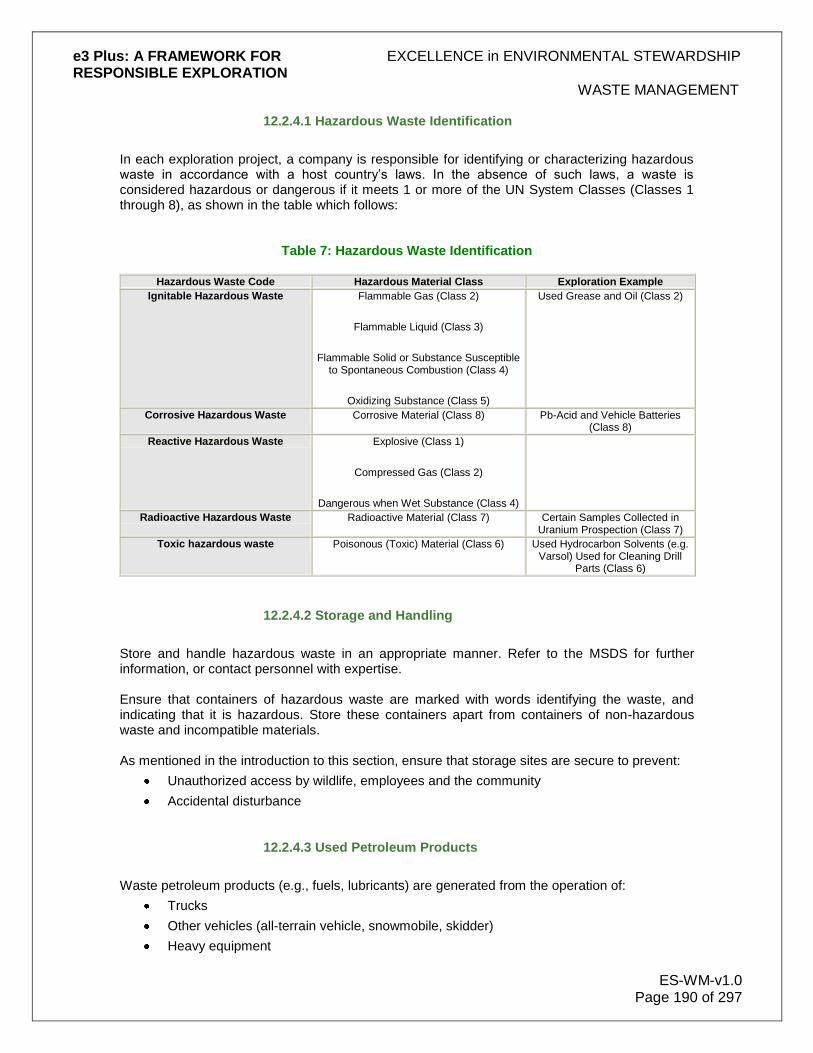
e3 Plus: A FRAMEWORK FOR EXCELLENCE in ENVIRONMENTAL STEWARDSHIP RESPONSIBLE EXPLORATION
WASTE MANAGEMENT
ES-WM-v1.0 Page 190 of 297
12.2.4.1 Hazardous Waste Identification
In each exploration project, a company is responsible for identifying or characterizing hazardous waste in accordance with a host country‟s laws. In the absence of such laws, a waste is considered hazardous or dangerous if it meets 1 or more of the UN System Classes (Classes 1 through 8), as shown in the table which follows:
Table 7: Hazardous Waste Identification
Hazardous Waste Code Hazardous Material Class Exploration Example
Ignitable Hazardous Waste Flammable Gas (Class 2)
Flammable Liquid (Class 3)
Flammable Solid or Substance Susceptible to Spontaneous Combustion (Class 4)
Oxidizing Substance (Class 5)
Used Grease and Oil (Class 2)
Corrosive Hazardous Waste Corrosive Material (Class 8) Pb-Acid and Vehicle Batteries (Class 8)
Reactive Hazardous Waste Explosive (Class 1)
Compressed Gas (Class 2)
Dangerous when Wet Substance (Class 4)
Radioactive Hazardous Waste Radioactive Material (Class 7) Certain Samples Collected in Uranium Prospection (Class 7)
Toxic hazardous waste Poisonous (Toxic) Material (Class 6) Used Hydrocarbon Solvents (e.g. Varsol) Used for Cleaning Drill
Parts (Class 6)
12.2.4.2 Storage and Handling
Store and handle hazardous waste in an appropriate manner. Refer to the MSDS for further information, or contact personnel with expertise. Ensure that containers of hazardous waste are marked with words identifying the waste, and indicating that it is hazardous. Store these containers apart from containers of non-hazardous waste and incompatible materials. As mentioned in the introduction to this section, ensure that storage sites are secure to prevent:
Unauthorized access by wildlife, employees and the community
Accidental disturbance
12.2.4.3 Used Petroleum Products
Waste petroleum products (e.g., fuels, lubricants) are generated from the operation of:
Trucks
Other vehicles (all-terrain vehicle, snowmobile, skidder)
Heavy equipment
e3 Plus: A FRAMEWORK FOR EXCELLENCE in ENVIRONMENTAL STEWARDSHIP RESPONSIBLE EXPLORATION
WASTE MANAGEMENT
ES-WM-v1.0 Page 191 of 297
Waste petroleum products are not typically considered hazardous waste, but they may be in certain jurisdictions. Management of these products is crucial to maintaining a safe environment and reducing environmental impacts. Manage used petroleum products according to the host country‟s laws. As a general rule, the materials should be stored on-site in labelled, competent, covered containers, placed in an impervious secondary containment (e.g., larger container, lined berm) wherever possible or practical, and away from flame sources, including cigarettes. Protect all storage from accidental impact, and take care to ensure that the quantity of used petroleum products stored on-site is limited, as this material is a fire hazard. Possible management options to use include:
Storage in competent, labelled containers, with these containers periodically returned to the vendor for recycling.
Regeneration for reuse on-site (e.g., for heating, in explosives mixtures) or off-site.
Burning for energy recovery on-site or off-site, but only if a chemical analysis shows that it is acceptable for burning, and usually only in high temperature furnaces designed for that purpose.
Incineration.
Disposal of petroleum-contaminated materials (rags, trash, filters, and spill absorbents) and soil in approved non-hazardous waste landfill, preferably off-site. Draining of materials into appropriate containers prior to disposal, and dealing separately with the liquids and solids is often preferred.
Containerization and disposal in a designated area of an approved solid waste landfill. Ensure that the materials do not become compacted in such a way that leakage occurs.
12.2.4.4 Used Antifreeze
Used antifreeze (ethylene glycol) is derived from draining various cooling systems. It does not always meet criteria for hazardous materials, but in some jurisdictions it does, and it is important to verify this. Like used petroleum products, used antifreeze can cause environmental damage and health concerns if not managed properly. Some options for managing waste antifreeze are:
Storage in competent, labelled containers, with these containers periodically returned to the vendor for recycling
Containerization and disposal in an approved landfill, likely requiring shipment off-site
12.2.4.5 Treatment
Where allowed by law, the most desirable form of treatment after recycling and waste minimization is on-site treatment. At smaller projects, hazardous waste would likely only be stored for later off-site disposal. In larger scale projects, 1 or several of the options listed above may be considered, in consultation with specialists and local regulatory authorities. Potential treatments may include:
Incineration of organic waste
Neutralization of corrosive waste

e3 Plus: A FRAMEWORK FOR EXCELLENCE in ENVIRONMENTAL STEWARDSHIP RESPONSIBLE EXPLORATION
WASTE MANAGEMENT
ES-WM-v1.0 Page 192 of 297
Solidification of liquid waste (usually after chemical treatment)
Controlled chemical reaction of reactive waste
Many of these activities require supervision by properly qualified people. If they are not on-site for supervision, ensure that they are consulted before making any important high-impact decisions.
12.2.4.6 Transportation
When transporting hazardous waste off-site, do so in compliance with the host country‟s laws. As a minimum, each off-site shipment should be accompanied by a form that includes the following information:
Waste name
Generation source
Quantity
Temporary storage area
Container type, labelling and packaging
Shipment date
Shipper
Destination
Name and coordinates of person responsible
Basic emergency response or MSDS It is important to set up a document filing system to retain records of shipments, and to implement a system of verification of receipt of goods at the destination.
12.2.4.7 Off-Site Management
Before any hazardous waste is shipped to an off-site location:
Ensure that crisis management policies and procedures are in place
Consider the environmental and/or human health risks if waste is spilled or mismanaged en route, or at the proposed site
Investigate the qualifications and history of the shipping company
Have a knowledgeable person from the company visit the proposed site
Determine whether the host country‟s regulators have approved the shipping company and the disposal site
Have a knowledgeable person verify legal implications if the shipper or facility do not comply with environmental requirements
12.2.4.8 On-site Waste Management Facilities
On-Site Waste Management Facilities Sometimes, due to the remoteness of the exploration site, waiting to take waste off-site at the termination of the program is not practical. In this case, you should consider on-site disposal and handling facilities in consultation with personnel with expertise and appropriate regulatory officials.
e3 Plus: A FRAMEWORK FOR EXCELLENCE in ENVIRONMENTAL STEWARDSHIP RESPONSIBLE EXPLORATION
WASTE MANAGEMENT
ES-WM-v1.0 Page 193 of 297
Depending on the complexity and scale of the exploration activities, it may be appropriate for you to designate one area for waste management. This location can have
A designated burn or incinerating area.
An area for sorting recyclables.
A location for petroleum waste storage and draining of petroleum-related materials.
A landfill/disposal pit. Remember that on-site disposal facilities require design, permitting, operation and closure in compliance with host country laws. When choosing the site for waste handling disposal, you should observe as many of the following criteria as possible:
Location as far as practicable from human and environmental receptors, especially water bodies.
Easy accessibility in all kinds of weather to company vehicles, yet inaccessible to local residents.
Foundation of low permeability soil, such as clay, and tight rock.
Suitable for appropriate liners.
Flat topography requiring minimal grading.
Located on company's property.
As small an area of impact as possible while providing sufficient capacity.
Conducive to closure monitoring and maintenance.
Landfills are prime sources of material in some parts of the world. Care is needed particularly where chemical waste is involved to ensure a physically stable foundation. You must not place the disposal site near
Stream channels, seeps, bogs and flood-plains.
Sites susceptible to landslides or avalanches.
Sites with foundations susceptible to failure.
Protected areas, wetlands, critical habitat.
Historic places.
Coastal or river locations susceptible to erosion. In areas of shallow groundwater, disposal sites should be lined with compacted clay or synthetic liners. Non-hazardous Waste Landfill The purpose of a landfill is to dispose of non-hazardous solid wastes through land filling when they cannot reasonably be removed from site. You should observe the following guidelines:
Designate waste wood, paper, steel, plastics and rubber as landfill materials. Most of these materials should be considered for recycling as a first option if facilities exist
within reasonable proximity to the site.
Do not permit dangerous wastes, liquid wastes and food-related wastes to be disposed of at the landfill.

e3 Plus: A FRAMEWORK FOR EXCELLENCE in ENVIRONMENTAL STEWARDSHIP RESPONSIBLE EXPLORATION
WASTE MANAGEMENT
ES-WM-v1.0 Page 194 of 297
Do not permit burning at the landfill.
Dedicate an area for tires.
Cover and contour waste materials on a regular basis using clean fill.
Cover and contour rubber less frequently than other wastes to allow an opportunity for these materials to be reused.
In the simplest form, and where allowed by government regulations, the on-site landfill may be a trench or series of trenches excavated in deep, dry soil that you progressively fill from one end to the other, with garbage covered each day to reduce wildlife issues. Once filled, you should cover the trench with compacted soil or other appropriate material, often from the excavation of another adjacent trench. At larger sites, the landfill may become complex and you may require engineering input for such items as leachate collection. You should ensure that, if required, you obtain government approvals for complex landfills that might be required for large exploration operations. Dangerous Waste Landfill If your project will be short term in nature, all hazardous waste should be stored as mentioned in the previous section and transported off-site. If your project is of longer duration, you should verify the on-site storage period that is allowed by regulation and waste should be removed before project completion.
Waste Rock Disposal
Waste rock may be an issue. Certain types of rock containing sulphides may have the potential to generate acid on exposure to air and water. You should always analyze waste rock for acid generating and neutralizing potential and soluble metals prior to determining final storage locations. When choosing a location for a waste rock disposal site, you should:
Locate it on flat or stable slopes to ensure mass stability of the waste rock.
Consider and minimize potential visual impacts, particularly on hillsides
Avoid locations that will require re-handling over time, excluding closure activities. You should not locate a waste rock disposal site at or near:
Stream channels, whether active or not.
Known springs or seeps.
Other environmentally sensitive locations. You should store inert waste rock and other mineral wastes in a manner that minimizes environmental impacts. Typically this will require storing the material in as compact an area as possible, either in stockpiles or, in the case of drill cuttings, over a limited surface area. If you store unconsolidated materials in a humid environment you may require establishing a collection pond down slope of the stockpile to ensure that sediment is not released into the environment. If you know or suspect that waste rock or other mineral wastes (such as scrap core and cuttings) will be acid generating, special handling may be required, particularly in humid environments. In most circumstances at the exploration stage, only small quantities of material are likely to be produced. In any case, you should minimize the extraction of acid generating waste rock and its exposure to air and water.

e3 Plus: A FRAMEWORK FOR EXCELLENCE in ENVIRONMENTAL STEWARDSHIP RESPONSIBLE EXPLORATION
GUIDELINES FOR URANIUM EXPLORATION
ES-UR-v1.0 Page 195 of 297
13.0 Guidelines for Radiation Protection during Exploration for Uranium
These e3 Plus Guidelines for Radiation Protection during Exploration for Uranium have been developed to assist exploration companies protect employees and others from radiation while exploring for uranium. The PDAC hopes that these Guidelines will prove useful to exploration companies in the creation or refinement of their own corporate guidelines. The Guidelines are intended to be a living document, updated and expanded as new information becomes available. To keep these Guidelines as current as possible, the PDAC welcomes comments and suggestions, particularly regarding website resources to be added to the References and Links section. These Guidelines have been prepared in Canada and, as a result largely reflect conditions and situations found in that country. The PDAC welcomes contributions from e3 Plus users who can provide new content from other regions of the world. The PDAC thanks everyone who has been of assistance in the creation of these Guidelines and would like to give particular thanks to the following:
Alex Buchnea of SCIMUS
Sally Howson and colleagues at Aurora Energy Resources
Roger Wallis of Roger Wallis & Associates
Mark Wittrup and colleagues at Cameco
Peter Wollenberg and colleagues at AREVA
13.1 Uranium and Radioactivity
13.1.2 Radiation Basics
All material is made up of atoms, which in turn are made up of a nucleus, consisting of neutrons and protons (accounting for more than 99.95% of the mass), and electrons spinning around in orbits (accounting for 99.999% of the volume). Material is radioactive when its nucleus is unstable and seeks to achieve stability by the emission of radioactive particles called gamma rays (no mass), beta particles (high energy electrons), alpha particles (two protons and two neutrons) and neutrons. These particles are very energetic and can knock electrons of atoms out of their orbit, creating ions. Thus, they are called ionizing radiation.
Figure 43:* Ionizing Radiation (Radiation with enough energy to remove an electron from its atom).

e3 Plus: A FRAMEWORK FOR EXCELLENCE in ENVIRONMENTAL STEWARDSHIP RESPONSIBLE EXPLORATION
GUIDELINES FOR URANIUM EXPLORATION
ES-UR-v1.0 Page 196 of 297
The following figures describe the three types of radiation – alpha, beta and gamma – which are significant in uranium exploration, and their properties.
Figure 44:* Alpha Particle α.
Figure 26:* Beta Particle β.

e3 Plus: A FRAMEWORK FOR EXCELLENCE in ENVIRONMENTAL STEWARDSHIP RESPONSIBLE EXPLORATION
GUIDELINES FOR URANIUM EXPLORATION
ES-UR-v1.0 Page 197 of 297
Figure 46:* Gamma Ray γ.
*Illustrations for Figures 1-4 are used with permission from the RadGrad course materials, available from the Michigan Section of the American Nuclear Society (MI-ANS)
1 Sv = 1 million microsieverts (µSV); absorbed dose in tissue (J/kg) corrected for the biological effects of radiation; unit of
radiation dose in International System of Units (SI) 2 Bq = 1 disintegration per second; activity expressed in International System of Units (SI)
The two basic units of measure in radiation protection are the sievert (Sv)
1 (indicating the dose
received from a radioactive material) and the becquerel (Bq)2 (indicating the amount of
radioactivity in a material, in disintegrations/second). There are two types of radiation exposure:
1 External radiation exposure
The radiation source is located outside the body 2 Internal radiation exposure, which results from the intake of radioactive materials through:
Inhalation
Ingestion
Absorption through the skin or through wounds
13.1.2 Properties of Uranium
Uranium is a common, naturally occurring radioactive element. It is a normal part of rocks, soil, and water, and it occurs in nature in the form of minerals, never as a metal. Uranium metal is silver-coloured with a grey surface and is nearly as strong as steel. Uranium is a metal of high density (18.9 g/cm
3). The earth's crust contains an average of about 3 ppm (= 3 g/t) uranium;
seawater contains approximately 3 ppb (= 3 mg/t). Natural uranium is a mixture of three types or isotopes called U-234, U-235, and U-238, together with all of its decay products (also referred to as its daughter products or progeny). In a typical sample of natural uranium, almost all the mass

e3 Plus: A FRAMEWORK FOR EXCELLENCE in ENVIRONMENTAL STEWARDSHIP RESPONSIBLE EXPLORATION
GUIDELINES FOR URANIUM EXPLORATION
ES-UR-v1.0 Page 198 of 297
(99.27%) consists of atoms of U-238. Less than 1% (about 0.72%) of the mass consists of atoms of U-235, and a very small amount (0.0054%) is U-234. All three are the same chemical, but they have different radioactive properties. U-238 and U-235 are the parent nuclides of two independent decay series, while U-234 is a decay product of the U-238 series.
Table 8: Properties of the Natural Uranium Isotopes and Isotopic Composition of Natural Uranium*
Properties of the Natural Uranium Isotopes*
U-234 U-235 U-238
Half-life 244,500 years 703.8 • 106
years 4.468 • 109 years
Specific activity 231.3 MBq/g 80,011 Bq/g 12,445 Bq/g
Isotopic Composition of Natural Uranium*
U-234 U-235 U-238 Total
Atom % 0.0054% 0.72% 99.275% 100%
Weight % 0.0053% 0.711% 99.284% 100%
Activity % 48.9% 2.2% 48.9% 100%
Activity in 1 g Unat 12,356 Bq 568 Bq 12,356 Bq 25,280 Bq
Since U-235 is such a small contributor to radiation from uranium ore, only the U-238 decay series is discussed in this section.
Table 9: Uranium-238 Decay Series*
Uranium-238 Decay Series*
Nuclide Half-Life Radiation
U-238 4.468 • 109
years alpha
Th-234 24.1 days beta
Pa-234m 1.17 minutes beta
U-234 244,500 years alpha
Th-230 77,000 years alpha
Ra-226 1,600 years alpha
Rn-222 3.8235 days alpha
Po-218 3.05 minutes alpha
Pb-214 26.8 minutes beta
Bi-214 19.9 minutes beta
Po-214 63.7 microseconds alpha
Pb-210 22.26 years beta
Bi-210 5.013 days beta
Po-210 138.378 days alpha
Pb-206 stable -
* Uranium tables used with permission of the WISE Uranium Project
Most of the radioactive decay products emit a gamma ray as well as the indicated particles. In natural uranium, these decay series generally are in secular equilibrium. This means that in 1 g of

e3 Plus: A FRAMEWORK FOR EXCELLENCE in ENVIRONMENTAL STEWARDSHIP RESPONSIBLE EXPLORATION
GUIDELINES FOR URANIUM EXPLORATION
ES-UR-v1.0 Page 199 of 297
natural uranium, each nuclide of the U-238 series has an activity of 12,356 Bq. In the various processing steps of nuclear fuel production, the equilibrium is disrupted. In a uranium ore deposit, secular equilibrium exists between U-238 and its decay products. The equilibrium may be somewhat disturbed by geochemical migration processes in the ore deposit. An ore grade of 1% U3O8 is equivalent to 0.848% uranium, and 1 million lbs U3O8 are equivalent to 385 metric tonnes of uranium. The grade of ore varies – depending on the type of deposit – with average grades of commercially viable deposits ranging between about one-tenth of one percent to over 20% U3O8 in some parts of the Athabasca basin in northern Saskatchewan. The radiation is virtually trapped underground; exposures are only possible if contaminated groundwater circulating through the deposit migrates to a work environment. Though it can travel through underground fissures, radon from deep deposits is of no concern for surface exploration, since it decays before it can reach the surface. The alpha radiation of the eight alpha emitting nuclides contained in the U-238 series presents a radiation hazard on ingestion or inhalation of uranium ore (dust) and radon. The gamma radiation (mainly of Pb-214 and Bi-214) together with the beta radiation of Th-234, Pa-234m, Pb-214, Bi-214, and Bi-210, presents an external radiation hazard. For ingestion and inhalation, the chemical toxicity of uranium also has to be taken into account.
15.1.3 Geological and Climatic Conditions
Depending on the region in which exploration is taking place, different geological and climatic conditions will affect the nature of the hazards during exploration and the methods used in protecting workers and the environment from these hazards. Some of the various conditions are addressed in these Guidelines; however, not all conditions are included at this stage. Further conditions may need to be addressed in future. The hazards addressed in these Guidelines encompass the following conditions:
Diamond drilling, usually several hundred metres deep in hard rock, requiring water cooling
Drilling in winter conditions in northern latitudes In progress to be included in these Guidelines in future are:
Drilling in surficial deposits in arid climatic conditions, using rotary air blast drilling
Drilling in wet tropical areas These conditions delineate the various hazards that are associated with uranium drilling; other conditions likely would fall within this outline.
15.2 Exposure Limits
Exploration in Canada is governed by the provinces and the territories. The International Atomic Energy Agency (IAEA) has set radiation exposure limits for radiation workers and for members of the public that are widely used as a general guideline by regulators. These limits are adopted by the nuclear regulatory bodies in the various member countries – for example, the Canadian Nuclear Safety Commission (CNSC) and the Australian Radiation Protection and Nuclear Safety Agency. A person normally engaged in work with radiation and who has the potential of receiving exposure above the public limit is designated as a Nuclear Energy Worker (NEW)
3 by the CNSC,

e3 Plus: A FRAMEWORK FOR EXCELLENCE in ENVIRONMENTAL STEWARDSHIP RESPONSIBLE EXPLORATION
GUIDELINES FOR URANIUM EXPLORATION
ES-UR-v1.0 Page 200 of 297
a special designation that requires specific controls on the worker. In Canada, such a worker on a provincial level is typically designated as an occupational worker. Exposure (dose) is calculated by the sum of the gamma (mSv) plus RnP (radon progeny) as it impacts Working Level Months (WLM) plus LLRD (long-lived radioactive dust – internal long-lived alpha exposure):
Effective Dose (mSv) = Gamma (mSv) + 5 (RnP WLM) + 20 (intake in becquerels/2800)
Where 4 WLM = 20 mSv, and the LLRD ALI (annual limit of intake) = 2800 Bq The table below gives the annual exposure limits included in the Radiation Protection Regulations of Canada‟s Nuclear Safety and Control Act*. These limits represent the sum of exposure for all types of radiation – external, internal, and radon gas and its progeny.
Table 10: CNSC Whole Body Dose Limits*
CNSC Whole Body Dose Limits*
Person Exposure Period Effective Dose (mSv)
Nuclear Energy Worker (NEW) One-year dosimetry period 50
Five-year dosimetry period 100
Pregnant NEW Balance of pregnancy 4
General public (non-NEW) One calendar year 1
*The annual exposure limits cited were correct as of October 2008. While NEW exposure levels vary by job, the average yearly radiation exposure of a monitored NEW in Canada is generally less than 1 mSv. This includes all NEWs, not only those working in exploration. A pregnant NEW has to inform the employer as soon as she is aware of the pregnancy. Uranium exploration workers are usually classified as non-NEWs – unless the grades and conditions result in the potential for higher doses – and have the same exposure limits as members of the general public. Exposure to radon progeny (RnP) is measured in Working Level Months (WLM) – one WLM is the exposure to 2.08 x 10
-5 J of RnP for one month. The limit for exposure to radon in the
absence of any other sources of radiation is four WLM in one year. 3
A Nuclear Energy Worker (NEW) is defined as a person with “a reasonable probability that the person may receive a dose (occupational) of radiation that is greater than the prescribed limit for the general public” (i.e., 1 millisievert per year, or 1 mSv/yr; 1mSv/yr = 1,000 µSv/yr). A NEW is informed in writing of their NEW designation and a written acknowledgement is obtained from the worker and kept in central records. During radiation protection training, a NEW is informed of the risks associated with radiation to which they may be exposed in the course of their work, and the applicable dose limits. A NEW is informed of their doses at least quarterly, and their doses are recorded in the National Dose Registry.
13.3 Radiation Measurement Instrumentation
None of the human senses can detect ionizing radiation directly; thus, in order to properly implement a radiation protection strategy, radiation detection instrumentation is very important.

e3 Plus: A FRAMEWORK FOR EXCELLENCE in ENVIRONMENTAL STEWARDSHIP RESPONSIBLE EXPLORATION
GUIDELINES FOR URANIUM EXPLORATION
ES-UR-v1.0 Page 201 of 297
The meter generally used for measuring gamma radiation fields during drilling programs is a high volume sodium iodide (NaI) scintillometer. Workers involved in uranium exploration can use these scintillometers to make field measurements of external gamma radiation, measured in counts per second (cps), calibrated to Cesium-137. The measured value of radiation will depend on the sample size and the distance the measurement is taken from the sample. Examples of the time required for obtaining a 10 μSv exposure by handling various grades of ore (all counts and doses at 1 m from source) are included in the following chart:
Table 11: Examples of the time required for obtaining a 10 μSv exposure
CPS µSv/hr Hours for 10
µSv % U3O8 Comment
200 - 450 0.05 - 0.15 - <0.01 Background levels
600 - 700 0.5 20 20 0.05 Maximum waste rock
1000 1* 10 0.1 Radiation protection
procedure trigger
3000 3 3.3 0.3 Start of high grade ore
10000 10 1 1 High grade ore
*Some companies may use a different trigger level.
A contamination meter, such as a pancake Geiger counter with a thin mica window, measuring in counts per minute (cpm)4, is used to measure radioactive contamination of clothing, hands, and other exposed areas of the body, tools and equipment, and working areas. This detector is sensitive to beta radiation as well as gamma radiation and is primarily used to monitor personnel and equipment, in order to prevent the spread of contamination. It is considerably more sensitive to beta radiation than a gamma meter.
Figure 47: Contamination Meter Ludlum Model 12 Pancake G-M Detector*
* Photographs used with permission of Ludlum Measurements Inc.

e3 Plus: A FRAMEWORK FOR EXCELLENCE in ENVIRONMENTAL STEWARDSHIP RESPONSIBLE EXPLORATION
GUIDELINES FOR URANIUM EXPLORATION
ES-UR-v1.0 Page 202 of 297
RnP is also generated by uranium ore; however, the radon levels expected during exploration work in an outdoor environment should be within the range of natural background levels other than winter drilling in cold climates in enclosed spaces. If drill rig platforms and the core and splitting shacks are well ventilated, no accumulation of radon progeny above background levels is expected, except in large accumulations of the highest grade ores. In cases where significant amounts of high grade core are being examined in the core shack, or high grade ore is being stockpiled in an indoor environment, considerable amounts of radon progeny can develop. Radon monitoring should be conducted to determine whether routine monitoring is required if heated areas are enclosed and insulated during winter operations. This can be done either using a passive radon detector, such as an E-perm or PICO-RAD, Landauer RadTrak, Safety Institute of Canada radon monitor or an electronic detector (e.g., a scintillometer, ion chamber, alpha spectrometer). Apart from winter operations, in most cases routine radon monitoring is not considered to be necessary during the exploration activities, aside from confirmation sampling and specific area monitoring to determine background with radon monitors such as E-perms. In cases in which radon measurements indicate above background levels, personal alpha dosimeters (PAD) should be worn. These are active devices which sample the air and measure both RnP and particulate alpha concentrations. In a core shack containing mineralized core, there will be RnP above background levels. As long as these working levels (WL) remain below Health Canada indoor radon guidelines (200 Bq/m3, 0.29 WL), no further action is required. If RnP levels are greater than 0.03 WL, an assessment of the working environment should be carried out to ensure that there is adequate ventilation. Reasonable efforts should be made to remove the contaminant from the working environment before employing dosimetry. Continued area monitoring of the impacted area(s) should also be conducted to assess worker exposures. In most cases, PADs would only be required if annual doses from RnP exceed 5 mSv. If RnP levels are greater than 0.03 WL, an assessment of the working environment to ensure that there is adequate ventilation is highly recommended. Reasonable efforts should be made to remove the contaminant from the working environment before employing dosimetry. Continued area monitoring of the impacted area(s) should also be conducted to assess worker exposures. In most cases, PADs would only be required if annual doses from RnP could exceed 5 mSv. Long-term measurement of the dose from external radiation is available from individual thermoluminescent dosimeters (TLDs) supplied by a designated dosimetry service. Workers are required to use TLDs. These are worn as a badge or ring (for extremity dose measurements) and record the cumulative external dose received. They are submitted regularly (monthly or quarterly) to the designated dosimetry service, which reports the results. The badge is typically used in the field to measure the whole body dose. TLDs do not provide real time measurement of external radiation; these badges are “passive” and must be sent to the dosimetry service for results. Electronic personal dosimeters (EPDs), or other direct reading devices (DRDs), can also be worn by individual workers, to give a direct reading of the accumulated external gamma dose. These can also have dose and dose rate alarms. Long-lived radioactive dust (LLRD) must also be considered in exploration activities. 3 Contamination is typically measured in counts per minute (cpm)
13.4 Radiation Hazards during Exploration
The hazards discussed in this section are those that can be expected in the conditions described in Section Geological and Climatic Conditions
e3 Plus: A FRAMEWORK FOR EXCELLENCE in ENVIRONMENTAL STEWARDSHIP RESPONSIBLE EXPLORATION
GUIDELINES FOR URANIUM EXPLORATION
ES-UR-v1.0 Page 203 of 297
Potential health hazards during uranium exploration come from:
External radiation – mainly gamma and beta to the eye and hands
Radon progeny (RnP) build-up in enclosed spaces from samples and drill-core
LLRD particles from splitting or drilling, that can be inhaled or ingested. During initial exploration and baseline studies, the expected radiation hazard is mainly from external gamma radiation from the uranium mineralization in the disturbed areas (e.g., waste rock piles and tailings areas associated with previous mining activities, cuttings from previous drill locations), in mineralized rock outcropping, and in specimens collected by geologists in the field. As long as normal hygiene practices are following, there is a minimal likelihood of radioactive contamination on body parts (mainly hands), clothing, and tools. The exception is when underground workings are re-evaluated for possible economic grade ore. Radon build-up in old underground workings could be a significant hazard requiring ventilation prior to entry. During the drilling program, the possibility of contamination of equipment and personnel from the cuttings during the drilling depends on the type of drilling employed. If diamond drilling with cooling water is used, dust levels are generally low, and thus the inhalation hazard is low. The potential for contamination spread can be minimized by controlling the wet cuttings. Such control can happen through the use of a cyclone or filtration system. Radioactive cuttings should be disposed off down the hole after completion of drilling, if this is possible. Another option would be to store the radioactive cuttings in appropriate containers for later disposal or removal. Storage of such materials must be within designated areas. With rotary air blast drilling – usually employed above the water table and without water – dust can be a significant hazard and must be controlled. External gamma radiation from the drill cores or cuttings (especially where cores and cuttings are laid out for examination), or logging core is a potential hazard for both types of drilling. Stockpiles of core boxes with the greatest potential gamma hazard would generally be in the vicinity of the core shack or core storage areas. Airborne contamination (LLRD) can also occur during the core splitting operations. A manual core splitter or a rock saw can be used in this operation – the amount of dust generated will depend on the amount of water used on the rock during splitting. Rock that is dry cut using a rock saw has the potential to generate large amounts of airborne contamination. In most cases, hazards due to the accumulation of radon gas and its decay products are typically insignificant, since the drill sites and core stocks are expected to be in open air and the core shack facilities are expected to be well ventilated. The exception is during winter operations in northern climates in which the core shacks and drill rig platforms are heated and air exchange rates are limited. However, the use of exhaust fans to exchange the air in closed buildings even in wintertime is highly recommended. As radon is infinitely soluble in water, it may be a concern in enclosed settling tanks or if ore is intersected, in return water at a drill (especially for high grade deposits.) Contamination controls and the use of protective clothing by workers, including gloves and respirators during core splitting, should limit the ingested and inhaled radioactivity to insignificant levels, while safety glasses provide protection against beta radiation.
13.5 Radiation Protection Principles
It is the joint responsibility of the employer and the employee to ensure that adequate radiation protection measures are in place at all times. To ensure that radiation exposure to workers is well below the dose limits noted earlier in Section Radiation Measurement Instrumentation an ALARA (as low as reasonably achievable) program is central to a Radiation Protection Program, to

e3 Plus: A FRAMEWORK FOR EXCELLENCE in ENVIRONMENTAL STEWARDSHIP RESPONSIBLE EXPLORATION
GUIDELINES FOR URANIUM EXPLORATION
ES-UR-v1.0 Page 204 of 297
ensure dose levels, as well as social and economic factors, are taken into account. ALARA is implemented through the use of:
Engineering controls (e.g., layout of drill sites, core storage and cuttings management)
Layout of core shack area and core stockpile
Administrative controls (e.g., personnel movement restrictions, monitoring requirements)
Personnel protective equipment (gloves, glasses, respirators)
Certain principles outlined below are useful in controlling exposure to external gamma radiation, as well as internal beta and alpha radiation from radioactive contamination.
13.5.1 Protection from External Exposure to Gamma Radiation
There are powerful methods that are simple to implement and can result in drastic reductions in worker exposure. Four main principles are employed to reduce dose from external gamma radiation:
1. Time – restrict time in contact with radioactive material; dose received is proportional to time spent
2. Distance – dose is reduced by square of distance (i.e., dose at 2 m is ¼ dose at 1 m)
3. Shielding – use core with low radiation fields to shield core with high fields, or place appropriate shielding material between oneself and the source of radiation, to lower the radiation dose received
4. Source reduction – remove radioactive core from high occupancy areas as soon as possible
13.5.2 Protection from Internal Radiation (Contamination Control)
The single most important thing to do is to ensure that the contaminated area is separated from clean areas. Protective gear should be kept in the contaminated area and personnel should clean up before moving to a clean area, eating or smoking. Controlling the spread of contamination is the most effective way of controlling doses from internal beta and alpha radiation. Simple protective equipment (e.g., coveralls, gloves, safety glasses, lead aprons, respirators), work practices, and procedural controls (e.g., no eating, no smoking) can be used in areas where there is known radioactive material. Monitoring can be used to prevent the spread of contamination from these areas. Establish areas known as contamination control zones and monitor procedures to restrict movement of personnel and equipment from these areas. This system is described in detail 13.6 Radiation Protection Program
Principles of radiation protection from internal exposure to radiation:
1. Wear appropriate protective clothing
2. Wear approved and properly fitted respiratory protection
3. Follow radiation safety procedures
4. Practice good hygiene
5. Monitor for contamination when leaving a restricted area
6. Appropriately dispose of contaminated clothing, equipment, and materials
7. Take appropriate steps to minimize the spread of contamination

e3 Plus: A FRAMEWORK FOR EXCELLENCE in ENVIRONMENTAL STEWARDSHIP RESPONSIBLE EXPLORATION
GUIDELINES FOR URANIUM EXPLORATION
ES-UR-v1.0 Page 205 of 297
13.6 Radiation Protection Program
In order to adequately protect the workers from radiation during the exploration and drilling programs, a Radiation Protection Program (RPP) must be designed and implemented and should be in place at all times. However, the program‟s success can only be achieved through the full cooperation of all workers. As a result, all workers should receive RPP training, to ensure they understand all information in the program. In Canada exploration activities (with the exception of some advanced exploration) are not regulated by the CNSC but rather by the provinces and territories. Exploration is considered a NORM (naturally occurring radioactive materials) related activity, except during the transport of mineralized core where CNSC and Transport regulations apply. The Radiation Protection Regulations of Canada‟s Nuclear Safety and Control Act specify the following for a licensed facility (other jurisdictions have similar regulations): “Every licensee shall implement a radiation protection program and shall, as part of that program…keep the amount of exposure to radon progeny and the effective dose and equivalent dose received by and committed to persons as low as is reasonably achievable, social and economic factors being taken into account, through the implementation of
1. management control over work practices,
2. personnel qualification and training
3. control of occupational and public exposure to radiation, and 4. planning for unusual situations.”
Although an exploration and drilling program is not a licensed activity, the above RPP is deemed a minimum requirement. For a progressive approach, see the Canadian Guidelines in NORM. A program to be implemented during the exploration and drilling phases should include:
•Training of all field personnel
Adequate supervision to ensure radiation protection (RP) procedures are developed and implemented, including workplace monitoring (e.g., RnP and LLRD)
Personnel dosimetry
External gamma radiation monitoring and protection
Contamination control
Environmental controls
In addition, appropriate records of the above elements must be kept as indicated further below. Note: As RP requirements depend on the grade of the mineralization being drilled, typically implementation of RP controls has been needed only when the drilled core exceeds a certain radiation field. Below this level, no controls are necessary other than periodic monitoring. The action level* recommended for the initiation of RP controls is 1 µSv/hr at 1 m distance/height or 10 µSv/hr on contact from an accumulation of freshly drilled core, as indicated on a gamma meter. *Action level is a guideline to all project personnel, based on previous field experience.
13.6.1 Responsibilities
It is recommended that a Radiation Safety Officer (RSO) be placed in charge of the RPP. The RSO must be qualified in radiation protection and is responsible for developing the RPP procedures, work instructions, and forms, and ensuring that they are properly implemented. In addition, the RSO ensures that workers receive training. Any modifications to the program are

e3 Plus: A FRAMEWORK FOR EXCELLENCE in ENVIRONMENTAL STEWARDSHIP RESPONSIBLE EXPLORATION
GUIDELINES FOR URANIUM EXPLORATION
ES-UR-v1.0 Page 206 of 297
made by the RSO. The RSO may report to either the Project Manager or the person in charge of overseeing the day-to-day Environmental, Health, and Safety (EHS) activities (i.e., overseeing the implementation of the RPP in the field). The EHS Manager delegates someone to be in charge of issuing and collecting all dosimeters and radiation detection instrumentation and ensuring any necessary daily briefings are conducted. Implementation at drill sites and core shacks (e.g., routine radiation measurements) is the responsibility of the Project Geologist on duty. The people mentioned above form the Radiation Protection (RP) Management Team. The RP Management Team‟s responsibilities include:
Creating corporate RP guidelines* regarding uranium exploration and EHS protection
Requiring all workers involved in handling mineralized materials use the protective devices, measures, and procedures outlined in corporation‟s RP guidelines, to minimize radiation exposure, and requiring that all necessary RP procedures are routinely applied
Directing all workers so that all government regulations with regard to safe work practices are strictly adhered to
Providing education and training to all personnel with respect to RP guidelines requirements
Advising personnel of potential hazards associated with site operations
Providing for routine radiological monitoring of the exploration facilities, specifically sites where radioactive materials (e.g., drill core, rock samples etc.) are being handled and where actions are required
Requiring the proper use of appropriate personal protective equipment by all on-site personnel
Requiring that any work practices or conditions that may result in injury or unnecessary radiation exposure are corrected immediately following identification
Overseeing the processes for the transportation of mineralized core or rock samples All workers involved in exploration and drilling programs (including regular staff, contractors, and visitors) are required to:
Attend all necessary training and pre-job safety briefing sessions
Be familiar with and adhere to RP guidelines, and report any deviations from anticipated conditions affecting worker safety to the EHS Manager or equivalent for action
Perform only those tasks that they believe they can do safely, and immediately report any accidents and/or unsafe conditions to management
Some examples of possible routine daily RP tasks are noted below; daily RP tasks would also include monitoring of potentially contaminated surfaces such as the tops of core logging tables.
Table 12: Routine daily Radiation Protection (RP) Tasks and responsibility
ROUTINE DAILY RADIATION PROTECTION (RP) TASKS AND RESPONSIBILITY
RP Tasks Description RP Responsibility
Start of the Day
Get TLDs Each worker is required to take his/her TLD from the designated rack. Company to provide TLD; worker to wear it
Use protective
clothing as
necessary
Normal working clothes and gloves necessary for most days. If certain
tasks require additional PPE, EHS Manager or designate will specify. EHS Manager or designate and worker
Pre-job briefing RP considerations for planned work reviewed, radiation field levels
reviewed, RP responsibilities assigned if different from previous day. EHS Manager or designate and worker
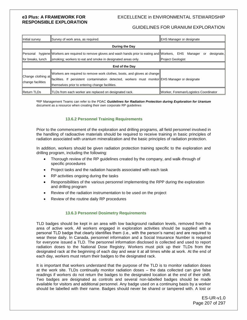
e3 Plus: A FRAMEWORK FOR EXCELLENCE in ENVIRONMENTAL STEWARDSHIP RESPONSIBLE EXPLORATION
GUIDELINES FOR URANIUM EXPLORATION
ES-UR-v1.0 Page 207 of 297
Initial survey Survey of work area, as required. EHS Manager or designate
During the Day
Personal hygiene
for breaks, lunch
Workers are required to remove gloves and wash hands prior to eating and
smoking; workers to eat and smoke in designated areas only.
Workers, EHS Manager or designate,
Project Geologist
End of the Day
Change clothing at
change facilities
Workers are required to remove work clothes, boots, and gloves at change
facilities. If persistent contamination detected, workers must monitor
themselves prior to entering change facilities.
EHS Manager or designate
Return TLDs TLDs from each worker are replaced on designated rack. Worker, Foreman/Logistics Coordinator
*RP Management Teams can refer to the PDAC Guidelines for Radiation Protection during Exploration for Uranium document as a resource when creating their own corporate RP guidelines
13.6.2 Personnel Training Requirements
Prior to the commencement of the exploration and drilling programs, all field personnel involved in the handling of radioactive materials should be required to receive training in basic principles of radiation associated with uranium mineralization and the basic principles of radiation protection. In addition, workers should be given radiation protection training specific to the exploration and drilling program, including the following:
Thorough review of the RP guidelines created by the company, and walk-through of specific procedures
Project tasks and the radiation hazards associated with each task
RP activities ongoing during the tasks
Responsibilities of the various personnel implementing the RPP during the exploration and drilling program
Review of the radiation instrumentation to be used on the project
Review of the routine daily RP procedures
13.6.3 Personnel Dosimetry Requirements
TLD badges should be kept in an area with low background radiation levels, removed from the area of active work. All workers engaged in exploration activities should be supplied with a personal TLD badge that clearly identifies them (i.e., with the person‟s name) and are required to wear these daily. In Canada, personnel information and a Social Insurance Number is required for everyone issued a TLD. The personnel information disclosed is collected and used to report radiation doses to the National Dose Registry. Workers must pick up their TLDs from the designated rack at the beginning of each day and wear it at all times while at work. At the end of each day, workers must return their badges to the designated rack. It is important that workers understand that the purpose of the TLD is to monitor radiation doses at the work site. TLDs continually monitor radiation doses – the data collected can give false readings if workers do not return the badges to the designated location at the end of their shift. Two badges are designated as controls and several non-labelled badges should be made available for visitors and additional personnel. Any badge used on a continuing basis by a worker should be labelled with their name. Badges should never be shared or tampered with. A lost or

e3 Plus: A FRAMEWORK FOR EXCELLENCE in ENVIRONMENTAL STEWARDSHIP RESPONSIBLE EXPLORATION
GUIDELINES FOR URANIUM EXPLORATION
ES-UR-v1.0 Page 208 of 297
damaged badge should immediately be brought to the attention of the supervisor your supervisor so that a replacement badge can be assigned. The reporting period for the TLDs is quarterly. Each quarter, the TLDs are replaced with new ones and those that have been worn, the control TLDs, and any unused TLDs are returned to the designated dosimetry service for measurement by management. In Canada, the company is required to notify workers of their accumulated doses, once the results have been received from the designated dosimetry service. Electronic personal dosimeters (EPDs) can also be worn, but are not normally required unless the primary criterion of 1 µSv/hr at 1 m distance/height is exceeded. If DRDs are being assigned, log sheets should be completed daily, so that worker exposures can be tracked and if necessary used to estimate worker doses to gamma radiation.
13.6.4 External Gamma Radiation
A potentially significant hazard can be presented by external gamma radiation exposure from uranium mineralization (depending on the grade of ore) and radioactive sources in exploration equipment. Adequate monitoring of sites with above-background level of radiation is essential. Prior to conducting any work such as drilling and core handling, a gamma survey should be conducted and the areas with gamma fields greater than 1 µSv/hr on a gamma meter at a distance of 1 m should be identified to workers. Areas with significant radiation levels that are adjacent to work locations in which workers may be routinely present (e.g., the core storage areas, any areas where radioactive samples are stored, trenches and waste rock dumps with elevated radiation levels), must be clearly identified to workers (e.g., signs posted at core shack and storage areas). Workers should conduct gamma surveys in each work area prior to commencement of work and whenever conditions change substantially (i.e., as mineralized core accumulates in the core stocks). Gamma surveys should also be conducted at the completion of drilling. Mitigation measures should be taken during drilling to ensure that dose levels are below 1 µSv/hr when measurable contamination is present.
As noted in Section 13.5.1 Protection from External Exposure to Gamma Radiation in order to
apply the ALARA principle and minimize the dose, the four strategies of time, distance, shielding,
and source reduction are used.
The action level recommended for the initiation of the contamination control procedures is 1
µSv/h at 1 m distance/height
13.6.5 Contamination Control Procedures
Contamination control is achieved by maintaining a separation between areas that have radioactive contamination and those that do not. It is also achieved by careful contamination monitoring and the use of protective clothing (e.g., gloves, coveralls). During the preliminary exploration phase, the risk of contamination is expected to be small and only present during the handling of mineralized material. Workers must wear cotton or equivalent gloves when handling radioactive materials. If the mineralization is above the action level, workers must monitor themselves and tools prior to leaving the work area, using the procedures described in Section Contamination Monitoring of Contamination Control Zones below. If mineralized material is handled, monitoring of workers should also be done prior to breaks or lunch. Contamination control procedures should also include routine monitoring of work surfaces
e3 Plus: A FRAMEWORK FOR EXCELLENCE in ENVIRONMENTAL STEWARDSHIP RESPONSIBLE EXPLORATION
GUIDELINES FOR URANIUM EXPLORATION
ES-UR-v1.0 Page 209 of 297
and floors; core shacks should be thoroughly cleaned daily. Contamination can build up slowly over time. Good housekeeping will also help minimize the buildup and spread of contamination. During the drilling program, the potential for contamination on the drill rig platform is small, as diamond drilling utilizes water and there is no build-up of dust, regardless of the grade of ore being recovered. The main potential sources of contamination are the wet cuttings collecting under the platform and rock chips that may fall on the platform during the extraction of core from the core tube. Poly tanks are metal tanks with removable plastic “wiffles” which separate the coarse cuttings from the drill water. Poly tanks are often used to collect cuttings when drilling on the ice. If these tanks are not available a mud tank or lined sump can be used to collect drill cuttings. The purpose of collecting the cuttings from the mineralized zones is to monitor them and based on results dispose of the cuttings in an appropriate manner as outlined in these Guidelines. As a conservative measure and to control environmental emissions, the wet cuttings should be routed to a sump from the poly tanks when drilling in the mineralized zone. The use of a dual filtration system, allowing the routing of radioactive cuttings into one containment and the routing of non-radioactive cuttings into a separate system is encouraged. Radioactive cuttings may be disposed of down the drill hole at the termination of the drilling if feasible, or stored in appropriate containers until proper disposal or removal from the work site. The drill rig platform is constantly being washed to prevent the accumulation of cuttings for conventional safety reasons, which ensures that the potential is low for contamination of workers and equipment in the work area. The workers use coveralls and gloves, which are generally left at the change facilities. There is typically no need to designate the drill rig platform as a contamination control zone during wet drilling, unless periodic measurements so indicate (especially when the action level is exceeded). The presence of radioactive cuttings has to be checked after the removal of the drill platform. Proper disposal of any such cuttings is required, as per previous descriptions. During rotary air blast (RAB) drilling however, considerable dust can be generated – cuttings are dry and the potential for contamination spread is large. This is particularly true in arid climates. Active RAB sites should be designated as contamination control zones, until monitoring and any decontamination, if necessary, has been completed. In the core shack area – whenever radioactive core is being handled – the core logging tables, floor, and the core splitting facility have the greatest potential for contamination. Other potential sources of radioactive contamination are spills that may occur when emptying the drip pan under the core-cutting saw. Core logging and splitting facilities should be designated contamination control zones. The use of a respirator during core splitting or cutting is recommended. It would be good practice, even during wet cutting, that the worker wears at least an N95 filter mask. Workers must keep the change facilities free from contamination by following the procedures in these Guidelines. These are also designated contamination control zones. In order to control the spread of potential contamination, contamination monitoring should be conducted periodically in these contamination control zones, in the manner described and as required, on all workers and equipment in these zones. In addition, workers are required to wear proper personal protective equipment (PPE) in the work area.
13.6.5.1 Contamination Monitoring of Contamination Control Zones

e3 Plus: A FRAMEWORK FOR EXCELLENCE in ENVIRONMENTAL STEWARDSHIP RESPONSIBLE EXPLORATION
GUIDELINES FOR URANIUM EXPLORATION
ES-UR-v1.0 Page 210 of 297
When the mineralization grade is below action level in the contamination control zones identified above, the drill platforms (only under certain conditions), the core logging and core splitting facilities, and the change facilities should be monitored periodically. Designated “Clean Areas”, such as work bunkhouses and the dining area, should also be checked routinely. If contamination is detected, the monitoring frequency should be adjusted to weekly or daily, until the source of the contamination is identified or there is no contamination for three successive weeks. When the mineralization grade is above the action level, these areas should be monitored on a weekly basis, or daily if contamination is routinely detected. The monitoring should be conducted as follows:
Ensure that the contamination meter is turned on, that the battery is charged, and that the reading is not sensitive to movement of the cable attached to the probe. Observe the background reading for 20 seconds using the slow response time and record average reading. This should be performed in a low background area away from potential sources of contamination.
Switch to the fast response time, and slowly move the contamination meter 1 cm above surface area of floors and tables, particularly along floor cracks, and along the edges and corners of the room, and any other areas that may have a potential for the accumulation of contaminated material.
If the meter reads 100 cpm above background level, clean the area and repeat the measurement until the level is acceptable; if the reading remains high or if the background in the area is above 300 cpm, take a swipe
5 of an area of at least 300 cm
2
and monitor the swipe in an area with a background level count of less than 100 cpm
Occasional wash water and fines or sweepings, if generated, will be minimal and will not cause increased background level radiation; if contamination levels are high (above 1000 cpm), the wash water and fines or sweepings can be temporarily collected in a sump or other small containment area located near the monitored zones, until they are transferred to the secure containment areas where elevated cuttings are safely disposed.
5 To swipe, use a clean cloth to remove any surface material from an area of at least 300 cm²,
take it to an area of low background, and take a count with a beta and/or alpha sensitive contamination meter. Examples of Monitoring and Control of Workspace Contamination Associated with Exploration Activities
Weekly Monitoring Tasks by Geologists and Geotechnicians During Core Examination and Logging
Conduct a source check of the pancake Geiger probe and count rate meter. Replace probe and meter unit if there is no response or low response to the check source. Document results:
1. Swipe all tabletops and walkways between tables in the core logging facilities for removable contamination.
2. Place the swipes in a plastic bag, take a count, and record results.
3. If removable contamination levels exceed 5.0 Bq/cm2 (beta) or 0.5 Bq/cm2 (alpha) on a
300 cm2 surface, the tables will have to be cleaned as described in Step 5 under Daily

e3 Plus: A FRAMEWORK FOR EXCELLENCE in ENVIRONMENTAL STEWARDSHIP RESPONSIBLE EXPLORATION
GUIDELINES FOR URANIUM EXPLORATION
ES-UR-v1.0 Page 211 of 297
Monitoring Tasks above. Note: Surface should be cleaned if any contamination 100 cpm or more above background is detected.
4. Conduct swipe checks again following cleaning and record results.
5. If removable contamination persists at levels above the values stated in Step 6 under Daily Monitoring Tasks above, dispose of tabletops and walkway floorboards, and replace with clean material.
6. Until the time of removal from the exploration activity, store the ashes and other contaminated materials in a designated and marked area.
Daily Monitoring Tasks by Geologists and Geotechnicians During Core Examination and Logging
Drill core is often examined on plywood trestle tables inside or, weather permitting, just outside the core logging facility:
1. Monitor tabletops and the walkway floors between tables for radioactivity, as core boxes are removed, and prior to bringing in new core for examination. This is done by direct check with the pancake Geiger probe and count rate meter (Ludlum 12).
2. To perform a direct check, first move the range switch of the rate meter to the “Battery” position and ensure that the battery voltage levels are within the acceptable range.
3. Move the range switch to the lowest range. The meter should register a background level count rate of 30 to 120 counts per minute (cpm)*. No mineralized core should be in the area when contamination monitoring is being conducted.
4. Move the Geiger probe over the plywood surface being monitored and note areas of elevated contamination above background levels.
5. Clean any tabletop surface with levels greater than 1000 cpm on direct check by damp wiping, to reduce levels below 1000 cpm.
6. If levels cannot be reduced below the 1000 cpm levels, replace the tabletops with new plywood. (Note: Tabletops can be lined with sheets of easily decontaminated material to facilitate clean up).
* Measurement of contamination levels is typically done in counts per minute (cpm)
15.6.5.2 Personnel Monitoring in Work Areas
If contamination is detected in any of the change facilities on a routine basis, an investigation should be conducted to determine the source of the contamination. If the source can be identified, personnel contamination monitoring should be established in a designated monitoring area, either adjacent to the source (e.g., the core splitting shack, the drill platform), in an area free of radioactive contamination and with low radiation fields. The radiation field should be recorded, as well as the background level reading on the contamination survey meter. If possible, the background level reading on the contamination meter should be less than 300 cpm. Note: If the source cannot be readily identified, worker monitoring should be conducted prior to entry into the change facilities.

e3 Plus: A FRAMEWORK FOR EXCELLENCE in ENVIRONMENTAL STEWARDSHIP RESPONSIBLE EXPLORATION
GUIDELINES FOR URANIUM EXPLORATION
ES-UR-v1.0 Page 212 of 297
The monitoring areas and the change areas must be kept free of radioactive contamination. When personnel monitoring is necessary, workers are required to perform the following checks with the contamination meter:
Ensure that the meter is turned on, that the battery is charged, and that the reading is not sensitive to movement of the cable attached to the probe
Observe the background level reading for 20 seconds, using the slow response time
Switch to the fast response time and pass the survey meter – at a distance of about 1 cm – over the soles of shoes and hands (without gloves) Note: If the work area is particularly dusty, use the meter to monitor coveralls as well.
Ensure that the reading is less than 100 cpm above background level. If it is higher, identify the area and wash with water to decontaminate. Repeat the process until the reading is within acceptable limits. Report any issues to the EHS Manager or designate.
The change facilities are areas where workers change from their work clothes into clean clothes and vice versa. The floors and benches of change facilities should be monitored on a regular basis (at least once a month) to ensure they are free of contamination. The work clothes should also be monitored periodically (as determined by the EHS Manager) to ensure there is no build-up of contamination. If there is a persistent need to decontaminate the floors, bench, and/or personnel, the monitoring frequencies should be increased and the clothes monitored and, if necessary, decontaminated by washing in water. Safely dispose wash water in a secure containment area. Periodic monitoring of dining areas should also be carried out, to ensure no contamination is present. Personnel decontamination can be done by cleansing with a cloth or, if necessary, washing. Contaminated clothing can also be washed in water.
13.6.5.3 Personal Protective Equipment
Personal Protective Equipment (PPE) required for RP during the exploration program when handling of mineralized material consists mainly of gloves (i.e., cotton); in the case of rock cuttings, PPE consists of respirators (or dust masks) and coveralls. During the drilling program, in addition to required PPE – coveralls, gloves, as well as safety boots and hard hats (on drill rigs) – the use of safety glasses is recommended during the examination of mineralized rock and drill core, in order to protect the eyes from rock shards, as well as beta and alpha radiation. A respirator should be worn during the core splitting. The Radiation Safety Officer (RSO) can provide further guidance on PPE and make adjustments, as required. A lead apron is also provided to the Geologists and technicians who examine high grade cores.
13.6.6 General Radiation Safety Guidelines
The most important considerations in handling mineralized materials are personal hygiene and the prevention of contamination leaving the control zones on one‟s person or clothing. Good personal hygiene is the best way to prevent ingestion of any radioactive material. All personnel are required to apply the following safety measures when working on an uranium exploration project:
Wear gloves (i.e., cotton) when handling soil, silt; wear a dust mask as well as gloves when collecting rock, or when taking chip samples

e3 Plus: A FRAMEWORK FOR EXCELLENCE in ENVIRONMENTAL STEWARDSHIP RESPONSIBLE EXPLORATION
GUIDELINES FOR URANIUM EXPLORATION
ES-UR-v1.0 Page 213 of 297
Wash hands and hair daily, and wash clothes regularly
Do not bring any rock or drill core into contact with lips or mouth
Avoid drinking water from open drill holes
Keep any open wounds bandaged
Wash hands after handling rock or drill core, and before eating or smoking, to prevent ingestion of radioactive materials
Do not eat, drink, or smoke in the vicinity of areas with elevated radiation levels
Gloves and safety glasses must be worn, when working with mineralized drill core
Safety glasses are mandatory when examining drill core, to protect the eyes from beta radiation
A respirator must be used when splitting core
Reduce dust by wetting the area with water whenever necessary and available; in arid regions, use other dust suppression methods
If the 1 µSv/hr action level has been exceeded in the drill core, periodically check field clothes with contamination meter; if the reading is greater than 100 cpm above background level, bag clothes on-site for laundering
Ensure that there is proper ventilation in the core logging facility, to avoid inhalation of radioactive materials (e.g., radon gas, dust); taking seasonal conditions into account, always take steps to maximize ventilation (e.g., opening doors and windows, turning on exhaust fans to circulate the air)
Always work in well-ventilated environment or monitor periodically for radon build-up; if the 1 µSv/hr action level has been exceeded in the drill core, monitor work areas on a regular basis with contamination meters
Control the spread of contamination at all times by following field protocols as outlined in these Guidelines
All workers are required to wear their thermoluminescent dosimeters (TLDs)
If levels above the criterion are encountered, exploration workers examining and logging mineralized cores must wear a direct reading dosimeter (DRD) in addition to their TLD; drill contractors who handle and box the core are required to wear a TLD alone
Distance is the best way to reduce exposure to radioactivity; store any radioactive core well away from the main camp area (i.e., >30 m away) and downwind from the main wind direction
Mineralized core should also be stored at least 30 m away from any body of water
Store only a minimum amount of core boxes inside an enclosed core logging facility while logging the core
Ensure that the core storage area is well posted with appropriate signs to indicate the presence of radioactive material
Long-term core storage areas should be secured with appropriate radiation warning signs
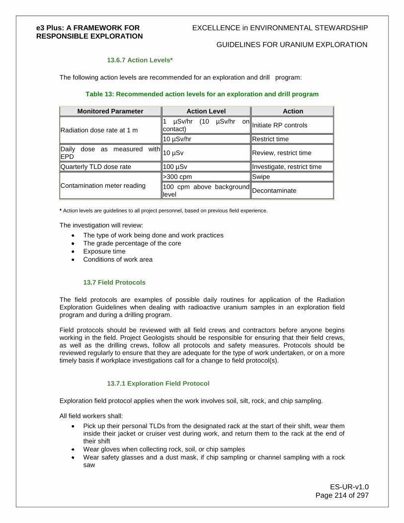
e3 Plus: A FRAMEWORK FOR EXCELLENCE in ENVIRONMENTAL STEWARDSHIP RESPONSIBLE EXPLORATION
GUIDELINES FOR URANIUM EXPLORATION
ES-UR-v1.0 Page 214 of 297
13.6.7 Action Levels*
The following action levels are recommended for an exploration and drill program:
Table 13: Recommended action levels for an exploration and drill program
Monitored Parameter Action Level Action
Radiation dose rate at 1 m
1 µSv/hr (10 µSv/hr on contact)
Initiate RP controls
10 µSv/hr Restrict time
Daily dose as measured with EPD
10 µSv Review, restrict time
Quarterly TLD dose rate 100 µSv Investigate, restrict time
Contamination meter reading
>300 cpm Swipe
100 cpm above background level
Decontaminate
* Action levels are guidelines to all project personnel, based on previous field experience.
The investigation will review:
The type of work being done and work practices
The grade percentage of the core
Exposure time
Conditions of work area
13.7 Field Protocols
The field protocols are examples of possible daily routines for application of the Radiation Exploration Guidelines when dealing with radioactive uranium samples in an exploration field program and during a drilling program. Field protocols should be reviewed with all field crews and contractors before anyone begins working in the field. Project Geologists should be responsible for ensuring that their field crews, as well as the drilling crews, follow all protocols and safety measures. Protocols should be reviewed regularly to ensure that they are adequate for the type of work undertaken, or on a more timely basis if workplace investigations call for a change to field protocol(s).
13.7.1 Exploration Field Protocol
Exploration field protocol applies when the work involves soil, silt, rock, and chip sampling. All field workers shall:
Pick up their personal TLDs from the designated rack at the start of their shift, wear them inside their jacket or cruiser vest during work, and return them to the rack at the end of their shift
Wear gloves when collecting rock, soil, or chip samples
Wear safety glasses and a dust mask, if chip sampling or channel sampling with a rock saw
e3 Plus: A FRAMEWORK FOR EXCELLENCE in ENVIRONMENTAL STEWARDSHIP RESPONSIBLE EXPLORATION
GUIDELINES FOR URANIUM EXPLORATION
ES-UR-v1.0 Page 215 of 297
Remove work gloves before eating or smoking
Ensure that sample storage areas, or previously contaminated areas with mineralized core, and/or rock, and other high gamma areas (>1 μSv/hr at 1 m) are clearly identified to personnel
Before entering a vehicle, aircraft, or helicopter at the end of the day, workers shall:
Place all samples in plastic sample bags
If action level of 1 μSv/hr at 1 m distance/height has been exceeded, monitor hands, soles of shoes, and clothing with a contamination meter prior to boarding; if the monitoring indicates contamination, then decontaminate
Store sample bags in a baggage compartment that is removed by personnel by 1 m at a minimum
At the base camp, workers shall:
Store samples in designated area – the area should be well ventilated and marked and be a minimum of 30 m away from any work area
Remove and store field clothes and gear in change facilities
Return TLDs to designated rack
Not store any field clothing or samples in the office or living quarters
• Wash and dry field clothing only in designated washing machines
13.7.1.1 Change Facilities and Camp Dining Area Monitoring Program
The following monitoring program should be conducted in change facilities and in the camp dining area:
• The change facilities and dining area should be monitored with a contamination meter at least once every month and at the end of the program with a contamination meter • If contamination is found in any of the areas, the contaminated areas should be cleaned and the contamination monitoring frequency increased in the field • The field protocols should be reviewed by the EHS Committee • The monitoring and decontamination protocols in Section Contamination Control Procedures should be followed
13.7.2 Drill Personnel Protocol
Drill protocols will be reviewed with the drill crew. The drill foreman is responsible for ensuring that drill crews follow all protocols and safety measures. Drillers should use the normal safety equipment (e.g., coveralls, boots, gloves) when dealing with mineralized drill core. All drill workers shall:
Pick up their personal TLDs from the designated rack in the morning and wear them inside their jacket or cruiser vest at all times during their shift, and return their TLDs to the designated rack at the end of their shift
Ensure that no field clothing or samples are stored in the living quarters or office
Wash and dry field clothing only in a designated washing machine Drill Crew Contamination Monitoring Program:

e3 Plus: A FRAMEWORK FOR EXCELLENCE in ENVIRONMENTAL STEWARDSHIP RESPONSIBLE EXPLORATION
GUIDELINES FOR URANIUM EXPLORATION
ES-UR-v1.0 Page 216 of 297
The Project Geologist and EHS Manager or designate will be responsible for monitoring the core shacks, the camp change facilities, checking the monitoring area for contamination, and ensuring that the drill crew are following proper protocols as indicated in Section Contamination Control Procedures, whenever implementation is necessary
13.7.2.1 Drill Site Environmental Protection Protocol
Prior to drilling, the Project Geologist or EHS Manager will fill in the Drill Site Check List, documenting pre-drilling site conditions. Background levels of radiation will be recorded with a gamma meter. Background radiation levels should be measured on a close grid pattern at the drill location and potentially impacted surrounding areas (e.g., low or runoff areas). If possible, field measurements should be linked to a GPS coordinate. The following actions also are necessary to ensure appropriate on-site environmental protection:
Once mineralization has been intersected, the mineralized core will be stored 10-20 m from the drill platform or behind large boulders, prior to transporting to the core shack
When diamond drilling through mineralized zones, a closed circuit facility (i.e., poly tanks) should be used to recycle water through settling tanks or drums
When RAB drilling is employed in mineralized zone in dry soil above the water table, appropriate dust suppression techniques should be employed
In wet drilling, once the cuttings settle out, the water can be recycled and drained into a sump or soak-away pit, located down slope from the drill and 50 m from streams or lakes, in accordance with applicable government guidelines
After a drill hole is completed, monitor the residues (e.g., drill mud, cuttings, soils) using a gamma meter; when monitoring a site the gamma meter should be held 1 m away from the cuttings; any residues with a gamma reading greater than 1 µSv/hr at 1 m distance/height should be either covered with soil in a pit, or returned down the drill hole
If no further investigations in the drill hole are necessary, the upper 30 m of bedrock or the entire depth of the hole – whichever is less – should be grouted; grouting of mineralized sections is highly recommended
If significant ore is encountered, consider grouting the entire hole, so that if there is subsequent underground activity, there isn‟t an open hole into the workings; certain jurisdictions (e.g., Saskatchewan) require grouting above and below the mineralized intersection
13.7.3 Core Shack Facilities Protocol
In the handling and storage of core, it is recommended that core with greater mineralization (i.e., with gamma fields greater than 1 µSv/hr at 1 m distance/height) be separated physically from core with lower gamma fields. This will serve to clearly identify the core with the potential radiological hazards, so that:
Core may be appropriately stored to limit worker exposure
Appropriate RP protocols can be applied during splitting and handling
Appropriate shipping protocols can be used, as identified in Section 13.8 Handling and
Transportation of Radioactive Samples

e3 Plus: A FRAMEWORK FOR EXCELLENCE in ENVIRONMENTAL STEWARDSHIP RESPONSIBLE EXPLORATION
GUIDELINES FOR URANIUM EXPLORATION
ES-UR-v1.0 Page 217 of 297
All personnel working in the core facility shall:
Pick up their personal TLDs from the designated rack in the morning and return them to the rack at the end of shift
Wear their TLDs at all times during the work shift
Wear gloves, coveralls, and safety glasses when handling radioactive core
Log core in the core shack, and ensure that the core shack is well ventilated
Allow mineralized core to remain in the core shack for only 48 hours
Ensure that a sign warning of radiation is placed on the core shack, core splitting facility door, and the core storage facilities
Wear gloves when handling mineralized core and remove them before eating or smoking
Ensure there is no eating, drinking, or smoking in the core facility
On an as-needed basis, sweep the core shack and splitting facility to remove dust
Practice dust control during cleanup to minimize the suspension of dust
Core Facility Monitoring Program:
The EHS Manager or the Project Geologist will be responsible for checking the site, to ensure the work areas are kept clean and as free of dust as possible
The EHS Manager or the Project Geologist will routinely monitor mineralized core and arrange storage, so that gamma fields are less than 1 µSv/hr at 1 m distance/height at any work area
The facilities should be checked with a contamination meter, as indicated in Section Contamination Control Procedures
13.7.4 Core Logging and Splitting Protocol
The core can be split with either a manual core splitter or with a rock saw. Manual splitting keeps dust at a minimum. Once the core is split, workers can remove samples and core boxes from the shack and store them at a distance, so that gamma fields are less than 1 µSv/hr at 1 m distance/height at any work area. All workers logging or splitting core shall:
Pick up their TLDs in the morning from the rack and return them after their shift
Wear their TLDs at all times during their work shift
Wear safety glasses, gloves, and coveralls
Wear a respirator when splitting mineralized core
If necessary, monitor themselves, as indicated in Section Personnel Monitoring in Work Areas
Remove gloves before eating or smoking
Refrain from eating, drinking, or smoking in the core splitting facility
If removing field clothing from the field for washing, place the field clothing in a plastic bag for transportation
Use only designated washing machines for the cleaning of contaminated clothing
Thoroughly clean up after cutting

e3 Plus: A FRAMEWORK FOR EXCELLENCE in ENVIRONMENTAL STEWARDSHIP RESPONSIBLE EXPLORATION
GUIDELINES FOR URANIUM EXPLORATION
ES-UR-v1.0 Page 218 of 297
The use of a rock saw is recommended only once a dedicated effluent collection system is in place and available. Proper disposal of any radioactive rock chips or grinds from the sawing is mandatory.
13.8 Handling and Transportation of Radioactive Samples
Any person who handles, offers for transport or transports dangerous goods must either:
Be trained
Be issued a training certificate by their employer in accordance with the TDG Regulations for Class 7 radioactive materials; certificates are valid for 36 months
Or:
Perform these activities in the presence and under the direct supervision of a person who is trained
13.8.1 Handling Samples
At the exploration site soil, rock, and drill samples for storage on-site or to be readied for shipment for analyses/assay off-site are generally separated by their relative radioactivity, as indicated by hand-held or down-hole measurements. Each exploration group will develop their own guidelines relevant to each particular project in compliance with local jurisdictional regulations; however, an example of a typical procedure is as follows:
Samples with a uranium content of <0.01% eU308 or <100pm U (these samples are "effectively" unmineralized) or samples between 0.01% and 0.1% eU3O8, are below the recommended action level; these are stored in the general core rack facility or in chip storage plastic bags, but with no extra-special precautions.
Samples with a uranium content >0.1% eU308 to 1% eU308 are also stored in the general core rack facility, but the core boxes usually have their lids nailed closed; as well, the area of the core rack is marked by a fluorescent yellow radioactive warning sign.
Samples with uranium content of >1.0% eU308 are stored in a totally separate, protected area, very clearly marked with fluorescent yellow radioactive warning signs. The site is usually in the open so that it is well ventilated; core boxes are nailed closed.
The disposition of all samples must be thoroughly documented in a systematic, up-to-date manner.
Any material taken for analyses/assay must be clearly indicated in the original core boxes, rock or core chip sample bags, or soil sample bags. This information also must be clearly indicated on the drill logs or the chip sample records and on all duplicate shipping tags.
Who took what, and when, and where it was stored or sent to must be meticulously recorded and duplicates kept at the exploration site and in the exploration office. All jurisdictions have the right to ask for this information at any time and accurate records need to be easily available.
13.8.2 Shipping Requirements
The Internal Atomic Energy Agency (IAEA) has made recommendations and given guidelines for the transportation of radioactive materials. While the IAEA is the accepted guiding document,
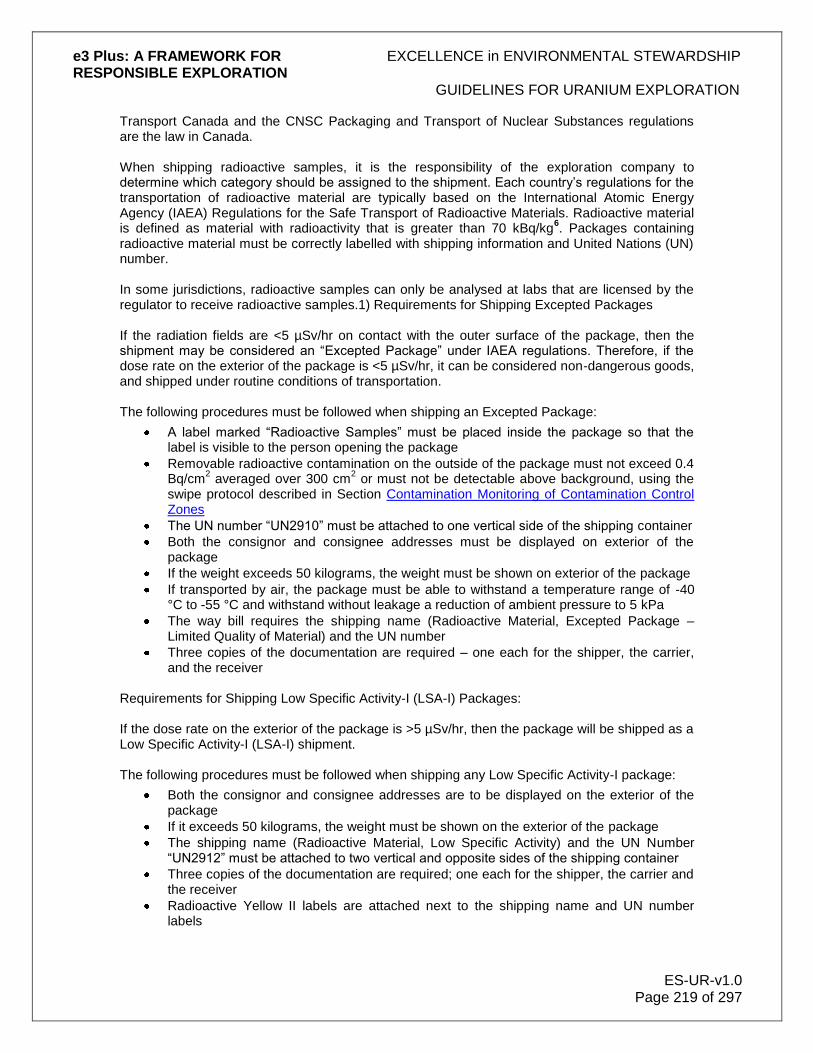
e3 Plus: A FRAMEWORK FOR EXCELLENCE in ENVIRONMENTAL STEWARDSHIP RESPONSIBLE EXPLORATION
GUIDELINES FOR URANIUM EXPLORATION
ES-UR-v1.0 Page 219 of 297
Transport Canada and the CNSC Packaging and Transport of Nuclear Substances regulations are the law in Canada. When shipping radioactive samples, it is the responsibility of the exploration company to determine which category should be assigned to the shipment. Each country‟s regulations for the transportation of radioactive material are typically based on the International Atomic Energy Agency (IAEA) Regulations for the Safe Transport of Radioactive Materials. Radioactive material is defined as material with radioactivity that is greater than 70 kBq/kg
6. Packages containing
radioactive material must be correctly labelled with shipping information and United Nations (UN) number. In some jurisdictions, radioactive samples can only be analysed at labs that are licensed by the regulator to receive radioactive samples.1) Requirements for Shipping Excepted Packages If the radiation fields are <5 µSv/hr on contact with the outer surface of the package, then the shipment may be considered an “Excepted Package” under IAEA regulations. Therefore, if the dose rate on the exterior of the package is <5 µSv/hr, it can be considered non-dangerous goods, and shipped under routine conditions of transportation. The following procedures must be followed when shipping an Excepted Package:
A label marked “Radioactive Samples” must be placed inside the package so that the label is visible to the person opening the package
Removable radioactive contamination on the outside of the package must not exceed 0.4 Bq/cm
2 averaged over 300 cm
2 or must not be detectable above background, using the
swipe protocol described in Section Contamination Monitoring of Contamination Control Zones
The UN number “UN2910” must be attached to one vertical side of the shipping container
Both the consignor and consignee addresses must be displayed on exterior of the package
If the weight exceeds 50 kilograms, the weight must be shown on exterior of the package
If transported by air, the package must be able to withstand a temperature range of -40 °C to -55 °C and withstand without leakage a reduction of ambient pressure to 5 kPa
The way bill requires the shipping name (Radioactive Material, Excepted Package – Limited Quality of Material) and the UN number
Three copies of the documentation are required – one each for the shipper, the carrier, and the receiver
Requirements for Shipping Low Specific Activity-I (LSA-I) Packages: If the dose rate on the exterior of the package is >5 µSv/hr, then the package will be shipped as a Low Specific Activity-I (LSA-I) shipment. The following procedures must be followed when shipping any Low Specific Activity-I package:
Both the consignor and consignee addresses are to be displayed on the exterior of the package
If it exceeds 50 kilograms, the weight must be shown on the exterior of the package
The shipping name (Radioactive Material, Low Specific Activity) and the UN Number “UN2912” must be attached to two vertical and opposite sides of the shipping container
Three copies of the documentation are required; one each for the shipper, the carrier and the receiver
Radioactive Yellow II labels are attached next to the shipping name and UN number labels

e3 Plus: A FRAMEWORK FOR EXCELLENCE in ENVIRONMENTAL STEWARDSHIP RESPONSIBLE EXPLORATION
GUIDELINES FOR URANIUM EXPLORATION
ES-UR-v1.0 Page 220 of 297
On the Radioactive Yellow II labels the following must be written:
“LSA-I” in Radioactive Contents section
The activity level in the package, estimated in Bq
The Transport Index. This index is the gamma radiation field in mSv/hr at a distance of 1 m from the exterior of the package multiplied by 100 – or the field in μSv/hr/10. For example, the Transport Index for 4.5 µSv/hr will be 0.5.
The package for an LSA-I Shipment must satisfy the IAEA Requirements for Type 1 Industrial Packages (Type IP-1), which are the same as for an Excepted Package, plus:
The smallest external dimension of the package cannot be less than 10 cm
The container must be durable and legally marked on the outside “Type IP-1” 6
For uranium ore, a pail of core pieces would have a radiation field >5 µSv/hr at 1 m distance/height from the surface of the pail.
13.8.3 Packaging Samples for Shipment Protocol
All personnel handling radioactive material shall:
Be properly trained in the handling and shipping of radioactive material.
Follow same RP procedures as core facility personnel
Store and package samples for shipment at a designated site (core facility)
Move packaged material to a low background level area, and take gamma measurements – on contact and at 1m – on as many sides of the package as possible
Record the maximum contact and 1 m reading in μSv/hr
Take gamma measurements for each package, if there is more than one package (e.g., pail, drum)
Move away from the samples when filling out shipment forms
Fill in the proper forms and labels based on the gamma measurements
13.8.4 Transportation of Samples
Soil, rock, and silt samples will be placed in plastic bags before shipping from the exploration site
For shipment to the lab:
Packages will be packed so as not to exceed the limits for a Low Specific Activity-I (LSA-I) packages
Samples will be packaged so as not to exceed 5 µSv/hr, whenever possible
Proper containers (i.e., IP3 type – metal) will be used
Samples will be shipped by the appropriate transportation means to the lab
13.8.5 Emergency Measures
Emergency response measures need to be in place in case an accident or spill occurs. These measures can be in form of a stand-alone emergency response plan (e.g., a manual) or may be in the form of a contract with commercial emergency response service providers. Personnel undertaking shipping of radioactive materials need to be trained in emergency procedures.

e3 Plus: A FRAMEWORK FOR EXCELLENCE in ENVIRONMENTAL STEWARDSHIP RESPONSIBLE EXPLORATION
GUIDELINES FOR URANIUM EXPLORATION
ES-UR-v1.0 Page 221 of 297
As a first response the following actions are recommended:
If an accident or spill occurs, cover the material with plastic sheeting and secure it
Contain the spill to prevent the potential contamination of wider areas or nearby water sources
Minimize the time spent in close proximity to the material, as well as potential ingestion or inhalation of the material
Contact health and safety services immediately, depending on the size and nature of the spill/accident
After responding, ensure that any contaminated clothing and equipment is properly cleaned up
13.9 Glossary of Acronyms
ALARA As low as reasonably achievable (social and economic factors taken into account)
ALI Annual limit of intake
Bq Becquerel – unit of radioactive material, one distintegration per second
CNSC Canadian Nuclear Safety Commission
cpm Counts per minute
cps Counts per second
DRD Direct reading dosimeter
EHS Environment, Health, and Safety
EPD Electronic personal detector
IAEA International Atomic Energy Agency
LLRD Long-lived radioactive dust
LSA Low specific activity
NEW Nuclear energy worker
NORM Normally occurring radioactive materials
PAD Personal alpha dosimeter
PPE Personal protective equipment
R Roentgen – unit of measurement for ionizing radiation; 1 R/hr = approximately 10,000 µSv/hr (see µSv below)
RAB Rotary air blast (drilling)
RnP Radon progeny
RP Radiation protection
RPP Radiation Protection Program
RSO Radiation Safety Officer
Sv Sievert – unit of measurement for radiation dose; 1Sv = 1 million microsieverts (µSv)
TDG Transportation of Dangerous Goods (regulations)
TLD Thermoluminescent detector
UN United Nations
µSv Microsieverts; 1 million µSv = 1 Sv (see Sv above)
WL/WLM Working level/Working level months
e3 Plus: A FRAMEWORK FOR EXCELLENCE in ENVIRONMENTAL STEWARDSHIP RESPONSIBLE EXPLORATION
GUIDELINES FOR URANIUM EXPLORATION
ES-UR-v1.0 Page 222 of 297
13.10 References and Links*
Canadian Government Canadian Council of Ministers of the Environment – Canadian Water Quality Guidelines, www.ccme.ca/publications/can_guidelines.html Canada‟s Nuclear Safety and Control Act – Radiation Protection Regulations, http://laws.justice.gc.ca/en/n-28.3/sor-2000-203/154458.html Canadian Nuclear Safety Commission (CNSC), www.nuclearsafety.gc.ca/eng/index.cfm Canadian Nuclear Safety Commission (CNSC) – Packaging and Transport of Nuclear Substances, http://laws.justice.gc.ca/en/n-28.3/sor-2000-208/154290.html Health Canada – Canadian Guidelines for the Management of Naturally Occurring Radioactive Materials (NORM), http://www.hc-sc.gc.ca/ewh-semt/pubs/contaminants/norm-mrn/concern-probleme-eng.php Health Canada – Environmental & Workplace Health, National Dose Registry, National Dose Registry Health Canada – Occupational Exposure to Radiation, It's Your Health - Occupational Exposure to Radiation Transport Canada – Transportation of Dangerous Goods, http://www.tc.gc.ca/tdg/ Canadian Provincial Governments Newfoundland and Labrador – Environmental Guidelines for Construction and Mineral Exploration Companies, www.gov.nl.ca/mines&en/mqrights/environment.pdf Newfoundland and Labrador – Mines and Energy Legislation, www.gov.nl.ca/mines&en/legislation/#mines Saskatchewan – The Radiation Health and Safety Regulations 2005, http://www.qp.gov.sk.ca/documents/English/Regulations/Regulations/R1-1r2.pdf Environment – Mineral Exploration Guidelines for Saskatchewan, http://www.publications.gov.sk.ca/details.cfm?p=10611 Saskatchewan Labour – Radiation Protection Guidelines for Uranium Exploration, http://www.labour.gov.sk.ca/Default.aspx?DN=25dcdf65-129a-4928-9f72-9431733643da Worksafe Saskatchewan – Radiation, http://www.worksafesask.ca/topics/specific_hazards/physical/radiation.html Other American Nuclear Society, Michigan Section – Radiation Protection Training, http://local.ans.org/mi/Teacher_CD/Teacher%20Guides/RADGRADcourse.ppt Queensland Government, Department of Minerals and Energy – Technical Guidelines for the Environmental Management of Exploration and Mining in Queensland,

e3 Plus: A FRAMEWORK FOR EXCELLENCE in ENVIRONMENTAL STEWARDSHIP RESPONSIBLE EXPLORATION
GUIDELINES FOR URANIUM EXPLORATION
ES-UR-v1.0 Page 223 of 297
http://www.epa.qld.gov.au/ecoaccess/mining/Technical_Guidelines Queensland Government, Department of Mines and Energy – Guidance note QGN12: Radiation protection from naturally occurring radioactive materials (NORM) during exploration, http://www.minerals.org.au/__data/assets/pdf_file/0008/26882/guidance_notes12.pdf International Atomic Energy Agency (IAEA) – Safety Standards, Regulations for the Safe Transport of Radioactive Material, 2005 Edition, Safety Requirements, http://www-pub.iaea.org/MTCD/publications/PDF/Pub1225_web.pdf International Atomic Energy Agency (IAEA) – Transport of radioactive material, Published Safety Standards, http://www-ns.iaea.org/standards/documents/default.asp Radiation Measurement Units – International (SI) System, Radiation Units Conversion Table * PDAC welcomes contributions of other website resources of interest.

e3 Plus: A FRAMEWORK FOR EXCELLENCE in ENVIRONMENTAL STEWARDSHIP RESPONSIBLE EXPLORATION
RECLAMATION AND CLOSURE
ES-RC-v1.0 Page 224 of 297
14.0 Reclamation and Closure
The role of reclamation and closure in any mineral exploration project can be regarded as the final chapter in the life of that project. When the exploration project develops further into a feasibility study or a full-scale mining operation, however, then the reclamation process undertaken at the exploration stage becomes the first step in the final rehabilitation of the mine. There are many definitions used in describing reclamation and closure. These include:
Decommissioning. This is the transitional period between the cessation of operations and the final closure of that operation.
Reclamation. This refers to the physical aspects of earth moving, regrading and revegetation.
Rehabilitation. Another word for reclamation, this term is used extensively in countries other than North America.
Closure. This is a term reserved for the point in time when revegetation has been completed, waste materials have been removed to the extent practical, a final surface and ground water monitoring program has been initiated, and the maximum degree of passive management has been implemented.
14.1 Principles of Reclamation
Reclamation is the process whereby the impact created by exploration upon the environment is minimized, and where the environmental disturbance to an area is remediated to the point where the land:
Is safe and stable
Is restored as near as possible to its pre-disturbance condition
Has its environmental values safeguarded
Has an appropriate sustainable ecosystem
An integral part of an exploration program is to plan operational objectives in advance of any activity taking place. Operational objectives should also include a well-defined reclamation objective that is properly planned, in order to meet the criteria for success.
Include in the plan an appropriate final land use:
Agreed to by the stakeholders
Defined in consultation with relevant interest groups
To maintain or monitor that land use into the future, the plan needs to define the required:
Financial commitment
Level of management Reclamation normally consists of a number of definitive steps that need to be implemented at appropriate times and at the appropriate level. These steps can be categorized into 4 major stages:
1. Baseline environmental studies and information gathering
2. Landform design and the reconstruction of a stable land surface

e3 Plus: A FRAMEWORK FOR EXCELLENCE in ENVIRONMENTAL STEWARDSHIP RESPONSIBLE EXPLORATION
RECLAMATION AND CLOSURE
ES-RC-v1.0 Page 225 of 297
3. Revegetation or the development of an alternative land use on the reconstructed landform
4. Environmental audit to monitor the success of the rehabilitation process These stages normally can be applied to most activities likely to be encountered during an exploration program.
Proper project closure is therefore the result of a combination of well-planned objectives, long-term commitments, and multi-party cooperation. Public education, in addition to participation, is a major factor because in the absence of knowledge, apprehension resides.
14.1.1 Objectives of Reclamation
The objective of rehabilitating a typical exploration site is to minimize long-term environmental liability by:
Attaining regulatory compliance
Maintaining geotechnical stability
Restoring native ecosystems
Reclaiming to a pre-existing land use
Striving to achieve a more beneficial land use
Reducing the social impact on local communities Successful rehabilitation must be sustainable in the longer term, and requires an understanding of the basic concepts of soil conservation, slope management, plant succession and biodiversity. In addition, use professional practice project management concepts to ensure the program‟s complete success. Project closure is a "whole of project life" process involving:
Stakeholder Engagement. The identification of stakeholders and interested parties is an important part of the process.
Planning. Closure planning is required to ensure that closure is technically, economically, and socially feasible.
Provision of Funding. A cost estimate for closure should be developed from the closure plan.
Implementation. The implementation of the closure plan should reflect the different stages of the operation.
Standards and Completion Criteria. Completion criteria are specific to the project being closed, and should consider its unique set of environmental, social, and economic circumstances.
Mining Title Relinquishment. A responsible authority should be identified and held accountable to make the final decision on accepting closure.
14.1.2 Commitment to Reclamation
A commitment to reclamation is often required as an integral part of both project planning and statutory permitting. To fulfill that commitment, be prepared to assign resources to the reclamation program. This commitment must be fully realized at both the management and operational levels of the exploration activity, in order to minimize the long-term and the short-term environmental and economic liabilities.

e3 Plus: A FRAMEWORK FOR EXCELLENCE in ENVIRONMENTAL STEWARDSHIP RESPONSIBLE EXPLORATION
RECLAMATION AND CLOSURE
ES-RC-v1.0 Page 226 of 297
If the project extends beyond the exploration phase, deviation from the management program over time, inadequate baseline studies, and inadequate field monitoring will likely result in increased costs at closure. A commitment must be made, not only to the overall closure approach or concept if a mine develops, but also to the individual components of that development. This involves initiating ongoing monitoring programs early on during the exploration phases of the project. An environmental audit system offers the best approach toward maintaining a commitment to closure. Many companies have some form of audit program in place that involves both internal and external technical and legal experts. It is important for an audit program to commit to:
Ongoing revegetation studies
Ongoing surface water quality studies
Ongoing ground water quality studies
Ongoing refuse disposal
Ongoing erosion control
Maintenance of topsoil stockpiles
Maintenance of backfill material
Monitoring of effects upon flora and fauna
Monitoring of any social disruption to local inhabitants Also, it is important to make a commitment to the continued evaluation of reclamation alternatives, as well as to the continued education of environmental personnel and the public, regarding the potentially changing reclamation requirements. If companies, and the industry as a whole, do not commit to the conceptual and cash requirements of closure and reclamation, then some other entity is likely to do so, either through litigation or legislation.
Figure27: With proper capping and, if necessary cementing, seepage of groundwater with high metal content can be avoided. © Noranda/Falconbridge.

e3 Plus: A FRAMEWORK FOR EXCELLENCE in ENVIRONMENTAL STEWARDSHIP RESPONSIBLE EXPLORATION
RECLAMATION AND CLOSURE
ES-RC-v1.0 Page 227 of 297
14.1.3 Cooperation in Reclamation
Make every effort to establish both internal and external cooperation and understanding between the participating stakeholders in the reclamation process. It is also the company‟s responsibility to ensure complete cooperation between operational people and corporate personnel in the office, so that everyone has a proper understanding of all the environmental concerns. It is also a good idea to promote complete cooperation and understanding between the technical and non-technical staff within the individual operation. The company is responsible for making sure that there is always cooperation and information exchange among:
The exploration operation
The community
The regulatory agencies
Without this cooperation and information exchange, the reclamation process may become very time-consuming due to:
Mistrust
Inflexibility
The misinterpretation of concepts and actions The objectives must always be clearly set out for all stakeholders. From a cooperation, coordination, and communication standpoint, the global exploration community must share their ideas and their reclamation plans, and recognize that good ideas may come from elsewhere. In this era of instantaneous electronic communications, there is no excuse for any lack of information exchange. It is important to recognize that the future success of mining will not be tied to the promises made during permitting, or to the actual environmental, health, and safety record compiled during any operations. It will be tied to the condition of the project site after closure. Consistent cooperation, coordination, and communication result in good exploration and serve to minimize future problems.
14.2 Planning and Timing
Develop a conceptual reclamation plan which can be reviewed on a periodic basis, as the project progresses from the early exploration stage into advanced exploration, feasibility and even beyond. If there is no well-defined and dynamic reclamation plan, an environmental assessment or an environmental impact study may be imposed as a legal requirement, prior to the abandonment of the project. It is necessary, therefore, to develop and periodically review the reclamation plan and to be aware that this approach has become a standard or required practice in many parts of the world. The following factors are important when considering reclamation plan options:
Public safety hazards and risks
Ecological compatibility
Potential area of substantial disturbance

e3 Plus: A FRAMEWORK FOR EXCELLENCE in ENVIRONMENTAL STEWARDSHIP RESPONSIBLE EXPLORATION
RECLAMATION AND CLOSURE
ES-RC-v1.0 Page 228 of 297
Community expectations
Future land use and resource demands
Aesthetics
Planning and timing
14.2.1 Reclamation Plan
Prior to the commencement of any exploration work, hold a planning session to consider the environmental aspects of the project, and:
Identify those sensitive environmental features that may require some form of protection, prior to the start of the project
Consult with appropriate stakeholders, such as local inhabitants, aboriginal or native groups, hunters and trappers organizations, and local regulatory authorities (e.g., Departments of Fisheries and Oceans, Wildlife, Natural Resources)
Identify what baseline environmental studies are required for the level of work to be undertaken (e.g., burial or sacred sites, harvesting needs, wildlife and floral habitat, water testing)
Where baseline studies are required, prior to any substantial disturbance of the surroundings, consider sampling the:
Water
Soil
Air
Vegetation
Wildlife habitats
Also:
Ensure that workers are familiar with environmental obligations, are aware of applicable regulatory requirements and are properly trained to carry out any remedial procedures pertaining to environmentally related situations if they occur (e.g., fuel spills)
Ensure that the exploration program is designed and budgeted to take into account all potential sensitivities associated with native lands, archaeological sites, and other land users
Also be aware of the special care and planning required for exploration activities undertaken in or close to certain habitats, such as:
Dunes
Coasts
Permafrost areas
Marshes
Bogs
Lakes
Streams
Rivers
Deserts

e3 Plus: A FRAMEWORK FOR EXCELLENCE in ENVIRONMENTAL STEWARDSHIP RESPONSIBLE EXPLORATION
RECLAMATION AND CLOSURE
ES-RC-v1.0 Page 229 of 297
Have a plan for all stages of the program, detailing how it is to proceed from the planning stage, through the first reconnaissance, follow-up, advanced exploration (including evaluation), and finally to closure. In this plan:
Include details of how all sites are to be disturbed and then restored, and how runoff and erosion are to be controlled, where applicable.
Ensure that contractors utilized for such activities as drilling, excavation, geophysical surveys, and helicopter use, etc. are familiar with, and comply with, environment policy and the plans for reclamation at the closure of the project. It is important to ensure that they minimize their environmental disturbance, in order that the reclamation program can be carried out successfully.
14.2.2 Timing
Timeframes for reclamation can be quite variable, as they depend upon the regulatory requirements that exist in a particular state or country. Initiate an educational program for the public and for the exploration personnel as the project closure period approaches, in order to satisfactorily address the reclamation concerns of all interested parties. Many exploration programs are multi-year, and may involve different activities each year. In the educational program, focus on the current year's plans; leave the more distant future plans, which are dependent upon results, in an outline form. If the project proceeds to the feasibility stage or beyond, it would then likely require a more formal and separate plan. This would include a site-specific Environmental Management System (EMS) and Environmental Management Plan (EMP), incorporating all the legal requirements for project reclamation and closure. Conduct monitoring programs to gather the information necessary to make longer-term predictions of impact, particularly as monitoring requirements may change over time (e.g., analytical detection limits are lowered, new legislation is enacted). Initiate these programs as early as possible at the commencement of the project, and continue them throughout the life of the project.
14.3 Site Preparation
Prior to the commencement of any exploration activity, assess the impact that this activity will have upon the environment. Impacts that change conditions that will affect project objectives are also the environmental impacts that will affect the reclamation plan and any site preparations that are required. The impact assessment will allow the program to minimize environmental disturbance, and ensure that proper closure can be achieved at the end of the project. Factors to consider in the assessment include:
Physical stability. Engineer buildings, structures, slopes, underground openings, etc., so as not to pose a hazard to the public health and safety, and to stop any material eroding from the land to waterways at concentrations that are harmful.
Chemical stability. Stabilize minerals, metals and other contaminants. They and their weathering, oxidation, or leaching products must not transport contaminants in excessive concentrations into the environment.
Land use. The abandoned site should be able to be reclaimed to its pre-activity condition, to conditions that are compatible with the surrounding lands, or to an alternative
e3 Plus: A FRAMEWORK FOR EXCELLENCE in ENVIRONMENTAL STEWARDSHIP RESPONSIBLE EXPLORATION
RECLAMATION AND CLOSURE
ES-RC-v1.0 Page 230 of 297
productive land use agreed to by other stakeholders. Generally this will require the land to be aesthetically similar to its surroundings and to be capable of supporting a self-sustaining ecosystem typical of the area.
Sustainable development. Maintain elements of the site development that contribute to the sustainability of social and economic benefits, and transfer them to succeeding custodians.
The assessment of these types of impacts and closure factors must address the specific site requirements for the exploration activity being undertaken, and the particular climatic region involved. It is important to anticipate, as early in the process as possible, the potential future impacts, risks and liabilities so as to plan for their elimination or minimization.
14.4 Landforms, Stability, and Land Use
A major factor to consider during exploration site reclamation planning is to anticipate the shape of the final landform and identify those factors that will impact on that final landform. Develop a clear understanding of the desired post-activity land uses expected by the various stakeholders, before planning for acceptable rehabilitated landforms. The final landform will also affect the types of revegetation processes and species to use to ensure long-term stability and erosion control. Consequently, the most appropriate option for land reshaping will vary from project to project, depending on a range of factors including:
Legal requirements
Climate
Topography
Soils
Community views Each of these is discussed in more detail in the following subsections. Landform and land use are closely interrelated. The philosophy of returning land as closely as possible to its original landform and use applies to the industry throughout the world, and with good reason. There are many factors - such as community expectations, compatibility with local land use practices and regional infrastructure, or the need to replace natural ecosystems and faunal habitats - which all support returning the land as closely as possible to its original appearance and productive capacity. In most cases, however, it is up to the company to decide the final landform and land use.
14.4.1 Legal Requirements
The conditions attached to approvals, exploration leases, and various subsidiary licenses and permits may specify certain limitations. These can include maximum slope angles, the provision for surface drainage, the salvage and use of topsoil, and the choice of vegetation species to use in reclamation. These conditions will set minimum parameters for landform design. The conditions imposed by government planning instruments, such as state, regional and local environmental plans, and council zoning, may limit the range of land uses available after rehabilitation; it is necessary that everyone is aware of these. In particular, planning instruments may restrict the visual impact of disturbed land, and may require the preservation of items of cultural and heritage value, and dictate the vegetation species that can be used for rehabilitation.

e3 Plus: A FRAMEWORK FOR EXCELLENCE in ENVIRONMENTAL STEWARDSHIP RESPONSIBLE EXPLORATION
RECLAMATION AND CLOSURE
ES-RC-v1.0 Page 231 of 297
14.4.2 Climate
The annual rainfall, its type and distribution, has perhaps the greatest influence on the design of stable landforms and drainage systems. Take careful account of the local conditions in planning reclamation. Together with the temperature regime, rainfall determines the type of vegetation that can be grown successfully. Monsoon weather systems, dominated by high intensity storms, will require that special attention be paid to drainage and to the early stabilization of exposed slopes. Winter or summer dominance of the rainfall has an obvious effect on the type of vegetation grown and the timing of revegetation. The reliability of rainfall probably has the strongest climatic influence on vegetation and landform.
14.4.3 Topography
The most important components of topography are:
Slope gradient
Elevation
Drainage density (the total length of natural watercourses per unit area)
Aspect, or the direction in which slopes face, also has a pronounced effect on localized temperature and moisture regimes, both of which can influence vegetation growth. While little can be done to alter slope aspects, it is important to be aware of the subtle changes that these may dictate in land use, species selection for revegetation, or the management for various parts of each site. The angle and length of natural slopes within and surrounding the exploration site will influence the amount of reshaping necessary to achieve visual blending of the site. Slope angle, and the degree to which the land is dissected by drainage channels, will affect its suitability for alternate uses. For example:
Slopes above 8° (14%) are generally unsuited to regular cropping, due to high erosion hazard
Slopes over 20° (36%) should not be subject to intense agriculture or grazing, and are more suited to revegetation with native species and a low-intensity land use
Drainage density is an important attribute in achieving long-term stability. The natural drainage pattern has evolved over geological time and is in equilibrium with the environment. The reclamation plan should take account of the drainage density prior to any disturbance, as this will provide a useful benchmark for the design of new landforms. However, changes to elevation, slope angles and slope lengths brought about by exploration activities such as excavation, dumping, and reshaping may render the new land surface susceptible to erosion. This may necessitate incorporating changes from the original drainage density in order to achieve long-term stability.
14.4.4 Soils
The distribution and quality of soil types over any area that will be disturbed by the exploration program, will influence the volume of topsoil and suitable subsoil available for topdressing. Past land uses, the extent of historic erosional damage, salination, and the presence of weeds and
e3 Plus: A FRAMEWORK FOR EXCELLENCE in ENVIRONMENTAL STEWARDSHIP RESPONSIBLE EXPLORATION
RECLAMATION AND CLOSURE
ES-RC-v1.0 Page 232 of 297
other undesirable species will affect the rehabilitation value of the soil. This in turn will affect the choice of landform and its use in rehabilitating disturbed areas.
14.4.5 Community Views
It is important to take into account the views and expectations of the community, and especially of the people in the local area, when deciding landforms and uses. Pay particular attention to people with a special interest (e.g., those whose land may be affected by the exploration activity), and community groups (e.g., local wildlife, botanical and historical societies, Aboriginal communities), which may have strong preferences about the landforms and future uses of the site. The local expertise of these people can be valuable for such things as advice on flood and drainage control, the collection of native species seed, as well as weed and feral animal control. Seek out community views on landform and land use in the consultation program during the early phases of project planning and design.
14.5 Soil Conservation
Most plants get their nutrients and water from the soil. Plants in turn are the main source of food for animals and birds. As a general rule, therefore, it is important to preserve soil – in particular topsoil – for reclamation use wherever possible, as it can be a valuable source of seed, nutrients, and microorganisms. The physical properties of topsoil can also be an advantage in providing a suitable microenvironment for seed germination, and in mitigating the problems of clay dispersion and surface crusting. When stockpiling topsoil:
Plan to respread or reuse the topsoil as soon as possible, to maintain seed viability, nutrient quality, and mycorrhizal (symbiotic) fungi activity.
Store topsoil in low mounds of 1-2 m maximum height; do not store it in large heaps. (Good practice for topsoil storage height from various sources ranges between 0.6 m-3 m. The 1 m-2 m height has been suggested here as a reasonable midpoint within this range.)
Locate the stockpiles where they will not be disturbed.
Revegetate stockpiles to protect from erosion, discourage weeds, and maintain active populations of beneficial soil microbes.
Consider by what method soil will be respread.
Make an assessment of the relative advantages of topsoil, compared to the material to be covered, in terms of its physical and chemical properties. Where topsoil is in short supply, give preference first to topdressing those areas most susceptible to soil erosion. These critical areas include newly formed watercourses, and areas where dense, high-quality vegetation is required. Consider separately stripping topsoil and subsoil, and replacing them in their proper sequence for areas of arable land where subsequent productivity is important. It is paramount that soil be conserved to provide the ecological balance required to successfully rehabilitate the project area. The following subsections set out guidelines to consider in soil handling and treatment.

e3 Plus: A FRAMEWORK FOR EXCELLENCE in ENVIRONMENTAL STEWARDSHIP RESPONSIBLE EXPLORATION
RECLAMATION AND CLOSURE
ES-RC-v1.0 Page 233 of 297
14.5.1 Soil Handling
Topsoil is often the most important factor in successful rehabilitation, particularly where the objective is to restore a native ecosystem. The term “topsoil” generally refers to the A1 horizon of the soil, which is usually darker than the underlying soil because of the accumulation within it of organic matter. The topsoil contains the majority of the seeds, other plant propagules (e.g., rhizomes, lignotubers, and roots), soil microorganisms, organic matter, and much of the more labile (more readily cycled) plant nutrients. Some guidelines to help ensure successful topsoil handling include the following:
Consider the thickness of both useful and unfavourable soil materials
Check rooting depths in undisturbed soils, as they can be a useful guide to determining the thickness of soil materials worth salvaging
Remove the complete A1 horizon
Recover the top 100-300 mm of soil, when the A1 horizon is not obvious
Do not include deeper soil layers with adverse chemical and physical properties (e.g., B horizons with a higher clay content, cemented horizons, subsoils with high concentrations of salts or carbonates)
Use the subsoil as a substrate for rehabilitation, if the topsoil contains large numbers of seeds of undesirable species
Ensure that contractors are informed of the rehabilitation program. Pre-work site visits are valuable, to acquaint the equipment supervisor and operators with the identification of the soil layers that will need to be handled, especially the depth to unfavourable subsoil. Develop a consistent method for locating separate piles of topsoil and less desirable fill materials. On level or gently sloping ground, for example, topsoil and excavated subsoil can simply be placed in the most convenient locations for respreading. Other guidelines to follow include:
Use excavators for excavations because of their greater flexibility in removing and placing soil materials. Front-mounted blade equipment is particularly unsuitable for construction on slopes because of its uncontrolled sidecasting.
Minimize the inclusion of stumps and woody debris with topsoil.
Ensure that topsoil piles are protected from wind and water erosion, and are not buried.
Avoid the handling of topsoil during wet conditions. Make sure that all excavations are backfilled in the reverse order of their excavation, which is subsoil first followed by topsoil. Scatter vegetation debris on the soil surface to provide some protection from erosion until vegetation is established. When spreading stockpiled topsoil:
Avoid creating either a smooth-graded or coarse, cloddy surface
Ensure that the roughness of the final surface is suitable for the subsequent seeding and fertilization treatments
Where rehabilitation treatments will include both tillage and topsoil:
Plan the sequence of operations to avoid recompacting tilled areas
Use winged subsoilers to till under respread topsoil with a minimum of mixing

e3 Plus: A FRAMEWORK FOR EXCELLENCE in ENVIRONMENTAL STEWARDSHIP RESPONSIBLE EXPLORATION
RECLAMATION AND CLOSURE
ES-RC-v1.0 Page 234 of 297
Utilize excavators to respread topsoil and decompact in one operation, by tilling a strip just ahead of a windrow of recovered topsoil, which is then progressively spread across the tilled surface
In some cases, topsoil stockpiling may be impractical. For example, on very rocky sites it may be too difficult to separate and stockpile topsoil. A high rainfall area where the site is continuously saturated is also unsuitable for topsoil respreading.
14.5.2 Tillage
Tillage is a technique to use primarily to decompact the soil and to re-establish soil porosity, thereby allowing plant roots to penetrate deeper into the soil. It is generally accepted that increasing the rooting depth (usually to around 50 cm) is considered advantageous for plants, even though the natural vegetation may have originally grown on shallower soils. Deep tillage has the added benefit of breaking up any impermeable layers and perhaps mitigating some of the adverse effects of the initial disturbance on the surface soils. Equipment used for tillage can vary greatly, depending upon the site requirements. Examples of tillage equipment are given in the following subsections.
14.5.2.1 Winged Subsoilers
Winged subsoilers are effective and efficient tools for decompacting soils in rehabilitation work, if used by an experienced operator under suitable soil conditions. The winged subsoiler, with the wings set at the proper angle, lifts the soil and then allows it to fall back and shatter in place as the implement passes. A good subsoiling operation can leave existing vegetation sufficiently intact so it continues to grow. On the better models of winged subsoilers, the wings can be adjusted to match soil conditions, particularly if the soil is dry, high in clay content, or is extremely dense. The shank spacing also can usually be adjusted, to accommodate different site sizes or road widths. Even though the wings are independently mounted to prevent hang-ups, a subsoiler is often ineffective on sites containing large rocks (>50%) or buried logs. The winged subsoiler is the most effective implement for decompacting uniformly large areas that have similar soil conditions.
14.5.2.2 Excavators
There are many situations where hydraulic excavators are more flexible tools than winged subsoilers. Excavators are more readily available, and a number of attachments are available to achieve different soil reclamation objectives, including mixing, mounding, tilling, and spreading mulches. A conventional bucket is suitable for a limited amount of tillage where soil with the correct moisture content can be lifted and dropped to achieve good shatter. Various other attachments are also available including:
Mounders
Mulchers
Rototillers
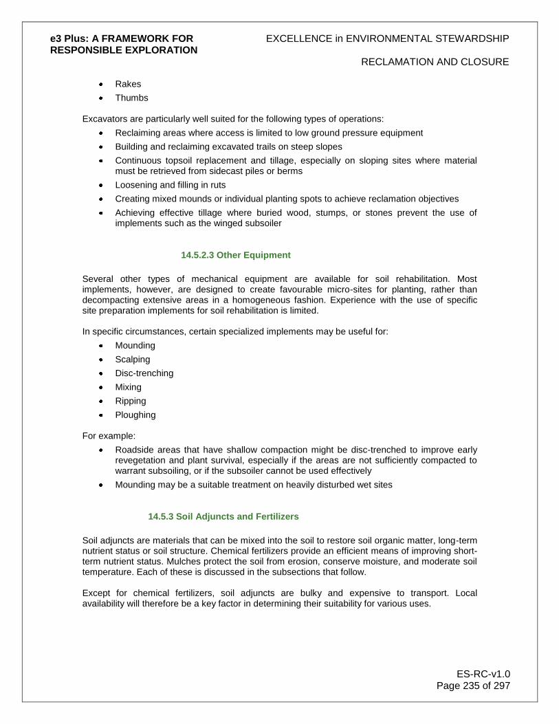
e3 Plus: A FRAMEWORK FOR EXCELLENCE in ENVIRONMENTAL STEWARDSHIP RESPONSIBLE EXPLORATION
RECLAMATION AND CLOSURE
ES-RC-v1.0 Page 235 of 297
Rakes
Thumbs
Excavators are particularly well suited for the following types of operations:
Reclaiming areas where access is limited to low ground pressure equipment
Building and reclaiming excavated trails on steep slopes
Continuous topsoil replacement and tillage, especially on sloping sites where material must be retrieved from sidecast piles or berms
Loosening and filling in ruts
Creating mixed mounds or individual planting spots to achieve reclamation objectives
Achieving effective tillage where buried wood, stumps, or stones prevent the use of implements such as the winged subsoiler
14.5.2.3 Other Equipment
Several other types of mechanical equipment are available for soil rehabilitation. Most implements, however, are designed to create favourable micro-sites for planting, rather than decompacting extensive areas in a homogeneous fashion. Experience with the use of specific site preparation implements for soil rehabilitation is limited. In specific circumstances, certain specialized implements may be useful for:
Mounding
Scalping
Disc-trenching
Mixing
Ripping
Ploughing For example:
Roadside areas that have shallow compaction might be disc-trenched to improve early revegetation and plant survival, especially if the areas are not sufficiently compacted to warrant subsoiling, or if the subsoiler cannot be used effectively
Mounding may be a suitable treatment on heavily disturbed wet sites
14.5.3 Soil Adjuncts and Fertilizers
Soil adjuncts are materials that can be mixed into the soil to restore soil organic matter, long-term nutrient status or soil structure. Chemical fertilizers provide an efficient means of improving short-term nutrient status. Mulches protect the soil from erosion, conserve moisture, and moderate soil temperature. Each of these is discussed in the subsections that follow. Except for chemical fertilizers, soil adjuncts are bulky and expensive to transport. Local availability will therefore be a key factor in determining their suitability for various uses.

e3 Plus: A FRAMEWORK FOR EXCELLENCE in ENVIRONMENTAL STEWARDSHIP RESPONSIBLE EXPLORATION
RECLAMATION AND CLOSURE
ES-RC-v1.0 Page 236 of 297
14.5.3.1 Organic Soil Adjuncts
Organic materials from a variety of sources can be used as soil adjuncts, including:
Topsoil salvaged from nearby construction sites
Residual vegetation
Manure
Hay
Straw
Sewage sludge
Municipal compost
Good reclamation projects take advantage of these materials as their availability arises. Consider the guidelines that follow in using these materials. Topsoil The most readily available organic material is usually the residual vegetation accumulated during the site construction. Large accumulations of material adjacent to roads and construction sites could be burned, depending upon local regulations and local customs in the project area, to provide ash that could serve as a soil amendment. Fine branches and foliage contain significant quantities of nutrients, and these can be mixed directly as a soil amendment to improve soil physical properties, enhance nutrient status, and to increase mineral soil organic matter content. Depending on the size and shape of the materials, it may be useful to chip fine residues where equipment is available. The material salvaged from other construction projects (e.g., permanent roads, landings) can also be used to supplement materials present on the site. Manure, Hay and Straw Little planning is needed to use these materials. Manure provides a good source of organic matter and includes nutrients such as nitrogen, phosphorus, and potassium. Hay from local meadows is a particularly good resource, as it is unlikely to introduce any unwanted species. Sometimes mouldy hay can be obtained very economically. Straw is usually free of weed seeds and has an intermediate C:N (carbon to nitrogen) ratio that is higher than hay, but lower than woody residues. (Note: The normal initial C:N ratio for a typical grass/leaf compost is 30:1, decreasing to about 10:1 as the composting process advances.) Sewage Sludge Sewage sludge has a high nutrient content, but is only available near population centres. Its high water content increases transportation costs, but specialized pumping and sprayer equipment allows for its application as slurry at some distance from roads. To protect ground and surface waters, consult with an expert to determine application rates, based on the nutrient and trace metal content of the sludge. Compost Municipal and other compost facilities may be available near populated areas. The nutrient concentration in composts is usually lower than those in sewage sludge, but nevertheless can be beneficial. Consider compost primarily as a source of organic matter, as opposed to a source of nutrients.

e3 Plus: A FRAMEWORK FOR EXCELLENCE in ENVIRONMENTAL STEWARDSHIP RESPONSIBLE EXPLORATION
RECLAMATION AND CLOSURE
ES-RC-v1.0 Page 237 of 297
14.5.3.2 Chemical Fertilizers
A single, large application of chemical fertilizer is usually insufficient to restore the nutrient capital of a degraded soil. If the soil organic matter has been displaced or destroyed, and if only limited vegetation cover is present, then most of the nutrients added in a large application may be lost from the site. Instead, use fertilization primarily to enhance the early establishment and growth of vegetation, which will restore soil structure and the content of organic matter.
Modest repeat applications may be needed until the internal nutrient cycle of the site is re-established and can meet the needs of the vegetation. However, do not consider a site adequately reclaimed if the survival of the vegetative cover depends solely upon its continued fertilization. Most vegetation species commonly respond to nitrogen fertilization, and sometimes to:
Phosphorus
Potassium
Sulphur
Any of these nutrients may be deficient in disturbed or reclaimed soils. Soil tests can be obtained from commercial laboratories to help determine fertilizer requirements for grasses and legumes. Fertilizer tends to be a small portion of total reclamation costs, so if nutrient deficiencies are anticipated, complete formulations are usually used at rates that approach safe maximums. Application rates for initial fertilization will usually range between 30 kg-100 kg N/ha, depending upon the:
Severity of nutrient depletion at the site
Risk of runoff
Amount and composition of seeded cover
Reclamation objectives
Consult with an expert in the area for more information on typical fertilizer application rates.
Set maximum fertilizer rates to reduce the risks of damaging vegetation from:
Over-fertilization
Losing fertilizer through runoff or leaching
The risk of fertilizer damage increases greatly with:
Decreasing moisture
Increasing temperature
Higher fertilization rates can therefore be used without damaging seedlings in climates with higher precipitation. However, in wet environments, large amounts of fertilizer can be lost from recently disturbed sites that are:
Low in organic matter
Have limited vegetation cover
Alternatives to consider when fertilizing are to:
Broadcast fertilizers on the surface

e3 Plus: A FRAMEWORK FOR EXCELLENCE in ENVIRONMENTAL STEWARDSHIP RESPONSIBLE EXPLORATION
RECLAMATION AND CLOSURE
ES-RC-v1.0 Page 238 of 297
Include fertilizers in a hydroseeding slurry
Incorporate fertilizers if shallow soil mixing (<20cm) is part of the reclamation plan Fertilizer can usually be applied at the time of seeding, ideally immediately after the seedbed is prepared. Higher losses of seed and fertilizer occur after the freshly prepared surface has been subjected to rainfall. Where vegetation is already established, apply fertilizer when growth is most rapid. There are 3 general formulations that can be considered for reclamation work:
1 Nitrogen alone may be suitable for light disturbance.
2 Nitrogen plus high P2O5 is used to enhance the establishment of grasses.
3 N=P2O5=K2O plus low sulphur will supply all the major nutrients that are likely to be deficient. This is an economical and effective choice. High analysis granular fertilizers are preferred because of their lower transport and handling costs. A complete fertilizer with approximately equal concentrations of the macronutrients (such as 19-18-18, containing 19% N, 18% P2O5 and 18% K2O) is desirable because of the low fertility of severely disturbed soils. Many possible formulations are available, and for most situations it is difficult to identify a clear advantage for any one recipe.
The best formulation to use will usually be dictated by:
Cost
Availability Other points to consider:
To avoid burning seed, do not mix seed and fertilizer together in the same bin for dry seed application
Where there is a risk of drought, reduce the single application rate or incorporate the fertilizer into the soil
If fertilizer supplies are limited, apply the fertilizer to critical locations, such as backfilled excavations and heavy use roads
A second fertilizer application within 3 to 5 years after seeding will help severely degraded soils, by maintaining the vigour of grasses and legumes at critical erosion control locations
Do not to apply slow-release fertilizers such as coated urea within 3 m of watercourses
14.5.3.3 Mulches
Mulches are non-living materials that can be spread over the soil surface to reduce erosion, and to aid plant establishment by conserving moisture and moderating soil temperatures. There are several types of mulches to select from, including relatively thick layers of organic material, manufactured mulch mats of various types, and thin layers of mulch primarily applied during hydroseeding. Each is discussed in more detail below. Thick mulches
Materials suitable for thick mulches include:
Residual vegetation (either fine-cut or chipped debris)
Straw
Hay
e3 Plus: A FRAMEWORK FOR EXCELLENCE in ENVIRONMENTAL STEWARDSHIP RESPONSIBLE EXPLORATION
RECLAMATION AND CLOSURE
ES-RC-v1.0 Page 239 of 297
As a rough guideline, 5-10 cm is a sufficient depth for most sites. Decomposition occurs slowly because the mulched layer dries out repeatedly, but the materials will eventually contribute to the restoration of soil organic matter. Thick mulches imitate the ecological functions of a vegetation cover. Primarily consider them for drought-prone sites, but they may also be appropriate where soils are:
Wet
Cold The mulch will keep fine-textured soils moist and soft, and plant roots may explore the interface between the mulch and mineral soil. Thick mulches will prevent the growth of:
Grass
Many weedy species These are best used in combination with planted shrubs and trees. Manufactured mulch mats
Various types of manufactured mulch mats are available, including plastic and fibre matting or netting materials. Some of these products can also aid in:
Seed germination
Vegetation establishment
For them to be effective, install mats in close contact with the soil surface. This may limit their suitability for the protection of roads where slopes often have rough surfaces. Their ability to trap sediment and biomass is useful in:
Building soil
Improving surface soil conditions
Restoring soil organic matter Due to cost, the use of manufactured mats is most often limited to small, critical areas, such as ditch linings or culverts. Thin mulches
Thin mulches are useful to aid the germination and establishment of grasses and legumes on drought-prone sites, highly erodible soils, unconsolidated (sandy) surface soils, and exposed slopes. Apply these mulches over the top of seed to protect it from desiccation and:
Wind
Water
Gravity movement
Some types of light mulches need a tackifier (binding agent) applied with them, to prevent them from blowing or washing away. The most common mulching technique for use in combination with grasses and legumes is ground wood fibres, mixed with a green dye to improve visibility. Apply it with a hydraulic seeder equipped with a mechanical agitator that can also combine in the seed and fertilizer.
e3 Plus: A FRAMEWORK FOR EXCELLENCE in ENVIRONMENTAL STEWARDSHIP RESPONSIBLE EXPLORATION
RECLAMATION AND CLOSURE
ES-RC-v1.0 Page 240 of 297
Thin straw mulches also offer excellent soil protection. These can be applied by:
Hand
Using a straw blower usually readily available through farm equipment suppliers The use of a blower will speed application and ensure more even mulch coverage. Recommended rates range from a minimum of 2,000 kg/ha to over 5,000 kg/ha. For maximum effectiveness, however, spray a tackifier over the surface straw to hold it in place. Mechanical means of anchoring straw are generally impractical for soil reclamation. These methods include:
Discing
Rolling
Covering with netting
14.6 Revegetation
Revegetation is a fundamental part of all rehabilitation projects, and the type of revegetation techniques to use depends largely upon the rehabilitation objectives. Rehabilitation objectives may include some or all of the following:
Controlling surface erosion
Increasing slope stability through the restoration of a root mat
Creating, restoring, or improving soil structure
Restoring biological properties affecting soil nutrient cycling
Reducing recompaction after tillage operations
Changing water relations on-site
Conserving or adding nutrients
Preventing the establishment of noxious weeds
Maintaining or achieving aesthetics
Producing a commercial forest or agricultural plot
Restoring and providing habitat or forage for wildlife If left unattended, bare soil will erode, recompact if already tilled, lose structure, lose nutrients, and undergo invasion by weed species. A wide variety of approaches to revegetation are available. Most traditional approaches have usually involved seeding a mixture of agronomic grasses and legumes to control erosion and establish vegetative cover. Many more modern rehabilitation projects, however, may have more demanding objectives, such as re-establishing a recommended land use for forestry, cattle grazing, wildlife refuge, or native flora conservation area. Sometimes techniques required for one objective, such as developing complete ground cover to prevent erosion, may conflict with other strategies, such as establishing a free-growing crop of trees. Some of the issues involved in the process of revegetation are discussed in the subsections that follow.

e3 Plus: A FRAMEWORK FOR EXCELLENCE in ENVIRONMENTAL STEWARDSHIP RESPONSIBLE EXPLORATION
RECLAMATION AND CLOSURE
ES-RC-v1.0 Page 241 of 297
Figure28: In many regions, drill sites can be reclaimed by revegetation with local plant species after ground preparation (scarifying). © Noranda/Falconbridge
14.6.1 Revegetation Strategies and Techniques
A revegetation strategy depends upon the reclamation objectives. Alternatives to consider, and different techniques which can be used, are included in the sections that follow, and in the information below:
To control surface erosion, use grass and legume seed mixes as the first choice, then shrub and hardwood species. Keep in mind, however, that grasses, particularly sod-forming species, may interfere with shrub and tree establishment on some sites.
Use vegetation with ecological characteristics that are compatible with the long-term objectives. Learn about the potential of native grasses and legumes, by experimenting on sites that have low erosion potential. Remember, however, that experience with native grasses and legumes may be limited in the area, and they may be in fact more risky than agronomic seed mixes, where immediate erosion control is required. Consult with a specialist in the area for help in selecting native plants for use in rehabilitation programs.
To restore and maintain soil structure, use grasses and legumes, especially in medium- and fine-textured soils.
Consider using native shrub and tree species, to enhance the development of a soil profile which best maintains the local ecological balance. These can also be successfully interplanted with exotic species such as conifers, wattles, or eucalypts, but they are less effective than grasses and legumes for short-term erosion control and for rapid improvement in soil structure.
Develop, or have an expert develop, site-specific requirements for seeding rates, planting densities, and species mixes. A more intensive approach to the reclamation work is often required than what is normally applied in agriculture.
Consider using bioengineering techniques in situations of high sensitivity or risk.
When developing strategies for revegetation, it is important to consider other uses of the site and their possible effects on the program. For example, where wildlife populations are large, plan to control browsing of the site by creating access barriers until the vegetation is sustainably developed, or by delaying planting until other food sources are available.
e3 Plus: A FRAMEWORK FOR EXCELLENCE in ENVIRONMENTAL STEWARDSHIP RESPONSIBLE EXPLORATION
RECLAMATION AND CLOSURE
ES-RC-v1.0 Page 242 of 297
Also, in areas where cattle are grazing, measures can be planned and implemented to prevent cattle from congregating on the reclaimed area, by minimizing use until tree seedlings are established, or by planting obstacles to protect seedlings. Local experience will often be the best source of innovative solutions to the problems associated with shared use of reclaimed areas by wildlife and cattle. Above all, remain flexible. There are an almost unlimited number of possible strategies available, so be guided by the ecological considerations of the site, the analysis of the risk, and the ultimate objectives.
14.6.2 Species Selection
The species selected for revegetation the project area will depend upon the:
Future land use
Soil conditions
Climate in the region
If the objective is to restore the native vegetation and fauna, then the species are already predetermined. If the soil conditions are substantially different after disturbance, then some exotic species may need to be introduced. Species considered to be appropriate to the reclaimed area have similar growth forms to the original vegetation and thrive in areas with comparable:
Soil types
Drainage status
Aspect
Climate A good practice is to search the area of the project locally for natural analogues to the area, and use them as models for site rehabilitation. Take care, however, to avoid introducing species that could become fire hazards, invade the surrounding areas of native vegetation, or become a weed for the local agricultural industry. Be aware that "pretty" reclamation may not be the most desirable or most acceptable. A former coal mine in northwestern North America is a good example. The operator began reclamation in the 1960's and by the 1980's was very proud of its picturesque effort. Unfortunately, the local Dall sheep were also impressed and hunters simply had to hang out near the site to bag a sheep without an arduous climb, as in past years, into the nearby mountain range. The sheep population suffered significantly and the operator was forced to alter its reclamation procedures to eliminate this unnatural animal attraction. Where the future land use is agriculture, then again the species selection for revegetation will be governed by what is generally used for pasture or crop in the area. Where a quick remedy is required for erosion control cover crops can be considered, but this must not be to the detriment of establishing an ecosystem based on returning the land to its previous balance. The following subsections contain information on specific plant groups that can be considered for revegetation. It is very important to always seek expert advice on species selection before implementing any reclamation program.

e3 Plus: A FRAMEWORK FOR EXCELLENCE in ENVIRONMENTAL STEWARDSHIP RESPONSIBLE EXPLORATION
RECLAMATION AND CLOSURE
ES-RC-v1.0 Page 243 of 297
14.6.2.1 Grasses and Legumes
Choosing the proper species for a particular situation requires that the characteristics of the species be matched with site conditions and reclamation objectives. Attributes that may affect the suitability of plants for a particular site and objective include:
Root form
Reproductive system
Growth form
Timing
Adaptability Choices may be very site-specific. For help in formulating the most appropriate seed mixes, consult experts who are familiar with the area. Native plants, domesticated native plants, or introduced agronomic species can be used for reclamation. The seeding of agronomic grass and legume species is an established technique for erosion control in many parts of the world, and there is a very large selection of species to choose from. Seed mixes can be easily tailored to achieve particular effects to meet many revegetation objectives, such as:
Restoring soil structure
Enhancing site nutrient status
Hastening “green-up”
Producing forage Native and domesticated grasses and legumes can be used in the same situations and applications as agronomic varieties; in many cases, they will be better suited for use on a particular area. Many native plants may be well-adapted to conditions of low nutrient status, and they are likely to reduce the potential adverse effects on biodiversity that may arise from seeding introduced plant cultivars. Advantages of seeding grass and legumes for reclamation include:
Seeding is inexpensive, fast, and easy
Many different varieties are available for specific conditions or to meet a variety of objectives
Seeding promptly after disturbance provides an almost continuous ground cover
Dense root mats formed by some species are very favourable for stabilizing soil and developing soil structure
Deep-rooted species are highly suitable for reducing soil moisture levels where slope stability or site wetness is a problem
Some species establish rapidly and yet are short-lived, thereby reducing competition over the longer term
Many species of grasses and legumes are widely adaptable
Some native species can be used in many situations, and others (e.g., less palatable or low-growing species) can be developed for special uses
Disadvantages of seeding grasses and legumes for reclamation include:
In warmer climates, seeded species may affect tree growth, by competing for moisture and nutrients

e3 Plus: A FRAMEWORK FOR EXCELLENCE in ENVIRONMENTAL STEWARDSHIP RESPONSIBLE EXPLORATION
RECLAMATION AND CLOSURE
ES-RC-v1.0 Page 244 of 297
In colder climates, seeded species may increase the risk of frost damage and snow-press damage to tree seedlings
Many species currently used are not native or are used outside their native range, and may have adverse effects on biodiversity when used in forest, desert, or range ecosystems
Where emergency revegetation is required, the effect of uncontrollable factors (e.g., weather, seed predation) needs to be considered
Few nitrogen-fixing legumes can be grown in acid soils or at high elevation
14.6.2.2 Shrubs
Revegetation with native shrubs can be a valuable reclamation tool, particularly in highly sensitive areas such as recreation areas, alpine tundra, and grasslands. Native shrubs have not received a great deal of attention for reclamation in the past, but the infrastructure necessary to allow routine use of shrubs has been rapidly developing in recent years. Commercial seed-pickers can be used to collect material from many areas, and several nurseries currently grow native species in a variety of container stock types. There are various methods that can be used to establish native shrubs, although they may often be browsed in some areas. Container stock can be hardy and can be planted in areas where seed retention and survival are a problem. If a source is available, it may be possible to plant any species by direct seeding, or to establish them from rooted cuttings. For help in developing reclamation plans involving the use of shrubs, consult with ecology and soil specialists in the area. Advantages of planting shrubs for reclamation include:
Shrubs have deep, woody root systems that give mechanical support to slopes. When planted with grass, they can help to prevent sloughing of the shallow sod layer. The woody top growth also helps to stabilize rehabilitated areas by reducing surface wind velocity.
Shrubs establish more quickly and easily than trees, and often grow on sites not suitable for hardwood trees.
Available shrub species tend to be indigenous and better adapted than introduced grasses and legumes.
Some species will fix nitrogen even in areas where legume success is unlikely.
Shrubs may serve as nurse trees to a hardwood crop, providing a source of browse to draw animals away from seedlings and protecting seedlings from frost.
Shrubs can improve soils by drying them out or by adding organic matter. Compared to grasses and legumes, these objectives may be achieved with fewer negative effects.
Shrubs provide a good source of food and protective cover for wildlife.
In some areas, shrubs may improve visual quality by screening other disturbed areas from view, thereby softening the aesthetic quality of those areas.
Disadvantages of planting shrubs for reclamation include:
Ground cover is discontinuous and it may take many years to develop a continuous root mat. Planting shrubs is not the best choice for short-term erosion control.
There is no immediate return on the cost of planting, though there may be later benefits.

e3 Plus: A FRAMEWORK FOR EXCELLENCE in ENVIRONMENTAL STEWARDSHIP RESPONSIBLE EXPLORATION
RECLAMATION AND CLOSURE
ES-RC-v1.0 Page 245 of 297
Shrubs will compete with other plant types, but in well-designed plantings there will be a net growth benefit to the area.
Some shrub species may be severely checked by heavy browsing.
14.6.2.3 Trees
Much of the previous discussion on native shrubs applies to trees as well, including the recommendation to consult with experts before implementing the reclamation program. Investigations into mixed planting have indicated that, in certain situations, some species may confer some growth and performance advantages to the other components of a mixed planting program. Advantages of planting trees for reclamation include:
Many tree species may be natural pioneers of disturbed sites. They can establish easily, and produce large quantities of leaf litter, which helps rebuild the natural ecosystem, stimulate plant and microbial activity, and re-establish soil ecosystem functions. Their roots help improve the soil's physical and chemical properties.
Some species grow fast, which helps "green-up" disturbed areas and enhance visual quality.
A tree cover on rehabilitated areas may contribute to the achievement of biodiversity and wildlife habitat objectives
Depending on the stocking levels, hardwoods in particular may act as a nurse crop and improve plant growth, by moderating temperatures and protecting grasses and shrubs from browsing and wind
Returns on planting cost may be achieved by replanting species that can be utilized as a sustainable commercial forestry industry
Disadvantages of planting trees for reclamation include:
Above and below ground growth is often slow compared to that of some other types of vegetation.
Forest floors and site-nutrient pools are restored more slowly than with other vegetation types.
Root systems are coarse compared to those of some other types of vegetation. Such root systems are not the best for controlling erosion or restoring soil structure.
Commercial planting densities are often too low to provide optimum reclamation effects (e.g., erosion control, nutrient capture).
14.6.2.4 Natural Regrowth
The word "regrowth" can be defined as native trees and shrubs that re-establish on land previously cleared for exploration or mining activity, and can be considered as the natural regeneration of woody vegetation. The term "ground cover" is used to describe a wide variety of soil surface cover features such as grasses, herbs, and forbs (collectively known as vascular plants). Ground cover can also include persistent plant litter (e.g., bark, logs), ephemeral or non-persistent litter derived from the detachment and breakdown of plant material, stones, animal dung, and non-vascular plants (e.g., mosses, lichens, liverworts, other microbiota).

e3 Plus: A FRAMEWORK FOR EXCELLENCE in ENVIRONMENTAL STEWARDSHIP RESPONSIBLE EXPLORATION
RECLAMATION AND CLOSURE
ES-RC-v1.0 Page 246 of 297
The subsections that follow will help in planning and managing regrowth programs.
Figure 49: In parts of Australia, drill sites and access roads can be ripped or furrowed to expedite rapid regeneration of vegetation. In forested terrain elsewhere, a similar technique is called scarifying. © Mithril Resources.
Figure 50: In this more detailed image, note that some vegetation remains for faster overall regeneration. © Mithril Resources.
14.6.2.5 Regrowth Planning
When the balanced ecosystem of the exploration site is disturbed, the native plant regeneration process can dramatically alter. Therefore, it is vital to plan and manage vegetation clearing to

e3 Plus: A FRAMEWORK FOR EXCELLENCE in ENVIRONMENTAL STEWARDSHIP RESPONSIBLE EXPLORATION
RECLAMATION AND CLOSURE
ES-RC-v1.0 Page 247 of 297
ensure the longer-term viability of the land. An overall regrowth control plan is needed before the initial clearing is carried out, to ensure that the land remains useable, and that land which is not likely to benefit from clearing is not disturbed. Regrowth can rapidly reduce land productivity to less than what it was before it was cleared (e.g., by the invasion of exotic weed species). In some cases, it can even increase soil erosion because of poor soil binding. In fact, in some plant communities, excessive regrowth of young plants (both native and exotic species) may be stimulated by land disturbance. The regrowth following clearing usually comes from:
Lignotuber
Root sucker
Seed Some types of vegetation are more prone to regrowth than others. Seeds may quickly germinate soon after clearing in response to an increase in available light, but seeds of some species can remain dormant for long periods of time until conditions are more favourable. Native species in some areas may quickly regrow after clearing, but they are usually not invasive, and they tend to only recolonize the area on which they were originally growing. Not all regrowth is detrimental, however, and provided the vegetation type is native to the area, it can be extremely advantageous to a reclamation program. Using natural regrowth can contribute to the reestablishment of the ecological balance in the area, by quickly returning the physical and chemical characteristics required by the soil and vegetation. In some cases, regrowth itself may be sufficient to rehabilitate areas back to their original environmental state. Other factors to consider:
Seasonal and soil moisture conditions can have a big effect on root suckering and seedling regrowth. Warm temperatures and optimum soil moisture will stimulate plant growth.
Clearing methods can have differing results, depending on the conditions of the site both before and after clearing.
14.6.2.6 Regrowth Management
The regrowth of woody plants after the clearing of the exploration site may cause problems for the continued management of the reclamation plan. Although tree regrowth is often detrimental, its complete removal is not encouraged. In many parts of the world, the evidence for degradation from over-clearing is obvious, and often results in:
Increased salinity
Soil erosion
Loss of biodiversity
Changes in microclimate
Ultimate loss of land use Through careful management and selective control, mining exploration companies can avoid such problems, and learn how to work with nature to keep the land sustainable for the future. Should the reclamation plan not include natural regrowth, or the program require only restricted regrowth, then some common methods of control to consider are set out below.

e3 Plus: A FRAMEWORK FOR EXCELLENCE in ENVIRONMENTAL STEWARDSHIP RESPONSIBLE EXPLORATION
RECLAMATION AND CLOSURE
ES-RC-v1.0 Page 248 of 297
Blade Ploughing This is often used on very thick regrowth before it is very tall. A large single-tined plough is pulled below the main tree root mass, cutting off sinker roots and lifting the suckers. Conventional Ploughing This can be used as part of a planting program after clearing. It may take several years to control regrowth fully by this method. It is not particularly beneficial, except when used to rehabilitate agricultural land. Contour or otherwise protect land susceptible to erosion. Chemical Treatment
A variety of herbicides can be used to effectively control regrowth. Broad-scale application is often difficult or costly, but for small areas overall spraying, basal bark application, or stem injection techniques may be suitable, depending upon the size and type of regrowth present in the area. Note that most chemical applications (e.g., aerial application) should adhere to local legal requirements, and only be used by registered spray applicators. Careful planning is essential before using any pesticide or herbicide. Fire Fire is a major environmental factor in many areas. Hot fires often kill young seedlings quite effectively, but adequate fuel, in the form of grass or fallen timber, is required. If used sensibly, fire is cheap and effective, but it is less effective on sucker regrowth. Careful use of fire can also benefit biodiversity and restoration in some plant communities. Note that a permit may be required under local fire control regulations to burn vegetation. Competing Vegetation An effective long-term control measure may involve the introduction of competing vegetation immediately after initial clearing. This can help reduce the successful establishment of tree seedlings. Suckers may not be as effectively controlled by this method because of their greater ability to establish quickly. Introducing revegetation immediately after clearing or disturbing soil also has the advantage of preventing the invasion of exotic weeds. These weeds may be capable of forming dense thickets that can cover large areas quickly.
14.6.3 Seeding
Sowing seed is an economical and reliable method for establishing some vegetation species. It results in a more random distribution of plants than planting seedlings and leads to more natural looking vegetation. The species best established from sown seed are those that produce large numbers of easily collected viable seeds and those that have a high germination and survival rate in the field. When seed is being considered for the establishment of vegetation at the exploration site, take into account the specific goals for the established plants. These can include:
Erosion control
Weed control
Improving soil productivity (e.g., nitrogen fixation, organic matter, soil structure)
Displacement of unwanted vegetation

e3 Plus: A FRAMEWORK FOR EXCELLENCE in ENVIRONMENTAL STEWARDSHIP RESPONSIBLE EXPLORATION
RECLAMATION AND CLOSURE
ES-RC-v1.0 Page 249 of 297
Increasing forage production
Aesthetics The specific goals selected will in part determine which species of plants to establish from seed in the area. The subsections that follow provide useful information for implementing a seeding program.
Figure 51: Reseeding an abandoned airstrip in the sub-Arctic with local hardy plants. © BHPBilliton
14.6.3.1 Seed Mixes
When planning the revegetation method, a mix of seeds can generally be used as a way to include a variety of plant species that take advantage of different site conditions, the required growth forms, establishment rates, and persistence. A number of plant species can also be considered, depending upon which characteristics are beneficial to the program. These characteristics can include:
Rooting profile
Nitrogen-fixing ability
Growth habit (creeping, mat forming, tufted, or bunch plants)
Establishment characteristics (slow or fast)
Ability of the plant to occupy the site, persistence
Height
Forage quality and quantity Legumes are sometimes included for nitrogen fixation and for their aesthetic value. Because they generally require more moisture than grasses, however, it is necessary to reduce their component in mixes for dry sites. In addition, the supply of seed and its cost are important practical considerations in the development of all seed mixes.

e3 Plus: A FRAMEWORK FOR EXCELLENCE in ENVIRONMENTAL STEWARDSHIP RESPONSIBLE EXPLORATION
RECLAMATION AND CLOSURE
ES-RC-v1.0 Page 250 of 297
The addition of tree seeds to grass/legume mixes is not usually recommended for best results. Good practice is to consult an erosion control specialist, agrologist, or botanist who is familiar with the area.
14.6.3.2 Seed Application Methods
Seed can be applied by several methods, including dry seeding, wet broadcast seeding, or hydroseeding. The local soil materials, slope, and climate usually will determine which is the most suitable method to use.
14.6.3.3 Dry Seeding
There are 4 methods of dry seeding:
1. Hand broadcast. Flat or gently sloping areas (<50%) can be seeded by hand or by a rotary type "belly grinder" seeder; both are generally inexpensive and simple to use.
2. Motor-driven cyclones. The speed of broadcast seeding can be improved by using a motorized seeder (e.g., Herd seeder, cyclone seeder).
3. Air blowers. An air compressor can be used to blow seed or fertilizer up to 10 m. This method is best suited for roadsides, because the equipment requires vehicle transport. Approximately 2-5 km of road can be seeded per hour using this method. Coated seed is recommended for improved ballistics.
4. Helicopter. Inaccessible areas with gentle to moderate slopes can be dry seeded, using a spreader bucket slung from a helicopter. If they are not too steep and not easily hand seeded, impassable and/or abandoned roads, with fill material pulled upslope onto the road, are suitable candidates.
Wet Broadcast Seeding
This system mixes dry grass and legume seeds with water, and immediately discharges it onto the area to be seeded. Use this system where dry seeding would otherwise be prescribed. It offers the following advantages over dry seeding:
The water jet carries seed further
A larger surface area can be treated per unit of time
Better control of seed dispersal is possible
Seed germination is accelerated and enhanced This technique is most useful for revegetation disturbed areas with limited access. Hydroseeding (Hydraulic Seeding) This method can be used by applying a water slurry of seed, fertilizer, and a soil-binding agent (tackifier), with or without mulch. Use hydroseeding on open slopes greater than 60%, where tacking the seed to the slope is necessary. There are 2 methods of hydroseeding:
Ground-based: With this type of hydroseeding, truck-mounted equipment is used to apply the slurry on roadsides and accessible areas. The equipment consists of a mixing tank with mechanical or hydraulic agitation, and a volume pump.
Helicopter: For inaccessible areas, a truck-mounted mixing tank is used to fill a spreader bucket slung beneath a helicopter. Helicopter applications can add a suspension agent,

e3 Plus: A FRAMEWORK FOR EXCELLENCE in ENVIRONMENTAL STEWARDSHIP RESPONSIBLE EXPLORATION
RECLAMATION AND CLOSURE
ES-RC-v1.0 Page 251 of 297
mulch, or both to the slurry, to prevent settling during the trip from the staging area to the seeding site. Aerial hydroseeding is suited primarily to inaccessible areas, such as drill sites previously accessed by helicopter.
Seedbed Preparation Slopes must be mechanically stable for the long-term success of seeding. It may, however, be necessary to seed unstable slopes as an interim measure. A good seedbed has small cracks and discontinuities that trap seed, providing good contact between the seed and the soil. This improves germination, because it helps to prevent the seed from drying out. Large clods and very rough surfaces do not make good seedbeds, because the clods dry out before the seeds germinate. Also, the seed tends to collect in the lowest points, resulting in very patchy distribution. Seedbed conditions after disturbance are probably worst on compacted, smooth soil surfaces because they deteriorate with time. Rainfall will cause a crusting of the soil at the surface, and the infilling of small cracks and pores that would otherwise trap seed. Seed as soon as possible after disturbance, and consider using a hand rake or tiller to prepare the site if only small areas need to be treated. Consider the size of the seed as a guide to the degree of surface roughness required.
14.6.4 Cuttings, Seedlings and Transplanting
It may be possible to propagate shrubs and trees from seeds, cuttings, divisions, or tissue culture and then grow them in containers in a nursery, to plant out at a later date. The planting of nursery-raised cuttings and seedlings is more appropriate when it is not possible to establish the particular species in suitable numbers through seeding or topsoil return. It is usually more economical, however, to establish plants by direct seeding than by planting seedlings. Planting seedlings may also be appropriate when the reclamation objective requires a systematic layout of plants, as in the case of reforestation. Planting seedlings on a regular basis requires a reliable supplier of consistent quality seedlings or an on-site nursery. Select shrubs and tree species based on the reclamation goals and site conditions, and always acclimatize seedlings before planting them in the field. A mixture of plants will increase the chances of success, as first-year survival rates can often be low for seedlings and cuttings. A survival rate of 50% is considered normal for unrooted cuttings, while the survival of rooted cuttings and seedlings may be as high as 90%. In general, shrubs used in reclamation work should be pioneer species, specifically adapted to invading disturbed areas. These pioneer species can tolerate low moisture and nutrient conditions, and can withstand temperature extremes that often occur on degraded soils with minimal vegetation cover. Suitable species for the area can be identified by looking at previously disturbed sites close to the exploration area. Some considerations for transplanting include:
Shrubs used in reclamation work should be pioneer species, specifically adapted to invading disturbed areas. These pioneer species can tolerate low moisture and nutrient conditions, and can withstand temperature extremes that often occur on degraded soils with minimal vegetation cover. You can identify suitable species for your area by looking at previously disturbed sites close to your exploration area.
Do not transplant shrubs between areas where the elevation differs by more than about 170 m.

e3 Plus: A FRAMEWORK FOR EXCELLENCE in ENVIRONMENTAL STEWARDSHIP RESPONSIBLE EXPLORATION
RECLAMATION AND CLOSURE
ES-RC-v1.0 Page 252 of 297
Aspect also has a considerable influence on the probability of success, especially at higher elevations. In the Northern Hemisphere, shrubs grown on sites with a north aspect are more adapted to cool, moist conditions and most likely would not grow well on dry, south-facing slopes. Similarly, shrubs grown on southern aspects may do poorly on north-facing slopes. The reverse applies in the Southern Hemisphere.
The ease of propagation of cuttings and seedlings may limit the choice of species.
Select species with the desired growth form to meet objectives, such as short versus tall form, browse-resistant, or deep-rooting species.
Grasses and legumes are usually best developed from seed, and do not generally propagate well from cuttings, cultures, or plant division. Some species, however, will grow from root tubers or root stock. Transplanting sods or grass mats may be an option to consider, but the cost and availability of suitable material will restrict this option to very small areas, or to specialized cases requiring the immediate establishment of ground cover. The use of direct transplanting or habitat transfer can also be considered for species that cannot be established by other means. This method involves transferring slices of soil and vegetation intact from established vegetated areas and transplanting them on the disturbed area. The direct transfer of large shrubs and trees is a specialized operation and it is a good idea to consult with professionals in this area. It is, however, an expensive option and its success is greatly influenced by climatic conditions.
.14.6.5 Bioengineering Techniques
Bioengineering in reclamation refers to the use of living plants to create structures, usually to control erosion, provide protection, or to stabilize slopes. Bioengineering techniques involve the very intensive use of relatively large pieces of living material in such quantities that they help to provide slope stability and shelter, even before they begin to grow. One action can achieve the benefits of revegetation and slope stabilization, as the living material grows. Bioengineering can be used to stabilize existing slopes or to help reshape slopes to more stable forms. Small terraces, for example, can be created to trap sediments and to dissipate the energy of running water. Bioengineering techniques can be used where:
Slopes are very steep and a high seed loss is likely
There is high risk of damage to plants or property, and there is significant public concern The major categories of bioengineering techniques include:
Live staking. With this technique, individual cuttings are inserted, driven, or buried in a random, grid, or linear pattern to immediately stabilize eroding or slumping slopes.
Wattles (sticks interwoven into fences) and fascines (bundles of sticks). This technique involves staking or burying fences or bundles of interwoven live branches in rows or shallow trenches, either parallel or diagonal to the slope contours, to create relatively large structures to trap sediments, to slow water movement, and ultimately to revegetate slopes.
Cordons, hedges, and brush layers. Using this technique, terraces or trenches are constructed, either parallel or diagonal to the slope contours, for hedge-like plantings of live cuttings or rooted trees or shrubs, to stabilize loose slopes and provide shelter from wind and rain.

e3 Plus: A FRAMEWORK FOR EXCELLENCE in ENVIRONMENTAL STEWARDSHIP RESPONSIBLE EXPLORATION
RECLAMATION AND CLOSURE
ES-RC-v1.0 Page 253 of 297
The advantages of using bioengineering techniques for reclamation are:
They provide immediate results for erosion control, windbreak, and slope stabilization, which is important for sensitive or risky situations.
Their use is very flexible. Many effects can be achieved by varying the techniques or design of the structure.
They can be successful where less intensive approaches are likely to fail (e.g., on steep slopes where surficial materials are unstable).
The disadvantages of using bioengineering techniques for reclamation are:
They are very labouring intensive and expensive, and at best can be used only in critical areas.
They can only be implemented where there is an available source of suitable material.
Specialized knowledge is required to implement the techniques. Relatively few people are familiar with them, compared to other revegetation techniques.
14.6.6 Documentation
The original condition of the land is often the benchmark by which the success or failure of a reclamation program is judged. It is thus in the interest of both the explorationist and the regulating authorities to have an accurate and objective record of the pre-existing conditions at the exploration site. A useful approach is to record, with photographs, the pre-existing condition of the site prior to disturbance, and subsequently to maintain a photographic record during exploration activity, which will document the level of disturbance and efforts to reclaim the sites. It is simply not sufficient to compare the exploration site reclamation against the condition or productivity of the land surrounding the project area, as there may be good reasons why the lease or permit area, or parts of it, were significantly better or worse than those lands adjoining. Environmental information should therefore form part of the baseline data and should be collected prior to exploration activity. More detailed investigations may, however, be required at a later date as the project develops. Prepare the site plans during the collection of baseline data early on in the exploration activity. To maximize the level of information, satellite imagery interpretation or aerial photography can be used, to form the base maps from which more detailed information can be followed up by ground verification. Quite often, maps which can be used as base maps are available - for example, at a scale of perhaps 1:50,000 or 1:100,000 - from government agencies (e.g., mapping authorities, soil conservation, agricultural and national parks agencies). These can provide a valuable base from which to collect more detailed data from on-site surveys. Mapping scales will depend to some extent on the size of the project, the planned activities and the degree to which the various land characteristics are disturbed. Generally, mapping at a scale of 1:20,000 is adequate for a preliminary analysis of the site, but this may change depending upon the planned scale of disturbance. For reclamation planning, more detailed mapping (e.g., at an approximate scale of 1:5,000) is usually recommended for topography and drainage, topsoil stripping depths and for vegetation distribution. As part of the environmental baseline documentation, it is suggested that information be collected on the following subjects. Land Ownership

e3 Plus: A FRAMEWORK FOR EXCELLENCE in ENVIRONMENTAL STEWARDSHIP RESPONSIBLE EXPLORATION
RECLAMATION AND CLOSURE
ES-RC-v1.0 Page 254 of 297
This information may include property boundaries, locations of roads and other service corridors, and can be enhanced by collecting details on current land uses, either on the plan itself, or in a separate report. If possible, identify the location and extent of significant areas of land degradation (e.g., due to severe soil erosion, salination, weed invasion) on the map if possible. Similarly, particularly valuable attributes can be recorded (e.g., areas of undisturbed native vegetation, wildlife habitats and corridors, areas of prime agricultural land). Where prime agricultural land is to be disturbed and subsequently reinstated, it is worthwhile to gather some information on the local agricultural productivity. Regional data on historical production levels from a range of local agricultural activities can often be obtained from agriculture departments. Topography Prepare a contour plan that clearly shows the drainage system, and the complete details of ephemeral and permanent watercourses. This will provide the key to designing a drainage system for reshaped land that is compatible with the surrounding drainage network. Contour spacing will depend on the degree of relief and may range from 1 m or even 0.5 m spacing for flat areas, to 10 m or more for very rugged terrain. Special features such as cliffs, wetlands, and major catchment boundaries should be marked on the plan. In some situations, an additional plan showing slope classes at 5° (11%) intervals can be useful to plan a future landform that will blend visually with its surroundings. Land Capability
Maps of land capability are useful in areas where the land will be returned to agricultural use. This system of classification is commonly used by soil conservation, agricultural, and planning agencies. It allocates land to one of a number of classes, according to its ability to support sustainable agricultural and grazing activities at various intensities. It takes into account a number of factors (e.g., slope, soil type, vegetation, climate), together with the effects of past land use practices, soil erosion, drainage, and salination. If similar land capabilities are to be restored after exploration, then reshaped landforms will need to be compatible with the proposed capability on each part of the site. Land capability mapping is a specialized activity, and should only be undertaken by a person who is competent in the use of the classification system, and who has an intimate knowledge of the local soils, climate, and land use in the area. Soils Survey soils by examining profile exposures in roadside cuttings, erosion gullies, etc., and supplement this by drilling core to a sufficient depth to penetrate subsoil or weathered parent rock. The objective is to clearly establish the boundaries between the different soil types, and to gather data on the depth of material suitable for stripping and for subsequent use in reclamation. In many situations there is a strong correlation between soil type boundaries and vegetation distribution. Where the aim is to restore predisturbance vegetation communities, it may be very important to re-establish them on their matching soil types. There is often a close relationship between soil types and landform or topographic position, that can be used to advantage in locating the boundaries between different soil types. For example, ridge crests and steep slopes are frequently covered by thin, stony, or light, sandy soils, whereas stream flats and floodplains often consist of deep, fertile, alluvial soils. It is important to check, however, for the possible effects of waterlogging and salination, which may negate the value of the soil for topdressing.

e3 Plus: A FRAMEWORK FOR EXCELLENCE in ENVIRONMENTAL STEWARDSHIP RESPONSIBLE EXPLORATION
RECLAMATION AND CLOSURE
ES-RC-v1.0 Page 255 of 297
Where the parent rock materials are fairly uniform, the boundaries between soil types often roughly follow the contour - a feature that can be useful for quickly locating soil type boundaries during field surveys. Collect representative samples of topsoils and subsoils likely to be used for topdressing, and have them analyzed for a range of physical and chemical characteristics (e.g., clay dispersibility, macro- and microelements, cation exchange capacity). Guidelines on survey and sampling procedures and analytical methods for a range of parameters are usually available from soil conservation and agriculture departments. Vegetation Surveys of vegetation are a subject in their own right. They are mentioned here because it may be necessary, in some situations, to re-establish habitat corridors and vegetation along streams. When mapping vegetation groups, take account of their topographic position, associated soil types, and moisture characteristics, so that similar microenvironments can be created during reshaping and topsoil replacement. Even in areas dominated by agriculture, remnant stands of trees along ridgelines and watercourses may provide essential wildlife habitats and corridors. Therefore, new landform designs should link corridors on adjacent lands, as far as possible.
Figure 52: Hand-dug pits can be considered in the same manner as trenches for purposes of EES. Reclamation is
essential (after full documentation) for both environmental and safety reasons. © Iamgold.

e3 Plus: A FRAMEWORK FOR EXCELLENCE in ENVIRONMENTAL STEWARDSHIP RESPONSIBLE EXPLORATION
RECLAMATION AND CLOSURE
ES-RC-v1.0 Page 256 of 297
Figure 53: This before and after shot from eastern North America indicates how well trenches can be reclaimed. After a few short years, there will be very little evidence of this trench.© Noranda/Falconbridge.
14.7 Bond Requirements
Reclamation bonding is meant to serve as an "insurance policy" against pollution problems. It is a cache of money that may be required before work can begin, which can be used for cleanup at the end of the program. If a bond must be posted for a program, it is important to ensure that it has clear conditions of release. Explorationists then need to work diligently with the bondholder, to ensure that the requirements of the bond are met, and that the bond is released in a timely fashion upon satisfactory completion of all reclamation work. Although bonding is more commonly included as part of the regulatory regime encountered during mine development, there is now considerable interest, particularly from environmental groups, in introducing bonding requirements earlier in a project's development. This means that, at a later date, a company may be required to lodge some type of surety during the exploration program, to ensure that proper reclamation of land disturbance takes place, regardless of the outcome of that activity. There is also growing interest by environmental groups and government agencies in the establishment of a levy or tax on exploration activity. This could be used to fund the reclamation of lands that historically have been disturbed by mining and exploration. Reclamation costs can vary significantly from site to site, and can range from less than US$2,400/ha to more than US$72,000/ha. The higher costs usually occur at properties that are in remote locations or may have significant environmental concerns. Generally the main guidelines for bonding, as issued by many regulatory bodies, are as follows:

e3 Plus: A FRAMEWORK FOR EXCELLENCE in ENVIRONMENTAL STEWARDSHIP RESPONSIBLE EXPLORATION
RECLAMATION AND CLOSURE
ES-RC-v1.0 Page 257 of 297
Bonds will be required as a part of the operating permit or lease, for the purpose of assuring completion of a reclamation and closure plan, and for any other requirements of any other laws and regulations relating to any permit conditions.
Governmental agencies will determine and set the amount of financial assurance. They will derive their estimate from only verifiable sources, and will take into consideration all costs in determining the bond amounts. This will include adequate funding for interim reclamation and closure operations, as well as for indirect and overhead costs, and will take account of the cost of reclamation over the project life.
For financial assurance only, the following forms are usually accepted:
Cash
Surety bonds
Letters of credit Limited forms of other financial assurance mechanisms that are readily liquid (e.g., can be assumed as cash, in the event that reclamation and closure by the agencies becomes necessary) may also be accepted. A corporate guarantee or self-bonding will rarely be accepted as financial assurance. To monitor performance, regulatory agency work includes:
Conducting on-site inspections of existing and new operations at least yearly (and more frequently as necessary), to ensure compliance with the terms of the operating permit and the approved reclamation and closure plan
Reviewing the bond amount and adjust the bond as necessary to reflect the actual current conditions, and reclamation and closure requirements
Establishing closure and post-closure performance criteria to ensure compliance with applicable water and air quality standards
Establishing the formation and means to support an emergency response and reclamation action
These agencies will cause the bond to be forfeited if the:
Reclamation and closure activities are not initiated and completed as required
Surety provider refuses or fails to perform the work
Company is unable to maintain the financial surety Facilitate full and unrestricted public participation in the process of establishing reclamation and closure plans and bond amounts, and as a part of bond release. Some or none of these concepts may apply currently in the planned exploration area. Nevertheless, be prepared to accept these, should the regulatory framework change or be introduced in the exploration area.
14.8 Monitoring Inspections
It is essential to monitor the success of the reclamation program and to be prepared to rework any areas that are not developing adequately. Define success criteria, and ensure that they are agreed upon by all stakeholders during the development of the reclamation and closure plan. Factors to consider including in success criteria are:

e3 Plus: A FRAMEWORK FOR EXCELLENCE in ENVIRONMENTAL STEWARDSHIP RESPONSIBLE EXPLORATION
RECLAMATION AND CLOSURE
ES-RC-v1.0 Page 258 of 297
Physical. The area‟s stability, resistance to erosion, and reestablishment of drainage.
Biological. These factors include species enrichment, plant density, canopy cover, seed production, fauna return, weed control, productivity, establishment of nutrient cycles, and water quality standards for drainage water.
Political. These include public safety issues, regulatory requirements, stakeholder satisfaction, and aesthetic value.
Design monitoring techniques to provide statistically valid results, with the desired order of accuracy. The sampling intensity will usually have to be a compromise between the required level of precision of the collected data, and the cost of collecting these data. Be prepared to monitor and manage reclaimed areas after reclamation. Reclamation success is often compromised by the invasion of feral and stock animals, weeds, or human activities. Consequently, self-sustaining conditions may take many years to reach and may require closely monitoring the reclamation area.
As a result, it may be necessary to:
Replant failed or unsatisfactory areas
Repair any erosion problems
Introduce fire management
Control pest and weed outbreaks
Control feral and native animal populations
Refertilize slow or poorly established vegetation
Water plants in drier areas, especially during the establishment phase
Apply lime or gypsum to control pH and improve soil structure
Reclamation is an essential part of developing mineral resources, in accordance with the principles of ecologically sustainable development. Ecosystem restoration is a relatively new science, even though humans have been disturbing the land for many centuries.
The mining industry is developing the expertise to reassemble species into communities that have a chance to grow, develop, and rebuild the local biodiversity. A company can contribute to this by paying careful attention to every aspect of reclamation and revegetation programs, from the initial planning through to the maintenance of areas into the future.

e3 Plus: A FRAMEWORK FOR EXCELLENCE in ENVIRONMENTAL STEWARDSHIP RESPONSIBLE EXPLORATION
CHECK LISTS
ES-CL-v1.0 Page 259 of 297
15.0 Check Lists
The following check lists are intended to serve as templates that can be customized for corporate purposes, for specific jurisdictions and for specific geographical areas. We stress that these templates have been intentionally composed to be as generic as possible and may require revision to conform to your corporate guidelines and legal requirements. They are not intended in any way to supersede local regulations.
Figure 53: Explorationists have a great respect for the beauty of the wilderness. These check lists will provide tools for preserving the beauty. © BHPBilliton
15.1 Camp Site Check List
Figure 54: © Miramar

e3 Plus: A FRAMEWORK FOR EXCELLENCE in ENVIRONMENTAL STEWARDSHIP RESPONSIBLE EXPLORATION
CHECK LISTS
ES-CL-v1.0 Page 260 of 297
(Office Name)
1 of 2
ENVIRONMENTAL COMPLIANCE FORM CAMP SITES Please use ink
Project Name & Number: Work Permit #:
Dates Camp in Use:
Type of Occupied Camp: Contractor:
(Geology, Geophysics, Drilling, Fly-in, etc.)
(For example if it was a drilling camp indicate the drilling company name)
Location of Camp (attach map):
(UTM co-ordinates)
Field Geologist/Geophysicist Responsible for Program:
Geologist/Geotechnician Responsible for Site Inspections:
Reclamation Complete Further Work Required
(Completed by whom and the date) (Type of further work required and when should it be done) I, certify that this camp was operated according to company exploration guidelines and has met all terms and conditions of all government permits.
__________________________________________________________ ______________________________ Contractor's Signature (or representative) Date
I, certify that this camp site was inspected by me on the of , 20 , after the camp had been vacated, and that to the best of my knowledge all company and
government permit standards have been met.
__________________________________________________________ ______________________________

e3 Plus: A FRAMEWORK FOR EXCELLENCE in ENVIRONMENTAL STEWARDSHIP RESPONSIBLE EXPLORATION
CHECK LISTS
ES-CL-v1.0 Page 261 of 297
Site Inspector's Signature Date 2 of 2
COMMENTS:
Attachments (Photos are mandatory - described, initialled and dated): Photos: Field Notes: Maps: Other:
Signatures: ______________________________________________________ _________ Geologist in charge of program (in field) Date
_____________________________________________________________________ _________ Project, Senior Project or Senior Geologist (if applicable) Date
______________________________________________________________________ _________ Regional Manager (mandatory) Date
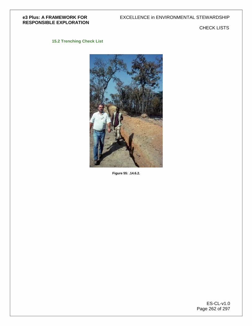
e3 Plus: A FRAMEWORK FOR EXCELLENCE in ENVIRONMENTAL STEWARDSHIP RESPONSIBLE EXPLORATION
CHECK LISTS
ES-CL-v1.0 Page 262 of 297
15.2 Trenching Check List
Figure 55: .14.6.2.

e3 Plus: A FRAMEWORK FOR EXCELLENCE in ENVIRONMENTAL STEWARDSHIP RESPONSIBLE EXPLORATION
CHECK LISTS
ES-CL-v1.0 Page 263 of 297
(Office Name)
1 of 4
ENVIRONMENTAL COMPLIANCE FORM TRENCHING (STRIPPED AREA) SITES
Please use ink
Project Name & Number: Work Permit No. Dates Excavated:
Trench No.: Location (attach map):
Contractor:
Field Geologist responsible for program:
Geologist/Technician responsible for site inspections:
Reclamation Complete Further Work Required
I, certify that all trenching procedures were done according to corporate exploration guidelines and have met all terms and conditions of all government permits and that the
site was left in a clean condition, in compliance with all corporate and government work permit standards.
___________________________________________________________ ___________________________ Contractor‟s Signature Date
I, certify that I have inspected the trench site and access road on the of , 20 , after the trench had been excavated and reclaimed (where applicable) and
that to the best of my knowledge all corporate and government permit standards have been met.
___________________________________________________________ ___________________________ Site Inspector's Signature Date

e3 Plus: A FRAMEWORK FOR EXCELLENCE in ENVIRONMENTAL STEWARDSHIP RESPONSIBLE EXPLORATION
CHECK LISTS
ES-CL-v1.0 Page 264 of 297
2 of 4
COMMENTS:
Attachments (Photos are mandatory - described, initialled and dated): Photos: Field Notes: Maps: Other:
Signatures: ___________________________________________________________ ____________________ Geologist in charge of program (in field) Date
___________________________________________________________ ____________________ Project, Senior Project or Senior Geologist (if applicable) Date
___________________________________________________________ ___________________ Regional Manager (mandatory) Date

e3 Plus: A FRAMEWORK FOR EXCELLENCE in ENVIRONMENTAL STEWARDSHIP RESPONSIBLE EXPLORATION
CHECK LISTS
ES-CL-v1.0 Page 265 of 297
3 of 4 TRENCH (STRIPPED AREA) SITE INSPECTION LIST
Overall Appearance of Site: Clean: Unclean:
Comments:
Trench: Filled in Yes No Comments
Reclaimed (i.e. reseeded) Yes No Comments
Picket with Tag Inscribed
With Trench Number Yes No Comments
Debris Left: (check) (amount/severity, etc.)
Leaners Comments:
Fill/Dirt Comments:
Metal/Wire/Cans Comments:
Containers (e.g. oil) Comments:
Tools, machine parts Comments:
Other (Specify) Comments:
Spills: Comments:
(severity/area)
Oil Yes No Comments: Soil Yes No Comments:

e3 Plus: A FRAMEWORK FOR EXCELLENCE in ENVIRONMENTAL STEWARDSHIP RESPONSIBLE EXPLORATION
CHECK LISTS
ES-CL-v1.0 Page 266 of 297
4 of 4
Date of Inspection: First Second Other
Inspected by: First Second Other
Further Cleanup Required: Yes No by Contractor by Company
(Specify Work)
Inspected by Government Officials: Yes No Date
Is Ministry Sign-off Required: Yes No
Cleared by Government Ministry: Yes No

e3 Plus: A FRAMEWORK FOR EXCELLENCE in ENVIRONMENTAL STEWARDSHIP RESPONSIBLE EXPLORATION
CHECK LISTS
ES-CL-v1.0 Page 267 of 297
15.3 Drill Site Check List
Figure 56: © Noranda/Falconbridge

e3 Plus: A FRAMEWORK FOR EXCELLENCE in ENVIRONMENTAL STEWARDSHIP RESPONSIBLE EXPLORATION
CHECK LISTS
ES-CL-v1.0 Page 268 of 297
(Office Name)
1 of 8
ENVIRONMENTAL COMPLIANCE FORM DRILL SITE - COLLAR & WATER SUPPLY
HOLE No:
Region: Project Name & No. Contractor: Dates Drilled:
(Drilling company responsible of drilling program) (Date drilling started and date drilling finish for this hole) Location: General Work Permit #
(UTM co-ordinates)
Grid
(Grid co-ordinates if drill hole located on a grid) Geologist Responsible for drill: Geologist/Geotechnician responsible for site inspection: Reclamation Complete YES NO Further Work Required YES NO
I, certify that all drilling procedures were carried out according to company exploration guidelines and have met all terms and conditions of all government permits and that the site was left in a clean condition, in compliance with all company and government work permit standards.
Contractor's Signature (or representative) Date I, certify that I inspected the drill site and access road on the of , 20 , after the drill had been removed, and that to the best of my knowledge all company and government permit standards have been met.
Site Inspector's Signature Date

e3 Plus: A FRAMEWORK FOR EXCELLENCE in ENVIRONMENTAL STEWARDSHIP RESPONSIBLE EXPLORATION
CHECK LISTS
ES-CL-v1.0 Page 269 of 297
2 of 8 COMMENTS:
Attachments (Photos of collar and water supply site are mandatory - described, initialled and dated): Photos: Field Notes: Maps: Other:
Signatures: Geologist in charge of program (in field) Date Project, Senior Project or Senior Geologist Date (if applicable) Regional Manager (mandatory) Date

e3 Plus: A FRAMEWORK FOR EXCELLENCE in ENVIRONMENTAL STEWARDSHIP RESPONSIBLE EXPLORATION
CHECK LISTS
ES-CL-v1.0 Page 270 of 297
(Office Name) 3 of 8
COLLAR SITE INSPECTION CHECKLIST
HOLE No: Overall appearance of the drill collar site - clean unclean
Comments: Drill collar
Casing pulled/date -yes no Hole cemented/date -yes no Capped -yes no Making water -yes no Casing damaged -yes no Picket with aluminium tag affixed -yes no Drill cuttings comments - Were drilling additives used? -yes no If yes, specify additives used Were oil licks used (absorbent carpeting)? -yes no Debris left (specify/check) (amount/area/severity etc.)
Metal, wire, rods, cans, cable comments - Fuel drums comments - Containers for oil, kutwell, grease comments - Tools, machine parts comments - Hose comments - Core boxes comments - Plastic tarps comments - Burlap, work gloves, clothing comments - Garbage bags comments - Food containers/wrappers comments - Absorbent padding/mud comments - Leaning trees comments -
Other comments Spills (amount/area/severity etc.)
Oil - yes no comments - Fuel - yes no comments -

e3 Plus: A FRAMEWORK FOR EXCELLENCE in ENVIRONMENTAL STEWARDSHIP RESPONSIBLE EXPLORATION
CHECK LISTS
ES-CL-v1.0 Page 271 of 297
4 of 8
Grease - yes no comments - Mud - yes no comments - All reportable spills Authorities notified?
MOE/Dept. of Environment (or equivalent) yes no MNR/Dept. of Natural Resources (or equivalent) yes no Company (which one?) yes no Fire pit
Applicable - yes no All contents burnt - yes no Contents remaining unburned: Wire - yes no Cans - yes no Foil - yes no Other - yes no Specify

e3 Plus: A FRAMEWORK FOR EXCELLENCE in ENVIRONMENTAL STEWARDSHIP RESPONSIBLE EXPLORATION
CHECK LISTS
ES-CL-v1.0 Page 272 of 297
(Office Name) 5 of 8
HOLE No: COLLAR SITE INSPECTION CHECKLIST
Water
Proximity of collar to running water or lake Approximate slope of ground
Condition of sump or berm Would silt clay run off into water if heavy rain occurred? Yes No Uncertain Should the site be re-examined when snow has melted, water level lower, etc.? Yes No Uncertain Suggested date: Reclamation
Hay spread yes no Trees planted yes no Site seeded yes no Other (specify)
WATER SUPPLY SITE INSPECTION CHECKLIST
Overall appearance of the water supply site - clean unclean
Comments: Debris left (specify/check) (amount/area/severity etc.)
Metal, wire, rods, cans, cable comments - Fuel drums comments - Containers for oil, kutwell, grease comments - Tools, machine parts comments - Hose comments - Core boxes comments - Plastic tarps comments - Burlap, work gloves, clothing comments - Garbage bags comments - Food containers/wrappers comments - Absorbent padding/mud comments - Leaning trees comments -
Other comments

e3 Plus: A FRAMEWORK FOR EXCELLENCE in ENVIRONMENTAL STEWARDSHIP RESPONSIBLE EXPLORATION
CHECK LISTS
ES-CL-v1.0 Page 273 of 297
6 of 8
Spills (amount/area/severity etc.)
Oil - yes no comments - Fuel - yes no comments - Grease - yes no comments - Mud - yes no comments - All reportable spills Authorities notified?
MOE/Dept. of Environment (or equivalent) yes no MNR/Dept. of Natural Resources (or equivalent) yes no Company Office (which one?) yes no Fire pit
Applicable - yes no All contents burnt - yes no Contents remaining unburned: Wire - yes no Cans - yes no Foil - yes no Other - yes no Specify

e3 Plus: A FRAMEWORK FOR EXCELLENCE in ENVIRONMENTAL STEWARDSHIP RESPONSIBLE EXPLORATION
CHECK LISTS
ES-CL-v1.0 Page 274 of 297
(Office Name) 7 of 8
HOLE No: WATER SUPPLY SITE INSPECTION CHECKLIST
Water
Proximity of collar to running water or lake Approximate slope of ground
Condition of sump or berm Would silt clay run off into water if heavy rain occurred? Yes No Uncertain Should the site be re-examined when snow has melted, water level lower, etc.? Yes No Uncertain Suggested date: Reclamation
Hay spread yes no Trees planted yes no Site seeded yes no Other (specify)
DATE OF INSPECTION first second other INSPECTED BY first second other
IS FURTHER CLEANUP OF COLLAR AREA REQUIRED?
No Yes By contractor by Noranda IS FURTHER CLEANUP OF WATER SUPPLY AREA REQUIRED?
No Yes By contractor by Noranda If yes specify what needs to be done and when:

e3 Plus: A FRAMEWORK FOR EXCELLENCE in ENVIRONMENTAL STEWARDSHIP RESPONSIBLE EXPLORATION
CHECK LISTS
ES-CL-v1.0 Page 275 of 297
(Office Name) 8 of 8
HOLE No: DRILL SITE INSPECTION PHOTOGRAPHS
DATE: DESCRIPTION: DATE: DESCRIPTION:

e3 Plus: A FRAMEWORK FOR EXCELLENCE in ENVIRONMENTAL STEWARDSHIP RESPONSIBLE EXPLORATION
CHECK LISTS
ES-CL-v1.0 Page 276 of 297
15.4 Stream Crossing Check List
Figure 57: © Golden Band

e3 Plus: A FRAMEWORK FOR EXCELLENCE in ENVIRONMENTAL STEWARDSHIP RESPONSIBLE EXPLORATION
CHECK LISTS
ES-CL-v1.0 Page 277 of 297
(Office Name) 1 of 3
ENVIRONMENTAL COMPLIANCE FORM STREAM CROSSING
(Required For Drill/Mechanized Trenching Programs) Please use ink
Project Name & Number: ______________________ Work Permit #: ______________________________
Dates Crossing in use: ________________________
Type of Crossing: ____________________________ Contractor: ________________________________
(Ford, Bridge, Ice, etc.) Date Temporary Crossing Removed: _____________________________________________________
Location of Crossing: _____________________________________________________
Field Geologist Responsible for program: _____________________________________________________
Geologist/Geotechnician responsible for site inspection: __________________________________________
Reclamation Complete __________________ Further Work Required _____________________
I, certify that this stream crossing was done according to company exploration guidelines and has met all terms and conditions of all government permits.
________________________________________________________ _____________________________________ Contractor's Signature Date
I, certify that this stream crossing was inspected by me on the of , 19 , after all crossings had been completed, and that to the best of my knowledge all
company and government permit standards have been met. ________________________________________________________ _____________________________________ Site Inspector's Signature Date

e3 Plus: A FRAMEWORK FOR EXCELLENCE in ENVIRONMENTAL STEWARDSHIP RESPONSIBLE EXPLORATION
CHECK LISTS
ES-CL-v1.0 Page 278 of 297
2 of 3
Has the water crossing been approved in the original work permit? Yes No Has a supplemental crossing permit been issued? Yes No If verbal permission has been given to use a water crossing, By Whom: ________________________________
Ministry: ________________________________
Date: ________________________________

e3 Plus: A FRAMEWORK FOR EXCELLENCE in ENVIRONMENTAL STEWARDSHIP RESPONSIBLE EXPLORATION
CHECK LISTS
ES-CL-v1.0 Page 279 of 297
(Office Name) 3 of 3
ENVIRONMENTAL COMPLIANCE FORM STREAM CROSSING
Please use ink
Are others using this crossing? Yes No If yes, details ________________________________________________________________________________
What equipment has used the water crossing and with what frequency? _______________________________________________________________________________________________
COMMENTS: _______________________________________________________________________________________________
Attachments (Photos are mandatory - described, initialled and dated): Photos: Field Notes: Maps: Other: _______________
Signatures: _________________________________________ _________________________________________ Geologist in charge of program (in field) Date ________________________________________ _________________________________________ Project, Senior Project or Senior Geologist Date (if applicable) ________________________________________ _________________________________________ Regional Manager (mandatory) Date

e3 Plus: A FRAMEWORK FOR EXCELLENCE in ENVIRONMENTAL STEWARDSHIP RESPONSIBLE EXPLORATION
CASE HISTORIES
ES-CH-v1.0 Page 280 of 297
16.0 Case Histories
The following case histories have been selected from submissions from EES users. They demonstrate the usefulness of the best practices outlined within the EES database and, in some cases, expand upon these practices. As always, we encourage users to submit additional case histories.
Figure 58: Use the best practices of EES and the following case histories to ensure the beauty of the land is left undisturbed after exploration is complete. © BHPBilliton.
16.1 Drilling from Lake Ice
Figure 59: Drilling at night from ice on Windy Lake, Sudbury, Ontario, Canada. © Graham Oxby

e3 Plus: A FRAMEWORK FOR EXCELLENCE in ENVIRONMENTAL STEWARDSHIP RESPONSIBLE EXPLORATION
CASE HISTORIES
ES-CH-v1.0 Page 281 of 297
Introduction
Wallbridge's Windy Lake Property is located near Levack, Ontario, Canada on the northwest edge of the Sudbury Igneous Complex. The property consists of the mineral rights under the lake. This and other properties are being explored in association with Lonmin Plc as the Sudbury Camp Joint Venture. Under terms of the joint venture, Lonmin is earning an interest in the properties. Wallbridge is the operator of the work programs. Although the Levack area some 5 kilometres to the east has seen extensive mining activity, the Windy Lake area has been largely undisturbed by this activity. No mining operations are visible from the lake. Windy Lake is a deep water, lake trout lake, with good water quality, over ten square kilometres in area. Mature trees surround the lake. Development on the lake is, for the most part, restricted to cottages with a lesser number of permanent residences and one golf course. Fishing in both summer and winter, boating, cross-country and water skiing, scuba diving, snowmobiling and sledding are among the popular recreational activities. Many local residents draw drinking water from the lake. The local residents are justifiably protective of this beautiful corner of Ontario. While the area is highly prospective for mineral discoveries, relatively little work has been done on or around the lake since the 1950's. Consequently, few of the people living in the area have never seen active exploration in the immediate area around the lake. Many of the people living on and using the lake were not predisposed to the prospect of mineral exploration and/or development. Concerns, suspicions and rumours abounded as to what impact mineral exploration might mean to the environment and quality of the lake. Stakeholder Concerns Wallbridge recognized early on that the concerns of the local residents had to be taken as seriously as the mineral potential if we were to be able to carry out a successful exploration program. The highest environmental standards had to be maintained and stakeholder concerns had to be addressed. The first step was a public meeting to announce our intentions, including an information session describing mineral exploration in general. The public was invited to present questions, concerns and suggestions. Many stakeholders attended the first public meeting. Their concerns were abundant, well articulated and persuasive. The attendees were however willing to listen to and consider the exploration proposal. As a result of that meeting, a committee of local representatives was formed to liaise with Wallbridge during our operations and look after the interests of the local stakeholders. The committee had members from no less than five stakeholder groups. To keep all residents informed as to our activities, we took out full-page information updates in the local newspaper on a biweekly basis. Initial Exploration Program Exploration proceeded in several phases. The first phase was an Audio-Magnetotelluric (AMT) survey on the lake, carried out in 2001. That survey involved taking readings on the ice using snowmobiles and using hand held Geographic Positioning Systems (GPS) for location. Other than skidoo tracks, there was no evidence of our presence on the lake. Subsequent magnetic and EM surveys were performed on the ice in the winter of 2002. This involved the establishment of a picket grid. Once the surveys were performed, the pickets were retrieved, once again leaving no evidence of our presence on the lake. A heavy snow that winter caused many of the pickets to be frozen into the ice, so the pickets were retrieved late in the winter.

e3 Plus: A FRAMEWORK FOR EXCELLENCE in ENVIRONMENTAL STEWARDSHIP RESPONSIBLE EXPLORATION
CASE HISTORIES
ES-CH-v1.0 Page 282 of 297
The winter of 2001-2002 was an unusually mild one. As a result, drilling was initiated from the shore in order to test some of the targets under the lake. Between March and December 2002, nine holes were drilled from land. These holes indicated the presence of favourable geology under the lake. It proved impossible to complete testing the entire area under the lake by drilling from shore. Drilling from the surface of the lake was required. Due to the depth of the lake (in excess of 100 m.) drilling from a barge with push-down legs was not feasible. 2002/2003 Ice Drilling Program
The Operations Plan
An operations plan was developed to test the geology under the northern part of the lake by drilling 10 holes from the ice. Rather than spread these holes out over many winters, it was decided to carry out all the drilling in one winter season should weather permit. This reduced the risk posed by unusually warm winters, such as 2001/2002, which did not generate enough ice to support the drilling rigs. A potentially short winter season left a very narrow window in which to complete the drilling program. Some holes were planned to be well over 1,000 meters deep. Being on the lake, it would be impractical, if not impossible to return to a partially completed deep drill hole. In order that the entire drilling program could be completed in a single season, the operations plan called for utilization of seven drill rigs. To our knowledge, that number of drills on a populated lake at one time is unprecedented in North America. Engineers from AMEC Earth and Environmental were contracted to help design and monitor the drilling. Boart Longyear, a company well experienced in drilling from the ice and with a good track record, was awarded the drilling contract. Sandwell Engineering of Calgary was contracted to design and monitor the ice pads for the drills. Together with this group of professionals, we developed the operations plan. Procedures were developed for every phase of the operation. Specific items addressed were:
1. Engineering and making ice pads that could support the weight of the drills, associated equipment and live loads.
2. Planning a safe means of moving equipment to and from the drill sites.
3. Rebuilding every drill with new seals and hoses to minimize the potential for leaks.
4. Equipping every drill with drip pans or double-walled tanks and absorbent pads wherever the possibility of a leak existed.
5. Planning safe movement of fuel and supplies to and from the drills.
6. Insulating every drill shack with sound absorbent material to minimize noise.
7. Equipping every drill with a muffler specifically designed for Windy Lake.
8. Using quadruple casing on the drill holes making a 4-times redundancy to ensure there would be no entry of drill water into the lake.
9. Filtering all cuttings from the drill water and re-cycling that same water back down the hole.
10. Eliminating the use of drilling additives, with the exception of a canola-based lubricant.
11. Equipping every drill with portable toilets.
12. Providing on site tours for local representatives and the general public.
13. Using helicopter support for moving drills and equipment.
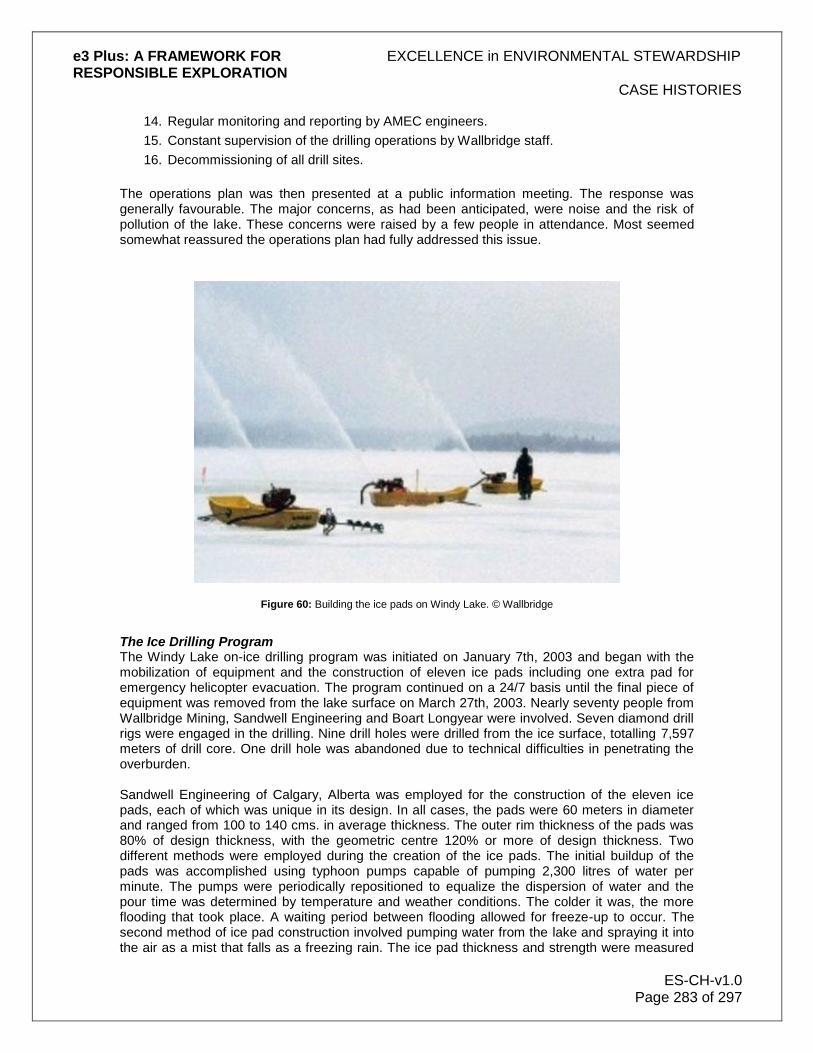
e3 Plus: A FRAMEWORK FOR EXCELLENCE in ENVIRONMENTAL STEWARDSHIP RESPONSIBLE EXPLORATION
CASE HISTORIES
ES-CH-v1.0 Page 283 of 297
14. Regular monitoring and reporting by AMEC engineers.
15. Constant supervision of the drilling operations by Wallbridge staff.
16. Decommissioning of all drill sites.
The operations plan was then presented at a public information meeting. The response was generally favourable. The major concerns, as had been anticipated, were noise and the risk of pollution of the lake. These concerns were raised by a few people in attendance. Most seemed somewhat reassured the operations plan had fully addressed this issue.
Figure 60: Building the ice pads on Windy Lake. © Wallbridge
The Ice Drilling Program The Windy Lake on-ice drilling program was initiated on January 7th, 2003 and began with the mobilization of equipment and the construction of eleven ice pads including one extra pad for emergency helicopter evacuation. The program continued on a 24/7 basis until the final piece of equipment was removed from the lake surface on March 27th, 2003. Nearly seventy people from Wallbridge Mining, Sandwell Engineering and Boart Longyear were involved. Seven diamond drill rigs were engaged in the drilling. Nine drill holes were drilled from the ice surface, totalling 7,597 meters of drill core. One drill hole was abandoned due to technical difficulties in penetrating the overburden. Sandwell Engineering of Calgary, Alberta was employed for the construction of the eleven ice pads, each of which was unique in its design. In all cases, the pads were 60 meters in diameter and ranged from 100 to 140 cms. in average thickness. The outer rim thickness of the pads was 80% of design thickness, with the geometric centre 120% or more of design thickness. Two different methods were employed during the creation of the ice pads. The initial buildup of the pads was accomplished using typhoon pumps capable of pumping 2,300 litres of water per minute. The pumps were periodically repositioned to equalize the dispersion of water and the pour time was determined by temperature and weather conditions. The colder it was, the more flooding that took place. A waiting period between flooding allowed for freeze-up to occur. The second method of ice pad construction involved pumping water from the lake and spraying it into the air as a mist that falls as a freezing rain. The ice pad thickness and strength were measured

e3 Plus: A FRAMEWORK FOR EXCELLENCE in ENVIRONMENTAL STEWARDSHIP RESPONSIBLE EXPLORATION
CASE HISTORIES
ES-CH-v1.0 Page 284 of 297
and recorded daily throughout the winter operations. This method was only utilized in ideal conditions. If the air was too cold, the spray came down as sleet rather than freezing rain, which was not desired. Ideally, the droplets are only partially frozen such that bonding and compression take place at the surface, producing a strong useable product. Progress of the ice thickness was measured daily using pickets and test holes. Upon completion, the ice pads were encircled by red/orange snow fencing equipped with amber flashing lights.
Figure 61: Mobilizing drill rig by helicopter onto Windy Lake. © Wallbridge
Onto each of the completed ice pads, untreated telephone poles (3-pole equivalents) were laid parallel to one another at a distance of two meters apart and secured to the ice by freezing. Removable plywood sheets with absorbent cloth were laid on logs. The absorbent material guaranteed that, in the event of a spill from the drill rig, no fluid would reach the ice surface. The platform was constructed in order to elevate the drill shack several cms. above the ice surface. This ensured a constant airflow under the drill so that any heat generated by the drill would not negatively affect the condition of the ice pad. Drills were placed as the pads were completed. The first drill rigs delivered were the 38's (least pad thickness required). Airlifting of the first diamond drill rigs began as soon as the first pads were completed. Drills were disassembled in a modular sense and gathered into approximately 1 tonne bundles. Each of the bundles was airlifted systematically to a predetermined ice pad, where the drill was reassembled. Drilling commenced on February 2nd, 2003 and continued until March 20th, 2003. Seven drill rigs of three different sizes were utilized: three Longyear 38's, two 44's and two 50's. Each of the drills has varying depth capacities: the larger the number, the deeper the drill capability. All of the drill holes were drilled perpendicular to the ice surface and ranged in depths from 100 to 1,500 metres. Prior to the drills arriving at Windy Lake, each of the seven drills was totally dismantled, assessed for its condition and cleaned and repaired as required. Every seal, gasket and hose was replaced and secured with new devices to minimize the potential for any breakdown as well as to ensure that no leakage of fluids. Each component of the diesel motor was tuned and adjusted to run at peak performance and to generate the least amount of noise.

e3 Plus: A FRAMEWORK FOR EXCELLENCE in ENVIRONMENTAL STEWARDSHIP RESPONSIBLE EXPLORATION
CASE HISTORIES
ES-CH-v1.0 Page 285 of 297
Enclosed drill shacks were constructed once the drill had been reassembled. Six-pound Fibrex acoustical board, designed to absorb sound generated by the machinery, lined interior walls. The acoustical board was held in place by chicken wire, thereby maximizing surface exposure essential for sound absorption. Four-foot high walled railings (also lined with 6-pound acoustical board) around the top of the drill shack were used as a safety railing feature as well as for sound reduction. In addition, half-inch rubber lining was used on all metal on metal contacts within the drill shack in order to help minimize noise. The drillers utilized rubber and plastic hammers in an effort to further reduce the noise generated by the drilling operation. Diesel engines were also fitted with specially designed muffler systems with a Fibrex lined baffle box. Drilling requires a substantial volume of water in order to cool the drill bit and clear rock chips generated as the drill bit penetrates into the rock. In a typical drill setup, drill water and rock chips are collected in a settling sump and the water is recycled back to the drill. The Windy Lake ice-drilling program utilized a closed system, allowing for no dispersion of materials. This was accomplished using a quadruple casing procedure. The first casing (H-size pipe) was suspended in the water to add rigidity to the inner pipes. The second casing (P-string) was lowered to the lake bottom and rotated to penetrate the lake bottom sediments and form an outer enclosure. When this casing was stabilized, a third smaller casing (N-string) was lowered through the center of the first two casings. At the same time, an outer plumbing system was attached to the outer larger casing in order to handle the drill water required to drill the internal casing into place. The N-string was then fitted with a diamond bit at the end capable of drilling into the bedrock below and establishing a permanent seal at the water-rock interface. When the N-string casing was properly secured and sealed, the smallest fourth casing (BW-string) was lowered through the N-string. The BQ-rod string, fitted with a regular coring bit, core tube and stabilizer was then lowered through to bedrock to continue drilling. The BQ-string was the only string that then rotated (cored). Within the drill shack, at the top of the quadruple casing, was a collection pan fitted with a sump pump feeding the cyclone. The cyclone separated drill water from rock chips, returning clean water back down the hole. Cyclone separated solids were collected in barrels and the liquid fraction directed to 2 or 3 settling tanks for additional cleaning. The final tank became the source of new drill water that was returned to the hole. The only time that lake water was used was to initially charge the system and then periodically to add water to increase volume with depth. The entire system was closed and there was no discharge into the lake. Rock chip cuttings were collected in the cyclone and emptied on a regular basis. The chips were placed in plastic-lined pails and transported off the ice to a dedicated container, which in turn was periodically collected by Day Environmental for disposal at a licensed disposal site. At the completion of the drill program, the remaining water in the closed system was decanted into containers and removed from site and disposed of in a similar manner as the rock chips.

e3 Plus: A FRAMEWORK FOR EXCELLENCE in ENVIRONMENTAL STEWARDSHIP RESPONSIBLE EXPLORATION
CASE HISTORIES
ES-CH-v1.0 Page 286 of 297
Figure 62: Aerial view of drill set-up, Windy Lake. © Wallbridge.
The main fuel storage for the drill program consisted of two 4,500-litre double-walled dyke tanks located adjacent to one another. These tanks were situated on the Windy Lake Gold Club, some 30 metres from the waterfront. A local licensed dealer periodically refilled the tanks. Each day, drill and heater fuel was pumped into two 450 litre certified Tidy Tanks. These smaller tanks were mounted in a "Monster Boggan" that served both as a means of transportation via ATV's and/or ski-doos to the drills as well as containment. Each drill site was equipped with a 700-litre stock tank, a tub-like container, which contained two standard 45-gallon drums, served as fuel tanks for the drill motor. Fuel feed lines, both internal and external, were tripled lined as a precaution to prevent leakage. Each drill shack was also equipped with an externally mounted dyke tank designed to service the internal heater. A trough lined with absorbent matting was located at the base of this tank to capture any spillage from the tank. All hose fittings were wrapped with absorbent material. Spill kits were located at all drill shacks as well as within the "Monster Boggan". Empty steel containers (one for oily waste and one for domestic waste) were located at each of the drill shacks for the disposable of all refuse. These containers were periodically transported by the "Monster Boggan" to the Windy Lake Golf Club site for disposal by a licensed carrier at a legal disposal site. Upon completion of the drill program, all drill holes were cemented and drill rods and related casings were removed from the lake surface and lifted to the shore in a manner similar to their delivery. All fluids (fuels, oils, lubricants and drill water), containers, refuse and related equipment used during the drilling operation were properly drained and removed from the ice utilizing pre-established procedures. All equipment was dismantled, packaged and airlifted to the pre-established marshalling yard then loaded and trucked from the site on a timely basis. Logs, pickets, fencing and flagging were totally removed, packaged and transported to the shore for proper disposal. All absorbent matting from under the drill shacks was removed and transported to shore for disposal at a licensed disposal site. Portable toilets and sewage related materials were removed in metal containments from the ice and disposed of by a contracted licensed carrier. All evidence of the ice operation was cleaned and disposed of in an appropriate manner. A consortium of Wallbridge representatives, Boart Longyear supervision, AMEC staff and a representative of the public agreed upon the "declaration of completion" for each drill site of the ice-drilling program. An engineer from AMEC Earth and Environmental monitored the drill program throughout its duration. Initial winter work involved the collection of (third pass) base-line water quality data on

e3 Plus: A FRAMEWORK FOR EXCELLENCE in ENVIRONMENTAL STEWARDSHIP RESPONSIBLE EXPLORATION
CASE HISTORIES
ES-CH-v1.0 Page 287 of 297
January 23rd, 2003 from six locations around the lake. A fourth set of samples was collected from the same six locations on April 3rd, 2003 following the completion of the drill program. Holes were drilled through the ice and the surrounding slush was allowed to freeze to ensure that the lake water samples were not contaminated by water ponded on top of the ice. Samples were submitted to Testmark Laboratories of Sudbury for chemical analyses. Pre and post water quality monitoring did not identify any increases in parameter concentrations associated with drilling activities. Total suspended solids and hydrocarbons remained below detection limits at all locations on both sampling occasions. Weekly inspections of all drill sites were also conducted by AMEC. These inspections involved noise abatement surveys, safety appraisals, compliance assessment and general housekeeping. Results and deficiencies were reported to Wallbridge and immediate remedial action was taken, as required. Representatives from the Ontario Ministry of the Environment conducted two separate field visits to observe the on-ice drilling operations. Feedback from the MOE following these visits was very positive. The on-ice drilling program was successfully completed in the winter of 2003. The measures employed in this program ensured that the local environment was unaffected, and no person was injured or property damaged.
16.2 Drilling in Environmentally Sensitive Tropical Areas
Figure 63: Can you spot where 5,000 meters of drilling was completed? For answer, see end of this case history. © Kluane Drilling.
In the mid to late 1990's, Energold Mining Ltd. planned a drilling program on the El Centenario gold prospect in central Dominican Republic, located approximately 75 km. northwest of Santo Domingo. (El Centenario is now defined as an epithermal deposit with a resource of 1.1 million tonnes grading 6.3 g/t Au.) Terrain and access were difficult and the planned program of shallow holes was relatively small. A forward-looking company, Energold wanted minimum disturbance in this environmentally sensitive area of dense tropical growth separated by areas with little

e3 Plus: A FRAMEWORK FOR EXCELLENCE in ENVIRONMENTAL STEWARDSHIP RESPONSIBLE EXPLORATION
CASE HISTORIES
ES-CH-v1.0 Page 288 of 297
vegetation and high visibility. All bids for drilling were inordinately expensive. Working with a private drilling company, Energold formed Kluane International Drilling Inc. (now 50% owned by Energold) to develop its own diamond drilling unit for the job. A lightweight, highly mobile, all hydraulic rig was selected. The program of 50 holes totalling 5,000 m. was efficiently completed with an all-in cost of US$72 per metre. Production averaged 28 m. per drill shift. Reclamation costs were very minimal and, as indicated by the accompanying photos, little if any physical evidence of the program remained after demobilization. The drilling program was audited by Cyprus/Amax and Kluane rigs modified to use a multiple engine concept were subsequently used by Cyprus on programs elsewhere in Central America, North America and Africa. Since then, these modular rigs have been used successfully in many other parts of the world where minimal environmental disturbance is required or desired and/or where access is difficult. As discussed below, a high altitude version is now available. In general, costs have been comparable to the original experience at El Centenario and productivity considerably improved.
Figure 64: Modular rig ready for mobilization to the project. © Kluane Drilling.
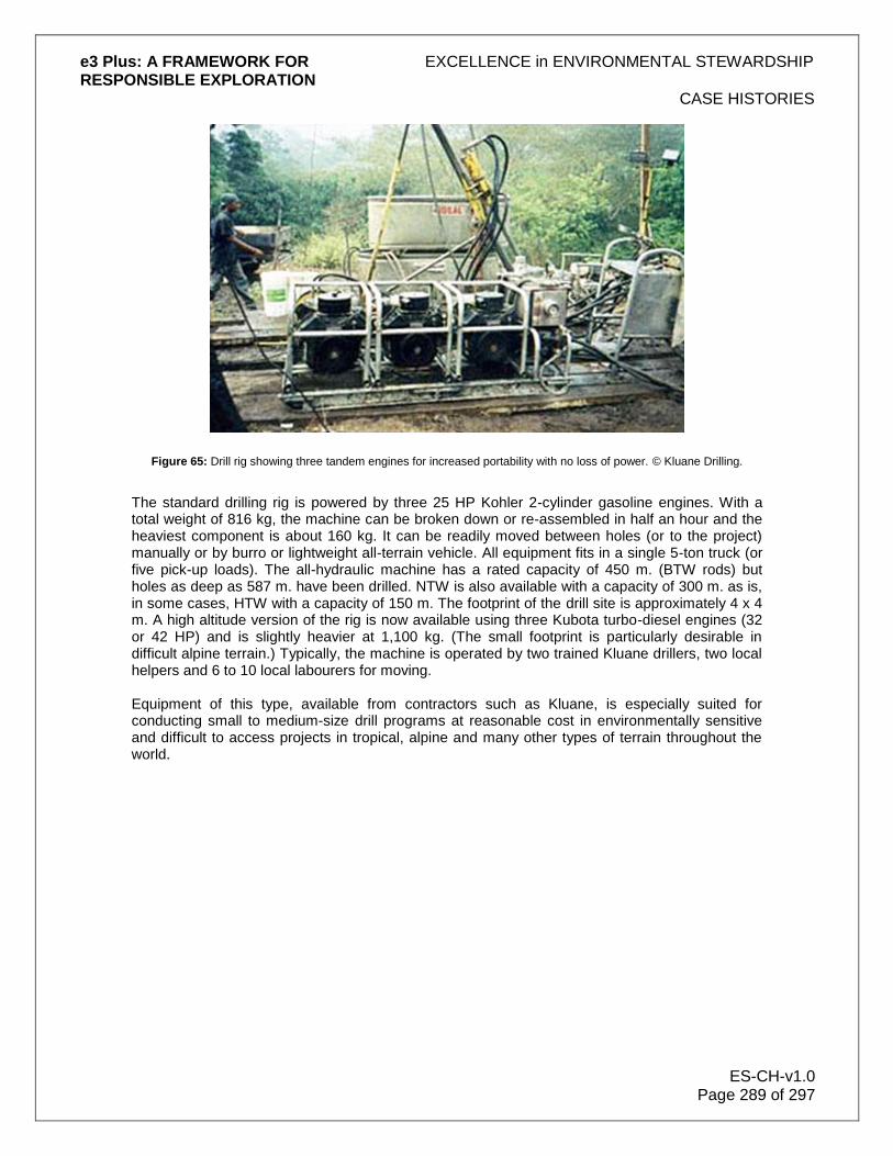
e3 Plus: A FRAMEWORK FOR EXCELLENCE in ENVIRONMENTAL STEWARDSHIP RESPONSIBLE EXPLORATION
CASE HISTORIES
ES-CH-v1.0 Page 289 of 297
Figure 65: Drill rig showing three tandem engines for increased portability with no loss of power. © Kluane Drilling.
The standard drilling rig is powered by three 25 HP Kohler 2-cylinder gasoline engines. With a total weight of 816 kg, the machine can be broken down or re-assembled in half an hour and the heaviest component is about 160 kg. It can be readily moved between holes (or to the project) manually or by burro or lightweight all-terrain vehicle. All equipment fits in a single 5-ton truck (or five pick-up loads). The all-hydraulic machine has a rated capacity of 450 m. (BTW rods) but holes as deep as 587 m. have been drilled. NTW is also available with a capacity of 300 m. as is, in some cases, HTW with a capacity of 150 m. The footprint of the drill site is approximately 4 x 4 m. A high altitude version of the rig is now available using three Kubota turbo-diesel engines (32 or 42 HP) and is slightly heavier at 1,100 kg. (The small footprint is particularly desirable in difficult alpine terrain.) Typically, the machine is operated by two trained Kluane drillers, two local helpers and 6 to 10 local labourers for moving. Equipment of this type, available from contractors such as Kluane, is especially suited for conducting small to medium-size drill programs at reasonable cost in environmentally sensitive and difficult to access projects in tropical, alpine and many other types of terrain throughout the world.

e3 Plus: A FRAMEWORK FOR EXCELLENCE in ENVIRONMENTAL STEWARDSHIP RESPONSIBLE EXPLORATION
CASE HISTORIES
ES-CH-v1.0 Page 290 of 297
Figure 66: Location of 5,000 meters of drilling as shown. © Kluane Drilling.
16.3 Value of EES in Permitting - A Case History from Brazil by Noranda/Falconbridge
Noranda was among the first companies, other than CVRD, to obtain exploration licenses inside the National Forests of the Carajas, Brazil. Access and mineral development in these areas are controlled through the government environmental agency IBAMA (Instituto Brasileiro de Meio Ambiente). These special reserves, usually covered with native rain forest, have been created by the federal government to avoid the degradation caused by undisciplined and illegal exploration and exploitation of its natural resources. With the recognized mineral endowment of the Carajas Province, the government has also however recognized the ability of the mining industry to produce sustainable economic and social development in these areas. The access and work permit application process has not yet been completely defined by IBAMA and each company in possession of mineral exploration licenses must rigorously demonstrate environmental and social responsibility by showing its exploration practices will have as little impact as possible. Noranda expects to receive its permits shortly, thanks in very large part to EES. Noranda's manager in Brazil realized that an application for initial reconnaissance exploration, hopefully leading to advanced drilling programs in this particular case, should include much more information than normal to facilitate the permitting process. As mentioned above, the local

e3 Plus: A FRAMEWORK FOR EXCELLENCE in ENVIRONMENTAL STEWARDSHIP RESPONSIBLE EXPLORATION
CASE HISTORIES
ES-CH-v1.0 Page 291 of 297
government department is not used to applications from major mining companies other than CVRD. Noranda turned to the PDAC's Excellence in: Environmental Stewardship in Exploration (EES) internet-based manual for help. EES has very detailed descriptions of acceptable and tested field operations from early-stage surveys to drilling. It includes clear and useful illustrations and diagrams. EES contains an enormous volume of detailed information describing almost all guidelines and best practices needed to produce these special applications for work in environmentally sensitive areas. In addition, Noranda's manager in Brazil feels that EES should be widely employed to provide basic professional development of local staff. This would reinforce the idea that well-thought out environmental planning for exploration activities would not only minimize the risk of future costly reclamation measures but also assist in building a solid and reliable reputation for Noranda with significant positive impact within the local community.
Figure 67: Preliminary exploration (auger drilling) in the rain forests of Carajas, Brazil. © Noranda/Falconbridge.
16.4 Reclamation of Steep Slope Access Roads - A Case History from AngloGold
Reclamation of mining land situated in hilly or mountainous terrain is often a daunting task. In North America, AngloGold staff have developed some novel approaches to reclamation of exploration tracks and mining haul roads. The Burns Basin area in the Independence Mountains, in the state of Nevada in the United States, is a beautiful area, with rocky outcrops and stands of aspen trees, home to deer, elk, mountain lion and the rare Northern Goshawk. The Burns Basin was part of the Jerritt Canyon mining project in Nevada. AngloGold's interest in Jerritt Canyon was sold to Queenstake Resources in 2003, but the mine was part of the AngloGold stable when the reclamation programme was initiated in 2001. Exploration drilling is required to prove the existence of a gold-bearing ore-body. With mountainous terrain comprising a large part of the mining lease, the construction of tracks, criss-crossing the hills, was necessary for drill rigs to access the desired drill locations. Unrehabilitated these tracks would leave a damaging scar on the hilly landscape. However, impressive rehabilitation of these tracks has been achieved, relatively inexpensively, using a

e3 Plus: A FRAMEWORK FOR EXCELLENCE in ENVIRONMENTAL STEWARDSHIP RESPONSIBLE EXPLORATION
CASE HISTORIES
ES-CH-v1.0 Page 292 of 297
excavator to remove the tracks. The area is then replanted with an indigenous grass seed mix, fertilised and left to recover. The photographs show how the original profile of the slope is restored by cutting-down the upper slope and pulling-up material from the down-slope. Having proved the existence of a viable gold-bearing ore-body, the mine is planned and haul roads are constructed to gain access to the mine pit. These haul roads must be capable of carrying 100 tonne dump trucks and are therefore a lot bigger than the exploration tracks. Jeff Campbell, Senior Environmental Coordinator, explains how haul roads are rehabilitated: "The topography in the Jerritt Canyon Project area often makes full recontour of haul roads a challenging undertaking. The existing slopes along the Burns Basin haul road range from 30% to 50%. Such steeply sloping areas used to receive only a partial recontour, leaving a small portion of the cut slope unreclaimed: this was because of the high costs of recontouring steeply sloping land. Previous experience at Jerritt Canyon has shown that haul road reclamation on moderate to steep slopes can be done in the range of US$12 to US$18 per linear foot (approximately 0.31 metres) of 80-foot (~25 metres) haul road. However, the Burns Basin haul road was a special case. The haul road is situated in the southwest portion of the Jerritt Canyon Project at an elevation of 7,900 feet (2,400 metres). Even though the approved reclamation plan for the haul road did not require full recontour of the road, our goal was to reclaim as much as possible back to original topography. There were a number of reasons for this, the first being that it is a beautiful portion of the Independence Mountains with rocky outcrops and significant aspen stands which are habitat for deer, elk, mountain lion, and Northern goshawk. Secondly, the Burns Basin haul road is situated high on a ridge which can be seen from most portions of the drainage basin area. Reclamation of portions of the primary haul road network began in the late summer of 2001. Approximately 12,000 feet (~3.6 kilometres) of 80-foot wide (~25 metres) haul road was recontoured to the original topography and re-seeded. This project represented the first significant attempt at the Jerritt Canyon Project for full recontour of haul roads in areas exceeding 30% side slope while keeping reclamation costs within a reasonable range. The 2001 Reclamation Programme was awarded to a local reclamation contractor in Elko, Nevada. After reviewing the project area and discussing the reclamation goals with AngloGold's Environmental Resources Department at Jerritt Canyon, the contractor decided to use two hydraulic excavators with two support dozers. The excavators consisted of one Caterpillar 345B and one 365B along with two D8 dozers. The recontouring process utilises the two excavators in tandem, with one excavator on a lower bench reaching to the toe of the fill slope and casting material to the second excavator on an upper bench where a portion of the material is moved in a second "pass" to a support dozer. Depending on the steepness of the topography, two, three, and sometimes four "passes" may be required to retrieve material from the toe of the fill slope and redistribute material to the top of the cut slope. One or two dozers have proved to be very effective in redistributing material brought up by the excavators to achieve a full recontour of the cut slope and for final shaping of the recontoured slope.

e3 Plus: A FRAMEWORK FOR EXCELLENCE in ENVIRONMENTAL STEWARDSHIP RESPONSIBLE EXPLORATION
CASE HISTORIES
ES-CH-v1.0 Page 293 of 297
Figure 68: Road reclamation usually involves two excavators working in tandem. The original slope is restored by cutting
down the upper slope and pulling up material from the lower slope. © AngloGold.
While this recontouring technique is not a new one, the challenge is to achieve a full recontour while maintaining a cost effective reclamation programme. Previous projects were not done to full recontour. The Burns Basin haul road was recontoured to original topography in areas of 30% to 50% side slopes for about US$17 per linear foot (costs quoted are $2001). Returning the land to its original contours represented only the first step of the project. After completion of the recontouring, the entire area was broadcast seeded and fertilised in the fall of 2001. The recontoured slopes were fertilised with 350 pounds per acre of inorganic fertiliser. Then, the reclamation seed mix, consisting of 22 species of grasses and shrubs, was broadcast and harrowed. In addition, 2,500 aspen seedlings, grown from seed collected at Jerritt Canyon, were planted in five areas along the Burns Basin haul road where aspen had been removed during the construction of the road. The aspen seedlings should accelerate the rejuvenation of the aspen stands along the haul road reclamation. In conclusion, Jeff points out that, even though overall cost was a consideration during this project, the primary goal was to achieve an aesthetically pleasing reclamation project in the Burns Basin area. Cost effective implementation of any reclamation project is enhanced when the contractor and/or equipment operator understands the reclamation goal and strives to meet that goal through genuine interest in the project and the final product. The steep slope reclamation of the Burns Basin haul road demonstrates a successful reclamation strategy, where neither the overall project economics nor the final reclamation goal were compromised to achieve the desired outcome.

e3 Plus: A FRAMEWORK FOR EXCELLENCE in ENVIRONMENTAL STEWARDSHIP RESPONSIBLE EXPLORATION
CASE HISTORIES
ES-CH-v1.0 Page 294 of 297
Figure 69: Reclaimed roads six months after restoration. Old exploration tracks are still Visible but indigenous grass seed will gradually mix with the neighbouring vegetation to largely eliminate any scarring. © AngloGold.
16.5 Community Engagement during Exploration in Brazil - A Case History from Gold Fields
Gold Fields Exploration concluded its exploration program on the Capanema Project, Para State, Brazil, in December 2003. In this remote region, far from professional medical help, economic opportunities and governmental assistance, the needs are basic and include health care, sanitation, access to drinking water, jobs, housing, education and infrastructure. Gold Fields´ presence created a sense of hope within communities suffering from a general lack of economic opportunity. Unfortunately, the Capanema project was closed before some of the planned programs were implemented. The exploration team was successful in creating a spirit of goodwill and cooperation with the community, and we learned about their many needs. The interaction with the community was honest and transparent. The community recognized the benefits and risks related to our activity, and all efforts were made to make them aware of the temporary nature of the exploration process. Most of the activity involved low-impact work, such as opening trenches for sample collection, as well as some drilling. We rehabilitated affected areas by refilling and restoring vegetation to all trenches and drill holes. Through engagement in an open, honest, and effective process of consultation and communication with the local community, throughout all stages of our operations, Gold Fields developed programs targeting their most urgent needs. This resulted in extensive support for the company's activities in the area. In addition to the remedying of the unavoidable environmental impact that results from exploration activities, our goals were the creation of both economic and environmental rewards, producing a net gain for the community.

e3 Plus: A FRAMEWORK FOR EXCELLENCE in ENVIRONMENTAL STEWARDSHIP RESPONSIBLE EXPLORATION
CASE HISTORIES
ES-CH-v1.0 Page 295 of 297
Figure 70: Acai plantation operated by local people and developed from seeds donated by Gold Fields. © Gold Fields
Gold Fields hired and trained local inhabitants, providing legal personal documentation and wages above the regional average. Some infrastructural improvements were initiated. Roads were repaired, benefiting the agricultural families, but after closure of operations their maintenance cannot be guaranteed. Water wells were planned in an attempt to help alleviate the chronic lack of potable water in the region. One was dug and remains operational, however the problem persists. The establishment of an Agricultural Cooperative for selling local produce was not successful. We were unable to continue providing mentorship and assistance in its administration and commercialization. Without our continuous presence in the area the demand for goods would not be sufficient to cover its costs. Thousands of açai seeds donated by Gold Fields to the local community were planted. The fruit is rich in iron and has a high export potential, and the plantation now remains under their responsibility and care. Gold Fields initiated a recycling education program to teach the economic and ecological benefits of selective waste collection, which continues at the primary level. At the end of the contract all the employees were dismissed according to Brazilian Labour Legislation with no reclamations. Our closure was completed respecting our environmental responsibilities. Revegetation has been successfully concluded.

e3 Plus: A FRAMEWORK FOR EXCELLENCE in ENVIRONMENTAL STEWARDSHIP RESPONSIBLE EXPLORATION
CASE HISTORIES
ES-CH-v1.0 Page 296 of 297
Figure 71: Area of trenching before reclamation. © Gold Fields.
Figure 72: Same area of trenching six months after reclamation. © Gold Fields
Conclusion - How could we improve future operations based on experiences? By nature, the exploration phase is temporary and its outcome is uncertain. While we seek to promote lasting benefits to the communities during the exploration phase that could be extended throughout and beyond closure, sustainable programs are best achieved through education. For
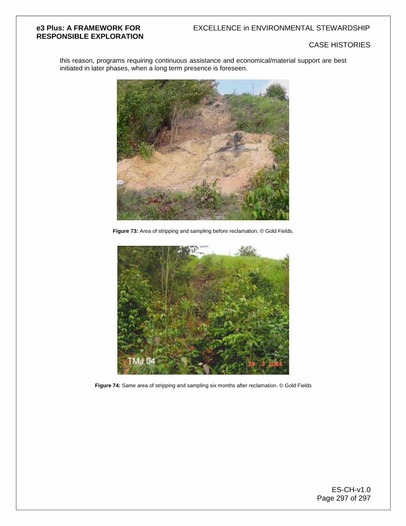
e3 Plus: A FRAMEWORK FOR EXCELLENCE in ENVIRONMENTAL STEWARDSHIP RESPONSIBLE EXPLORATION
CASE HISTORIES
ES-CH-v1.0 Page 297 of 297
this reason, programs requiring continuous assistance and economical/material support are best initiated in later phases, when a long term presence is foreseen.
Figure 73: Area of stripping and sampling before reclamation. © Gold Fields.
Figure 74: Same area of stripping and sampling six months after reclamation. © Gold Fields