excellent dosing - zkg.de · cal roller grinding mill, rotary kiln, or separator drives – each...
TRANSCRIPT

ExcellentDosing
Cement Lime Gypsum Zement Kalk Gips
www.zkg.de
INDIA SPECIALISSUE 1 2014
PROCESS // AFR
Destruction of hazardous chemicals and POPs in cement kilns 26
EVENTS // Company anniversaryStrong development over 150 years 06
ENGINEERING // Plant performanceTrends in the performance management of cement plants 12
PROCESS // AFRProven experiences with alternative
PLANT REPORT // GrindingSubstantial gain in cement mill output
fuels in the cement kiln process 20
with minor investment – a case study 08
LOESCHE GmbHHansaallee 243D-40549 Düsseldorf, Germanywww.loesche.com
Three guarantees ensuring your success in the world’s comminution markets:
• Outstanding in competence, technology, flexibility and reliable service.
• Sensitive about the needs of our customers to whom we carefully listen and for whom we develop smart solutions.
• Key competence and creative advice that give you confidence.

TURNING IDEAS INTO T E C H N O L O G Y

2 ZKG India Special www.zkg.deZKG 1 2013 2
Clinker hopper
Vibrating screen
Fly ash silo - 4mm
Clinker bin
Gypsum hopper
Cement mill
Fly ash bin
Trommel screen (-4mm)
Separator
Cyclone
Vertical pneumatic conveyor
Silo 1 Silo 2 Silo 3
Mill vent BF
Mill ventfan
VSI Crusher
Packer
Solid flow meter
Weigh feeder
Weigh feeder
Page 8Substantial gain in cement mill output with minor investment – a case study
Page 12Trends in the performance management of cement plants
Page 20Proven experiences with alternative fuels in the cement kiln process
Page 26 Destruction of hazardous chemicals and POPs in cement kilns
SPECIAL INDIACement Lime Gypsum
COMPANY PROFILES
3 Köppern
4 SICIT Group
5 Siemens
PROJECTS AND ACTIVITIES
6 Gebr. Pfeiffer SE Strong development over 150 years
8 UltraTech Cement Ltd. Substantial gain in cement mill output with minor investment –
a case study Shyamal Roy, Sanjeev Srivastava and L. Rajasekar, T
echnical Research Centre, UltraTech Cement Ltd., Mumbai/India
12 OneStone Consulting Trends in the performance management of cement plants Dr. Joachim Harder, OneStone Consulting S.L., Barcelona/Spain
20 ZKG International Proven experiences with alternative fuels
in the cement kiln process Dr. Hubert Baier, ZKG International, Gütersloh/Germany
26 SINTEF Destruction of hazardous chemicals and POPs in cement kilns Dr. Kåre Helge Karstensen, Chief Scientist,
Foundation for Scientific and Industrial Research – SINTEF, Oslo/Norway
32 IMPRINT
32 ADVERTISER INDEX
32 EVENT PREVIEW
ExcellentDosing
Cement Lime Gypsum Zement Kalk Gips
www.zkg.de
INDIA SPECIALISSUE 12014
PROCESS // AFR
Destruction of hazardous chemicals and POPs in cement kilns 26
EVENTS // Company anniversaryStrong development over 150 years 06
ENGINEERING // Plant performanceTrends in the performance management of cement plant 12
PROCESS // AFRProven experiences with alternative
PLANT REPORT // GrindingSubstantial gain in cement mill output
fuels in the cement kiln process 20
with minor investment – a case study 08
The strength of worldwide operating FLSmidth Pfister GmbH is development and manufacturing of sophisticated continuous weighing and dosing systems for all stages of cement production. This month’s cover shows rotor weighfeeder Pfister® DRW for dosing pulverized fuels such as petrolcoke, lignite or coaldust. More than 2.500 installations in cement plants have proved its accuracy and constancy. Many features like inlineblending of different fuels and the powerful dosing strategy ProsCon® support its reliable performance.
www.flsmidthpfister.com
CONTENT
Company profile // INDIA SPECIAL
ZKG India Special 3
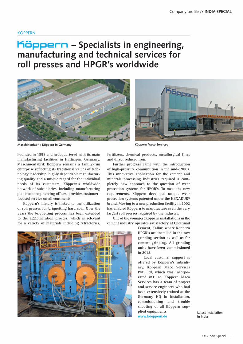
Founded in 1898 and headquartered with its main manufacturing facilities in Hattingen, Germany, Maschinenfabrik Köppern remains a family-run enterprise reflecting its traditional values of tech-nology leadership, highly dependable manufactur-ing quality and a unique regard for the individual needs of its customers. Köppern’s worldwide network of subsidiaries, including manufacturing plants and engineering offices, provides customer-focused service on all continents.
Köppern’s history is linked to the utilization of roll presses for briquetting hard coal. Over the years the briquetting process has been extended to the agglomeration process, which is relevant for a variety of materials including refractories,
fertilizers, chemical products, metallurgical fines and direct reduced iron.
Further progress came with the introduction of high-pressure comminution in the mid-1980s. This innovative application for the cement and minerals processing industries required a com-pletely new approach to the question of wear protection systems for HPGR’s. To meet the new requirements, Köppern developed unique wear protection systems patented under the HEXADUR® brand. Moving to a new production facility in 2002 has enabled Köppern to manufacture even the very largest roll presses required by the industry.
One of the youngest Köppern installations in the cement industry operates satisfactory at Chettinad
Cement, Kallur, where Köppern HPGR’s are installed in the raw grinding section as well as for cement grinding. All grinding units have been commissioned in 2012.
Local customer support is offered by Köppern’s subsidi-ary, Koppern Maco Services Pvt. Ltd, which was incorpo-rated in1997. Koppern Maco Services has a team of project and service engineers who had been extensively trained at the Germany HQ in installation, commissioning and trouble shooting of all Köppern sup-plied equipments.www.koeppern.de
KÖPPERN
– Specialists in engineering, manufacturing and technical services for roll presses and HPGR’s worldwide
Köppern Maco ServicesMaschinenfabrik Köppern in Germany
Latest Installation in India

INDIA SPECIAL // Company profile
www.zkg.de4 ZKG India Special
SICIT Group structure » SICIT S.p.A.: is the holding company founded
in 1960. In over 50 years we have built two manufacturing plants located in Chiampo and Arzignano (Vicenza).
» SICIT 2000 S.p.A.: the production and market-ing Company in charge of the management of the plants where raw material is treated to pro-duce amino acids, peptides and their deriva-tives. The plants work under HACCP control.
SICIT Group the worldwide leader in manufacturing aminoacids & peptides based products
» SICIT CHEMITECH S.p.A.: is the engineering company also in charge of the R&D and Quality Control, which ensures safe and reliable manu-facturing process through its quality control labs for chemical and bacteriological analysis. It also develops new products and engineering technologies.
The amino acids based products manufactured by SICIT 2000 found their use in the following sectors: » Agriculture (special fertilizers & plant growth
regulator), » Building industry (multifunctional additives
for gypsum), » Cosmetic; » Detergency.
SICIT GROUP has 100 workers, who’s efforts permit to manufacture high quality products distributed in over 70 countries through worldwide collabo-ration with Multinational Companies and a large distribution network. We mainly manufacture high quality products for Multinational Companies that guarantee the packaging and distribution under their own trademark.
Building SectorPlast Retard are nowadays the most used and efficient multifunctional additives in the gypsum industry thanks to their standardized quality. Moreover, because of their natural origin they are not hazardous for the workers and eco-friendly.
Aerial view of our newest plant opened in 2004
HPLC to determine the molecular weight distribution of hydrolyzed proteins in our products
Plast Retard
SICIT

Company profile // INDIA SPECIAL
ZKG India Special 5
Integrated solutions for the cement industryWhether crusher, roller press, tube mill, verti-cal roller grinding mill, rotary kiln, or separator drives – each application is in safe hands with Siemens. We provide the entire product range in the highest quality, starting with controls, fre-quency inverters, motors, couplings and clutches, progressing through helical, bevel-helical and planetary gear units, and continuing with add-on pieces.
With the highest product and application ex-pertise Siemens Drive Technologies links auto-mation, drive, and power supply systems to form one overall solution, based on the Integrated Drive System (IDS) concept. FLENDER mechanical
power transmission technology is an in-tegral part of IDS. FLENDER drive com-ponents convince due to highest prod-uct and manufacturing quality, fast availability worldwide, and an attractive price level.
With a global workforce of more than 100,000 em-ployees, Sie-mens Drives Technologies Divsion ensures the highest produc-tivity due to maximum machine uptime.
The widely diversified portfolio sup-plies comprehensive solutions as well as standard products that meet exactly Siemens customer’s re-quirements. Siemens is the world’s leading sup-plier of innovative and environ-mentally friendly automation and drive technology, industrial soft-ware and technology-based services.
For more information and technical descriptions, click on the “Support” navigation point on our Website.www.siemens.com/flenderapplications orwww.siemens.com/cementContact: [email protected]
SIEMENS
For highest plant availability
Bucket elevator drive: integrated standard-ized drive system for bucket elevators – in-verter, motor, coupling, auxiliary motor and gear unit from a single source
FLENDER MultipleDrive: the new drive concept unites the benefits of a variable-speed drive with the modularity of a multi-stage drive that enables the system to be continuously available. It opens up new dimensions for power transmission up to 16.5 megawatt
www.zkg.de6 ZKG India Special
SPECIAL // India
Gebr. Pfeiffer was founded in 1864 as a small ma-chine factory in Kaiserslautern/Germany. Today, it is a globally active company with subsidiaries in India, in the United States and China and about 500 employees worldwide. In the founding years steam engines, mills for food production and malt-ing equipment were the main products of the com-pany, but the focus very soon turned to machines and plants for the basic materials industry as we learn from an exhibition catalog “Machines for Hard Comminution” published in 1892 (Fig. 1).
Gebr. Pfeiffer – GPSE today – has always strived to supply its customers with particularly efficient and reliable machines. In retrospect, it is not sur-prising that you find superlatives again and again like “the first mill”, “the largest mill”, “the best workmanship”, “the longest durability” (Fig. 2). True to his motto that “If you rest you rust!” the company founder Jacob Pfeiffer motivated his em-ployees time and time again to perform to their utmost ability. The first air separators for the ce-ment industry (1890) were manufactured during his active business life. Before the beginning of World War 1 in 1914, Gebr. Pfeiffer already em-ployed 500 people in Kaiserslautern and exported 75 % of its machines.
The two World Wars (1914-1918 and 1939-1945) saw Gebr. Pfeiffer, which was an interna-tional and export-oriented company, suffer serious setbacks, in its entrepreneurial development: Sales markets were no longer accessible, and production plants were destroyed by the war and disassembled afterwards as reparations. Yet, after each setback Gebr. Pfeiffer recovered quickly and today in the 150th year of its company history Gebr. Pfeiffer demonstrates its technological leadership through
the world´s largest cement mill, an MVR 6700 C-6 with an 11,500 kW MultiDrive®, currently under erection in Barroso, Minas Gerais/Brazil for Holcim Brazil.
Gebr. Pfeiffer sold its first own vertical mill in the year of 1956, which has become a success story under the name of the MPS mill. It was a signifi-cant contributing factor to the company’s current success and the mill has been sold several thousand times over the years by GPSE and its licensees. The MPS mill was also the world’s first vertical mill for cement grinding that was installed in Germany in 1979.
GEBR. PFEIFFER SE
Strong development over 150 years
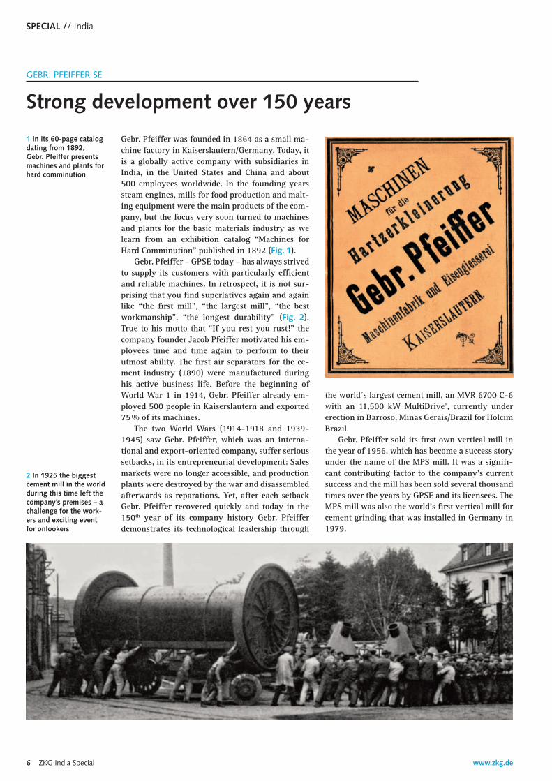
2 In 1925 the biggest cement mill in the world during this time left the company’s premises – a challenge for the work-ers and exciting event for onlookers
1 In its 60-page catalog dating from 1892, Gebr. Pfeiffer presents machines and plants for hard comminution

India // SPECIAL
Today, in terms of reliability and cost efficien-cy, the MPS mill is worldwide considered the best solution for small and medium capacities in the field of raw material, coal and cement grinding. For large and extra large capacities, starting with an installed power of 5000 kW, the MPS mill acquired a big sister, the MVR mill, which was put on line for the first time in 2008. Nowadays, MVR mills for raw material and cement grinding are operating to the entire satisfaction of Gebr. Pfeiffer’s custom-ers in Europe, Asia and Australia (Fig. 3) and more MVR mills will go onstream shortly in North and South America and in more countries in Asia.
In addition to the technically excellent prod-uct range, Gebr. Pfeiffer’s endeavour is always to render the very best services concerning the mill to its customers. This starts with the planning and construction of complete grinding plants, reaching
3 The largest cement mill in Australia has been operating since 2014
textile packaging consumer bags| | |
from training programmes and plant optimisa-tions through to repairs, modernisations and up-grades. Moreover, the portfolio includes the supply of spare parts which for mill components can be made available 40, 50 or even 60 years after their delivery, thanks to GPSE’s own flexible workshops in Kaiserslautern.
Apart from continuously working on innova-tions to the benefit of the customers and true to its company’s motto “Progress is our tradition”, an-other success factor of Gebr. Pfeiffer has been con-tinuity – free from management fads – of staff and management. Many staff members at Gebr. Pfeiffer celebrate their 25th, 40th or even 50th anniversary with the company. Staff fluctuations are not an is-sue and over the 150 years of the company’s his-tory the average employment period of the execu-tive board members is 18 years.
The customers. however, who decide over and over again in favour of Gebr. Pfeiffer’s machines and plants, sharing their positive experience with other customers, are the most important factor for the company´s success. On May 8th/9th, 2014 Gebr. Pfeiffer will celebrate the company’s 150th anni-versary with these faithful customers and thereby not only look back on past achievements but also make plans for the future true to the company founder’s motto “If you rest you rust!”. www.gpse.de
www.zkg.de8 ZKG India Special
SPECIAL // India
www.zkg.de
Clinker hopper
Vibrating screen
Fly ash silo - 4mm
Clinker bin
Gypsum hopper
Cement mill
Fly ash bin
Trommel screen (-4mm)
Separator
Cyclone
Vertical pneumatic conveyor
Silo 1 Silo 2 Silo 3
Mill vent BF
Mill ventfan
VSI Crusher
Packer
Solid flow meter
Weigh feeder
Weigh feeder
1 IntroductionThe manufacturing process of cement is a highly electrical energy intensive process. Size reduction in a plant consumes 55-65 % of the total electrical energy consumption accounting for 30-40 % of the total production costs. So, a ball mill used for ce-ment production consumes nearly 30-35 % of total power consumption of the plant. Hence the impact of ball mill productivity enhancement has substan-tial influence on manufacturing cost reduction.
In our group, the ball mill output ranges from as low as 52 tph to as high as 290 tph with power con-sumption ranging from as low as 20 kWh/mt to as high as 36 kWh/mt. The large difference in mill TPH and specific power consumption is dependent on many factors starting from selection of equipment, grinding media distribution, liner condition, sepa-rator condition, process flow sheet, input material granulometry, material hardness, material fine-ness, input moisture, clinker microstructure, clinker chemistry and most importantly process operating
condition. In this article, substantial increase in ce-ment mill output (~ 20 %) and reduction in specific power consumption of one of the ball mills with minor investment has been discussed.
2 Observation and analysis during studyThe cement mill is a closed circuit ball mill (3.2 m diameter and 12.07 m length) with installed mo-tor power of 1680 kW and supported on trunnion bearings. The separator has horizontal guide vanes. The feeding of the material to the separator is from
ULTRATECH
Substantial gain in cement mill output with minor investment – a case study
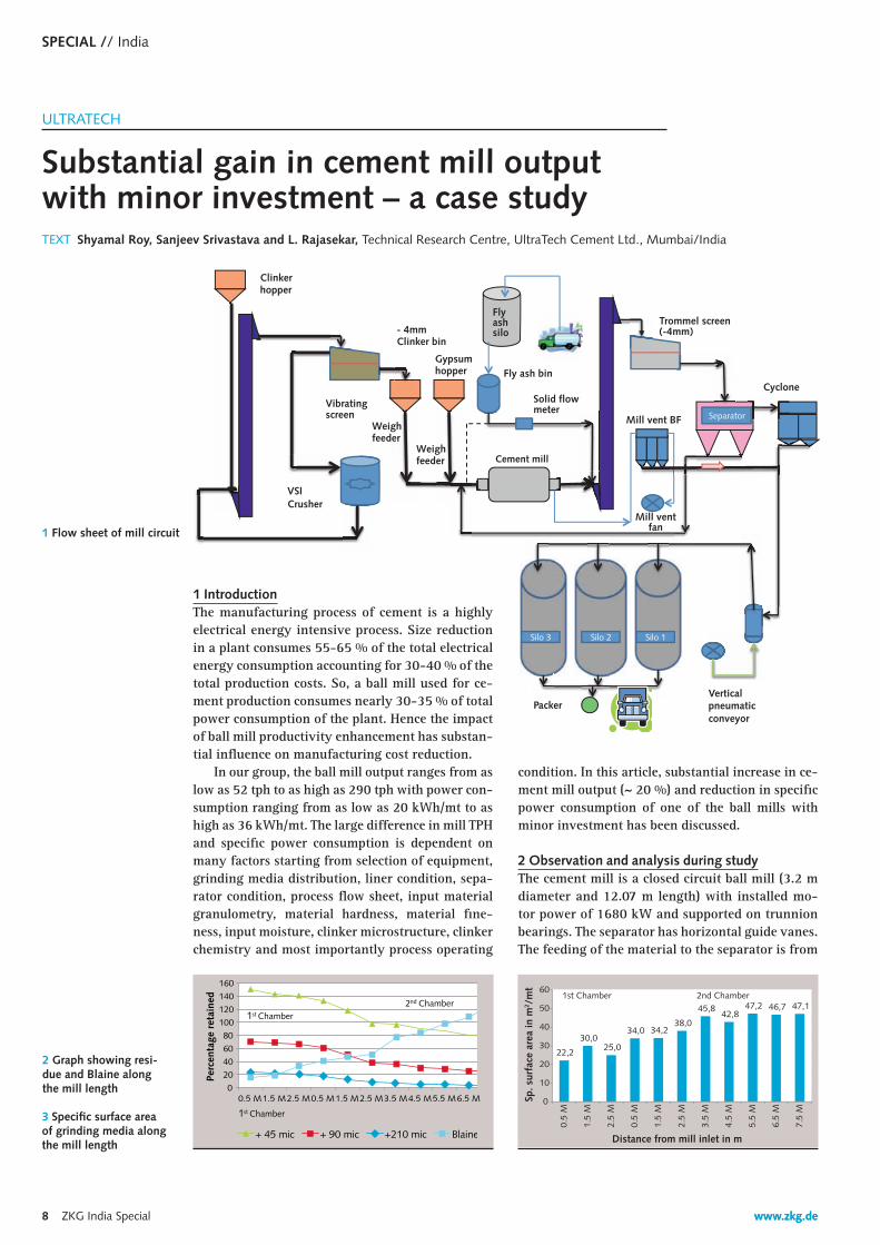
1 Flow sheet of mill circuit
TEXT Shyamal Roy, Sanjeev Srivastava and L. Rajasekar, Technical Research Centre, UltraTech Cement Ltd., Mumbai/India
0 20 40 60 80
100 120 140 160
0.5 M 1.5 M 2.5 M 0.5 M 1.5 M 2.5 M 3.5 M 4.5 M 5.5 M
Perc
enta
ge r
etai
ned
+ 45 mic + 90 mic +210 mic Blaine
1st Chamber 2nd Chamber
6.5 M
1st Chamber
2 Graph showing resi-due and Blaine along the mill length
22,2
30,0 25,0
34,0 34,2 38,0
45,8 42,8
47,2 46,7 47,1
0
10
20
30
40
50
60
0.5
M
1.5
M
2.5
M
0.5
M
1.5
M
2.5
M
3.5
M
4.5
M
5.5
M
6.5
M
7.5
M Sp
. sur
face
are
a in
m2 /
mt
Distance from mill inlet in m
1st Chamber 2nd Chamber
3 Specific surface area of grinding media along the mill length

ZKG India Special 9
India // SPECIAL
the top and split into two different locations. The mill is used to produce PPC with Blaine ~ 330-340 m2/kg. The clinker is preground in a vertical shaft impactor (VSI), followed by screening through a deck screen with 4 mm mesh.
The undersized clinker material from the deck screen plus gypsum is fed together into the mill inlet and dry fly ash is fed directly at the separator inlet. The coarse material from the separator is also fed to the mill inlet. The capacity of the mill was 62 tph, with 336 m2/kg Blaine with specific power at 32.5 kWh/mt for grinding. Looking at mill dimensions and present output figure, it was felt that there is a scope of improvement in output with reduction of specific power consumption. Hence, a technical evaluation study was con-ducted to find out the scope for improvement with minimum investment. Mill and separator performance data, circuit and chamber samples were collected and then analysis was car-ried out to indentify the cause of poor productivity. Mill pro-cess flow chart is given in Figure 1.
Table 1 and 2 give the information on the ball mill and separator section collected during performance evaluation.
Circuit samples were also drawn from the mill outlet, fly ash, separator inlet, separator fines, sepa rator coarse, mill ESP fines and the final product. Blaine, cumulative residue percent on 45 μm for all the samples are given in Table 3.
After completion of the flow measurement and sampling, the mill was crash stopped to do the chamber sampling and checking of the internal condition of the mill as well as the separator. The axial trend of cumulative percentage retained on 210, 90 and 45 μm plus the Blaine value are graphically shown in Figure 2.
Sampling for grinding media (more than 200 numbers) were collected from every meter separately to check the clas-sification of media across the length. Based on weight and number of balls from each meter, specific surface area of media along the length was calculated, which is graphically represented in Figure 3.
Based on the result of particle size distribution of three samples (separator feed, separator fines and separator coarse), the tromp curve was plotted, which is given in Figure 4.
The tromp curve analysis confirms that the apparent by-pass (ABP) was 26 %, which is high. The reason for a high bypass may be due to agglomeration of fine particles, a high rotor seal gap and improper feed distribution. This resulted into low separator efficiency.
3 Action planBased on the analysis of information collected during the study, the following actionable points were indentified for im-provement in the mill productivity. » The screen size of the vibrating deck screen after the VSI
crusher has to be changed from 4 mm to 3 mm to reduce the feed size of material into the mill.
» Grinding media pattern re-distribution in the 1st chamber for increasing the specific surface area in view of maxi-mum 3 mm material input size and low residue of mate-rial near the intermediate diaphragm.
» Re-distribution of grinding media pattern in the 2nd chamber to increase its specific surface area in order to improve the fine generation in the 2nd chamber par-
www.koeppern.de
Köppern roller presses have been proven successful all
over the world in plants for the energy-saving high
pressure comminution of cement clinker, limestone and
blast furnace slag as well as various ores and minerals.
For the comminution of abrasive materials the patented
Hexadur ® wear protection of rollers is available.
Köppern – Quality made in Germany.
• State of the art technology
• Process technology know-how
• High plant availability
• Quick roller replacement
Comminutingyour maintenanceexpenditure

www.zkg.de10 ZKG India Special
SPECIAL // India
» Material level in 2nd chamber was ~ 15-20 mm below the grinding media, which indicates that the mill has the potential for increasing the feed until the material filling level in the 2nd cham-ber will be ~ 50 mm above the grinding media in crash stop condition. This will reduce the mill main motor power consumption as well as im-prove the production.
» The air velocity of the mill is too low (0.26 m/s), which is to be increased in steps up to the level of 0.8-1.2 m/s to remove generated fines from the system and avoid over grinding.
» The separator efficiency needs to be improved by reducing a rotor seal gap to optimum value of 6-8 mm and through even distribution of feed material. Feed material to the separator should be distributed in four locations instead of two locations.
4 Result obtained after implementationResult obtained after implementation: All the above actionable points have been implemented. Results obtained after the implementation of all actionable points are as follows: » The mill TPH has been improved by ~ 12 mt/h
(current TPH of mill is ~ 74) » Separator efficiency has been improved up to
71 % » Specific power of the grinding section has been
decreased by ~ 2 kWh/mt (current sp. power is ~ 30.5 kWh/mt).
5 ConclusionAn holistic approach is necessary for improving the productivity of any process section. In the case of ball mill operation, grinding and classification is interlinked. Once the separator efficiency drops down, then the grinding efficiency will also be af-fected and vice versa. By improving the efficiency of both sections simultaneously, it is possible to improve the output by 10-15 % with minor invest-ments. This will not only improve the capacity of the plant, but also save lot of precious power for grinding. The cement mill output for this particular plant has been increased from 62 TPH to 74 TPH with specific power reduction of 2 kWh/mt.
0
10
20
30
40
50
60
70
80
90
100
1 10 100 1000
Incr
emen
tal R
ecov
ery
[%]
Avg Particle Size [ ]
P30/P70 : 0.36 ; P50 : 43 ; ABP : 26 %
4 Tromp curve based on circuit samples of PPC grinding
ACKNOWLEDGEMENTS
The authors are grateful to the management team at M/s. UltraTech Cement Ltd. for their permission to publish this paper. The authors are also thankful to the respective unit head for giving his input and implementing the entire action plan to achieve the result. The authors would also like to thank to Mr. Shrikrishna Herwadkar for his valuable suggestion in finalizing this paper.
Particulars Unit Data
Production rate TPH 62
Fineness Blaine m2/kg 336Mill water spray m3/hr NilGrinding media filling degree in 1st chamber % 31.5Grinding media size used in 1st chamber mm 40 & 30Sp. surface area of media in 1st chamber m2/mt 22.46Grinding media filling degree in 2nd chamber % 30.9Grinding media size used in 2nd chamber mm 25, 20 & 17Sp. surface area of media in 2nd chamber m2/mt 41.66Mill inlet draft mmwg -2Mill outlet draft mmwg -26Mill discharge material temp. °C 103Mill velocity m/s 0.26Sp. power of mill main motor kWh/mt 21.93
Tab. 1 Details of mill parameters
Particulars Unit Data
Separator rotor diameter m 1.95
Separator rotor height m 0.96Air flow through separator m3/hr 90291Separator feed TPH 129Separator fines TPH 62Velocity through separator cage m/s 4.26Specific air load wrt feed kg/m3 of air 1.43Specific air load wrt fines kg/m3 of air 0.69Specific rotor load TPH/m2 10.54Separator efficiency based on 45 μm % 52.2Circulating factor based on 45 μm 2.5Measured horizontal seal gap of rotor mm 12–16
Tab. 2 Details of separator parameters
Blaine m2/kg +45 μm
Mill outlet 178 39.28
Input fly ash 372 16.66Separator inlet 223 35.50Separator fines 315 8.56Separator coarse 98 53.50Mill ESP fines 458 3.10Final product fed to silo 336 8.30
Tab. 3 Blaine and resi-due of circuit sample
ticularly < 45 µm and also optimized grinding media filling level from 30 to 29 % for lower-ing power consumption.

PFEIFFER. SETTING BENCHMARKS. SINCE 1864.
From one man’s idea to the largest mill in the world
When industrialization began in Europe, Jacob Pfeiffer had a vision: the grinding of
mineral raw materials on a large scale. As a family-owned company, inspired by his
energy and enthusiasm, we carry on his idea and have been doing so for 150 years.
And still today, as a technology leader operating worldwide, we continue to set bench-
marks for the industry. Behind all this, lies state-of-the-art engineering work „made
in Germany“ and the special quality of a manufacturer with his own manufacturing
facilities guaranteeing highest durability and reliability. Jacob Pfeiffer would be proud.
www.gpse.de
1864Jacob and Karl Pfeiffer founded the Pfeiffer machine factory and foundry
1890The fi rst air separator in the cement industry
1894The fi rst cement grinding operation in a Pfeiffer mill
1925The largest cement mill in the world
1956The fi rst MPS mills for raw material and coal grinding
1979The fi rst vertical mill for cement grinding
1994Launch of MPS B series with improved performance
2006The fi rst MVR mill for cement grinding
2007The fi rst vertical mill with MultiDrive®
2014The world’s largest vertical mill for cement, under erection
GERGERGE MAN ENNGINGINGINEERINGNGG
SINCE 186866444
YEARS

www.zkg.de12 ZKG India Special
Can), the CAC commissioned the benchmarking study of Canada’s Portland grey cement industry in 2007. The study determined that the overall energy efficiency of the 15 plants was relatively good, with a median energy efficiency index (EEI) of 76, compared with a theoretical best practice plant value of 100 [2].
In an international benchmark comparison the Canadian cement plants will most likely be at the lower end, because the average energy demand of the plants was 4.2 GJ/t of cement and 4.5 GJ/t of clinker, when compared with 3.0 GJ/t of clinker or less, which is possible today with modern plants. Accordingly when using benchmark methods for the comparison of actual cement production costs it will be best if the latest energy and other produc-tion costs of other cement plants in the same region are known. If not, average cost breakdowns could help. The average Lafarge 2012 production cost for cement is (before distribution and administration): 33 % energy, 29 % for raw materials and consum-ables, 26 % other costs and 12 % depreciation.
The benchmarking of cement plants should take into account that each plant is unique in terms
1 IntroductionCement plants are operating continuously for 24 hours a day and when possible for about 330 days a year without interruption. The rest of the year the plants have their annual shutdown for major repairs. Each day of unscheduled shutdown re-sults in a loss of income, which can be as high as 0.3 million US$ for a standard 1.0 million tons (Mta) capacity plant and cement prices in the range of 100 US$/t. Accordingly plant managers have to concentrate on keeping the plant running and opti-mising the production costs. These production costs differ greatly depending on region, plant technol-ogy and other parameters but are the most useful benchmarking parameter for the comparison of in-dividual plants [1].
For several years this kind of benchmarking has been used by a number of cement manufacturers, engineering consultants and organisations mainly for cost and energy efficiency comparisons. For example the Cement Association of Canada (CAC) used this method to compare the specific thermal energy demand of Canadian cement plants (Fig. 1). With support from Natural Resources Canada (NR-
ONESTONE CONSULTING S.L.
Trends in the performance management of cement plants
TEXT Dr. Joachim Harder, OneStone Consulting S.L., Barcelona/Spain
Benchmarking the performance of cement plants is the trend in the
global cement industry and is now widely used. The following article
outlines the major implications and focus areas of this approach.
Bearing of a rotarycement kiln
Thys
sen
Kru
pp In
dust
rial S
olut
ions

ZKG India Special 13
India // SPECIAL
of its raw materials, fuel types and cements pro-duced, beside plant capacity, technology used and the status of the plant (age, condition, automation), management and human resources. So for example with an advanced control and automation system the plant can be run much more smoothly with a stable kiln condition at lower burning zone tem-peratures which can result in reducing fuel con-sumption by up to 5 %.
2 Performance management and benchmarkingIn the last decade cement kiln lines became larg-er because of the economies of scale that can be achieved with high capacity plants. Globally there are more than 20 additional kiln lines operating today with a capacity of 10 000 tpd or more, com-pared to 10 years ago. Beside the very large plants there is a trend for kiln capacities in the capacity range of 5000 to 6000 tpd [3]. Nevertheless the drawback of this approach is that if these kilns are not run close to optimum, the losses are bigger than with small plants. When the benefits of the econo-mies of scale shrink it becomes more difficult to achieve the desired return on plant investment. So with larger plants the needs of optimization sig-nificantly increase.
In larger cement groups auditing has become a part of the normal routine of performance man-agement in cement plants and individual kiln lines. A professional plant audit is a powerful tool in analyzing current plant performance, identifying current limitations on the productivity of the plant, developing improvement measures and eventual-ly justifying necessary modernizations and plant upgrades. When the audit is properly conducted the cost drivers that have the greatest influence on the profitability of the plant can also be identi-fied. Other performance indicators include train-ing, environmental issues and occupational health & safety (OH&S).
Figure 2 shows an example of the overall per-formance index of a cement plant, benchmarked against other plants [4]. The benchmark index is given as 100 for each parameter and includes as-pects such as production capacity, product qual-ity, thermal energy, electrical energy, production, maintenance costs and OH&S. While the rated production capacity of the kiln is mostly indexed at 100, the thermal energy consumption index can be 3.0 GJ/t of clinker and the electricity de-mand index can be 100 kWh/t of cement. More specifically the indexes can also be based on the best practices which are possible for a specific kiln size [5].
In the example on the chart the plant was able to keep or improve its performance in practically all aspects close to the benchmark from one year to the other, with the one exception of the main-tenance index. The decrease in the maintenance
index indicates that with better or higher main-tenance the targeted high production capacity and lower production costs could be achieved. In ther-mal energy consumption, only a small effect can be seen. Thermal energy consumption is fixed with the plant design and the type of pyroprocessing system (Fig. 3). It is also interesting to note that the cement quality was not compromised.
In practice if cement plants (Fig. 4) want to start with a performance audit, normally a longer time span is necessary to achieve significant improve-ments. Such an audit begins with a historic evalu-ation of plant operation and stoppage data being collected for the past two or more years. Data for fuel consumption, power consumption, output and product quality will also be analyzed. In a more detailed analysis, the frequency, durations and reasons for kiln stoppages will be analyzed and categorized (mechanical, electrical, refractory, in-strumentation/plant control, environmental, hu-man errors, etc.) in order to identify performance gaps in key technical or other areas.
From such an analysis the potential for plant performance improvements can be derived. Mak-ing adjustments or improvements to the plant op-
1 Energy efficiency benchmarks
Cem
ent
Ass
ocia
tion
of C
anad
a2 Overall performance index (OPI) chart
Hol
cim

www.zkg.de14 ZKG India Special
SPECIAL // India
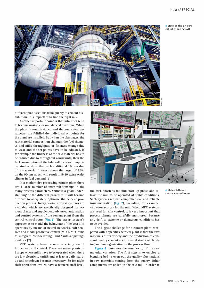
eration often needs only a little capital investment but issues such as operator training and fixed op-eration procedures are very important. If it comes to a de-bottlenecking of the plant or the upgrade/ modernization of single equipment usually mi-nor capital investments with a payback time of < 24 months are necessary. For an upgrade of the preheater, kiln and cooler system or new cement grinding equipment (Fig. 5) or new storage and dispatch facilities, major capital investments with 3-5 years payback can be feasible.
3 Process optimisation and production consistencyThe performance of a cement plant depends on a large number of parameters. An optimization of the plant’s throughput must not be the energy op-timum or vice versa. And there are a lot of other parameters, which could have their own optimum, such as the cement quality, maximum availability, maximum use of alternative fuels, lowest main-tenance or the environmental impact of the plant at the rated or other given capacity. Furthermore an individual optimization can be achieved for the
3 Advanced dry pyro-processing at Akcansa in Turkey
Hei
delb
ergC
emen
tJA
LIN
DIA
4 Benchmark 3 Mta Rewa cement plant in India
ZKG India Special 15
India // SPECIAL
5 State-of-the-art verti-cal roller mill (VRM)
Loes
che
different plant sections from quarry to cement dis-tribution. It is important to find the right mix.
Another important point is that kiln lines tend to become unstable or unbalanced over time. When the plant is commissioned and the guarantee pa-rameters are fulfilled the individual set points for the plant are installed. But when the plant ages, the raw material composition changes, the fuel chang-es and mills throughputs or fineness change due to wear and the set points have to be adjusted. If for example the fineness of the raw material has to be reduced due to throughput constraints, then the fuel consumption of the kiln will increase. Empiri-cal studies show that each additional 1 % residue of raw material fineness above the target of 12 % on the 90 µm screen will result in 5-10 extra kcal/t clinker in fuel demand [6].
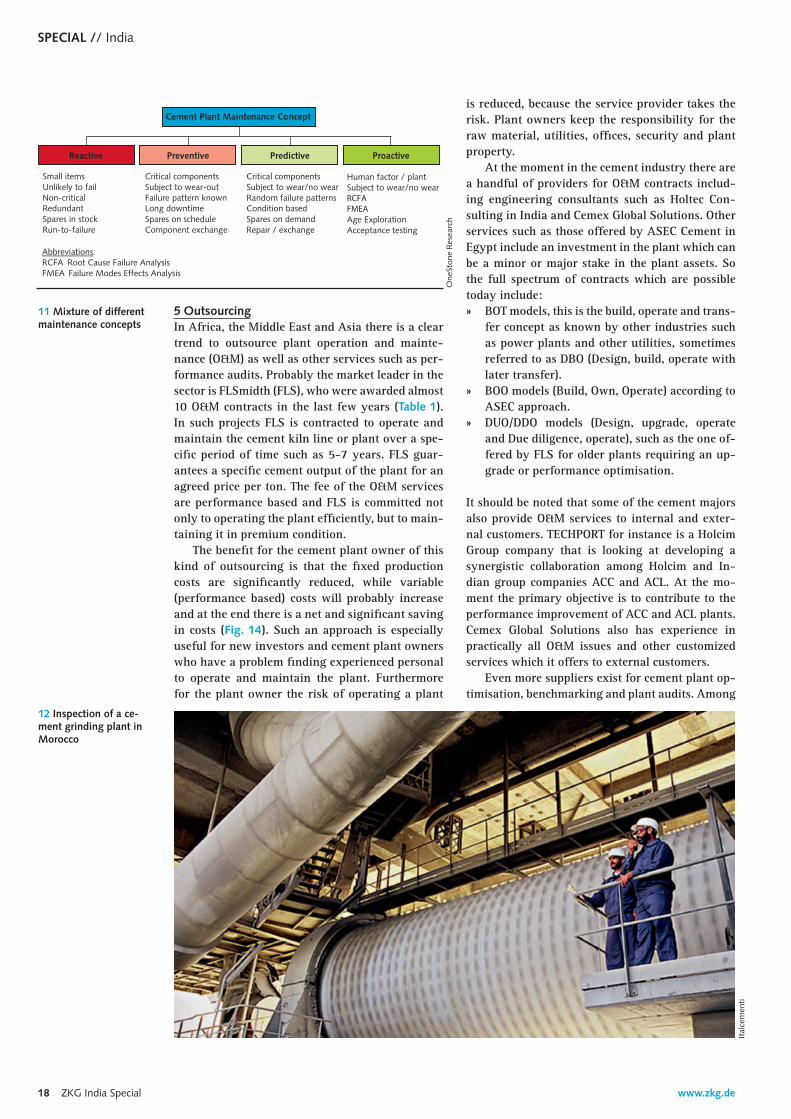
In a modern dry processing cement plant there are a large number of inter-relationships in the many process parameters. Without a good under-standing of the different processes it will become difficult to adequately optimize the cement pro-duction process. Today, various expert systems are available which are specifically designed for ce-ment plants and supplement advanced automation and control systems of the cement plant from the central control room (Fig. 6). The expert system’s approach is to model the behaviour of the best kiln operators by means of neural networks, soft sen-sors and model predictive control (MPC). MPC aims to integrate “self-learning” and “auto-adjusting” modules [7].
MPC systems have become especially useful for cement mill control. There are many plants in E urope where mills have to be operated when there are low electricity tariffs and at least a daily start-up and shutdown becomes necessary. So for night shift operations, which have a reduced staff level,
the MPC shortens the mill start-up phase and al-lows the mill to be operated at stable conditions. Such systems require comprehensive and reliable instrumentation (Fig. 7), including, for example, vibration sensors for the mill. When MPC systems are used for kiln control, it is very important that process alarms are carefully monitored, because any drift to extreme or dangerous conditions has to be avoided.
The biggest challenge for a cement plant com-pared with a specific chemical plant is that the raw materials differ widely and the production of con-stant quality cement needs several stages of blend-ing and homogenization in the process flow.
Figure 8 illustrates the complexity of the raw material variation. The first step is to employ a blending bed to even out the quality fluctuations in raw materials coming from the quarry. Other components are added in the raw mill in order to
6 State-of-the-art central control room
TKIS

www.zkg.de16 ZKG India Special
SPECIAL // India
attain the constant cement moduli for the burning process. Complete homogenization takes place in the raw meal blending silo.
The control system for the material handling starting with the receipt of raw material from the quarry to the kiln feed has to be designed to achieve the required level of material homogeneity. Figure 9 shows the qualitative result for the fluc-tuation in lime standard arising from the raw meal analysis method. The greatest range of fluctuation occurs in offline operation with manual sampling. In the case of inline operation with automatic sam-pling and automatic sample preparation there is only slight fluctuation that also depends on the number of samples per hour. More than two sam-ples per hour bring no further improvement [8].
The best means of achieving process optimiza-tion is generally a combination of online and inline analysis with two control loops. As depicted in Fig-ure 10, for the raw meal analysis the inner control loop is formed by an online analysis and the belt feed material is used as the manipulated variable.
The outer control loop consists of inline labora-tory analysis. Such a configuration can be used for the implementation of various cascade solutions, which can also include the raw meal blending silo to achieve an optimal raw meal consistency. How-ever, such methods also involve a significant in-crease in the amount of equipment and the com-plexity of the control system.
4 Maintenance strategiesIn a cement plant which is continuously operating not all components are necessarily running for 24 hours a day as is the case for the pyroprocessing equipment. There are some buffer functions, for example, in the raw material processing and clink-er storage, which allow the raw material handling system or the cement grinding system to be active for only 8 hours a day. Accordingly some cement plants have such high clinker storage and cement storage volumes that they can even produce and sell cements when the pyroprocessing line is in the annual shutdown.
So, “critical” equipment which is running around the clock needs different maintenance cri-teria than “non-critical” equipment which runs for 8 hours. In many cement plants the maintenance concept for the latter equipment is reactive or “as needed”, while for the critical equipment more proactive tools such as predictive and preventive maintenance are used. Figure 11 gives an idea of how the concept is applied to cement plants, with measures that can be installed in parallel, depend-ing on how critical the equipment is. The meas-ures adopted will depend on the cement producer’s philosophy, the age of the plant and budget con-straints.
Reactive or corrective maintenance allows the plant sections or components to operate until a fault or equipment failure occurs. These faults can usually be solved or repaired without requiring a plant stoppage. The situation is different in the case of critical components like large drive motors, large bearings for mills and gear units. To avoid the replacement of such components before they reach the end of their planned service life, the condition of the units is monitored. Condition monitoring can be implemented by recording different param-eters and interpreting them in order to assess the possibility of failure.
In recent years condition monitoring has experi-enced a real boom, due to the advance in automation solutions. Condition monitoring of plant compo-nents is supported by active maintenance concepts that are aimed at identifying fault mechanisms and consequential damage and determining the possible effects of, for example, operating errors or incorrect maintenance. One of the most widely established processes in the cement industry is computer-aided thermal imaging of rotary kilns. The latest processes
8 Blending and homogenisation of raw materials
TKIS
7 Condition monitoring of VRM mills
Siem
ens

ZKG India Special 17
India // SPECIAL
dustry. These systems are based on predictive and proactive tools and are a major part of the so-called reliability centred maintenance programs. CMMS use sophisticated failure mode and effect analy-sis (FMEA) and root cause failure analysis (RCFA) tools. So for example the RCFA is used to conduct an investigation into every kiln stoppage in order to find out and determine the true cause of failure and to prevent the same problem occurring in the future [9].
0
1
2
3
4
5
6
7
8
9
10
Offline 1/h Inline 1/h Inline 2/h Inline 4/h
LSF
(Sta
ndar
d D
evia
tion
)
9 Lime standard as a function of material analysis
One
Ston
e R
esea
rch
make use of infrared sensors that scan the entire length of the kiln and supply three-dimensional pic-tures and evaluations (Fig. 13).
Preventive maintenance is primarily employed for critical plant components that involve lengthy stoppages. It comprises a planned maintenance programme and regular inspections (Fig. 12) to en-sure high availability of the respective plant com-ponents. The inspection results determine whether the required maintenance can be carried out dur-ing the annual plant stoppage or need to be per-formed earlier. This particularly serves the purpose of avoiding expensive scheduled replacement of systems and equipment that are still in fully func-tional condition and have a lengthy residual ser-vice life expectation.
Preventive maintenance is essential to mini-mize the number of unplanned plant shutdowns. Shutdowns are always problematic because of the length of time involved and have a decisive effect on the cost-effectiveness of the plant. The mainte-nance concept is simple: solve problems before they happen. These requirements are met by inspecting critical plant components, such as the kiln, cooler, mills, large fans etc. to determine how smoothly the machines are running, whether vibrations or high surface temperatures occur, whether there is corro-sion etc., and by checking oil levels and lubricant conditions. Another purpose of regular inspections is to check that all plant safety issues are assured.
In the last few years computerized maintenance management systems (CMMS) have been more widely accepted and established in the cement in-
Customer Plant ountry Contract Status
ACC Ramliya I Egypt 2007 in productionAUCC Zliten Libya 07/2009 in productionFCK Sumbe Angola 04/2010 start-up 2014Jovein Cement Mashad Iran 05/2010 in productionWadi El Nile Wadi Egypt 05/2010 in productionNCC I & II Egypt 10/2010 in productionACC Ramliya II Egypt 05/2011 in productionCarthage Cement Djebel Ressas Tunesia 10/2012 in productionDangote Cement 5 lines Nigeria 11/2013 start-up 2014
Tab. 1 O&M contracts
10 Process optimisa-tion with online/inline control loop
FLSm
idth
FLSm
idth
, One
Ston
e R
esea
rch
www.zkg.de18 ZKG India Special
SPECIAL // India
12 Inspection of a ce-ment grinding plant in Morocco
Ital
cem
enti
Cement Plant Maintenance Concept
Reactive Preventive Predictive Proactive
Small itemsUnlikely to failNon-critical RedundantSpares in stockRun-to-failure
Critical componentsSubject to wear-outFailure pattern knownLong downtimeSpares on scheduleComponent exchange
Critical componentsSubject to wear/no wearRandom failure patternsCondition based Spares on demandRepair / exchange
Human factor / plantSubject to wear/no wearRCFAFMEAAge ExplorationAcceptance testing
Abbreviations:RCFA Root Cause Failure AnalysisFMEA Failure Modes Effects Analysis
11 Mixture of different maintenance concepts
One
Ston
e R
esea
rch
5 OutsourcingIn Africa, the Middle East and Asia there is a clear trend to outsource plant operation and mainte-nance (O&M) as well as other services such as per-formance audits. Probably the market leader in the sector is FLSmidth (FLS), who were awarded almost 10 O&M contracts in the last few years (Table 1). In such projects FLS is contracted to operate and maintain the cement kiln line or plant over a spe-cific period of time such as 5-7 years. FLS guar-antees a specific cement output of the plant for an agreed price per ton. The fee of the O&M services are performance based and FLS is committed not only to operating the plant efficiently, but to main-taining it in premium condition.
The benefit for the cement plant owner of this kind of outsourcing is that the fixed production costs are significantly reduced, while variable (performance based) costs will probably increase and at the end there is a net and significant saving in costs (Fig. 14). Such an approach is especially useful for new investors and cement plant owners who have a problem finding experienced personal to operate and maintain the plant. Furthermore for the plant owner the risk of operating a plant
is reduced, because the service provider takes the risk. Plant owners keep the responsibility for the raw material, utilities, offices, security and plant property.
At the moment in the cement industry there are a handful of providers for O&M contracts includ-ing engineering consultants such as Holtec Con-sulting in India and Cemex Global Solutions. Other services such as those offered by ASEC Cement in Egypt include an investment in the plant which can be a minor or major stake in the plant assets. So the full spectrum of contracts which are possible today include: » BOT models, this is the build, operate and trans-
fer concept as known by other industries such as power plants and other utilities, sometimes referred to as DBO (Design, build, operate with later transfer).
» BOO models (Build, Own, Operate) according to ASEC approach.
» DUO/DDO models (Design, upgrade, operate and Due diligence, operate), such as the one of-fered by FLS for older plants requiring an up-grade or performance optimisation.
It should be noted that some of the cement majors also provide O&M services to internal and exter-nal customers. TECHPORT for instance is a Holcim Group company that is looking at developing a synergistic collaboration among Holcim and In-dian group companies ACC and ACL. At the mo-ment the primary objective is to contribute to the performance improvement of ACC and ACL plants. C emex Global Solutions also has experience in practically all O&M issues and other customized services which it offers to external customers.
Even more suppliers exist for cement plant op-timisation, benchmarking and plant audits. Among

ZKG India Special 19
India // SPECIAL
cash-flow fixed industry. Accordingly it is forecast that the trends will continue in this decade and might even accelerate in the next decade. On the other hand more service providers will enter the market and the services will become more competi-tive while margins shrink.
the leading engineering consultants are Holtec Consulting, PEC Consulting, PEG Engineering, Penta Engineering, JAMCEM Consulting, CemCon AG, Cement Performance International (CPI) and Whitehopleman as well as the major equipment suppliers and equipment specialists such as FLS-midth, Thyssen Krupp Industrial Solutions, KHD Humbold Wedag, Siemens and ABB to name a few.
The concepts for plant optimization of the dif-ferent suppliers seem to be very similar, although the tools may differ significantly. Such an opti-misation always starts with a plant audit to get an independent assessment of the plant condition, identifying bottlenecks [10, 11]. In a second step opportunities for improvement are derived from benchmarking methods. In the final step a report is prepared in which measures are outlined as to how the gap can be closed and how the opportunities can be taken advantage of.
Other services that are offered include: » Energy optimisation » Product quality enhancement » Remote plant operations & efficiency monitor-
ing » Capacity balancing & enhancement » Productivity improvements
6 OutlookThe cement services sector generates higher mar-gins for suppliers than the equipment supply sec-tor. This was true in the past and will probably continue to be true in the future. Suppliers like FLSmidth already generate higher revenues in the cement business from cement services than from equipment supply. At the moment, especially, the demand for outsourcing is fast growing due to the needs of larger cement plants for adequate perfor-mance management and reduced personal in the plants.
With O&M services from third parties, cement plant owners are able to reduce their fixed costs which today become more and more important in a
13 Display of a kiln scanning system
HG
H S
yste
ms
Infr
arou
ges
14 Financial benefits of O&M outsourcing FL
Smid
th
REFERENCES
[1] Harder, J.: Current Modernisation and Maintenance Concepts in the Cement Industry. ZKG International, 5/2010, pp. 24-38[2] CIPEC: Energy Performance Benchmarking and Best Practices in Canadian Cement Manufacturing Sector. Canadian Industry Program
for Energy Conservation (CIPEC). ISBN 978-1-100-14036-0, Ottawa, Ontario/Canada 2009[3] Harder, J.: Trends in Cement Kiln Pyroprocessing. ZKG International, 2/2012, pp. 22-32[4] Aebischer. T.: Performance Measurement at Holcim, Presentation at Swiss CFO Day 2014, 22.01.2014, Zug/Switzerland[5] Harder, J.: Trends in Kiln Systems for the Cement Industry. ZKG International, 7/2007, pp. 38-49[6] Mutter, M.: Finding the Balance. World Cement, March 2012, pp. 73-76[7] Alsop, P.A.: The Cement Plant Operations Handbook – The Concise Guide to Cement Manufacture. Sixth Edition January 2014. Trade-
ship Publications Ltd., Dorking, Surrey/UK.[8] Harder, J.: Material Analysis for Process Control in Cement Plants. ZKG International, 7-6-7/2009, pp. 58-71[9] Mutter, M.: Managing for Reliability. World Cement, September 2013, pp. 95-98[10] Boon, B.: All about Audits, World Cement, September 2010, pp 139-141[11] Rudd, K.: Mechanical Integrity and Reliability, World Cement, September 2013, pp. 91-94

www.zkg.de20 ZKG India Special
quality-monitored and tailor-made for existing kilns or newly-installed kilns and its chemistry of geological survey and products.
For example in Germany the ban on landfill in 2005 pushed the development of technologies for co-processing in the electricity and cement in-dustry. Based on 30 years of proven experience, co-processing is assuming an important role for integrated waste and energy concepts, however in that reduction target on emission of greenhouse gases (GHG).
1 IntroductionTo cut the energy cost for clinker production, the German cement industry started substitution of primary fuels with Alternative Fuels (AF) such as used oil or tyres after the first oil shock in the early 1970s. Today, at more than 2 €/GJ energy costs and after establishing a reliable disposal management, alternative fuels and raw materials (AFR) include a wide range of types of hazardous and non-hazard-ous waste, as well as solid and liquid, organic and mineral waste, which have to be pre-processed,
SPECIAL AFR
Proven experience with alternative fuels in the cement kiln process
TEXT Dr. Hubert Baier, ZKG International, Gütersloh/Germany
In times of increasing energy costs, it is of vital interest for any company to save energy.
To cut the energy costs for clinker production, the German cement industry started substitution
of primary fuels with Alternative Fuels (AF) such as used oil or tyres after the first oil crisis
of 1973. Today, alternative fuels and raw materials (AFR) include a wide range of types of
Co-processing of SRF
hazardous and non-hazardous waste, as well as solid and liquid, organic and mineral waste.
SPECIAL // India
ZKG India Special 21
India // SPECIAL
Therefore almost 50 Mechanical-Biological Treatment (MBT) public plants were installed with an annual input of approx. 6 million tons of mu-nicipal solid waste (MSW) and hundreds of small, privately owned plants preselect feasible com-mercial & industrial waste (C&IW), which have to be subsequently processed into tailor-made residue derived fuels (RDF, < 80 mm) for calciners and quality-monitored solid recovered fuel (SRF, < 25 mm) for main burners.
Realizing in some cases ~100 % thermal sub-stitution rates (TSR), the German cement indus-try reached a high level of more than 60 % of its thermal demand of about 92 million GJ, which correspond totally with approx. 2 million tons of alternative fuels. Solid, liquid or pasty from haz-ardous or non-hazardous sources, the feedstock for alternative fuels is different like tyres, meat & bone meal, waste oil or solvents, or production residues (textiles, paper, wrappings, cuts etc.) and biomass have to be pre-treated to meet the requirements regarding handling, dosage, feeding, combustion, process, air pollution and product performance.
The article will focus on the main aspects of pre-processing of waste and co-processing of AF in ce-ment kilns, by identification, waste management, pre-treating and utilization in the cement clinker process with sophisticated processing techniques.
The process of clinker burning has to be as-sessed with regard to its technical options and de-faults. The pre-processing and handling concept within the cement plant as well as the impact of AF on the manufacturing process will be emphasised. Of major importance in this context are pyropro-cessing as well as combustion at its point of en-trance, impact on product and emission.
2 Initial positionsDue to the continuing energy cost fluctuations and the discussions on the sustainable protection of re-sources, the German cement industry was able to achieve a continual reduction of its entire power requirement by changing from the wet process to the dry process inclusive preheater tower.
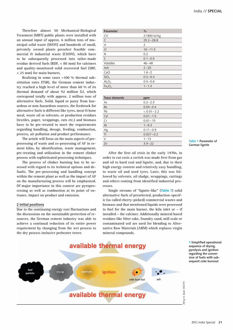
After the first oil crisis in the early 1970s, in order to cut costs a switch was made first from gas and oil to hard coal and lignite, and, due to their high energy content and relatively easy handling, to waste oil and used tyres. Later, this was fol-lowed by solvents, oil sludge, wrappings, cuttings and others coming from identified industrial pro-cesses.
Single streams of “lignite-like” (Table 1) solid alternative fuels of preselected, production-specif-ic (so called cherry-picked) commercial wastes and biomass and that mentioned liquids were processed to fuel for the main burner, the kiln inlet or – if installed – the calciner. Additionally mineral based residues like filter cake, foundry sand, mill scale or contaminated soil are used for blending to Alter-native Raw Materials (ARM) which replaces virgin mineral compounds.
1 Simplified operational sequence of drying, pyrolysis and ignition regarding the conver-sion of fuels with sub-sequent coke burnout
All
by H
. Bai
er (
WLT
P)
Parameter %
CV 21 800 kJ/kgC 25.2 – 28.8H 2O 10 – 11.5N 0.2S 0.1 – 0.5Volatiles 46 – 48Ash 2 – 20CaO 1.6 – 2SiO2 0.3 – 0.4Al2O3 0.5 – 0.6Fe2O3 1 – 1.4
Trace elements ppm
As 0.2 – 2.5Be 0.04 – 0.4Pb < 0.01 – 2.2Cd 0.01 – 1.5Cr 0.01 – 15Ni 1 – 9.3Hg 0.11 – 0.9Tl 0.027 – 0.2V 1 – 13Zn 3.9 – 22
Table 1 Parameter of German lignite

www.zkg.de22 ZKG India Special
SPECIAL // India
Since it was proved that the use of individually processed wastes had no effect on the emission bal-ance of the plant or on the clinker burning process or the product quality, the wastes may now also be manufactured as blends and used for the energy content as well as the ash content to create clinker, shortly co-processing.
In the meantime, the alternative fuel produc-tion and use have been established to the point that especially countries, which are extremely depend-ent on external energy resources increasingly take into account the integration of waste management into a country-wide energy concept to avoid high public investments into large sanitary landfillings
or stand-alone municipal waste incinerators. In or-der to implement such concepts, naturally also ce-ment plants come into focus. Frequently, however, this makes us forget that cement is a standardised mass product of a highly energy-efficient produc-tion process.
The general opinion is that “alternative fuel” still implies cheap “disposal” to the extent that even legislation talks about “co-combustion”. But actually, these are highly complex physical-chem-ical conversion processes, which have not yet been entirely clarified even with regard to the combus-tion of coal.
Simplifying combustion as a diffusion con-trolled combustion process (Fig. 1) it can be de-scribed as drying, pyrolysis, ignition and coke burnout in a decreasing oxygen atmosphere. With an increasing TSR, this sequence dominates the combustion and in consequent the entire cement-clinker process.
Usually, commercial wastes and fractions of high calorific value are separately or jointly pre-processed while removing water, metals, glass, ash or other harmful constituents from the fuel.
Therefore, solid alternative fuels with an aver-age lump size of dmax. 300 mm to be fed via kiln inlet or a calciner to the rotary kiln are subject to a different sample preparation procedure and quality management than those fuels, which must be fed via main burner. For a better burnout, these compounds must be comminuted into pieces (dmax. 25 mm or finer) and sifted to avoid reductive burning conditions in the kiln’s sinter zone and still coming to several powers of ten compared to coal dust. If the processing should be finer still, the processing increasingly reaches technical and economic limits.
Normally, in the cement plant, ready to be burnt fuels are transported pneumatically to the respective firing point. Especially, if they are fed via the main burner, the recent inhomogeneous alternative fuel mixtures are differentiated again into individual particle fractions burning at dif-ferent levels: While thin, large-area particles (e.g.
2 Clinker as an inter-mediate product ofcement production. Right: under normalconditions, left: burnt under reductive conditions, bottom: reductively burnt with a so-called “brown core”
3 Sifted SRF (<30mm) matching the requirements for combustion in a sinter zone burner
Table 2 Average param-eter of SRF (preselected industrial waste com-ponents)
Parameter %
CV 21 800 – 32 200 kJ/kgC1 n.d.H n.d.O n.d.N n.d.S 0.1 – 0.8Volatiles n.d.Ash 9 – 39CaO n.d.SiO2 n.d.Al2O3 n.d.Fe2O3 n.d.Cl 0.39 – 2.2F 0.1 – 1.7
1 The distinction between the share of biogenic carbon and fossil carbon is important for the GHG approval.
Trace elements ppm
As 0.68 – 15.32Pb 27 – 4.406Cd 0.75 – 162Cr 19.10 – 187Ni 5.41 – 1.622Hg 0.09 – 1.62Tl 0.23 – 1.96V 2.17 – 164
ZKG India Special 23
India // SPECIAL
30.0
25.0
20.0
15.0
10.0
5.0
0.0
0.45
0.4
0.35
0.3
0.25
0.2
0.15
0.1
0.05
0<1.5 1.5 2 3 4 5 6 7 8 9
rate of descent m/s
Mas
s w
t.–%
Dic
hte
t/m
3
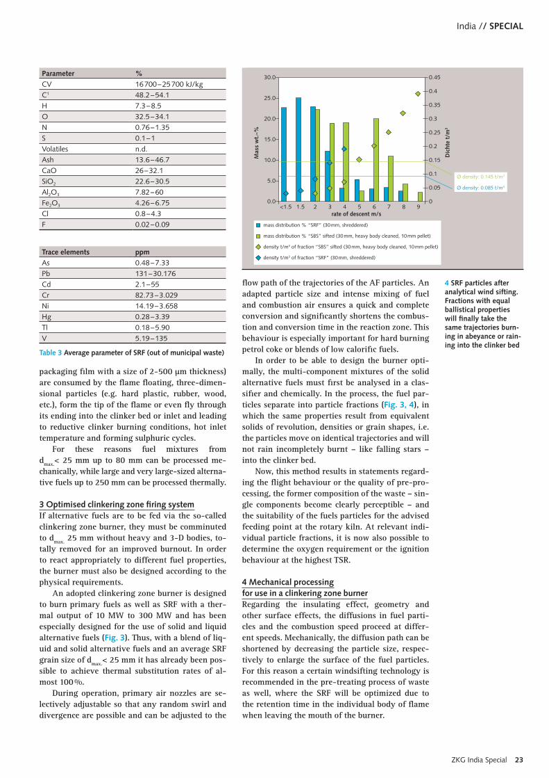
mass distribution % “SRF” (30 mm, shreddered)
mass distribution % “SBS” sifted (30 mm, heavy body cleaned, 10 mm pellet)
density t/m3 of fraction “SBS” sifted (30 mm, heavy body cleaned, 10 mm pellet)
density t/m3 of fraction “SRF” (30 mm, shreddered)
Ø density: 0.145 t/m3
Ø density: 0.085 t/m3
4 SRF particles after analytical wind sifting. Fractions with equal ballistical properties will finally take the same trajectories burn-ing in abeyance or rain-ing into the clinker bed
packaging film with a size of 2-500 µm thickness) are consumed by the flame floating, three-dimen-sional particles (e.g. hard plastic, rubber, wood, etc.), form the tip of the flame or even fly through its ending into the clinker bed or inlet and leading to reductive clinker burning conditions, hot inlet temperature and forming sulphuric cycles.
For these reasons fuel mixtures from dmax.< 25 mm up to 80 mm can be processed me-chanically, while large and very large-sized alterna-tive fuels up to 250 mm can be processed thermally.
3 Optimised clinkering zone firing systemIf alternative fuels are to be fed via the so-called clinkering zone burner, they must be comminuted to dmax. 25 mm without heavy and 3-D bodies, to-tally removed for an improved burnout. In order to react appropriately to different fuel properties, the burner must also be designed according to the physical requirements.
An adopted clinkering zone burner is designed to burn primary fuels as well as SRF with a ther-mal output of 10 MW to 300 MW and has been especially designed for the use of solid and liquid alternative fuels (Fig. 3). Thus, with a blend of liq-uid and solid alternative fuels and an average SRF grain size of dmax.< 25 mm it has already been pos-sible to achieve thermal substitution rates of al-most 100 %.
During operation, primary air nozzles are se-lectively adjustable so that any random swirl and divergence are possible and can be adjusted to the
flow path of the trajectories of the AF particles. An adapted particle size and intense mixing of fuel and combustion air ensures a quick and complete conversion and significantly shortens the combus-tion and conversion time in the reaction zone. This behaviour is especially important for hard burning petrol coke or blends of low calorific fuels.
In order to be able to design the burner opti-mally, the multi-component mixtures of the solid alternative fuels must first be analysed in a clas-sifier and chemically. In the process, the fuel par-ticles separate into particle fractions (Fig. 3, 4), in which the same properties result from equivalent solids of revolution, densities or grain shapes, i.e. the particles move on identical trajectories and will not rain incompletely burnt – like falling stars – into the clinker bed.
Now, this method results in statements regard-ing the flight behaviour or the quality of pre-pro-cessing, the former composition of the waste – sin-gle components become clearly perceptible – and the suitability of the fuels particles for the advised feeding point at the rotary kiln. At relevant indi-vidual particle fractions, it is now also possible to determine the oxygen requirement or the ignition behaviour at the highest TSR.
4 Mechanical processing for use in a clinkering zone burnerRegarding the insulating effect, geometry and other surface effects, the diffusions in fuel parti-cles and the combustion speed proceed at differ-ent speeds. Mechanically, the diffusion path can be shortened by decreasing the particle size, respec-tively to enlarge the surface of the fuel particles. For this reason a certain windsifting technology is recommended in the pre-treating process of waste as well, where the SRF will be optimized due to the retention time in the individual body of flame when leaving the mouth of the burner.
Table 3 Average parameter of SRF (out of municipal waste)
Parameter %
CV 16 700 – 25 700 kJ/kgC1 48.2 – 54.1H 7.3 – 8.5O 32.5 – 34.1N 0.76 – 1.35S 0.1 – 1Volatiles n.d.Ash 13.6 – 46.7CaO 26 – 32.1SiO2 22.6 – 30.5Al2O3 7.82 – 60Fe2O3 4.26 – 6.75Cl 0.8 – 4.3F 0.02 – 0.09
Trace elements ppm
As 0.48 – 7.33Pb 131 – 30.176Cd 2.1 – 55Cr 82.73 – 3.029Ni 14.19 – 3.658Hg 0.28 – 3.39Tl 0.18 – 5.90V 5.19 – 135

www.zkg.de24 ZKG India Special
This process is perfectly applicable to particles, which are three-dimensional, hard or brittle and so far have led to reductive burning conditions in kiln material. They are separated quickly and effective-ly, whereby large, but thin two-dimensional flat particles are mostly obtained, which do not affect the combustion with regard to the burnout behav-iour. While the amount of heavy, water containing and three-dimensional particles are reduced, the chemical properties of the alternative fuel compo-nents remain unchanged.
5 Use of alternative fuels at the calcinerIn modern plants with calciners only 40 % of the thermal output is covered by the clinkering zone burner, while 60 % of the thermal heat demand is covered by one or more firing points at the calciner. In the process, the necessary combustion air is fed via the tertiary air duct from the recuperation sec-
tion of the clinker cooler to the firing points inside the calciner. With regard to reaction, the calciner requires only a temperature of 850-900°C to cal-cinate the limestone fraction. Inside the calciner, the 1000-1200°C hot flue gases of the rotary kiln and the 800-1000°C hot tertiary air mix, whereby safe ignition and burning are also ensured by slow-reacting, large-sized alternative fuels.
However, especially the burning of various and slow-reacting fuels takes significantly longer time than the preheating and calcining of the raw meal and is consequently the determining factor for the calciner’s dimension. For this reason, various tech-nical solutions for calciners are available. These will allow a control of the combustion temperature and atmosphere so that it is also possible to reduce the NOx emissions.
In order to ensure the burnout of slow-reacting alternative or primary fuels it is not only necessary to support the retension time inside the calciner with a suitable distance required for calcination and burnout but if necessary, by using an addi-tional burning chamber.
For coarse fuels with a very long retention time (Fig. 5), such as biomass, petroleum coke or anthracite, the precombustion chamber is used, where in the centre of a vortex flow and with an initial supply of pure tertiary air high tempera-tures develop starting drying, pyroprocessing, ig-
5 RDF (< 80 mm) for the calciner requires a long retention time
Table 4 Indication for input criteria of AFR for valorization in a dry system with preheater and calciner
Element Concentration
CaO in ash
single or in total > 50 wt.-%
SiO2 in ashAl2O3 in ashFe2O3 in ashMercury (Hg) < 2 ppm dry substanceCadmium (Cd) < 50 ppm dry substanceThallium (Tl) < 45 ppm dry substanceother trace elements < 20 000 ppm dry substance

ZKG India Special 25
India // SPECIAL
REFERENCES
[1] Baier, H. (2006): Ersatzbrennstoffe für den Einsatz in Mitverbrennungsanlagen (Alternative fuels to be used in co-combustion), in Zement-Kalk-Gips International, Bauverlag BV Springer BauMedien Gütersloh, No. 3-2006, Volume 59, pp. 78–85
[2] Baier, H. (2009): Erzeugung von Ersatzbrennstoffen für die deutsche Zementindustrie – Rahmenbedingungen, Herkunft, Aufwand und Realisierung- (Production of second-ary fuels for the German cement industry – Basic conditions, origin, expense and implementation), Berliner Energiekonferenz Erneuerbare Energien (Energy Conference Renewable Energies in Berlin) 10./11. November 2009 in Berlin, TK Publishing House Neuruppin 2009, pp. 75–88
[3] Baier, H. (2010): Disruptive substances and the burning behavior of solid alternative fuels, in Zement-Kalk-Gips International, Bauverlag BV Springer BauMedien Güters-loh, No. 6-2010, Volume 63, pp. 58–67
[4] FLSmidth – One Source product prospectuous: HOTDISCTM combustion device[5] Mass, U., Frie, Sebastian (2013): Proceedings -Special Lectures and Extended Ab-
stracts, 13th NCB International Seminar on Cement Building Materials 19–22 Novem-ber 2013, New Delhi, India, p. 175ff, published by National Council for Cement and Building Materials 34km Stone, Delhi-Mathura Road (NH-2), Ballabgarh 121004, Haryana/India
[6] Menzel, K., Maas, U., Lampe, K. (2009) Technologies for Alternative Fuel Enhance-ment in Clinker Production Lines, 2009 IEEE Cement Industry Technical Conference Record
[7] N.N. (2005): Leitfaden zur energetischen Verwertung von Abfällen in Zement-, Kalk- und Kraftwerken in Nordrhein-Westfalen (Guideline for thermal valorization of waste in cement and lime works, power plants in Northrhine-Westphalia), 2. Circulation, Ministry of Environment and Conservation of Nature, Agriculture and Consumer Protection of Northrhine-Westphalia
[8] Reznichenko, A. (2009): Welcome to a new dimension, Burner Technology, Interna-tional Cement Review, Tradeship Publications Ltd. Dorking, June 2009, pp. 96–98
Kiln Shell Thermal
Monitoring
nition and burnout. For the use of low calorific, large-sized alternative fuels the retention time in the short hot zone is insufficient. Therefore, a precombustion chamber has been especially developed for the high feed rate of low calorific, large-sized alternative fuels.
The typical retention time of 4-8 sec-onds in a calciner is sometimes grossly insufficient for the safe burnout of such slow-reacting alternative f uels like high calorific fraction (HCF) with a diameter approx. < 300 mm. Therefore, FLSmidth developed its “Hot Disk” as a turning ta-ble integrated with the preheater and cal-ciner systems. It has proven its feasibility for coarse alternative mono fraction fuels made as for truck tires or biomass in sizes up to approx. one metre in diameter.
ThyssenKrupp Industrial Solution de-veloped its “Step Combustor” also added on to the calciner but capable of burning different alternative fuel qualities be-cause the transport and discharge rates are separately controlled by air blast nozzles and no mechanical internal fit-tings are necessary inside to push over the edge into calciner.

www.zkg.de26 ZKG India Special
The intention of the Basel Convention, ratified in 1989, is to control shipment of hazardous wastes across borders, to avoid dumping in developing countries and to stimulate local treatment.
Environmentally sound disposal of hazardous chemicals and POPs is however costly and compli-cated, and export may not be affordable to many developing countries. In contrast to incinerators and other treatment techniques, cement kilns al-ready exist in virtually every country and resorting to them may be feasible and cost-efficient for the treatment of POPs wastes and other types of haz-ardous wastes.
2 Cement kilns“Co-processing” of alternative fuels and resources in the cement industry should primarily be about energy recovery and material recycling. In special cases however, where hazardous chemicals are posing an imminent threat to health and environ-
1 IntroductionSeveral international conventions aim to protect human health and the environment by requir-ing parties to take measures to reduce or elimi-nate releases of hazardous chemicals like obso-lete pesticides and persistent organic pollutants (POPs) from intentional production and use, from stockpiles and wastes and from unintentional re-lease. The Aarhus Protocol covers 16 POPs and the Stockholm Convention on POPs covers for the time being 21 compounds or groups of com-pounds.
There is currently no reliable information available regarding what quantities these POPs constitute on a global level but these conventions acknowledge that there is an urgent need for en-vironmentally sound disposal and that developing countries and countries with economies in transi-tion need to strengthen their national capabilities on sound management of hazardous chemicals.
SINTEF
Destruction of hazardous chemicals and POPs in cement kilns
TEXT Dr. Kåre Helge Karstensen, Chief Scientist, Foundation for Scientific and Industrial Research – SINTEF, Oslo/Norway
Hazardous chemicals and persistent organic pollutants constitute a threat to health
and environment, both locally and globally. Many developing countries have no destruction
options available and export is usually too costly. Cement kilns can be found in virtually
every country and might constitute a sound treatment option if found feasible.
Inspection tour along the kiln during the test run
SIN
TEF
ZKG India Special 27
India // SPECIAL
ment and where no other disposal option exist, the feasibility of using a local cement kiln for destruc-tion could be investigated.
A BAT/BEP cement kiln has many inherent fea-tures which makes it ideal for organic hazardous waste treatment: high temperatures, long residence time, surplus oxygen during and after combustion, good turbulence and mixing conditions, thermal buffer capacity, dry scrubbing of the exit gas by alkaline raw material (neutralises acid gases like hydrogen chloride), fixation of traces of heavy met-als in the clinker structure, no production of by-products such as slag, ashes or liquid residues and complete recovery of energy and raw material com-ponents in the waste (Karstensen, 1998 and 2006).
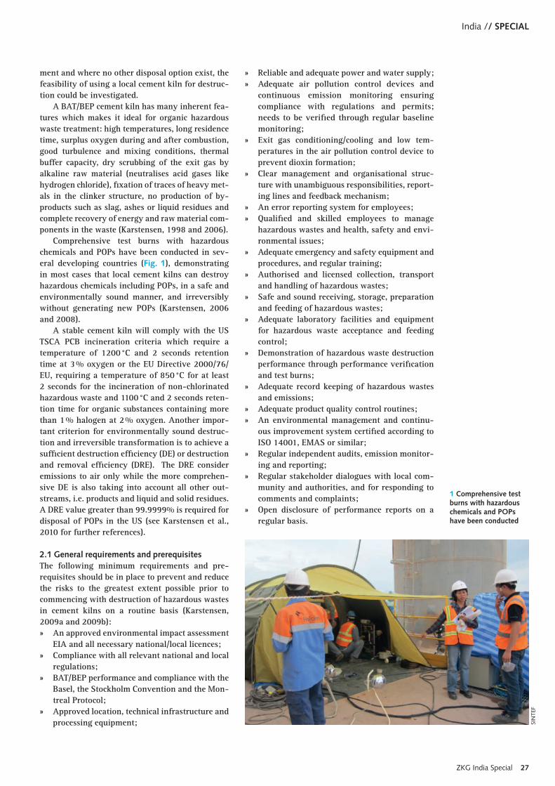
Comprehensive test burns with hazardous chemicals and POPs have been conducted in sev-eral developing countries (Fig. 1), demonstrating in most cases that local cement kilns can destroy hazardous chemicals including POPs, in a safe and environmentally sound manner, and irreversibly without generating new POPs (Karstensen, 2006 and 2008).
A stable cement kiln will comply with the US TSCA PCB incineration criteria which require a temperature of 1200 °C and 2 seconds retention time at 3 % oxygen or the EU Directive 2000/76/EU, requiring a temperature of 850 °C for at least 2 seconds for the incineration of non-chlorinated hazardous waste and 1100 °C and 2 seconds reten-tion time for organic substances containing more than 1 % halogen at 2 % oxygen. Another impor-tant criterion for environmentally sound destruc-tion and irreversible transformation is to achieve a sufficient destruction efficiency (DE) or destruction and removal efficiency (DRE). The DRE consider emissions to air only while the more comprehen-sive DE is also taking into account all other out-streams, i.e. products and liquid and solid residues. A DRE value greater than 99.9999% is required for disposal of POPs in the US (see Karstensen et al., 2010 for further references).
2.1 General requirements and prerequisitesThe following minimum requirements and pre-requisites should be in place to prevent and reduce the risks to the greatest extent possible prior to commencing with destruction of hazardous wastes in cement kilns on a routine basis (Karstensen, 2009a and 2009b): » An approved environmental impact assessment
EIA and all necessary national/local licences; » Compliance with all relevant national and local
regulations; » BAT/BEP performance and compliance with the
Basel, the Stockholm Convention and the Mon-treal Protocol;
» Approved location, technical infrastructure and processing equipment;
» Reliable and adequate power and water supply; » Adequate air pollution control devices and
continuous emission monitoring ensuring compliance with regulations and permits; needs to be verified through regular baseline monitoring;
» Exit gas conditioning/cooling and low tem-peratures in the air pollution control device to prevent dioxin formation;
» Clear management and organisational struc-ture with unambiguous responsibilities, report-ing lines and feedback mechanism;
» An error reporting system for employees; » Qualified and skilled employees to manage
hazardous wastes and health, safety and envi-ronmental issues;
» Adequate emergency and safety equipment and procedures, and regular training;
» Authorised and licensed collection, transport and handling of hazardous wastes;
» Safe and sound receiving, storage, preparation and feeding of hazardous wastes;
» Adequate laboratory facilities and equipment for hazardous waste acceptance and feeding control;
» Demonstration of hazardous waste destruction performance through performance verification and test burns;
» Adequate record keeping of hazardous wastes and emissions;
» Adequate product quality control routines; » An environmental management and continu-
ous improvement system certified according to ISO 14001, EMAS or similar;
» Regular independent audits, emission monitor-ing and reporting;
» Regular stakeholder dialogues with local com-munity and authorities, and for responding to comments and complaints;
» Open disclosure of performance reports on a regular basis.
1 Comprehensive test burns with hazardous chemicals and POPs have been conducted
SIN
TEF
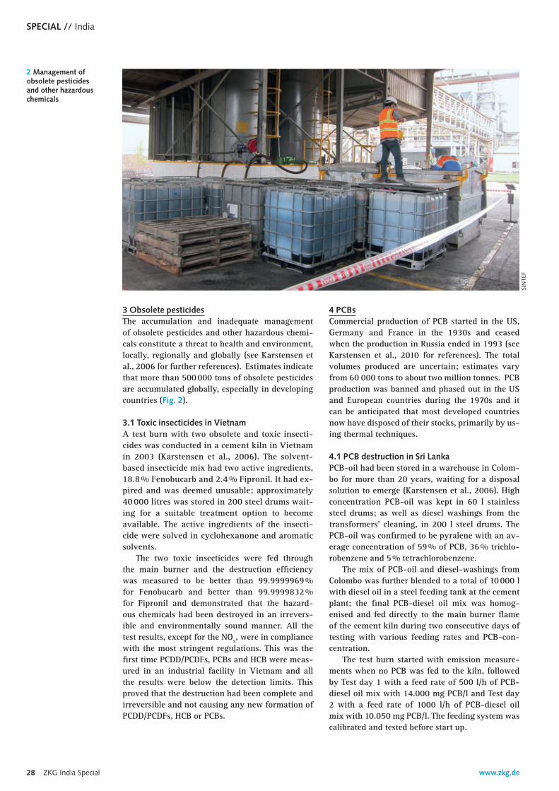
www.zkg.de28 ZKG India Special
SPECIAL // India
3 Obsolete pesticidesThe accumulation and inadequate management of obsolete pesticides and other hazardous chemi-cals constitute a threat to health and environment, locally, regionally and globally (see Karstensen et al., 2006 for further references). Estimates indicate that more than 500 000 tons of obsolete pesticides are accumulated globally, especially in developing countries (Fig. 2).
3.1 Toxic insecticides in VietnamA test burn with two obsolete and toxic insecti-cides was conducted in a cement kiln in Vietnam in 2003 (Karstensen et al., 2006). The solvent-based insecticide mix had two active ingredients, 18.8 % Fenobucarb and 2.4 % Fipronil. It had ex-pired and was deemed unusable; approximately 40 000 litres was stored in 200 steel drums wait-ing for a suitable treatment option to become available. The active ingredients of the insecti-cide were solved in cyclohexanone and aromatic solvents.
The two toxic insecticides were fed through the main burner and the destruction efficiency was measured to be better than 99.9999969 % for Fenobucarb and better than 99.9999832 % for Fipronil and demonstrated that the hazard-ous chemicals had been destroyed in an irrevers-ible and environmentally sound manner. All the test results, except for the NOx, were in compliance with the most stringent regulations. This was the first time PCDD/PCDFs, PCBs and HCB were meas-ured in an industrial facility in Vietnam and all the results were below the detection limits. This proved that the destruction had been complete and irreversible and not causing any new formation of PCDD/PCDFs, HCB or PCBs.
4 PCBsCommercial production of PCB started in the US, Germany and France in the 1930s and ceased when the production in Russia ended in 1993 (see Karstensen et al., 2010 for references). The total volumes produced are uncertain; estimates vary from 60 000 tons to about two million tonnes. PCB production was banned and phased out in the US and European countries during the 1970s and it can be anticipated that most developed countries now have disposed of their stocks, primarily by us-ing thermal techniques.
4.1 PCB destruction in Sri LankaPCB-oil had been stored in a warehouse in Colom-bo for more than 20 years, waiting for a disposal solution to emerge (Karstensen et al., 2006). High concentration PCB-oil was kept in 60 l stainless steel drums; as well as diesel washings from the transformers’ cleaning, in 200 l steel drums. The PCB-oil was confirmed to be pyralene with an av-erage concentration of 59 % of PCB, 36 % trichlo-robenzene and 5 % tetrachlorobenzene.
The mix of PCB-oil and diesel-washings from Colombo was further blended to a total of 10 000 l with diesel oil in a steel feeding tank at the cement plant; the final PCB-diesel oil mix was homog-enised and fed directly to the main burner flame of the cement kiln during two consecutive days of testing with various feeding rates and PCB-con-centration.
The test burn started with emission measure-ments when no PCB was fed to the kiln, followed by Test day 1 with a feed rate of 500 l/h of PCB-diesel oil mix with 14.000 mg PCB/l and Test day 2 with a feed rate of 1000 l/h of PCB-diesel oil mix with 10.050 mg PCB/l. The feeding system was calibrated and tested before start up.
2 Management of obsolete pesticides and other hazardous chemicals
SIN
TEF

ZKG India Special 29
India // SPECIAL
The three-day test burn demonstrated that it was able to destroy PCBs in an irreversible and en-vironmentally sound manner without causing any new formation of PCDD/PCDF or HCB (Karstensen et al., 2010). The destruction and removal efficien-cy was better than 99.9999 % at the highest PCB feeding rate.
4.2 PCB destruction in El SalvadorA test burn with TCE and PCBs was carried out in El Salvador in 2007 and 2009; the DRE was meas-ured to be better than six nines in both cases, i.e. > 99.9999 %. We could not detect any influence on the emissions of PCDD/PCDFs; the average concen-tration measured during in total seven days was 0.0398 ng I-TEQ/m3.
4.3 PCB destruction in VietnamHigh strength PCB was transported to the Hon Chong cement plant in South Vietnam in steel drums and diluted in two 16 000 l feeding tanks, making two batches for two days testing (Fig. 3). The entire test campaign was carried out over three days; the first day a baseline test was performed, i.e. with stack gas sampling under normal condi-tions with coal firing only and with the exit gas through the raw mill in compound mode – the next two days, a mix of PCB and used oil was fed to the main burner of the kiln; only the first test burn day however was complete.
The destruction and removal efficiency DRE were measured to be 99.9999 % for PCBs, 99.99999 % for dioxin-like PCBs and 99.999999 % for Chlorobenzenes during test burn. A destruction and removal efficiency of 100 % will never be pos-sible to demonstrate due to detection limits in the analytical instruments.
The test burn demonstrated that the PCB had been destroyed in an irreversible and environmen-tally sound manner, i.e. without new formation of dioxins, furans or hexachlorobenzene. The result revealed very low emissions of both I-TEQ PCDD/PCDFs and I-TEQ PCBs and all other parameters were in compliance with QCVN 41: 2011/BTNMT.
5 Contaminated soilSoil and contaminated soil contains major fractions of silica, alumina, calcium and iron oxides, all of which are important in cement production. Cement manufacture requires high temperatures, typi-cally 1450 °C with a residence time of 20–30 min at peak temperature. It is expected that organic contaminants will be degraded, and inorganic con-taminants (like heavy metals) will be stabilized and locked into the cement phases.
Soils with low concentrations of POPs con-stitute a particular challenge as environmentally sound destruction usually is deferred due to high costs for excavation and subsequent decontamina-
tion. Contaminated soil is challenging as it must be fed to the “low” temperature part of the kiln and soil-minerals must be compatible with the raw materials.
Compared with other treatment options, a ce-ment kiln has a huge capacity and a likely practical replacement of 1-2 % of the total feedstock mate-rial, considering the factors of chloride and SiO2 burning, but will also be a function of the bulk soil chemistry and the major elemental content.
The main concerns with the feeding of POPs contaminated soil to the kiln inlet (with the excep-tion of handling) are the risk for strip off, or vola-tilisation of the POPs into the preheater, and insuf-ficient destruction.The temperature is lower at the kiln inlet part of the process and there is a risk that POPs are volatilised and acting as precursors in the formation of PCDD/PCDFs in the preheater.
5.1 Dieldrin contaminated soil in VenezuelaSoil from an old pesticide formulation plant, con-taminated with POPs, constituted a local problem in Venezuela and it was decided to test the feasibil-ity of using a local cement plant for safe destruc-tion (Karstensen, 2009). Approximately 6000 m3 of contaminated soil was excavated around the formulation plant and put into 1 m3 big bags and stored in a warehouse. 60 tons were homogenised and transported to the San Sebastian cement plant by truck. Samples were taken from each of the batches and analysed (Fig. 4).
A complete test burn was carried out over a period of four days, split into two baseline meas-urements and three contaminated soil feeding pe-riods with a fed rate of two tons/hour lasting for a least eight hours each. Contaminated soil with up to 522 ppm Dieldrin fed to the kiln inlet showed a DRE of 99.9994 % for Dieldrin at the highest feed-ing rate.
3 The entire test cam-paign was carried out over three days
SIN
TEF
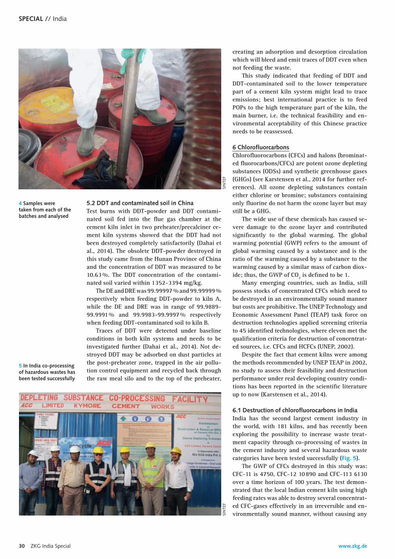
www.zkg.de30 ZKG India Special
SPECIAL // India
5.2 DDT and contaminated soil in ChinaTest burns with DDT-powder and DDT contami-nated soil fed into the flue gas chamber at the cement kiln inlet in two preheater/precalciner ce-ment kiln systems showed that the DDT had not been destroyed completely satisfactorily (Dahai et al., 2014). The obsolete DDT-powder destroyed in this study came from the Hunan Province of China and the concentration of DDT was measured to be 10.63 %. The DDT concentration of the contami-nated soil varied within 1352-3394 mg/kg.
The DE and DRE was 99.99997 % and 99.99999 % respectively when feeding DDT-powder to kiln A, while the DE and DRE was in range of 99.9889-99.9991 % and 99.9983-99.9997 % respectively when feeding DDT-contaminated soil to kiln B.
Traces of DDT were detected under baseline conditions in both kiln systems and needs to be investigated further (Dahai et al., 2014). Not de-stroyed DDT may be adsorbed on dust particles at the post-preheater zone, trapped in the air pollu-tion control equipment and recycled back through the raw meal silo and to the top of the preheater,
creating an adsorption and desorption circulation which will bleed and emit traces of DDT even when not feeding the waste.
This study indicated that feeding of DDT and DDT-contaminated soil to the lower temperature part of a cement kiln system might lead to trace emissions; best international practice is to feed POPs to the high temperature part of the kiln, the main burner, i.e. the technical feasibility and en-vironmental acceptability of this Chinese practice needs to be reassessed.
6 ChlorofluorcarbonsChlorofluorocarbons (CFCs) and halons (brominat-ed fluorocarbons/CFCs) are potent ozone depleting substances (ODSs) and synthetic greenhouse gases (GHGs) (see Karstensen et al., 2014 for further ref-erences). All ozone depleting substances contain either chlorine or bromine; substances containing only fluorine do not harm the ozone layer but may still be a GHG.
The wide use of these chemicals has caused se-vere damage to the ozone layer and contributed significantly to the global warming. The global warming potential (GWP) refers to the amount of global warming caused by a substance and is the ratio of the warming caused by a substance to the warming caused by a similar mass of carbon diox-ide; thus, the GWP of CO2 is defined to be 1.
Many emerging countries, such as India, still possess stocks of concentrated CFCs which need to be destroyed in an environmentally sound manner but costs are prohibitive. The UNEP Technology and Economic Assessment Panel (TEAP) task force on destruction technologies applied screening criteria to 45 identified technologies, where eleven met the qualification criteria for destruction of concentrat-ed sources, i.e. CFCs and HCFCs (UNEP, 2002).
Despite the fact that cement kilns were among the methods recommended by UNEP TEAP in 2002, no study to assess their feasibility and destruction performance under real developing country condi-tions has been reported in the scientific literature up to now (Karstensen et al., 2014).
6.1 Destruction of chlorofluorocarbons in IndiaIndia has the second largest cement industry in the world, with 181 kilns, and has recently been exploring the possibility to increase waste treat-ment capacity through co-processing of wastes in the cement industry and several hazardous waste categories have been tested successfully (Fig. 5).
The GWP of CFCs destroyed in this study was: CFC-11 is 4750, CFC-12 10 890 and CFC-113 6130 over a time horizon of 100 years. The test demon-strated that the local Indian cement kiln using high feeding rates was able to destroy several concentrat-ed CFC-gases effectively in an irreversible and en-vironmentally sound manner, without causing any
4 Samples were taken from each of the batches and analysed
SIN
TEF
5 In India co-processing of hazardous wastes has been tested success fully
SIN
TEF
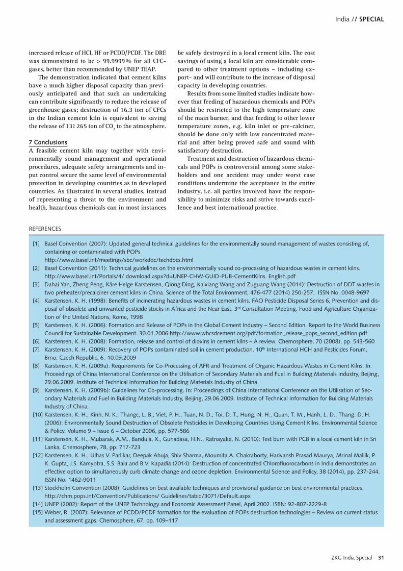
ZKG India Special 31
India // SPECIAL
increased release of HCl, HF or PCDD/PCDF. The DRE was demonstrated to be > 99.9999 % for all CFC-gases, better than recommended by UNEP TEAP.
The demonstration indicated that cement kilns have a much higher disposal capacity than previ-ously anticipated and that such an undertaking can contribute significantly to reduce the release of greenhouse gases; destruction of 16.3 ton of CFCs in the Indian cement kiln is equivalent to saving the release of 131 265 ton of CO2 to the atmosphere.
7 ConclusionsA feasible cement kiln may together with envi-ronmentally sound management and operational procedures, adequate safety arrangements and in-put control secure the same level of environmental protection in developing countries as in developed countries. As illustrated in several studies, instead of representing a threat to the environment and health, hazardous chemicals can in most instances
REFERENCES
[1] Basel Convention (2007): Updated general technical guidelines for the environmentally sound management of wastes consisting of, containing or contaminated with POPs
http://www.basel.int/meetings/sbc/workdoc/techdocs.html[2] Basel Convention (2011): Technical guidelines on the environmentally sound co-processing of hazardous wastes in cement kilns.
http://www.basel.int/Portals/4/ download.aspx?d=UNEP-CHW-GUID-PUB-CementKilns. English.pdf[3] Dahai Yan, Zheng Peng, Kåre Helge Karstensen, Qiong Ding, Kaixiang Wang and Zuguang Wang (2014): Destruction of DDT wastes in
two preheater/precalciner cement kilns in China. Science of the Total Environment, 476-477 (2014) 250-257. ISSN No. 0048-9697[4] Karstensen, K. H. (1998): Benefits of incinerating hazardous wastes in cement kilns. FAO Pesticide Disposal Series 6, Prevention and dis-
posal of obsolete and unwanted pesticide stocks in Africa and the Near East. 3rd Consultation Meeting. Food and Agriculture Organiza-tion of the United Nations, Rome, 1998
[5] Karstensen, K. H. (2006): Formation and Release of POPs in the Global Cement Industry – Second Edition. Report to the World Business Council for Sustainable Development. 30.01.2006 http://www.wbcsdcement.org/pdf/formation_release_pops_second_edition.pdf
[6] Karstensen, K. H. (2008): Formation, release and control of dioxins in cement kilns – A review. Chemosphere, 70 (2008), pp. 543-560[7] Karstensen, K. H. (2009): Recovery of POPs contaminated soil in cement production. 10th International HCH and Pesticides Forum,
Brno, Czech Republic, 6.-10.09.2009[8] Karstensen, K. H. (2009a): Requirements for Co-Processing of AFR and Treatment of Organic Hazardous Wastes in Cement Kilns. In:
Proceedings of China International Conference on the Utilisation of Secondary Materials and Fuel in Building Materials Industry, Beijing, 29.06.2009. Institute of Technical Information for Building Materials Industry of China
[9] Karstensen, K. H. (2009b): Guidelines for Co-processing. In: Proceedings of China International Conference on the Utilisation of Sec-ondary Materials and Fuel in Building Materials Industry, Beijing, 29.06.2009. Institute of Technical Information for Building Materials Industry of China
[10] Karstensen, K. H., Kinh, N. K., Thangc, L. B., Viet, P. H., Tuan, N. D., Toi, D. T., Hung, N. H., Quan, T. M., Hanh, L. D., Thang. D. H. (2006): Environmentally Sound Destruction of Obsolete Pesticides in Developing Countries Using Cement Kilns. Environmental Science & Policy, Volume 9 – Issue 6 – October 2006, pp. 577-586
[11] Karstensen, K. H., Mubarak, A.M., Bandula, X., Gunadasa, H.N., Ratnayake, N. (2010): Test burn with PCB in a local cement kiln in Sri Lanka. Chemosphere, 78, pp. 717-723
[12] Karstensen, K. H., Ulhas V. Parlikar, Deepak Ahuja, Shiv Sharma, Moumita A. Chakraborty, Harivansh Prasad Maurya, Mrinal Mallik, P. K. Gupta, J.S. Kamyotra, S.S. Bala and B.V. Kapadia (2014): Destruction of concentrated Chlorofluorocarbons in India demonstrates an effective option to simultaneously curb climate change and ozone depletion. Environmental Science and Policy, 38 (2014), pp. 237-244. ISSN No. 1462-9011
[13] Stockholm Convention (2008): Guidelines on best available techniques and provisional guidance on best environmental practices. http://chm.pops.int/Convention/Publications/ Guidelines/tabid/3071/Default.aspx
[14] UNEP (2002): Report of the UNEP Technology and Economic Assessment Panel, April 2002. ISBN: 92-807-2229-8[15] Weber, R. (2007): Relevance of PCDD/PCDF formation for the evaluation of POPs destruction technologies – Review on current status
and assessment gaps. Chemosphere, 67, pp. 109–117
be safely destroyed in a local cement kiln. The cost savings of using a local kiln are considerable com-pared to other treatment options – including ex-port- and will contribute to the increase of disposal capacity in developing countries.
Results from some limited studies indicate how-ever that feeding of hazardous chemicals and POPs should be restricted to the high temperature zone of the main burner, and that feeding to other lower temperature zones, e.g. kiln inlet or pre-calciner, should be done only with low concentrated mate-rial and after being proved safe and sound with satisfactory destruction.
Treatment and destruction of hazardous chemi-cals and POPs is controversial among some stake-holders and one accident may under worst case conditions undermine the acceptance in the entire industry, i.e. all parties involved have the respon-sibility to minimize risks and strive towards excel-lence and best international practice.
32 ZKG India Special
www.bauverlag.de
ZKG INTERNATIONAL Cement Lime GypsumVolume 67 “ZKG INTERNATIONAL” 2014 Volume 103 “ZEMENT”www.zkg.de
ISSN 0949-0205
Official Journal
Federal German Association of the Lime IndustryFederal German Association of the Gypsum Industry
Bauverlag BV GmbHAvenwedder Straße 55 PO Box 120, 33311 Gütersloh/Germany
Editor-in-Chief
Dr. Hubert BaierTel. +49 5241 [email protected]
Editor
Holger ReiffTel. +49 5241 [email protected]
Editorial Office Anke BrachtTel. +49 5241 [email protected]
English Translators
Robin B. C. Baker, Cranbrook/Great BritainH.-J. Puhl, Roßlau/GermanyM. Eley, Duisburg/Germany
Designer
Kerstin BerkenTel. +49 5241 80-2128 [email protected]
Advertising Manager
Ingo Wanders Tel. +49 5241 80-41973, Fax +49 5241 80-641973 [email protected]
Advertising rate card
No. 55, dated 01.10.2013
Managing Director
Karl-Heinz MüllerTel. +49 5241 80-2476
Director Sales and Subscription
Reinhard BrummelTel. +49 5241 80-2513
Marketing and Sales
Michael Osterkamp Tel. +49 5241 80-2167, Fax +49 5241 80-62167 [email protected]
Subscription Department
Subscriptions can be ordered directly from the publisher or at any bookshop. Bauverlag BV GmbH, PO Box 120, 33311 Gütersloh/Germany The Readers’ Service is available on Monday to Friday from 9.00 to 12.00 and 13.00 to 17.00 h (on Friday until 16.00 h). Tel. +49 5241 80-90884 E-Mail: [email protected] Fax +49 5241 80-690880
Subscription rates and period
The journal ZKG INTERNATIONAL appears monthly. The subscription is initially valid for one year and will renew itself automatically if it is not cancelled in writing not later than three months before the end of the subscription period.Annual subscription (including postage):Germany 398.00 €Students 276.00 € (against submission of current student’s card)Other 410.00 € (with surcharge for countries delivery by air mail)Single issue 40.00 € (including postage)
PublicationsUnder the provisions of the law the publishers acquire the sole publication and processing rights to articles and illustrations ac cepted for printing. Revisions and abridgements are at the dis cretion of the publishers. The publishers and the editors ac-cept no responsibility for unsolicited manuscripts. The author assumes the responsibility for the con-tent of articles identified with the author’s name. Honoraria for publications shall only be paid to the holder of the rights. The journal and all articles and illustrations contained in it are subject to copyright. With the exception of the cases per mitted by law, exploitation or duplication without the consent of the publishers is liable to punishment. This also ap-plies for recording and transmission in the form of data. The Bauverlag general terms and conditions can be found printed in full at www.bauverlag.de.
Representatives
France: Marc Jouanny International Media Press & Marketing 16, rue Saint Ambroise, 75011 ParisTel. +33 1 43553397 Fax +33 1 43556183Mobil +33 608975057 [email protected]
Italy: CoMediA di Garofalo Piazza Matteotti, 17/5, 16043 Chiavari Tel. +39 01 85590143 Mobil +39 335346932 [email protected]
Japan: ABC Enterprises Inc. Fukide Heights 103, 4-1-11 Toranomon, Minato-ku, Tokyo 105 Tel. +81 3 5404-7351 Fax +81 3 5404-7352
Russia and CIS: Dr. Eduard Bolshakov Group of Companies “ALIT” Instrumentalnaya str. 3B, office 218 P.O. Box 597, St. Petersburg 190068 Tel. +7 812 380 6572 Fax +7 812 703 7185 [email protected]
Hong Kong: Margaret [email protected] Asia Construction Information LtdUnit 1002, 10/F, Euro Trade Centre21–23 Des Voeux Road CentralCentral Hong KongTel. +852 2538 0011Fax +852 2875 0511
Indonesia: Bobby [email protected] BCI AsiaManggala Wanabakti Building8th Floor Wing A Suite 804-805Jl. Jend. Gatot Subroto 102708Jakarta 10270, IndonesiaTel. +62 21 5790-2930Fax +62 21 5790-2933
Brazil: Christiane Dias PereiraTerra MelhorRua Francisco Ricci 181/Vila EmaApto 61 A, São Jose dos Campos – São Paulo 12 243261Tel. +55 1298 [email protected]
Vietnam: Mr. Nguy Thanh [email protected] Asia Vietnam Co., Ltd.5th Floor, Tuoi Tre Tower60A Hoang Van Thu Street, Ward 9,Phu Nhuan DistrictHo Chi Minh City, SR/VietnamTel. +84 8 3997-4220Fax +84 8 3997-4150
The Philippines: Ms. Apple [email protected] Asia Philippines Inc.Units A & B 15/F Trafalgar PlazaH.V.Dela Costa St. Salcedo VillageMakati City/Philippines 1200Tel. +63 2 884-1122Fax +63 2 884-1121
Malaysia: Mr. Kelvin [email protected] Asia Construction Information Sdn BhdUnit 615, Blk E, Phileo Damansara I,Off Jln Damansara, No 9, Jln 16/11,Petaling Jaya, Selangor/Malaysia 46350Tel. +60 3 7661-1380Fax +60 3 7661-1381
Australia: Mr. Robert [email protected] Australia Pty Ltd52–56 Atchison StreetSt Leonards NSW/Australia 2065Tel. +61 2 9432-4142Fax +61 2 9432-4111
Setting + Lithography
Mohn Media Mohndruck GmbH, 33311 Gütersloh/Germany
Printers
Merkur DruckAm Gelskamp 20 32758 Detmold/Germany
Member Organizations
IVW Informationsgemeinschaft zur Feststellung der Verbreitung von Werbeträgern. H 7744
Advertiseremail
Contact NamePhone number
Page
FIVES [email protected]
Ms. C. Lucidarme+33/320437659
OBC
Gebr. Pfeiffer [email protected]
Ms. B. Becht-Hasenbein+49/631/4161-120
11
HGH Systèmes [email protected]
Mr. Edouard Campana+33/169354770
25
Köppern GmbH & Co. [email protected]
Mr. Dr. H. Günter+49/3731/2018-0
9
Loesche [email protected]
Ms. Karin Boeker-Mahr+49/211/5353-500
IFC, 1
FLSmidth Pfister [email protected]
Mr. Robert Krist+49/821/7949-283
OFC
Sicit [email protected]
Mr. Oreste Odelli+39/0444/450946
IBC
STARLINGER & CO. Gesellschaft [email protected]
Mr. Paul Niedl+43/1/59955-0
7
ADVERTISER INDEX IMPRINT
www.zkg.de
EVENT PREVIEW
Date Place
EventContact
11.11. – 13.11.2014 19th AUCBM – Arab Union for Cement and Building Materialswww.aucbm.org
Marrakech/Morocco
11.11.2014 9th Annual SEADMA Conferencewww.drymix.infoSingapore
25.11. – 28.11.2014 BAUMA China 2014 – Intl. exhib. on constr. machines and technologieswww.bauma-china.com
Shanghai/China
19.01. – 24.01.2015 BAU 2015 – Intl. fair on constr. materials, technologies and equipmentwww.bau-muenchen.com
Munich/Germany
20.04.2015 5th International Drymix Mortar Conference (idmmc five)www.drymix.info
Nuremberg/Germany
21.04.2015 European Coatings Congress (ECC), Construction Chemical Sessionswww.european-coatings-show.com
Nuremberg/Germany
16.09. – 18.09.2015 19th International Conference on Building Materials (Ibausil)www.ibausil.de
Weimar/Germany
15.10. – 17.10.2015 15th Intl. Congress on Polymers in Concrete (ICPIC)www.drymix.info
Singapore
11.04. – 17.04.2015 BAUMA 2016 – Intl. exhibition on constr. equipment and technologieswww.bauma.de
Munich/Germany

✔ RETARD THE SETTING OF GYPSUM
✔ INCREASE FLUIDITY
✔ GIVES A MORE HOMOGENEOUS
FINAL PRODUCT
✔ HIGH PERFORMANCE AT
LOW DOSAGE
✔ BIODEGRADABLE PRODUCT
✔ NOT AFFECTING STRENGTH
✔ NOT NOURISHING MOLDS
Contact us:T 0039 0444 450 [email protected]
The Right Product forSuccessful Projects
The Multifunctional Additive
www.plastretard.com
