excellent metallurgy & high-grade trenching results … · 12/01/2017 · the drilling is...
TRANSCRIPT

12 January 2017
EXCELLENT METALLURGY & HIGH-GRADE TRENCHING RESULTS FOR YONGWON GRAPHITE PROJECT, SOUTH KOREA
(drilling now planned to test EM conductor from surface)
Excellent metallurgical results produce a concentrate grade of 97% graphitic carbon
Further metallurgical testing planned to test to spherical graphite processing potential - to feed the world’s leading lithium-ion battery manufacturing market in South Korea
High-grade trenching results of 9.7 metres grading 11.7% graphitic carbon demonstrate substantial thickness and high-grade of the Yongwon graphite deposit
Electromagnetic survey defines a highly conductive graphitic unit over more than 400 metres of strike length, which remains open to the east and at depth
Drilling programme planned from early Q2 to test the conductive graphitic unit with the aim to define a maiden Indicated Resource
Peninsula Mines Ltd (ASX: PSM) is pleased to announce high-grade concentrate results, averaging 97% total graphitic carbon (TGC) and 87.3% graphite recovery, from metallurgical testwork conducted on representative samples from the Company’s 100% owned Yongwon Graphite Project in South Korea (see Figure 1 for location).
In addition, a high-grade trenching intersection of 9.7 metres (m) grading 11.7% TGC including 2.5m @ 16.9% TGC and 2.45m @ 16.1% TGC has been achieved from initial trenching across the outcropping graphitic unit (see Figure 1 for location and Figure 2, graphitic rock-sample grading 16% TGC). This trenching has not yet tested the entire width of the graphitic unit (estimated to be at-least 10m wide at surface), and further trenching is planned along the strike of the unit.
A moving loop electromagnetic (MLEM or EM) survey across the Yongwon graphitic unit has also been conducted. This EM survey has been very successful, defining the highly conductive graphitic unit dipping moderately to the northeast from surface, and continuous to at-least 180m down dip and extending the strike length to >400m, open to the east (see Figure 1 and Figure 4).
Additional trenching and a drilling programme has now been planned to test the graphitic unit from surface to a depth of ~120m below surface (~200m down-dip) on 5 x 80m spaced drilling traverses. The programme will include 16 to 23 diamond drill holes (see Figure 4) for 1,100m to 1,500m and, depending on the continuity of thickness and grade of the graphitic unit, this is expected to be adequate drilling density to define a maiden Indicated Resource for the Yongwon Graphite Project. The drilling is expected to commence early in the second quarter 2017.
Peninsula CEO Jon Dugdale commented, “We are very pleased to have obtained these outstanding metallurgical graphite concentrate results and recoveries for the Yongwon Graphite Project.
“Combined with the high-grade trenching results over substantial width, and EM survey results that indicate a continuous conductive unit at depth, these results have presented a high-grade drilling target and the opportunity to define a maiden Indicated graphite resource.”
For
per
sona
l use
onl
y

Page 2 of 23
Figure 1: Yongwon Graphite Project, mapped graphite unit, new channel sampling results and EM conductor
Inset: Close up of channel sampling locations and high-grade graphite results
Figure 2: High-grade flake-graphite sample from outcropping graphitic unit at Yongwon (16% TGCD1)
New channel sampling YC0001 – 0015: 9.7m @ 11.7% TGC inc. 2.5m @ 16.9% TGC & 2.45m @ 16.1% TGC
EM conductor, open down plunge>> 40°
Gran
ted
Tenem
en
t Bo
un
dary
Eum
seon
g 32
-1
25°
YGC01
YGC02
For
per
sona
l use
onl
y

Page 3 of 23
Metallurgical results produced 97% concentrate grade and 87.3% graphite recovery:
Following initial encouraging results from metallurgical testwork conducted at NAGROM laboratories in PerthD2, IMO Project Services (IMO) were commissioned to conduct further testwork aimed at generating an optimal processing flowsheet for the production of a high-grade graphite concentrate, suitable for further down-stream processing to feed the lithium-ion graphite battery anode market.
A 50 kilogram (kg) composite sample was collected from trenches and outcrops of the Yongwon graphitic unit, which averaged a calculated head-grade of 14.4% TGC.
IMO conducted multiple grinding, cleaner and flotation tests and optimised the flowsheet based on an initial coarse grind “rougher” flotation stage then 5 re-grind, cleaner and flotation stages, with the addition of reagents (e.g. Na2SiO3), to achieve an average concentrate grade based on Loss on Ignition at 1000°C (LOI1000) of 97% TGC and an overall graphite recovery of 87.3% based on TGC Leco analyser assays by NAGROM Laboratories (see Table 1 below).
Table 1: Yongwon Graphite Project final graphite concentrate results and recovery:
Size Fraction Mass Total Carbon *LOI 1000°C TGC Recovery
µm % % % %
>106 8.2% 97.6 97.9
>75 13.7% 97.8 98.2
<75 78.1% 96.6 96.7
Calc. Head 100.0% 96.8 97.0 87.3% *LOI 1000°C is the most accurate method to determine Total Graphitic Carbon at high concentrations (>90% TGC)
The additional re-grind stages have resulted in a very high concentrate grade of 97% TGC, but have reduced the distribution of coarser flake material in the final concentrate. However, the high-grade of the concentrate produced from the Yongwon graphitic material indicates suitability for further down-stream processing including micronisation then spheronization to produce a spherical graphite concentrate for final purification and coating prior to lithium-ion battery anode production. Testing to determine the spheronization potential of the Yongwon graphite concentrate will commence immediately, so that a suitable sample-product can be produced for discussions with potential offtake partners in South Korea and North Asia generally.
Figure 3: Graphite flotation at NAGROM laboratories
For
per
sona
l use
onl
y

Page 4 of 23
New trenching results indicate high-grades over substantial width:
The Yongwon graphitic unit occurs on the granted Eumseong 32-1 tenement sub-block, outcropping along a NW-SE trending ridge and dipping moderately to the northeast (see Figure 1).
The graphitic unit has been traced over a greater than 300m strike length and intermittently across widths of up to 15m at surface.
Previous Korean Mineral Promotion Corporation (KMPC) costean/trench sampling in the 1970s included 8 costeans along the 300m outcropping strike extent and reported grades ranging between 8.5% and 18.3% TGC. The Company has previously released limited rock-chip sampling including a hand chipped sample run of 4.6m @ 9.05% TGC across an exposure in a historical KMPC costeanD2.
Channel sampling aimed at testing the entire width of the graphite unit on 80m spaced sections commenced in November 2016 and included the channel sampling of one re-excavated KMPC costean, using a diamond rock-saw, prior to the programme being suspended due to the winter snows. Assay results from this initial costean returned an intersection of 9.7m (~7.5m true width) @ 11.7% TGC including 2.5m @ 16.9% TGC and 2.45m @ 16.1% TGC across approximately two-thirds of the Yongwon graphitic unit estimated width (see Figure 1). Locations and analytical results are listed in Appendix 1.
Channel sampling will continue to test the graphitic unit on 80m spaced sections across the entire width of the unit once the snow melts and access is possible. This work is planned to commence early in the second quarter of 2017.
EM geophysical results have defined a graphitic conductor at depth and along strike:
In November 2016, the Company commissioned Southern Geoscience Consultants (SGC) of Perth to undertake a moving loop electromagnetic (EM) survey across the Yongwon graphitic unit. The purpose of the survey was to determine the EM (conductivity) response of the outcropping graphitic unit and map the extent and geometry of the conductive unit along strike and at depthD3.
The EM survey proved very effective in defining the graphitic unit, due to the sharp conductivity contrast between the highly conductive graphitic schist and the low conductivity surrounding country rock, predominantly biotite gneiss, porphyry and granite.
EM survey readings were taken on 8 x 100m spaced local-grid lines, 50m spaced stations, orthogonal to the mapped graphitic unit. Data was received on 30 channels from early to late time (shallow to deeper). The anomaly detected on Channel 5 is plotted (see Figures 1 and 4) approximating the response from outcrop to ~200m down dip. Two clear conductive peaks are labelled YGC01 and YGC02. YGC01 is the strongest anomaly, occurring immediately down dip/plunge from the high-grade trenching results (e.g. 9.7m @ 11.7% TGC). YGC02 is of interest as it extends the target to beyond the mapped outcropping graphitic unit.
The highly graphitic conductive unit detected by the EM survey has been modelled to continue over a strike length of >400m and to a depth down dip of >180m (see Figure 4). The EM model, combined with surface mapping of the sub-cropping and outcropping graphitic unit, has defined a target that dips at 45° to the northeast (NE) and flattens to 25° to the NE along strike to the southeast (SE). The EM anomaly remains open to the east and at depth indicating that further exploration could increase the size of the modelled target. F
or p
erso
nal u
se o
nly

Page 5 of 23
Figure 4: Yongwon graphitic unit looking south modelled from outcrop and EM results with proposed drilling
Drilling programme planned with the aim to define an Indicated graphite Resource:
On the basis of the positive metallurgical results indicating potential for a 97% TGC concentrate, high-grade trenching results over substantial widths, and the EM survey results indicating a continuous conductive unit over a strike length of 400m and dip extent of at least 180m, a drilling programme has been planned to test the graphitic unit on 80m spaced sections (see Figure 4 above) with the objective of defining an Indicated Resource.
The initial four cross sections will include a planned 16-hole diamond drilling programme from 9 drill-pads (see Figure 4) for approximately 1,100m. The proposed programme has been submitted to the Korean Resources Corporation (KORES), a Korean Government agency which provides funding for the exploration and development of mineral resources by Korean registered companies (e.g. subsidiary, Suyeon Mining). KORES funding support is sought for 7 additional holes on the eastern side of this initial programme. Application has also been filed with the Local Government for forest access approval. The Company anticipates drilling consent and access approval by March 2017, with drilling planned to commence early in the second quarter 2017, coinciding with the start of the field season.
JORC 2012 Table 1, Sections 1 and 2, below, details sampling and analytical techniques used, and the data and exploration results reporting criteria.
Appendix 1 contains locations and assay details of channel samples collected from the Yongwon Graphite Project.
For more information please contact: Jon Dugdale, FAusIMM Chief Executive Officer Phone: +61 402 298 026 Email: [email protected]
YGC01 YGC02
For
per
sona
l use
onl
y
Page 6 of 23
About Peninsula Mines Ltd
Peninsula Mines Ltd is an Australian listed exploration/development company focused on developing the outstanding opportunities for mineral discovery within South Korea. Peninsula’s strategy is to focus on mineral commodities which have a positive price outlook and offer potential for off-take or strategic partnerships in-country.
The Company has established and is growing a portfolio of highly prospective graphite, lithium, gold-silver and zinc-silver-polymetallic projects in South Korea that all offer significant exploration potential.
Full versions of all the company's releases are available for download from the Company's website www.peninsulamines.com.au
The material and/or releases referenced in this release are listed below:
D1 High Graphite Grades at Yongwon Project, 19 July 2016 D2 Jumbo and Very Large Identified at South Korean Graphite Projects, 20 September 2016 D3 Establishing multiple drilling targets across key projects in South Korea, 21 November 2016
Forward looking Statements This release contains certain forward looking statements. These forward-looking statements are not historical facts but rather are based on Peninsula Mines Ltd’s current expectations, estimates and projections about the industry in which Peninsula Mines Ltd operates, and beliefs and assumptions regarding Peninsula Mines Ltd’s future performance. Words such as “anticipates”, “expects”, “intends”, “plans”, “believes”, “seeks”, “estimates” “potential” and similar expressions are intended to identify forward-looking statements. These statements are not guarantees of future performance and are subject to known and unknown risks, uncertainties and other factors, some of which are beyond the control of Peninsula Mines Ltd, are difficult to predict and could cause actual results to differ materially from those expressed or forecasted in the forward-looking statements. Peninsula Mines Ltd cautions shareholders and prospective shareholders not to place undue reliance on these forward-looking statements, which reflect the view of Peninsula Mines Ltd only as of the date of this release. The forward-looking statements made in this release relate only to events as of the date on which the statements are made. Peninsula Mines Ltd does not undertake any obligation to release publicly any revisions or updates to these forward-looking statements to reflect events, circumstances or unanticipated events occurring after the date of this presentation except as required by law or by any appropriate regulatory authority. Competent Person’s Statements The information in this release that relates to Exploration Results, Mineral Resources or Ore Reserves is based on information compiled by Mr Daniel Noonan, a Member of the Australian Institute of Mining and Metallurgy. Mr Noonan is an Executive Director of the Company. Mr Noonan has sufficient experience which is relevant to the style of mineralisation and type of deposit under consideration and to the activity which he is undertaking to qualify as a Competent Person as defined in the 2012 Edition of the ‘Australasian Code for Reporting of Exploration Results, Mineral Resources and Ore Reserves’. Mr Noonan consents to the inclusion in the release of the matters based on this information in the form and context in which it appears. The information in this release that relates to metallurgical test work is based on information compiled and / or reviewed by Mr Peter Adamini who is a Member of The Australasian Institute of Mining and Metallurgy. Mr Adamini is a full-time employee of IMO Project Services. Mr Adamini consents to the inclusion in the report of the matters based on his information in the form and context in which it appears.
For
per
sona
l use
onl
y

Page 7 of 23
JORC Code, 2012 Edition: Table 1 Section 1: Sampling Techniques and Data
(Criteria in this section apply to all succeeding sections.)
Criteria JORC – Code of Explanation Commentary
Sampling techniques
Nature and quality of sampling (e.g. cut channels, random chips, or specific specialised industry standard measurement tools appropriate to the minerals under investigation, such as down hole gamma sondes, or handheld XRF instruments, etc). These examples should not be taken as limiting the broad meaning of sampling.
At Yongwon, 14 samples were collected from a re-excavated trench. The samples were from a rock-saw cut channel in the floor of the trench approximately 7cm wide and 7cm deep. The channel was cut horizontally across the moderately, northeasterly dipping graphitic unit.
The sample quality was excellent, fresh to partially oxidised rock. The entire sample was collected in the intervals ranging from 0.2m to 1.0m.
The channel/rock chip samples were analysed for Total Carbon (TC %), Total Graphitic Carbon (TGC %), Total Organic Carbon (TOC%) and Total Inorganic Carbon (TIC %) as well as sulphur (S %) by NAGROM laboratory in Perth, Australia.
The NAGROM analyses utilised a LECO analyser, gravimetric analyses where C and S values were determined from mass differences (determined using precision scales) during the high temperature heating and subsequent CO2 and SO2 generation in the analyser.
The analytical results are tabled as Appendix 1, below. The locations of the sample points are shown on Figure 1. All coordinates were in WGS84 UTM Zone 52N coordinate system.
This announcement also refers to results of metallurgical studies on samples collected from the Yongwon graphite unit. The metallurgical composite sample (~50kg) was made up from 12, 4kg to 5kg rockchip/channel samples collected from previous sample sites, in calico bags with vegetative material and soil removed. The samples were dispatched to NAGROM laboratory in Perth, Australia, then transferred to Independent Metallurgical Operations (IMO) in Perth for the metallurgical testing.
For
per
sona
l use
onl
y

Page 8 of 23
Criteria JORC – Code of Explanation Commentary
Include reference to measures taken to ensure sample representivity and the appropriate calibration of any measurement tools or systems used.
The results released in this announcement are rock-saw cut channels, approximately 7cm wide, taken along the floor of the hand excavated trench. Sampling was undertaken as close as possible to normal to strike of the moderately dipping graphitic unit.
The channel cut samples were collected along intervals ranging from 0.2m to 1.0m, with care taken to ensure that they were representative of each interval. Sample quality was excellent, fresh to partially oxidised rock.
Sampled intervals were measured using a tape measure and referenced by chain and compass survey from Digital GPS surveyed pegs for accurate 3D spatial location.
Aspects of the determination of mineralisation that are material to the Public Report. In cases where ‘industry standard’ work has been done this would be relatively simple (e.g. ‘reverse circulation drilling was used to obtain 1 m samples from which 3 kg was pulverised to produce a 30 g charge for fire assay’). In other cases more explanation may be required, such as where there is coarse gold that has inherent sampling problems. Unusual commodities or mineralisation types (e.g. submarine nodules) may warrant disclosure of detailed information.
The surface channel samples were collected from a re-excavated trench. A channel approximately 7cm wide, was cut horizontally across the moderately, northeasterly dipping, graphitic unit. The entire channel cut sample was collected in the intervals ranging from 0.2m to 1.0m. The graphite was evenly distributed within the graphitic unit. The entire exposed interval was sampled and dispatched as individual samples to NAGROM laboratories in Perth, WA. The graphitic samples, averaging 2kg to 9kg, were dried at 105oC. Samples post drying were crushed to a nominal top size of 6.3mm using a jaw crusher. If the sample mass exceeded 2.5kg, the sample was then riffle split to generate a sub-sample for pulverisation. Alternatively, if the sample mass was <2.5kg, the entire sample was pulverised.
The sample was pulverised using a LM5 pulveriser until 80% of the sample passed 75 microns. A ~150g subsample of the pulverised material was then randomly selected for analysis with the balance of the pulverised material retained for possible future metallurgical studies.
NAGROM utilised a LECO analyser and gravimetric analyses, where C and S values were determined from mass differences (using precision scales) during the high temperature heating and subsequent CO2 and SO2 generation inside the analyser. This method was considered near total for C and S and was the preferred method for accurate graphite sample analysis.
From these analyses, the Total Carbon, Total Graphitic Carbon (TGC), Organic Carbon and Inorganic Carbon (as carbonate) and Sulphur were reported (Appendix 1). In addition, a metallurgical composite sample (~50kg), made up of 12, 4kg to 5kg rock chip samples collected from previous sample sites, was collected in calico bags with vegetative material and soil removed. The samples were dispatched to
For
per
sona
l use
onl
y

Page 9 of 23
Criteria JORC – Code of Explanation Commentary
NAGROM in Perth, Australia, then transferred to Independent Metallurgical Operations (IMO) in Perth for the metallurgical testing. The metallurgical samples were combined and crushed to >3.35mm then sub-samples (5kg) subjected to multiple grinding, cleaning and flotation stages prior to generation of final graphite concentrate. This concentrate was then assayed by NAGROM laboratories in Perth, WA, using the methodology described above for the channel samples.
Drilling techniques
Drill type (e.g. core, reverse circulation, open-hole hammer, rotary air blast, auger, Bangka, sonic, etc) and details (eg core diameter, triple or standard tube, depth of diamond tails, face-sampling bit or other type, whether core is oriented and if so, by what method, etc).
No drilling has been undertaken by the company and no commentary is being presented here on past drilling results. Drilling referenced in this release is proposed only.
Drill sample recovery
Method of recording and assessing core and chip sample recoveries and results assessed.
No drilling has been undertaken by the company and no commentary is being presented here on past drilling results. Drilling referenced in this release is proposed only. In the case of the channel sampled interval, even sized samples were collected from each of the 14 sampled intervals that constitute the channel sample. There was no sample loss and samples of consistent width and depth were cut for each interval. There is no loss of fines and each sample was considered fully representative of the interval sampled.
Measures taken to maximise sample recovery and ensure representative nature of the samples.
Whether a relationship exists between sample recovery and grade and whether sample bias may have occurred due to preferential loss/gain of fine/coarse material.
Logging Whether core and chip samples have been geologically and geotechnically logged to a level of detail to support appropriate Mineral Resource estimation, mining studies and metallurgical studies.
No drilling has been undertaken by the company and no commentary is being presented here on past drilling results. Drilling referenced in this release is proposed only. All costean sample intervals were photographed prior to and post- cutting. The geology of each sampled interval was recorded in a field notebook and transferred to an Excel spreadsheet. Logging included rock type, degree of weathering and oxidation, gangue minerals observed, nature of the mineralisation, width and depth of each sample. Structural information, such as bedding dip and direction were collected. Sketch maps of the costean and sampled intervals were also made. The geology for the entire sampled interval was recorded. There were no areas of sample loss within any of the sampled intervals.
Whether logging is qualitative or quantitative in nature. Core (or costean, channel, etc) photography.
The total length and percentage of the relevant intersections logged.
For
per
sona
l use
onl
y

Page 10 of 23
Criteria JORC – Code of Explanation Commentary
Sub-sampling techniques and sample preparation
If core, whether cut or sawn and whether quarter, half or all core taken.
No drilling has been undertaken by the company and no commentary is being presented here on past drilling results. Drilling referenced in this release is proposed only.
If non-core, whether riffled, tube sampled, rotary split, etc and whether sampled wet or dry.
All channel samples were taken with two parallel saw cuts with the rock between the cuts removed using a geology hammer and/or a mallet and chisel. The entire sampled interval was sawn and a rubber mat was used to help funnel material into a calico sample bag. Samples were dried in the Company’s secure core cutting shed using a gas heater prior to dispatch. Metallurgical samples were all collected dry. The samples were taken using a geology hammer and/or a mallet and chisel. Samples were collected in a calico bag using a piece of rubber matting to funnel rock chips into the open sample bag.
For all sample types, the nature, quality and appropriateness of the sample preparation technique.
In all cases, the entire sample was crushed and then split to produce a subsample for analysis. The details of the applicable sample preparation have been discussed more fully in subsequent sections.
Quality control procedures adopted for all sub-sampling stages to maximise representivity of samples.
The channel cut sample was collected in intervals ranging from 0.2m to 1.0m ensuring that a representative sample was taken across the length and breadth of each sampled interval. Sample quality was excellent and samples included fresh to partially oxidised rock. The Company included blanks and Certified Reference Material as part of the channel sample analysis. The results of the QA/QC samples were within statistically acceptable limits.
Measures taken to ensure that the sampling is representative of the in situ material collected, including for instance results for field duplicate/second-half sampling.
As previously stated, the entire channel cut sample was collected in the intervals ranging from 0.2m to 1.0m ensuring a representative sample. At this point in time, no duplicate samples have been taken at any of the sample sites. No sample splits have been analysed other than those routinely analysed by the laboratory as part of their own internal QA/QC process.
Whether sample sizes are appropriate to the grain size of the material being sampled.
The sample size was considered more than adequate to assess TGC content of the graphite mineralisation from the Yongwon project.
For
per
sona
l use
onl
y

Page 11 of 23
Criteria JORC – Code of Explanation Commentary
Quality of assay data and laboratory tests
The nature, quality and appropriateness of the assaying and laboratory procedures used and whether the technique is considered partial or total.
All metallurgical samples were rock chip samples collected using a hammer, ± chisel, rubber mat and calico bag. All channel samples were taken using a rock saw and a mallet and chisel.
At NAGROM, samples were dried at 105oC. Samples post drying were crushed to a nominal top size of 6.3mm using a jaw crusher. If the sample mass exceeded 2.5kg, the sample was then riffle split to generate a sub-sample for pulverisation. Alternatively, if the sample was <2.5kg, the entire sample was pulverised.
The sample was pulverised using a LM5 pulveriser until 80% of the sample passed 75 microns. A ~150g subsample of the pulverised material was then randomly selected for analysis with the balance of the pulverised material retained for future use.
The NAGROM analyses utilised a LECO analyser and were gravimetric analyses, where C and S values were determined from mass differences (using precision scales) during the high temperature heating and subsequent CO2 and SO2 generation inside the analyser. This method was considered near total for C and S and was the globally preferred method for accurate graphite sample analysis.
From these analyses, the Total Carbon, Total Graphitic Carbon (TGC), Organic Carbon and Inorganic Carbon (as carbonate) and Sulphur were reported (Appendix 1).
The assays were considered total for the key elements of C and S. Additional XRF analyses of gangue minerals (such as SiO2, CaO, K2O, Al2O3 etc.) were also undertaken as part of the overall analysis suite. These results were not considered material and have been excluded from this release.
For geophysical tools, spectrometers, handheld XRF instruments, etc, the parameters used in determining the analysis including instrument make and model, reading times, calibrations factors applied and their derivations, etc.
The Company commissioned Southern Geoscience Consultants (SGC) of Perth to undertake a moving loop electromagnetic (MLEM) survey across the Yongwon graphitic unit. The purpose of the survey was to determine the EM (conductivity) response of the outcropping graphitic unit and map the extent and geometry of the conductive unit along strike and at depth. The geophysical programme parameters were as follows: Planning/Supervision: Southern Geoscience Consultants Pty Ltd (SGC) Survey Configuration: Moving Loop TEM (MLEM) – coincident loop configuration TX Loop Size: 100m x 100m Transmitter: ZT-30 Transmitter Power: 12V Battery Receiver: SMARTem24 Sensor: 100m x 100m loop wire – single vertical (Z) component Line Spacing: 100m Line Bearing: 036° Station Spacing: 50m
For
per
sona
l use
onl
y

Page 12 of 23
Criteria JORC – Code of Explanation Commentary
TX Frequency: 2 Hz (125 msec time base) Duty cycle: 50% Current: 6 to 6.5 Amp Stacks: 128 stacks Readings: At least 3 repeatable readings per station Powerline Frequency: 60 Hz Data was received on 30 channels from early to late time (shallow to deeper). The anomaly detected on Channel 5 is plotted (see Figures 1 and 4) approximating the response from outcrop to ~200m down dip.
Nature of quality control procedures adopted (e.g. standards, blanks, duplicates, external laboratory checks) and whether acceptable levels of accuracy (i.e. lack of bias) and precision have been established.
The Company included blank and CRM samples as part of the channel sample analyses. No blank or CRM samples were included as part of the metallurgical analysis. In addition, NAGROM undertakes routine blank, CRM and repeat analyses as part of the labs own internal QA/QC procedures. The results of the Company’s and the laboratory’s own internal QA/QC do not indicate any issues with the assay results reported herewith.
No blind sample repeats have been undertaken at this point in time. The labs routine sample repeats show excellent correlation.
Verification of sampling and assaying
The verification of significant intersections by either independent or alternative company personnel.
The graphite intersection reported in this release has been composited independently by two executives of the Company and verified, based on review of sampling and analytical techniques.
The use of twinned holes. No drilling has been undertaken by the company and no commentary is being presented here on past drilling results. Drilling referenced in this release is proposed only.
Documentation of primary data, data entry procedures, data verification, data storage (physical and electronic) protocols.
Assay results were stored in an Excel database. All results were checked by the responsible geologist on entry to the database. The Company’s data was stored in an Excel database and routinely transferred to the Perth Head Office.
Discuss any adjustment to assay data.
The data presented in the accompanying Appendix 1 is raw laboratory data. The organic carbon and inorganic carbon content were calculated using the results of the total and graphitic carbon and non-inorganic carbon analyses. This is standard practice in the reporting analyses of various carbon species.
Location of data points
Accuracy and quality of surveys used to locate drill holes (collar and down-hole surveys), trenches, mine workings and other locations used in Mineral Resource estimation.
No drilling has been undertaken by the company and no commentary is being presented here on past drilling results. Drilling referenced in this release is proposed only.
For
per
sona
l use
onl
y

Page 13 of 23
Criteria JORC – Code of Explanation Commentary
A central baseline for the EM grid was surveyed using a Digital GPS unit accurate to <10cm in X, Y & Z coordinate space. Control points were also surveyed at each of the existing KMPC costeans and these surveyed pegs were used to reference the location of each channel sample to an accuracy of +/- 0.5m using a chain, compass and clinometer survey to spatially locate the start and end of each channel sample.
Specification of the grid system used.
All sample sites were surveyed in the UTM WGS84 zone 52N coordinate system.
Quality and adequacy of topographic control.
Topographic control on sample sites was as surveyed, to an accuracy of +/- 0.5m. Geophysical measurement locations were determined using a hand-held Garmin GPS60CSx. The accuracy of this unit at most sample sites was +/- 5m to 10m. Other topographic controls were based on The National Geographic Information Institute (NGII), 1:5,000 scale digital contour data available for the entire country.
Data spacing and distribution
Data spacing for reporting of Exploration Results.
The initial graphite channel-sampling intersection was based on continuous channel sampling across the reported intersection. Further channel sampling and proposed drilling is planned to be conducted at 80m section intervals.
Whether the data spacing and distribution is sufficient to establish the degree of geological and grade continuity appropriate for the Mineral Resource and Ore Reserve estimation procedure(s) and classifications applied.
The initial trench/costean channel sampling was part of a broader sampling programme with planned sectional-spacing of 80m with continuous sampling to be undertaken across the width of the outcropping graphitic unit, and it was considered that this would be sufficient to establish the degree of geological and grade continuity appropriate for a future Mineral Resource and Ore Reserve estimation.
Whether sample compositing has been applied.
None of the rock chip assay results have been composited. The assay results for each channel sampled interval have been reported in Appendix 1, both the true and apparent widths are tabulated. The metallurgical analyses discussed in this release were undertaken using a ~50kg composited sample. The selection of individual samples have been discussed previously.
Orientation of data in relation to geological structure
Whether the orientation of sampling achieves unbiased sampling of possible structures and the extent to which this is known, considering the deposit type.
The channel samples were all sawn as close as possible to perpendicular to structure, given the limitations of the pre-existing costean. All channel samples accurately reflected the grade of the sampled interval.
For
per
sona
l use
onl
y

Page 14 of 23
Criteria JORC – Code of Explanation Commentary
If the relationship between the drilling orientation and the orientation of key mineralised structures is considered to have introduced a sampling bias, this should be assessed and reported if material.
No drilling has been undertaken by the company and no commentary is being presented here on past drilling results. Drilling referenced in this release is proposed only. The sawn channel was taken as close to normal to the graphitic unit’s strike as possible. The sample location was along the floor of the trench and was governed by the topography of the trench floor, every effort was made to keep the channel attitude as close to horizontal as possible.
Sample security
The measures taken to ensure sample security.
All samples were collected into pre-labelled calico sample bags. The specific details of each sample and sample site were recorded into a field notebook and later transferred to an Excel spreadsheet. Samples were packed into cardboard cartons and dispatched via DHL Global Forwarding to NAGROM Laboratories, Australia. The NAGROM samples were air freighted to Perth where they were held for assessment by AQIS (Australian Quarantine Inspection Service). The Company’s import declaration outlined where the sample batch was sourced and the nature of the sampled material (e.g. rock chips, soil, core etc.). All the Company’s graphite samples were declared as surface samples and heat treated if required by AQIS to destroy any soil or airborne pathogens prior to release to NAGROM. Metallurgical samples were declared free of organic material by AQIS and thus the sample heat treatment step was not required. This was considered important by IMO to minimise clay baking onto graphite flakes and to optimise concentrate grade and recovery.
Audits or reviews
The results of any audits or reviews of sampling techniques and data.
The NAGROM Laboratory, Kelmscott has been visited by Company personnel and met full international standards. NAGROM is internationally recognised, particularly in the field of metallurgical evaluations. Similarly, the IMO metallurgical laboratory in Welshpool, Perth, WA has been visited by Company personnel and meets full international standards. IMO are also internationally recognised, particularly in the field of metallurgical evaluations.
(Criteria in this section apply to all succeeding sections.)
For
per
sona
l use
onl
y

Page 15 of 23
Section 2: Reporting of Exploration Results (Criteria listed in the preceding section also apply to this section.)
Criteria JORC – Code of Explanation Commentary
Tenement and land tenure status
Type, reference name/number, location and ownership including agreements or material issues with third parties such as joint ventures, partnerships, overriding royalties, native title interests, historical sites, wilderness or national park and environmental settings.
The Yongwon graphitic unit is located within the granted 68-hectare area of the Eumseong 32-1 tenement sub-block. The graphitic schist unit outcrops along a NW-SE trending ridge and dips moderately to the northeast (Figure 1). The Company has also filed applications over the surrounding Eumseong 32 sub-blocks as well as the adjoining Eumseong 11, 21 & 22 blocks. Each Korean tenement block covers a 1-minute graticule and has a nominal area of 276 hectares. The Company has 100% sole rights over each tenement for graphite. Graphite, like other industrial minerals, is classified as a minor mineral under Korean Mineral Law. In the case of minor minerals such as graphite, each 1-minute graticule block is further subdivided into four 30”x 30” sub-blocks (sub-blocks are only applicable for industrial minerals and road metal and dimension stone quarry permits). The Company must complete and file a Mineral Deposit Survey (MDS) over each sub-block to secure a 6-year exploration right for each sub-block. There are no native title interests in Korea. It is a generally accepted requirement that mineral title holders gain the consent of local land owners and residents before undertaking any major exploration activity, such as drilling. The Yongwon graphite mineralisation is located on forest land owned and managed by the Chungcheonbuk-do Provincial Government.
For
per
sona
l use
onl
y

Page 16 of 23
Criteria JORC – Code of Explanation Commentary
The security of the tenure held at the time of reporting along with any known impediments to obtaining a licence to operate in the area.
On 24 October 2016, the Company was granted a 3-year exploration right over the Eumseong 32-1 tenement sub-block, a 68-hectare area encompassing all the known graphite mineralisation at the Yongwon Graphite Project. The initial 3-year exploration period can be extended to 6 years upon submission of a supplementary application to the Ministry. Further, the Company can convert the exploration licence to a formal mining right application upon the filing of a prospecting report. A recent change to the Korean Mineral Law now requires that a mineral right holder must include details of the defined Mineral Resource with any application for extension to an Exploration Right or for the grant of a full Mining Right. There are minimum Resources requirements that must now be met at each stage of the application process. Upon approval of a Mining Right the Company has 3 years to file and have a Mine Planning Application (MPA) approved. The MPA is submitted to and approved by the Local Government and is akin to local council planning approval. As part of the MPA process, the title holder must secure a “no objection certificate” from the residents of the local village(s). An MPA primarily covers design, implementation, environmental and safety aspects of all surface activities associated with the planned mining venture. The approval of the MPA then grants the mining Right holder a 20-year production period that can be extended further upon application, provided all statutory requirements have been met over the life of the mine. From the date of grant of the Mining Right, the title holder has a 3-year period in which mine production must commence. During this 3-year period, the title holder must make a minimum level of investment on plant and mine infrastructure in the amount of KWon100million (~A$120,000). In addition, certain minimum annual production levels must be met depending on the commodity being mined and its commercial value. In the case of graphite, it is 50 tonnes concentrate containing 75% TGC. The remaining sub-blocks within the adjoining blocks Eumseong 11, 21, 22 and 32 are all applications. The applications have been extended for an additional 6-month period to May/June 2017. There is no certainty that further extensions will be successful. Where possible the Company aims to locate surface mineralisation that will meet the requirements of the Korean Mineral Law for a successful tenement grant and then complete an MDS over each applied tenement within the current application period. F
or p
erso
nal u
se o
nly
Page 17 of 23
Criteria JORC – Code of Explanation Commentary
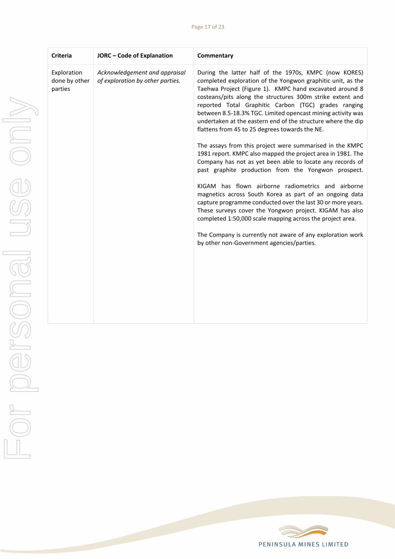
Exploration done by other parties
Acknowledgement and appraisal of exploration by other parties.
During the latter half of the 1970s, KMPC (now KORES) completed exploration of the Yongwon graphitic unit, as the Taehwa Project (Figure 1). KMPC hand excavated around 8 costeans/pits along the structures 300m strike extent and reported Total Graphitic Carbon (TGC) grades ranging between 8.5-18.3% TGC. Limited opencast mining activity was undertaken at the eastern end of the structure where the dip flattens from 45 to 25 degrees towards the NE. The assays from this project were summarised in the KMPC 1981 report. KMPC also mapped the project area in 1981. The Company has not as yet been able to locate any records of past graphite production from the Yongwon prospect. KIGAM has flown airborne radiometrics and airborne magnetics across South Korea as part of an ongoing data capture programme conducted over the last 30 or more years. These surveys cover the Yongwon project. KIGAM has also completed 1:50,000 scale mapping across the project area. The Company is currently not aware of any exploration work by other non-Government agencies/parties.
For
per
sona
l use
onl
y

Page 18 of 23
Criteria JORC – Code of Explanation Commentary
Geology Deposit type, geological setting and style of mineralisation.
The Yongwon graphite deposit was formed as a result of regional and possible contact metamorphism of carbonaceous material hosted within the locally banded Precambrian gneiss. The coarse flake graphite is hosted in a quartz, K-feldspar, ± muscovite schist-sandstone / quartzite horizon that is locally interbedded with more schistose layers with an observed increased clay mineral content. The Proterozoic basement gneiss has been locally intruded by Mesozoic aged granites and porphyry. The MLEM survey has defined a highly conductive graphitic schist that strongly contrasts with surrounding non-conductive country rock, composed predominately of biotite gneiss, porphyry and granite. The sharp cut-off along the southern and western margins of the EM anomaly is due to the Mesozoic intrusives cutting through the Proterozoic basement sequence that hosts the graphite mineralisation at Yongwon. The MLEM survey coupled with surface mapping of the sub-cropping and outcropping graphitic schist has defined a structure that dips at 45° to the northeast (NE) and flattens to 25° NE along strike to the southeast (SE).
For
per
sona
l use
onl
y

Page 19 of 23
Criteria JORC – Code of Explanation Commentary
Drill hole information
A summary of all information material to the understanding of the exploration results including a tabulation of the following information for all Material drill holes: • easting and northing of the drill hole collar • elevation or RL (Reduce Level) – elevation above sea level in metres) of the drill hole collar • dip and azimuth of the hole • down hole length and interception depth • hole length
All channel sampling sample results and sample location details are summarised in Appendix 1.
No drilling has been completed at Yongwon. The proposed drilling positions are shown on Figure 4. However, these may change so this proposal is only a general guide as to where drilling may take place.
As there is no drilling, there are no results (exploration results) related to any drilling and as such, under 5.7.2 – the position of the proposed drill holes is not material to the understanding of the exploration results.
If the exclusion of this information is justified on the basis that the information is not Material and this exclusion does not detract from the understanding of the report, the Competent Person should clearly explain why this is the case.
No material information has been excluded from this release.
As there is no drilling, there are no results (exploration results) related to any drilling.
Data aggregation methods
In reporting Exploration Results, weighting averaging techniques, maximum and/or minimum grade truncations (eg cutting of high grades) and cut-off grades are usually Material and should be stated.
No data has been cut or truncated.
For
per
sona
l use
onl
y

Page 20 of 23
Criteria JORC – Code of Explanation Commentary
Where aggregate intercepts incorporate short lengths of high grade results and longer lengths of low grade results, the procedure used for such aggregation should be stated and some typical examples of such aggregations should be shown in detail.
All assay values reported are raw assays and none of the data values have been cut or truncated. Channels length weighted averages have been calculated for the full breadth of the sampled interval. In each case, the results of the analysis for each individual sampled interval has been reported.
The assumptions used for any reporting of metal equivalent values should be clearly stated.
No metal equivalent values have been reported.
Relationship between mineralisation widths and intercept lengths
These relationships are particularly important in the reporting of Exploration Results.
The channel sampled intersection approximates ~130% of true width due to the moderately dipping graphitic unit. No tonnage or Mineral Resource potential has been commented on in this release.
If the geometry of the mineralisation with respect to the drill hole angle is known, its nature should be reported.
No drilling has been undertaken by the Company and no drilling results have been reported or commented upon in this release. Drilling referenced in this release is proposed only.
If it is not known and only the down hole lengths are reported, there should be a clear statement to this effect (e.g. ‘down hole length, true width not known’).
No drilling has been undertaken and no drill assay results have been reported or commented upon. Drilling referenced in this release is proposed only.
Diagrams Appropriate maps and sections (with scales) and tabulations of intercepts should be included for any significant discovery being reported. These should include, but not be limited to a plan view of drill hole collar locations and appropriate sectional views.
Figures 1 shows the location of the channel sampling completed at Yongwon and previous releases show previous resultsD1, D2, D3. Figure 4 shows proposed drill hole locations in isometric view. No drilling has yet been undertaken at the Yongwon Project and no drill assay results have been reported or commented upon. Drilling referenced in this release is proposed only. F
or p
erso
nal u
se o
nly

Page 21 of 23
Criteria JORC – Code of Explanation Commentary
Balanced reporting
Where comprehensive reporting of all Exploration Results is not practicable, representative reporting of both low and high grades and/or widths should be practiced to avoid misleading reporting of Exploration Results.
All assay values and sample location details have been reported and are summarised in Appendix 1. The sample location details are shown in Figure 1. Previous results were included in earlier announcements and can be reviewed by the reader for comparative purposesD1-D3.
Other substantive exploration data
Other exploration data, if meaningful and material, should be reported including (but not limited to): geological observations; geophysical survey results; geochemical survey results; bulk samples – size and method of treatment; metallurgical test results; bulk density, groundwater, geotechnical and rock characteristics; potential deleterious or contaminating substances.
All data considered relevant and material have been included and commented upon in this announcement or included in earlier announcementsD1-D3.
Further work The nature and scale of planned further work (e.g. tests for lateral extensions or depth extensions or large-scale step-out drilling).
The high-grade of the concentrate produced from the Yongwon graphitic material indicates suitability for further down-stream processing including micronisation then spheronization to produce a spherical graphite concentrate for final purification and coating prior to lithium-ion battery anode production. Testing to determine spheronization potential of the Yongwon graphite concentrate will commence immediately so that a suitable sample-product can be produced for discussions with potential offtake partners in South Korea and North Asia generally. Channel sampling will continue in the upcoming field season utilising existing KMPC trenches. In addition, an application will be filed with the Local Government forest office to excavate 3 more costeans on the 3 western most 80m spaced drill sections. The aim being to test the graphitic unit at surface across the entire width of the subcropping to outcropping structure. This work will commence once the snow melts and access is again possible. This work is currently planned for March and/or early in the second quarter. This work will produce resource quality channel data and aims to determine the full breadth of the Yongwon structure at surface along at least 300m of the known strike through nominally 20m spaced trenches.
For
per
sona
l use
onl
y

Page 22 of 23
Criteria JORC – Code of Explanation Commentary
A drilling programme has been planned to test the graphitic unit on 80m spaced sections with the objective of defining an Indicated Resource. The initial four cross sections will include a planned 16-hole diamond drilling programme from 9 drill-pads (see Figure 4) for approximately 1,100m. In addition, a submission has been made to the Korean Resources Corporation (KORES). KORES is a Korean Government agency who provide funding for the exploration and development of mineral resources by Korean registered companies. The application for drill funding support is for up to 7 additional holes on the eastern side of this initial programme. An application has also been filed with the Local Government for forest access approval. It is anticipated that drilling consent and access approval will be achieved before the field season commences in mid-March 2017.
Diagrams clearly highlighting the areas of possible extensions, including the main geological interpretations and future drilling areas, provided this information is not commercially sensitive.
The included Figure 1 shows the mapped location of the graphite seams at Yongwon and the EM geophysical conductor projected to surface showing possible extensions to the graphitic unit at depth and down plunge. Figure 4 shows the graphitic unit, modelled EM conductor and the proposed drilling locations targeting the graphitic unit at depth. At Yongwon, the structure remains open to the east where thick soil cover obscures any rock outcrop and at depth (Figures 1 and 4).
For
per
sona
l use
onl
y

Page 23 of 23
Appendix 1: Location and Results for the channel sampling at the Yongwon Graphite Project
*Channel ID
Sample ID
Easting Northing RL (m)
From To Interval
(m)
True Width
(m)
TGC %
TC% TIC% TOC% S% UTM 52N UTM 52N
YCH0001 YC0001 383,752 4,093,357 512 0 0.7 0.7 0.69 8.1 8.5 0.3 <0.1 0.2
YCH0001 YC0002 383,753 4,093,358 512 0.7 1.35 0.65 0.65 6.6 6.9 0.2 <0.1 0.1
YCH0001 YC0003 383,753 4,093,358 512 1.35 1.95 0.6 0.5 13.6 14.6 0.4 0.7 0.2
YCH0001 YC0004 383,753 4,093,358 513 1.95 2.65 0.7 0.6 3.5 4 0.2 0.3 0.1
YCH0001 YC0005 383,754 4,093,359 513 2.65 3.65 1 0.87 13.6 14.3 0.4 0.3 0.2
YCH0001 YC0006 383,755 4,093,359 513 3.65 4.65 1 0.84 18.1 18.7 0.2 0.4 0.1
YCH0002 YC0007 383,755 4,093,360 514 0 0.2 0.2 0.13 16.5 17.3 0.6 0.2 0.1
YCH0002 YC0008 383,755 4,093,360 514 0.2 0.45 0.25 0.14 17.5 18.1 0.6 <0.1 0.1
YCH0002 YC0009 383,755 4,093,360 514 0.45 1.25 0.8 0.51 7.7 8.3 0.2 0.4 <0.1
YCH0003 YC0010 383,756 4,093,361 514 1.25 2.05 0.8 0.62 0.7 1.3 <0.1 0.5 <0.1
YCH0004 YC0011 383,756 4,093,362 514 2.05 2.85 0.8 0.41 15.3 15.7 0.3 0.1 0.1
YCH0004 YC0012 383,756 4,093,363 514 2.85 3.75 0.9 0.65 18.5 19.3 <0.1 0.7 0.2
YCH0005 YC0014 383,756 4,093,363 514 3.75 4.55 0.8 0.45 16.6 17.5 0.2 0.7 0.2
YCH0006 YC0015 383,757 4,093,364 514 4.55 5.05 0.5 0.47 9.3 10 0.4 0.3 0.2
Total 9.7m 7.53 11.7
*Multiple Channel IDs reflect the change in direction of the sawn channel.
TGC Total Graphitic Carbon TC Total Carbon TIC Inorganic Carbon TOC Organic Carbon S Sulphur
For
per
sona
l use
onl
y