excerpt of sedra/smith chapter 1: signals and … of sedra/smith chapter 1: signals and amplifier...
TRANSCRIPT
INF3410 — Fall 2016
Excerpt of Sedra/Smith Chapter 1: Signals andAmplifier Concept

Content
Signals and Spectra
Amplifiers
Excerpt of Sedra/Smith Chapter 1: Signals and AmplifierConcept 2

Content
Signals and Spectra
Amplifiers
Excerpt of Sedra/Smith Chapter 1: Signals and AmplifierConcept 3

Book Sections Covered
1.1-1.3
Excerpt of Sedra/Smith Chapter 1: Signals and AmplifierConcept 4

Signal Sources
Two equivalent models of signal sources (e.g. a sensoror other transducer): a) is called the The Thévenin formand b) the Norton form. Note: Outputresistance RS isthe same in both models while vS(t) = iS(t)RS. A moregeneral model would consider an outputimpedancerather than just a resistance ...Excerpt of Sedra/Smith Chapter 1: Signals and Amplifier
Concept 5
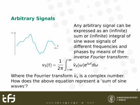
Arbitrary SignalsAny arbitrary signal can beexpressed as an (infinite)sum or (infinite) integral ofsine wave signals ofdifferent frequencies andphases by means of theinverse Fourier transform:
vS(t) =1
2π
∫ ∞
−∞v̂s(ω)eiωtdω
Where the Fourrier transform v̂s is a complex number.How does the above equation represent a ’sum of sinewaves’?Excerpt of Sedra/Smith Chapter 1: Signals and Amplifier
Concept 6
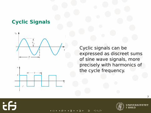
Cyclic Signals
Cyclic signals can beexpressed as discreet sumsof sine wave signals, moreprecisely with harmonics ofthe cycle frequency.
Excerpt of Sedra/Smith Chapter 1: Signals and AmplifierConcept 7

Example: Approximating Square Wave
Here is how a square wavecan be approximated withthe sum of 3 sine waves.
v(t) =4V
π
�
sinω0t +1
3sin3ω0t +
1
5sin5ω0t + ...
�
(1.2)
Excerpt of Sedra/Smith Chapter 1: Signals and AmplifierConcept 8
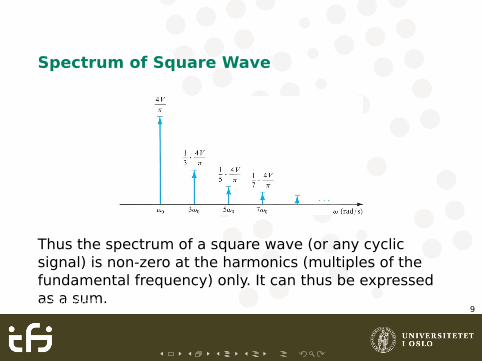
Spectrum of Square Wave
Thus the spectrum of a square wave (or any cyclicsignal) is non-zero at the harmonics (multiples of thefundamental frequency) only. It can thus be expressedas a sum.Excerpt of Sedra/Smith Chapter 1: Signals and Amplifier
Concept 9

Spectrum of Arbitrary Function
whereas the spectrum of a non-cyclic function can benon-zero for any frequency, e.g. the function in figure1.3.
Excerpt of Sedra/Smith Chapter 1: Signals and AmplifierConcept 10

Discrete Time/Sampled
Excerpt of Sedra/Smith Chapter 1: Signals and AmplifierConcept 11

Discrete Value/Digital
(for example binary)
Excerpt of Sedra/Smith Chapter 1: Signals and AmplifierConcept 12

ADC
Excerpt of Sedra/Smith Chapter 1: Signals and AmplifierConcept 13

Content
Signals and Spectra
AmplifiersFrequency Response
Excerpt of Sedra/Smith Chapter 1: Signals and AmplifierConcept 14

Book Sections Covered
1.4-1.6
Excerpt of Sedra/Smith Chapter 1: Signals and AmplifierConcept 15
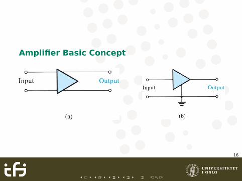
Amplifier Basic Concept
Excerpt of Sedra/Smith Chapter 1: Signals and AmplifierConcept 16

Example: Voltage Amplifier with LoadResistance
Excerpt of Sedra/Smith Chapter 1: Signals and AmplifierConcept 17

Gain in Decibels
Av =vO
vI
Ap =pO
pL=
vOiO
vIiI= AvAi
Ap,dB = 10 log10 Ap [dB]
Av,dB = 20 log10 Av [dB]
Excerpt of Sedra/Smith Chapter 1: Signals and AmplifierConcept 18

Increasing Signal Power
(and thus in need of a power supply)
η =PL
Pdc× 100 (1.10)
Excerpt of Sedra/Smith Chapter 1: Signals and AmplifierConcept 19

Non-Ideal Behaviour (1/many)
Linear range:
L−
Av≤ vI ≤
L+
Av
(near Fig. 1.14)
Excerpt of Sedra/Smith Chapter 1: Signals and AmplifierConcept 20
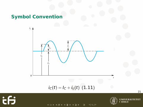
Symbol Convention
iC(t) = IC + ic(t) (1.11)Excerpt of Sedra/Smith Chapter 1: Signals and AmplifierConcept 21
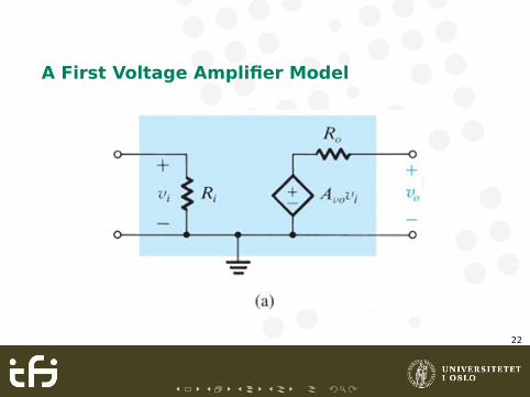
A First Voltage Amplifier Model
Excerpt of Sedra/Smith Chapter 1: Signals and AmplifierConcept 22
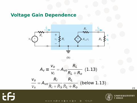
Voltage Gain Dependence
Av ≡vo
vi= Avo
RL
RL +Ro(1.13)
vo
vs= Avo
Ri
Ri +RS
RL
RL +Ro(below 1.13)
Excerpt of Sedra/Smith Chapter 1: Signals and AmplifierConcept 23

Example: Cascaded Amplifiers
vo
vs=
Ri1
Ri1 +RSAvo1
Ri2
Ri2 +Ro1Avo2
Ri3
Ri3 +Ro2...AvoN
RL
RL +RoN
Excerpt of Sedra/Smith Chapter 1: Signals and AmplifierConcept 24
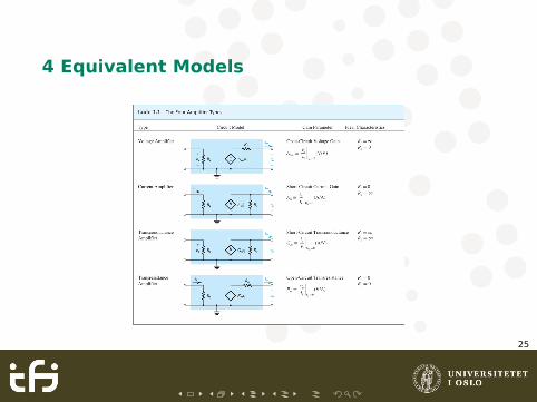
4 Equivalent Models
Excerpt of Sedra/Smith Chapter 1: Signals and AmplifierConcept 25

Determining Ri and Ro
Excerpt of Sedra/Smith Chapter 1: Signals and AmplifierConcept 26
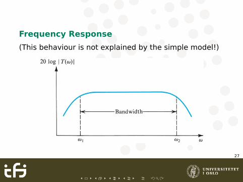
Frequency Response
(This behaviour is not explained by the simple model!)
Excerpt of Sedra/Smith Chapter 1: Signals and AmplifierConcept 27

Linear Amplifier
Linear here means that there is no distortion of a fixedfrequency sinusoid. An amplifier composed of but linearelements will behave like that, including somewhatmore complicated models than our first purely resistivemodel ...
Excerpt of Sedra/Smith Chapter 1: Signals and AmplifierConcept 28

Single Time Constant Networks
When the input voltage source provides a signal theSTC network is a filter with a specific transfer function,i.e. a frequency dependent complex number.Excerpt of Sedra/Smith Chapter 1: Signals and Amplifier
Concept 29
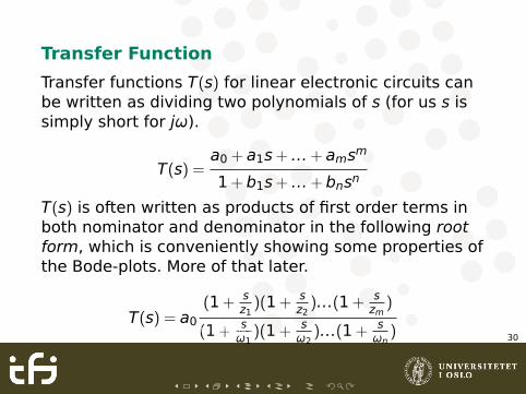
Transfer Function
Transfer functions T(s) for linear electronic circuits canbe written as dividing two polynomials of s (for us s issimply short for jω).
T(s) =a0 + a1s+ ...+ amsm
1+ b1s+ ...+ bnsn
T(s) is often written as products of first order terms inboth nominator and denominator in the following rootform, which is conveniently showing some properties ofthe Bode-plots. More of that later.
T(s) = a0
(1+ sz1)(1+ s
z2)...(1+ s
zm)
(1+ sω1
)(1+ sω2
)...(1+ sωn
)Excerpt of Sedra/Smith Chapter 1: Signals and AmplifierConcept 30
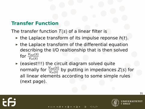
Transfer Function
The transfer function T(s) of a linear filter isÉ the Laplace transform of its impulse reponse h(t).É the Laplace transform of the differential equation
describing the I/O realtionship that is then solvedfor Vout(s)
Vin(s)
É (easiest!!!) the circuit diagram solved quitenormally for Vout(s)
Vin(s)by putting in impedances Z(s) for
all linear elements according to some simple rules(next page).
Excerpt of Sedra/Smith Chapter 1: Signals and AmplifierConcept 31
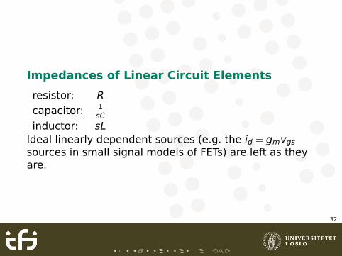
Impedances of Linear Circuit Elements
resistor: R
capacitor: 1sC
inductor: sLIdeal linearly dependent sources (e.g. the id = gmvgs
sources in small signal models of FETs) are left as theyare.
Excerpt of Sedra/Smith Chapter 1: Signals and AmplifierConcept 32

Single Time Constant Transfer Functions
Excerpt of Sedra/Smith Chapter 1: Signals and AmplifierConcept 33
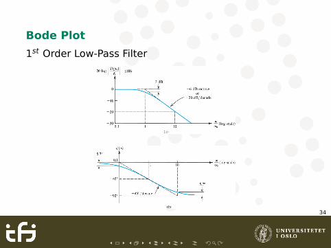
Bode Plot
1st Order Low-Pass Filter
Excerpt of Sedra/Smith Chapter 1: Signals and AmplifierConcept 34
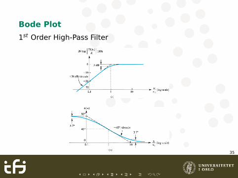
Bode Plot
1st Order High-Pass Filter
Excerpt of Sedra/Smith Chapter 1: Signals and AmplifierConcept 35

Example
Excerpt of Sedra/Smith Chapter 1: Signals and AmplifierConcept 36

Characterizing Amplifiers by TransferCharacteristics
Excerpt of Sedra/Smith Chapter 1: Signals and AmplifierConcept 37

Capacitively Coupled Two Stage Amplifiers
Excerpt of Sedra/Smith Chapter 1: Signals and AmplifierConcept 38