execution & qualification of heating, ventilation and air ... · heating, ventilation and...
TRANSCRIPT
Execution & Qualification of Heating, Ventilation and Air Conditioning
System
Himmat Singh*, Jatin Vidja, Mohit Agrawal and Rakesh Kr Sharma,
School of Pharmacy, Suresh Gyan Vihar University, Jaipur 302017 (Rajasthan).
Email: [email protected]
Address for Correspondence:
Mr. Himmat Singh
Assistant Professor
Department of Pharmaceutics
Gyan vihar School of pharmacy
Suresh Gyan vihar University
Mahal,Jagatpura
Jaipur (Raj.)
Email id:[email protected]
Abstract: Qualification is an integral part of quality assurance. Qualification is
systematic approach to gathering and analyzing sufficient data that will give reasonable
assurance (documented evidence), based on scientific judgment that a system when operating
within specified parameters will give accepted results. There should be proper preparation and
planning before qualification is performed. There should be a specific programme for
qualification activities. Qualification should be performed in a structured way according to the
documented procedures and protocols. Qualification should be performed for new premises,
equipment, utilities and systems, at periodic intervals, when major changes have been made.
Qualification establishes and provides documentary evidence that:
(a) The premises, supporting utilities, equipment and processes have been designed in
accordance with the requirements for GMP (Design Qualification).
(b) The premises, supporting utilities and equipment have been built and installed in
compliance with their design specifications (Installation Qualification).
(c) The premises, supporting utilities and equipment operate in accordance with their design
specifications (Operational Qualification).
(d) A specific process will consistently produce a product meeting its predetermined
specifications and quality attributes (Performance Qualification).
This industrial aspect includes importance, benefit, Operational stage and control variables and
sampling plan related to HVAC system.
Key Words: Qualification, GMP, HVAC system & Control Variables.
1. Introduction
Qualification is the planning, carrying out and recording of tests on equipment and a system,
which forms part of the validated process, to demonstrate that it will perform as intended. In
accordance with Good Manufacturing Practices, each pharmaceutical company should
identify what qualification work is required to prove that the critical aspects of their particular
operation are controlled. The key elements of a qualification and validation programme of a
company should be clearly defined and documented.1
The Basic Principles for Qualification: Equipment is correctly installed in accordance with
an installation plan. Requirements for calibration, maintenance and cleaning are covered in
approved SOP's. Tests are conducted to assure that equipment is operating correctly, under
normal and "worst case" conditions. Operator training requirements pertaining to new
equipment should be conducted and documented. Any aspect of operation, including
significant changes to the premises, facilities, equipment or processes, which may affect the
quality of the product, directly or indirectly, should be qualified and validated. 2
For new utility, following activities carried out to demonstrate the compliance of
equipment to design, characteristics and capabilities to meet the intended purpose.
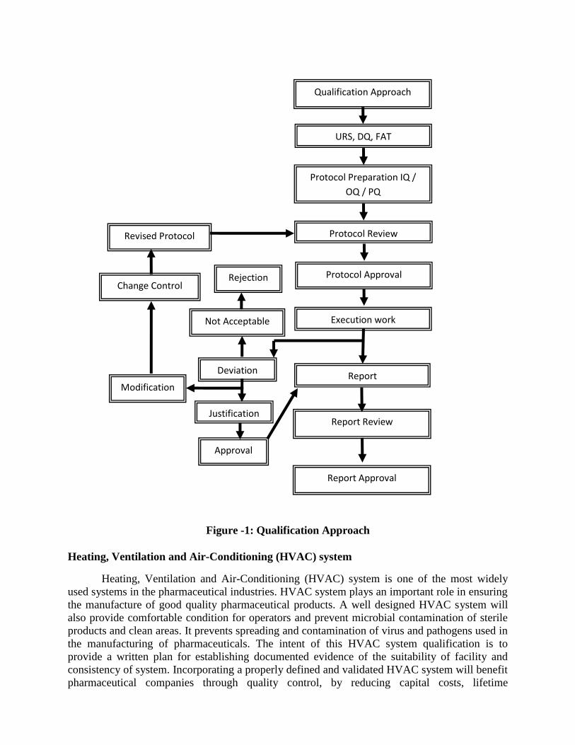
Figure -1: Qualification Approach
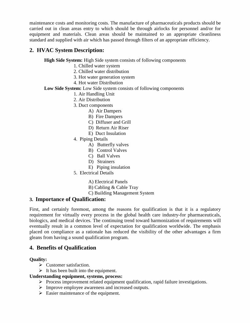
Heating, Ventilation and Air-Conditioning (HVAC) system
Heating, Ventilation and Air-Conditioning (HVAC) system is one of the most widely
used systems in the pharmaceutical industries. HVAC system plays an important role in ensuring
the manufacture of good quality pharmaceutical products. A well designed HVAC system will
also provide comfortable condition for operators and prevent microbial contamination of sterile
products and clean areas. It prevents spreading and contamination of virus and pathogens used in
the manufacturing of pharmaceuticals. The intent of this HVAC system qualification is to
provide a written plan for establishing documented evidence of the suitability of facility and
consistency of system. Incorporating a properly defined and validated HVAC system will benefit
pharmaceutical companies through quality control, by reducing capital costs, lifetime
Qualification Approach
URS, DQ, FAT
Protocol Preparation IQ /
OQ / PQ
Protocol Review Revised Protocol
Change Control
Modification
Rejection Protocol Approval
Execution work
Deviation Report
Report Review
Report Approval
Justification
Approval
Not Acceptable
maintenance costs and monitoring costs. The manufacture of pharmaceuticals products should be
carried out in clean areas entry to which should be through airlocks for personnel and/or for
equipment and materials. Clean areas should be maintained to an appropriate cleanliness
standard and supplied with air which has passed through filters of an appropriate efficiency.
2. HVAC System Description:
High Side System: High Side system consists of following components
1. Chilled water system
2. Chilled water distribution
3. Hot water generation system
4. Hot water Distribution
Low Side System: Low Side system consists of following components
1. Air Handling Unit
2. Air Distribution
3. Duct components
A) Air Dampers
B) Fire Dampers
C) Diffuser and Grill
D) Return Air Riser
E) Duct Insulation
4. Piping Details
A) Butterfly valves
B) Control Valves
C) Ball Valves
D) Strainers
E) Piping insulation
5. Electrical Details
A) Electrical Panels
B) Cabling & Cable Tray
C) Building Management System
3. Importance of Qualification:
First, and certainly foremost, among the reasons for qualification is that it is a regulatory
requirement for virtually every process in the global health care industry-for pharmaceuticals,
biologics, and medical devices. The continuing trend toward harmonization of requirements will
eventually result in a common level of expectation for qualification worldwide. The emphasis
placed on compliance as a rationale has reduced the visibility of the other advantages a firm
gleans from having a sound qualification program.
4. Benefits of Qualification
Quality: Customer satisfaction.
It has been built into the equipment.
Understanding equipment, systems, process: Process improvement related equipment qualification, rapid failure investigations.
Improve employee awareness and increased outputs.
Easier maintenance of the equipment.
Fewer complaints about process related failures.
More rapid and reliable startup of new equipment.
More rapid automation.
Regulatory benefits:
Successful inspections.
Approved products.
5. Stage of Qualification
There are different stages of qualification. These include:
Design Qualification
Design qualification should provide documented evidence that the design specifications were
met or quality is built into the design of facilities and operations.
Installation Qualification
Installation qualification should provide documented evidence that the installation was complete
and satisfactory. The purchase specifications, drawings, and vendor details should be verified
during installation qualification.
Operational Qualification
Operational qualification should provide documented evidence that utilities, systems or
equipment and all its components operate in accordance with operational specifications. Tests
should be designed to demonstrate operation over the normal operating range as well as at the
limits of its operating conditions (e.g. including worst case conditions).
Performance Qualification
Performance qualification should provide documented evidence that utilities, systems or
equipment and all its components can consistently perform in accordance with its specifications
under routine use. Test results should be collected over a period of time to prove consistency.
6. Methodology for HVAC Qualification
6.1 Methodology of execution:
Qualification exercise was performed by the external service provider and by validation
team (where appropriate).
The instruments/ equipments used for performing the tests were under a valid calibration
period.
The qualification activities were performed according to the plan and approved protocol.
The activities were performed in the presence of representatives from engineering
department to witness the activity and verified by the representatives from QA.
After completion of respective activities, the raw data reviewed by the QA to ensure
compliance with the acceptance criteria. A copy of the raw data is retained by the QA.
After completion of the review process, QA compiles the obtained certificates and
prepare a conclusion report for the activities performed.
The conclusion reports reviewed by engineering team, and authorized by Head –QA.
6.2 Methodology for Installation Qualification
Installation qualification consist of following check point
Reason for installation qualification
Brief overview of the equipment / instrument / system
Equipment details
Physical verification on receipt
Physical verification of the area
Verification of material of construction and surface finish
Identification of major components and accessories
Verification of specifications of major components
Identification of instruments requiring calibration or testing
Verification of required change parts
Identification and verification of supporting utilities
Identification of standard operating procedures
Deficiency and corrective action report
6.3 Methodology for Operational Qualification
The objective of the operational qualification was to establish documented evidence that
the Air Handling Unit was operated within tolerances and limits. This operational qualification is
applicable to Air Handling Unit and also covers equipment operation, objective, scope,
responsibility, operational test, safety feature, acceptance criteria, equipment description, and
calibration of equipments, functional test plan at rest.
Operational Qualification consists of the following check points and test:
1. Calibration of instruments
2. Electrical panel testing
3. Verification of Motor operation in no load / load condition when belt was disconnected
4. Verification of all the key functionalities of the control panel
5. Verification of safety features of the system
6. AHU Panel leak test
7. AHU drains verification
8. AHU blow down and leak test
9. System Balancing
6.4 Methodology for Performance Qualification
6.4.1 Air flow velocity test and calculation of Air changes per hour8, 15
Objective:
The purpose of this test was to measure air flow velocity and its uniformity across the
filter, and supply air flow rate in clean room & clean zones. Measurement of supply air flow rate
was carried out to ascertain the air volume supplied to the clean installation per unit of time, and
this value was used to determine the air changes per unit of time.
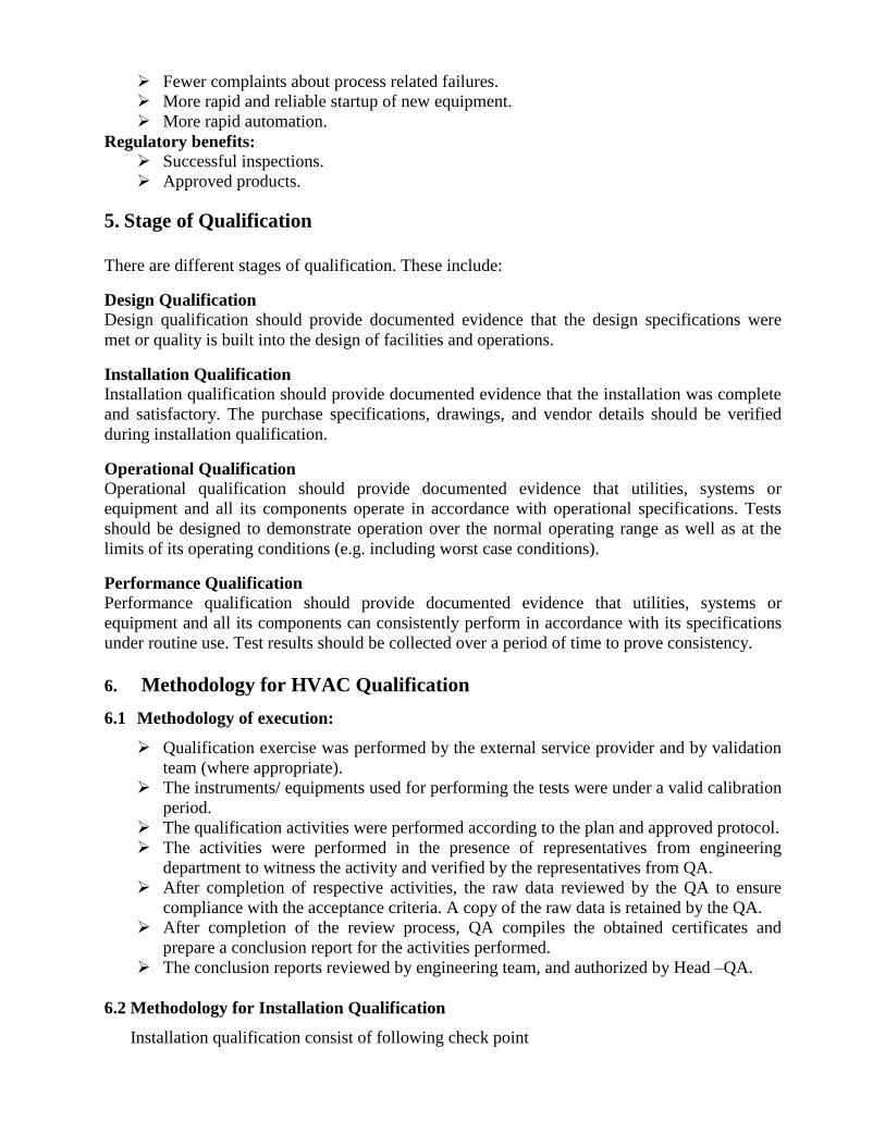
Instrument used Acceptance criteria Frequency
1. Van type
anemometer.
2. Thermal (Hot
wire)
anemometer.
For ACPH:
NLT 40 in class 100A &
Class 100B (1000)
NLT 30 in Class 10,000
NLT 20 in Class 100,000
ISO 5 & 7 areas ISO 8 areas
6 months ± 20 days
-Replacement of
HEPA filters
-Any modifications
in the AHU
- As required on
case to case basis
12 months ± 20
days
- Replacement of
HEPA filters
- Any modifications
in the AHU
- As required on
case to case basis
Procedure: For plenum HEPA
Readings were taken in a plane perpendicular at a distance of approximately 75-150 mm
from the HEPA filter face.
The air velocity of the unit was measured in FPM.
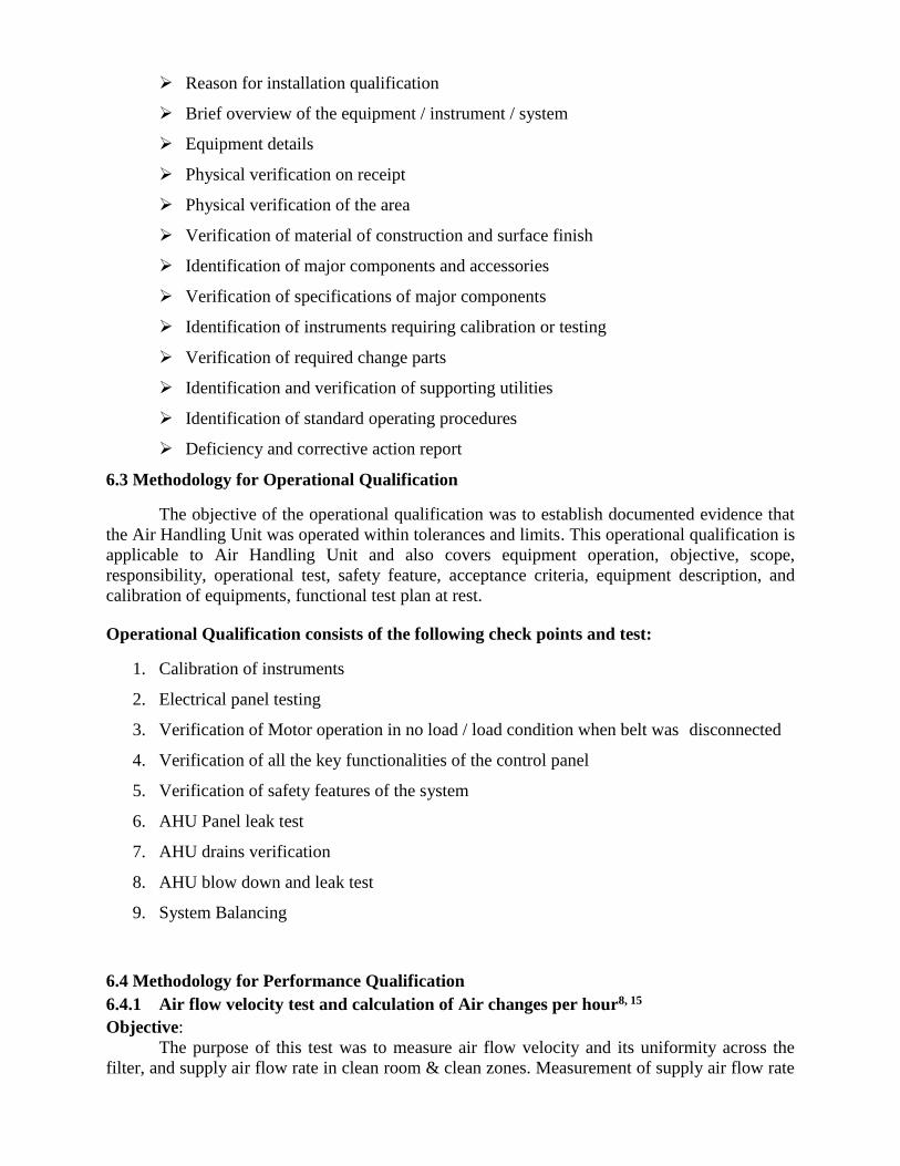
Measured the air flow velocity from the four corners and center of filter (as indicated in
figure-III) and obtain an average reading. Obtain the average velocity of all the HEPA
filters of the plenum in FPM and calculate the total no of CFM supplied by the unit using
the following formula.
Total CFM = Average velocity in FPM x No. of filters x surface area of the filters (in ft2)
Figure-III: Sampling location for air flow measurement
For terminal HEPA filters & diffusers: Readings were taken in a plane perpendicular to and at a distance of approx. 50-100 mm
downstream of the HEPA parallel face.
Air velocity of the unit was measured in FPM.
Measured the air flow velocity from the four corners and centre of the filter (as in figure-
III) and calculate the average velocity in FPM.
Determined the CFM of air flowing out of each filter by using the formula.
Air flow in CFM = Average velocity in FPM x Surface area of the filter (in ft2)
Calculate the total air flow in CFM from all the supply filters available in the room by
adding the CFM values obtained from supply grills.
Calculate the no. of air changes per hour inside each room by using the formula,
No. of air changes/hour = Total CFM x 60
Room volume in ft3
Or
No. of air changes/hour = Total CFM x 1.7
Room volume in m3
6.4.2 Filter integrity test15
Objective:
V1
V5
V2
V4 V3
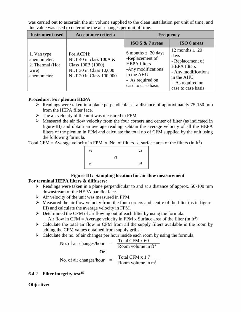
This test was performed to confirm that the filter system was properly installed and the
leaks have not developed during use. The test verifies the absence of leakages, relevant to the
cleanliness performance of the installation. This test was applicable for HEPA filters having
efficiency of 99.97% and above only.
Instrument
used Acceptance criteria Frequency
Aerosol
generator &
Linear Aerosol
Photometer
PAO (Poly Alpha Olefin)
penetration from the
downstream air of the
HEPA filters should not be
more than 0.01% of the
upstream challenge aerosol
concentration.
ISO 5 & 7 areas ISO 8 areas
6 months ± 20
days
- Replacement of
HEPA filters
-Any modifications
in the AHU
- As required on
case to case basis
24 months ± 30
days
- Replacement of
HEPA filters
-Any modifications
in the AHU
- As required on case
to case basis
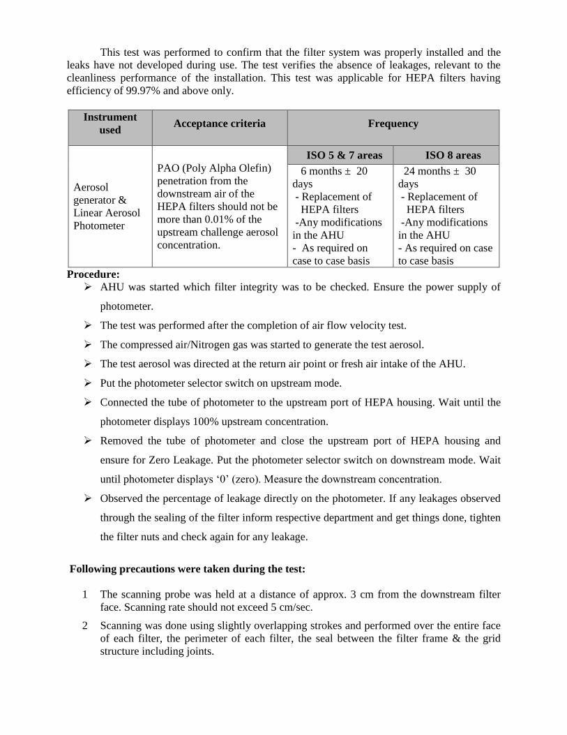
Procedure:
AHU was started which filter integrity was to be checked. Ensure the power supply of
photometer.
The test was performed after the completion of air flow velocity test.
The compressed air/Nitrogen gas was started to generate the test aerosol.
The test aerosol was directed at the return air point or fresh air intake of the AHU.
Put the photometer selector switch on upstream mode.
Connected the tube of photometer to the upstream port of HEPA housing. Wait until the
photometer displays 100% upstream concentration.
Removed the tube of photometer and close the upstream port of HEPA housing and
ensure for Zero Leakage. Put the photometer selector switch on downstream mode. Wait
until photometer displays ‘0’ (zero). Measure the downstream concentration.
Observed the percentage of leakage directly on the photometer. If any leakages observed
through the sealing of the filter inform respective department and get things done, tighten
the filter nuts and check again for any leakage.
Following precautions were taken during the test:
1 The scanning probe was held at a distance of approx. 3 cm from the downstream filter
face. Scanning rate should not exceed 5 cm/sec.
2 Scanning was done using slightly overlapping strokes and performed over the entire face
of each filter, the perimeter of each filter, the seal between the filter frame & the grid
structure including joints.
3 Observe the penetration of PAO particles across the HEPA filter on the display of
photometer and record the value. Carry out the same for each HEPA filters of AHU
system.
4 If the display shows value greater than the 0.01% considers it as leakages. Sealing of the
leakages shall be carried out with sealant. If leakage is more than 1% of the total filter
areas, replace the filter with new filter.
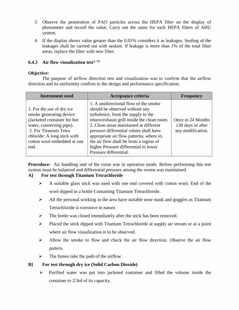
6.4.3 Air flow visualization test1, 15
Objective:
The purpose of airflow direction test and visualization was to confirm that the airflow
direction and its uniformity confirm to the design and performance specification.
Instrument used Acceptance criteria Frequency
1. For the use of dry ice
smoke generating device
(Jacketed container for hot
water, connecting pipe).
2. For Titanium Tetra
chloride: A long stick with
cotton wool embedded at one
end.
1. A unidirectional flow of the smoke
should be observed without any
turbulence, from the supply to the
return/exhaust grill inside the clean room.
2. Clean areas maintained at different
pressure differential values shall have
appropriate air flow patterns, where in,
the air flow shall be from a region of
higher Pressure differential to lower
Pressure differential.
Once in 24 Months
±30 days or after
any modification.
Procedure: Air handling unit of the room was in operation mode. Before performing this test
system must be balanced and differential pressure among the rooms was maintained.
A] For test through Titanium Tetrachloride
A suitable glass stick was used with one end covered with cotton wool. End of the
wool dipped in a bottle Containing Titanium Tetrachloride.
All the personal working in the area have suitable nose mask and goggles as Titanium
Tetrachloride is corrosive in nature.
The bottle was closed immediately after the stick has been removed.
Placed the stick dipped with Titanium Tetrachloride at supply air stream or at a point
where air flow visualization is to be observed.
Allow the smoke to flow and check the air flow direction. Observe the air flow
pattern.
The fumes take the path of the airflow.
B] For test through dry ice (Solid Carbon Dioxide)
Purified water was put into jacketed container and filled the volume inside the
container to 2/3rd of its capacity.

The power supply was connected with the hot water-jacket and allow the water to
boil.
Dry ice was manually put into the water and observed for the dense smoke to come
out of the pipe.
The pipe was hold at supply air stream or at a point where air flow visualization is to
be observed.
The flow (passage) of the smoke was observed and also observed the air flow pattern.
6.4.4 Temperature, %RH monitoring test.
Objective: The purpose of this test was to demonstrate the capability of the installed air-handling
system to maintain the air temperature, %RH within the acceptance criteria
Instrument used Acceptance criteria Frequency
Temperature,
% RH
Psychrometer/
Hygrometer
The temperature of
specified locations
shall be 23±2 C
1. This test is performed only for the
new installation or any modifications
done to t he existing installations at
the define frequency
2. This test is not a part of periodical
validation exercise.
Test Procedure:
1. HVAC system was run for 24 hours before the test to stabilize the room and all the doors
were properly closed.
2. The temperature and relative humidity were measured with the help of sling
psychrometer.
3. Reading were recorded for a period of eight hours with interval of every one hour for 3
days at rest condition and & 7 days for at working condition.
6.4.5 Room differential pressure checks test:
Objective:
To check that the differential pressures between room and atmosphere and to verify that
the readings are within designed values.
Instrument used Acceptance criteria Frequency
Differential
Pressure
Magnehelic
gauge /
Manometer
The Relative Humidity in
each room/area shall be
50±5%
1. This test is performed only for the
new installation or any modifications
done to the existing installations at the
define frequency
2. This test is not a part of periodical
validation exercise.
Acceptance criteria:
The relative room differential pressures between room and atmosphere shall be lass then
30 Pa of the designed values.
Test Procedure:
1. An air-handling unit was continuously operated.
2. Unexpected changes in air pressure was avoid to establish a baseline, all doors in the
facility were closed and no man movement to be allowed during observations.
3. The differential pressure of the room was recorded from the Magnehelic gauge.
4. Readings were taken for a period of eight hours with an interval of every one hour for 3
days at rest condition and 7 days for at working condition.
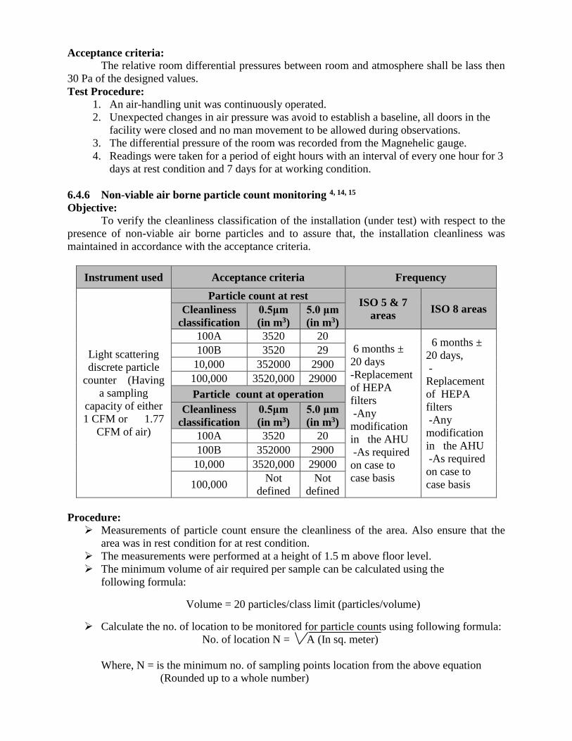
6.4.6 Non-viable air borne particle count monitoring 4, 14, 15
Objective:
To verify the cleanliness classification of the installation (under test) with respect to the
presence of non-viable air borne particles and to assure that, the installation cleanliness was
maintained in accordance with the acceptance criteria.
Instrument used Acceptance criteria Frequency
Light scattering
discrete particle
counter (Having
a sampling
capacity of either
1 CFM or 1.77
CFM of air)
Particle count at rest ISO 5 & 7
areas ISO 8 areas Cleanliness
classification
0.5μm
(in m3)
5.0 μm
(in m3)
100A 3520 20 6 months ±
20 days
-Replacement
of HEPA
filters
-Any
modification
in the AHU
-As required
on case to
case basis
6 months ±
20 days,
-
Replacement
of HEPA
filters
-Any
modification
in the AHU
-As required
on case to
case basis
100B 3520 29
10,000 352000 2900
100,000 3520,000 29000
Particle count at operation
Cleanliness
classification
0.5μm
(in m3)
5.0 μm
(in m3)
100A 3520 20
100B 352000 2900
10,000 3520,000 29000
100,000 Not
defined
Not
defined
Procedure: Measurements of particle count ensure the cleanliness of the area. Also ensure that the
area was in rest condition for at rest condition.
The measurements were performed at a height of 1.5 m above floor level.
The minimum volume of air required per sample can be calculated using the
following formula:
Volume = 20 particles/class limit (particles/volume)
Calculate the no. of location to be monitored for particle counts using following formula:
No. of location N = A (In sq. meter)
Where, N = is the minimum no. of sampling points location from the above equation
(Rounded up to a whole number)
A = is the area of the clean room or clean zone in sq. meter.
The sampling location was evenly distributed throughout the area of the clean room or
clean zone and positioned at the height of the work activity.
Isokinetic probe was placed at the specified location in the area.
Particle counter was rune to collects the sample an amount of 1CFM of air per sampling
location in class 100,000 areas. For areas having cleanliness classification of 100A and
100B, a minimum equivalent sample volume of 1m3 of air shall be taken per sample
location.
Set cycle to be completed.
Recorded the count of 0.5 μm and 5.0 μm (per m³) in report.
Particle counter was set up the according to appropriate test equipment operating
procedures at the first sample point. Monitored the particles daily for 3 days at rest
condition and & 3 days at working condition.
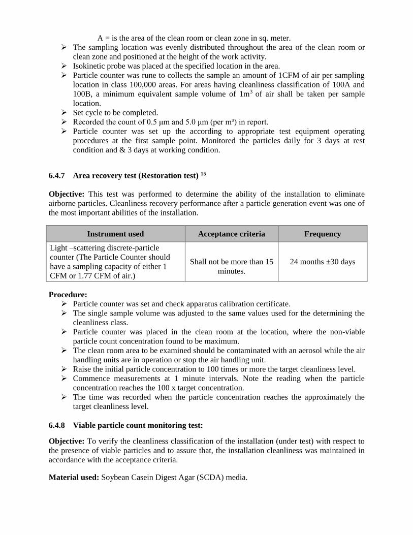
6.4.7 Area recovery test (Restoration test) 15
Objective: This test was performed to determine the ability of the installation to eliminate
airborne particles. Cleanliness recovery performance after a particle generation event was one of
the most important abilities of the installation.
Instrument used Acceptance criteria Frequency
Light –scattering discrete-particle
counter (The Particle Counter should
have a sampling capacity of either 1
CFM or 1.77 CFM of air.)
Shall not be more than 15
minutes.
24 months ±30 days
Procedure: Particle counter was set and check apparatus calibration certificate.
The single sample volume was adjusted to the same values used for the determining the
cleanliness class.
Particle counter was placed in the clean room at the location, where the non-viable
particle count concentration found to be maximum.
The clean room area to be examined should be contaminated with an aerosol while the air
handling units are in operation or stop the air handling unit.
Raise the initial particle concentration to 100 times or more the target cleanliness level.
Commence measurements at 1 minute intervals. Note the reading when the particle
concentration reaches the 100 x target concentration.
The time was recorded when the particle concentration reaches the approximately the
target cleanliness level.
6.4.8 Viable particle count monitoring test:
Objective: To verify the cleanliness classification of the installation (under test) with respect to
the presence of viable particles and to assure that, the installation cleanliness was maintained in
accordance with the acceptance criteria.
Material used: Soybean Casein Digest Agar (SCDA) media.
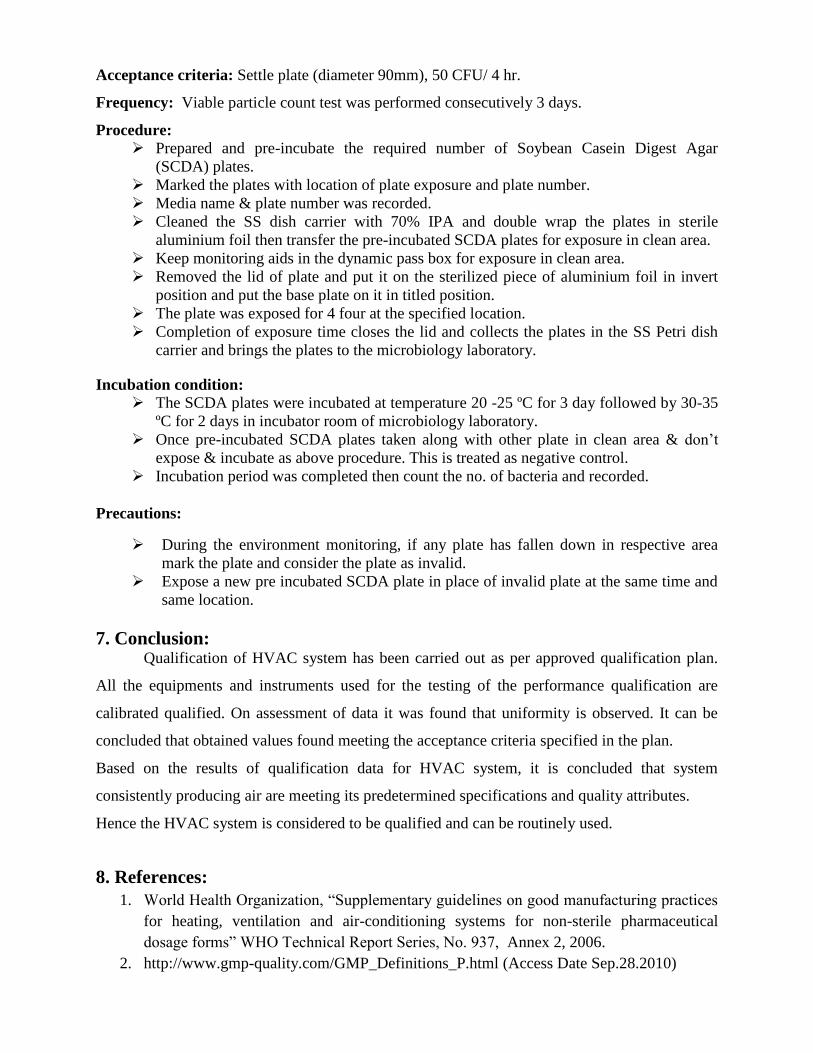
Acceptance criteria: Settle plate (diameter 90mm), 50 CFU/ 4 hr.
Frequency: Viable particle count test was performed consecutively 3 days.
Procedure:
Prepared and pre-incubate the required number of Soybean Casein Digest Agar
(SCDA) plates.
Marked the plates with location of plate exposure and plate number.
Media name & plate number was recorded.
Cleaned the SS dish carrier with 70% IPA and double wrap the plates in sterile
aluminium foil then transfer the pre-incubated SCDA plates for exposure in clean area.
Keep monitoring aids in the dynamic pass box for exposure in clean area.
Removed the lid of plate and put it on the sterilized piece of aluminium foil in invert
position and put the base plate on it in titled position.
The plate was exposed for 4 four at the specified location.
Completion of exposure time closes the lid and collects the plates in the SS Petri dish
carrier and brings the plates to the microbiology laboratory.
Incubation condition:
The SCDA plates were incubated at temperature 20 -25 ºC for 3 day followed by 30-35
ºC for 2 days in incubator room of microbiology laboratory.
Once pre-incubated SCDA plates taken along with other plate in clean area & don’t
expose & incubate as above procedure. This is treated as negative control.
Incubation period was completed then count the no. of bacteria and recorded.
Precautions:
During the environment monitoring, if any plate has fallen down in respective area
mark the plate and consider the plate as invalid.
Expose a new pre incubated SCDA plate in place of invalid plate at the same time and
same location.
7. Conclusion: Qualification of HVAC system has been carried out as per approved qualification plan.
All the equipments and instruments used for the testing of the performance qualification are
calibrated qualified. On assessment of data it was found that uniformity is observed. It can be
concluded that obtained values found meeting the acceptance criteria specified in the plan.
Based on the results of qualification data for HVAC system, it is concluded that system
consistently producing air are meeting its predetermined specifications and quality attributes.
Hence the HVAC system is considered to be qualified and can be routinely used.
8. References:
1. World Health Organization, “Supplementary guidelines on good manufacturing practices
for heating, ventilation and air-conditioning systems for non-sterile pharmaceutical
dosage forms” WHO Technical Report Series, No. 937, Annex 2, 2006.
2. http://www.gmp-quality.com/GMP_Definitions_P.html (Access Date Sep.28.2010)
3. Supplementary guidelines on GMP for HVAC systems for Non-sterile pharmaceutical
dosage forms. In: WHO expert committee on specifications for pharmaceutical
preparations. Fortieth report. Geneva, WHO technical report series, no.937, Annex 2.
4. European Commission. “Good Manufacturing Practice Medicinal Products for Human
and Veterinary Use” Annex 1, Manufacture of sterile medicinal products, 2008.
5. Code of Federal Regulation Title 21, Part 211. Current good manufacturing practice for
finished pharmaceuticals Sec. 211.46 Ventilation, air filtration, air heating and cooling,
2002.
6. Guidance for industry sterile drug products produced by aseptic processing - current good
manufacturing practice, September 2004.
7. EU Guideline to Good Manufacturing Practice medicinal products for human and
veterinary use, Volume 4, Brussels, 2008.
8. Schedule M (Rules 71, 74, 76 and 78)”Good manufacturing practices and requirements of
premises, plant and equipment for pharmaceutical products”, part - 1.
9. Food and Drug Administration, “Guideline on sterile drug products produced by aseptic
processing, FDA, Rockville, MD, 2004.
10. PIC/S, Pharmaceutical Inspection Convention, Pharmaceutical inspection co-operation
scheme, Recommendation on the Validation of Aseptic process, PI 007-5, 1 July 2009.
11. Robert A Nash, “Pharmaceutical process Validation”, Validation of Solid Dosage form,
Ch-12, Published by Marcel Dekker, vol.129, 422-435, 2003.
12. Denys Durand-Viel, “Clean rooms: ISO 14644…What else?" TÜV Rheinland, France
June 2009.
13. Felsmann, C. “Mechanical Equipment & Control Strategies for a Chilled water and a Hot
water system” Final Report of the IEA Task34/Annex43 Subtask D, Technical University
of Dresden, Germany.
14. International Standard Organization, Cleanroom and associated controlled environments,
“Classification of air cleanliness”, Part 1, International standard ISO 14644 -1, 1999.
15. International Standard Organization, Cleanroom and associated controlled environments,
“specification for testing and monitoring to prove continued compliance”, Part 2,
International standard ISO 14644 – 2, 2000.
16. US Food and Drug Administration (FDA) center for drug evaluation and research,
“Guidance for Industry: Sterile Drug Products Produced by Aseptic Processing”, 2004.
17. Gold D.H, “Qualification and Validation of API facilities”, PDA technical report no.22,
PDA J.Pharm.Sci. 50, 5-9, 1996.
18. Buffaloe V, “Process Validation; achieving the operational qualification phase”, Biomed,
Instrum. Tecnol, 38(5), 384-386, 2004.
19. FDA, Guidance for Industry: Sterile Drug Products Produced by Aseptic Processing-
Current Good Manufacturing Practice, 2004.
20. Robert P. Donovan, Penn Well, “Verifying a cleanroom classification”, Clean Rooms,
May, 1999.
21. Jean-Pascal Bourdouxhe, Marc Grodent, and Jean Lebrun, “Reference guide for dynamic
models of HVAC equipment number ISBN 1-883413-60-5”, American society of
Heating, Refrigeration and Air-Conditioning Engineers, Inc., Publication compiled by
ASHRAE. 1998.
22. Lemort, V., Lebrun, J., Felsmann, C. “Testing and validation of simulation tools of
HVAC mechanical equipments include their control strategies”, Part III: Validation of an
air-cooled chiller model, Building Simulation, Glasgow, UK 2009.
23. Robert P. Donovan, Penn Well, “The UCL paradox in the cleanroom standards”, Clean
Rooms, June, 1999.
24. http://pharmacos.eudra.org/F2/eudralex/vol-4/home.htm (Access Date Jan.20.2011).
25. European Commission, “Qualification and Validation”, EU guide to GMP, Annex 15,
Brussels, 5-7, 2001.
26. http://www.askaboutvalidation.com/forum/showthread.php?61-Design-Qualification
(Access Date Nov. 02.2011).
27. http://www.usvalidation.com/kb/iq_procedure.aspx (Access Date Dec.01.2011).
28. htpp://www.validation-online.net/user-requirementsspecification.html (Access Date
Jan.05.2011).
*****