exergy analysis and fuel exergy allocation in a...
TRANSCRIPT

EXERGY ANALYSIS AND FUEL EXERGY ALLOCATION IN A HTGR DIRECT COMBINED CYCLE
Atilio B. Lourenço Federal University of Espírito
Santo, Department of Mechanical Engineering
Vitória, ES, Brazil [email protected]
José Joaquim C. S. Santos Federal University of Espírito
Santo, Department of Mechanical Engineering
Vitória, ES, Brazil [email protected]
João Luiz M. Donatelli Federal University of Espírito
Santo, Department of Mechanical Engineering
Vitória, ES, Brazil [email protected]
ABSTRACT
An exergy and a thermoeconomic analyses are carried out to a high temperature gas-cooled reactor (HTGR) direct combined cycle. The thermoeconomic approach used is the H&S Model, which is based on the disaggregation of physical exergy into its enthalpic and entropic terms. This approach allows the isolation of dissipative components of the productive structure, as condensers. The goal is to calculate the irreversibilities of each subsystem and the exergetic unit cost of each internal flow and product of the system.
Results show that the H&S Model yields consistent results, because exergetic unit costs of internal flows are greater than one and product-fuel ratio of each productive unit are less than one. Besides the allocation of external fuels of the plant, i.e., the nuclear fuel and the fossil fuel, it is shown that the H&S Model can be used in order to quantify both internal and external irreversibilities, as well as the conventional exergy analysis, because the differences between the defined fuels and products of each unit or subsystem of the productive structure are equal to the sums of the exergy destruction and exergy loss values of each unit of the physical structure evaluated by the exergy balance.
Keywords: HTGR Direct Combined Cycle, Exergy Analysis, Thermoeconomics, H&S Model.
INTRODUCTION
The high temperature gas-cooled reactor (HTGR) is a graphite moderated, helium cooled reactor with ceramic-coated fuel particles (TRISO fuel particles). The HTGR is inherently safe and expected to be applied to various industrial fields such as electric generation, hydrogen production, etc. with high efficiencies. It is also recognized as a representative advanced nuclear system for the future [1]. In conventional processes
those products are generated by the combustion of fossil fuels such as coal and natural gas, whose results are significant emissions of greenhouse gases such as carbon dioxide (CO2). For instance, heat or electricity produced in an HTGR could be used to supply process heat or electricity to conventional processes without generating any greenhouse gases [2].
When the working fluid of a HTGR power cycle directly cools the core of the nuclear plant, it is called a direct cycle. If the working fluid of such a cycle and the primary cooling loop of the reactor core are separate, it is called an indirect cycle [2].
The concept of exergy is crucial not only for efficiency studies but also for cost accounting and economic analysis. Because cost is expected to reflect the value (working ability) of the energy carrier, the same working ability is considered to hold the same value. Therefore, exergy is useful as a basis for assigning costs through the so-called thermoeconomic analysis [3].
Thermoeconomics can be considered a new science which, by connecting Thermodynamics and Economics, provides tools to solve problems in complex energy systems that can hardly or not be solved using conventional energy analysis techniques based on First Law of Thermodynamics (mass and energy balance), as for instance a rational price assessment to the products of a plant based on physical criteria [4].
In any energy system, in the same manner that there are productive components, there also exist dissipative components. An energy system has a defined productive structure, but also dissipative ones and both structures are not independent. Although there has been an advance in the development of criteria for the cost allocation of residues, this problem is still open [5].
One of the thermoeconomic methodologies challenges is to define the productive structure of thermal systems that allows allocating rationally the cost of dissipative components to final
1
Proceedings of the 2012 20th International Conference on Nuclear Engineering collocated with the
ASME 2012 Power Conference ICONE20-POWER2012
July 30 - August 3, 2012, Anaheim, California, USA
ICONE20-POWER2012-54523

products. The way in which we define the productive structure is a key point of the thermoeconomic modeling [6]. Different thermoeconomic methodologies can provide different cost values when they define different productive structures. Cost validation is a key issue in thermoeconomics which has not been properly solved yet. However, one considers that cost validation can be designed using the physical behavior of the plant together with Thermodynamics, because irreversibility is the physical magnitude generating the cost [7].
According to [8], depending on the type of analysis, different levels of accuracy of the results are required. Sometimes, under a thermoeconomic analysis point of view, it is necessary to consider a component as a group of subsystem or a mass or an energy flow rate consisting of several components, for example thermal, mechanical or chemical exergy, as proposed by [9], or even to include fictitious flow stream (negentropy) without a physical existence in the flow sheet of the plant, as proposed by [10].
The negentropy flow was applied in thermoeconomics joined up with exergy flow [10]. Negentropy was defined as the negative variation of entropy multiplied by the temperature of the environment. This application represented a great advance in the discipline, since it allowed the quantifying of the condenser product, which was not possible before because the condenser is a dissipative component, whose product cannot be expressed in terms of exergy. The concept of negentropy was also used in order to define the productive structure of a gas turbine cogeneration system [6,11].
However, using negentropy as a fictitious flow (joined up with exergy flow), it is not possible to obtain an efficiency based on the Second Law of Thermodynamics (product-fuel ratio), since the product of dissipative units might be higher than its resource, yielding unit costs lesser than one for some flows [12]. This happens because exergy loss is considered as fuel and negentropy as product. To overcome this problem, the H&S Model was developed [12] to allocate wastes of dissipative component (the condenser) in the thermoeconomic analysis of energy systems. The basis of this method is the breakup of exergy into enthalpy and negentropy. Enthalpy flows replace exergy flows and negentropy flows are used as a component of exergy. Therefore, the productive structure is defined using enthalpy and negentropy flows.
NOMENCLATURE Capital Letters B Exergy F Fuel(s) H Enthalpy productive flow P Product(s) S Syntropy productive flow T Temperature W Power Y Generic productive flow Lowercase Letters h Specific enthalpy k Exergetic unit cost
m Mass flow p Pressure s Specific entropy x Quality Greek Symbols ε Exergetic efficiency η Product-fuel ratio Subscripts 0 Dead state or reference-environment D Destruction H Enthalpy productive unit He Associated to the helium cycle L Loss Q Associated to heat transfer S Syntropy productive unit W Power productive unit cmp Compressor cnd Condenser gtb Gas turbine hxc Heat exchanger i Physical flow in Inlet i:j Difference between flows m Associated to mass flow net Net value out Outlet pmp Pump rct Reactor sht Superheater st Associated to the steam cycle stb Steam turbine PHYSICAL MODEL
A HTGR direct combined cycle is used, in this paper, to illustrate the application of the H&S Model. Such a combined cycle is composed by a topping helium gas cycle and a bottoming steam cycle. The topping cycle has a nuclear reactor which provides exergy to the gas helium. There is a heat exchanger, which works as an interface between those cycles. The bottoming cycle has a superheater, which is fed by a fossil fuel. By using that combined cycle, this paper shows the capacity of the H&S Model to treat an important point in discussion related to the thermoeconomic methodologies: the dissipative components, as condensers. Figure 1 represents the simplified diagram of the combined cycle, which is defined as having eight units: the compressor, the nuclear reactor, the gas turbine, the heat exchanger, the superheater, the steam turbine, the condenser and the pump.
The main assumptions of the modeling are: • Equipments are analyzed as control volumes at
steady state and are adiabatic; • The nuclear fuel and the fossil fuel exergy inlets are
modeled as exergy flows associated to heat flows; • There is no pressure drop for flow through heat
exchangers; • Kinetic and potential energy effects are negligible.
2

Figure 1 Simplified Diagram of the Combined Cycle
EXERGY AND THERMOECONOMIC MODELING In order to carry out a thermoeconomic analysis, the H&S
Model defines the productive purpose of the subsystems (fuels and products), as well as the distribution of the external resources and internal products throughout the system. The productive structure could be represented by means of a functional diagram. In this section, basic concepts of the cost formation are shown. After that, the H&S Model is applied to generate the productive structure of the studied combined cycle. Finally, the exergy balances are done for each equipment of such a cycle.
Productive Structure and Costs Formation
The productive structure represents the cost formation process of the cycle. The external resources consumed by the cycle are the nuclear fuel exergy which feeds the reactor (Brct|Q) and the fossil fuel exergy which feeds the superheater (Bsht|Q). The functional product is the net power provided by the gas turbine and the steam turbine, i.e., the difference between the power provided by both turbines and the power demanded by the compressor and the pump. In this case, a portion of the power generated by the gas turbine (Wgtb) feeds the compressor (Wcmp) and a portion of the power generated by the steam turbine (Wstb) feeds the pump (Wpmp). Rectangles are real units that represent the actual equipment of the cycle. Rhombus and circles are fictitious units called junctions and bifurcations, respectively. Each productive unit has inlet and outlet arrows that represent its fuel, or resources, and products, respectively. Each productive flow is defined based on physical flows.
The mathematical model for the fuels exergy allocation is obtained by formulating the cost balance equation in each productive unit, or subsystem, of the productive structure, as shown in Eq. (1), where k is the exergetic unit cost of productive flows (unknown variable) and Y represents the generic productive flow, which can be internal or external. The exergetic unit cost of the fuels exergy is equal to one.
· 0 (1) Efficiency is defined as the ratio of the desired result for an
event to the input required to accomplish such an event. Therefore, when one defines the fuel and the product during the thermoeconomic modeling, one takes into account that the Second Law efficiency ranges from zero, for a totally irreversible process, to 100 percent, for a totally reversible process [13]. Thus, the exergetic unit cost is the inverse of an efficiency, which is defined as the ratio between the products of a productive unit and the external fuels of the plant.
Since the number of flows is always greater than the number of productive units, some auxiliary equations attribute the same exergetic unit cost to all of productive flows leaving the same bifurcation. The solution of the set of cost balance equations allows the attainment of the exergetic unit cost of each internal flow and final product.
The H&S Model
The physical exergy (Bi) of either a helium gas stream or a steam stream is written as shown in Eq. (2), where h0 and s0 are the specific enthalpy and the specific entropy, both at the dead state for each fluid, respectively. Dead states are at T0, the reference temperature, and at p0, the reference pressure.
· · (2) To generate the productive structure, the H&S Model
considers that the physical exergy must be disaggregated on two components, which are the enthalpic term, here called enthalpy (Hi), and the entropic term, here called syntropy (Si). The productive structure is shown in Fig. 2.
The products and the fuels of each subsystem, in terms of enthalpic and chemical exergy component, are defined based on the quantity of these magnitudes added to and removed from the working fluid, respectively. On the other hand, the entropic component flows are the products of the subsystems that decrease the working fluid entropy, and subsystems that increase the working fluid entropy are entropic components consumers.
Physical flows are calculated as shown in Eqs. (3,4).
rct
hxt
cnd
sht
cmp gtb
stb
32
41
Wcmp Wgtb.net
Wstb
Brct|Q
5
6
7
8
pmp
9
Wpmp
Bsht|Q
3

Figure 2 Productive Structure of the Combined Cycle
· (3) · · (4) Chemical exergy is not considered because there is no
changing in the composition of both fluids throughout the processes of the cycle.
Internal flows of the productive structure are calculated using Eqs. (5,6).
: · (5) : · · (6) The set of cost balance equations is given by Eqs. (7-21). · : . · : . · 0 (7)
· : . · : | (8) · . · : . · : 0 (9)
· : : . · : . · : 0 (10) . · : : · : · : 0 (11) . · : : : · : 0 (12) . · . · 0 (13) · : . · : | (14) · . · : . · : 0 (15)
rct
cmpHHe
H3:2
H2:1
hxc
H4:1
gtb
H3:4
S4:1
S4:3
S2:1
S3:2
WgtbSHe
Wcmp
WHe
H5:9
S5:9
sht
pmp
stb
cnd
H9:8
H6:5
H7:8
H6:7
S9:8
S6:5
S7:8
S7:6
Wpmp
Hst
Sst
Wst
Wstb.netWgtb.net
Bsht|Q
Wnet
WWstb
Brct|Q
4
· : . · : 0 (16) · : . · : . · 0 (17)
. · : : · : · : · : 0 (18)
. · : : : : · : 0 (19) . · . · 0 (20) · . · . . · . 0 (21) One should note that the Figure 2, i.e. the productive
structure of the combined cycle, is the graphical representation of the set of Eqs. (7-21). One should note as well that there are two pairs of fictitious units to distribute costs of the enthalpic and entropic terms, i.e., a pair associated to the gas helium cycle and another one associated to the steam cycle. This is because fluids do not mix each other in the physical structure.
Taking the difference between fuels and products for all real units of the productive structure, the set of Eqs. (22-29) is generated.
: : (22) | : : (23) : : (24) : : : : (25) | : : (26) : : (27) : : (28) : : (29)
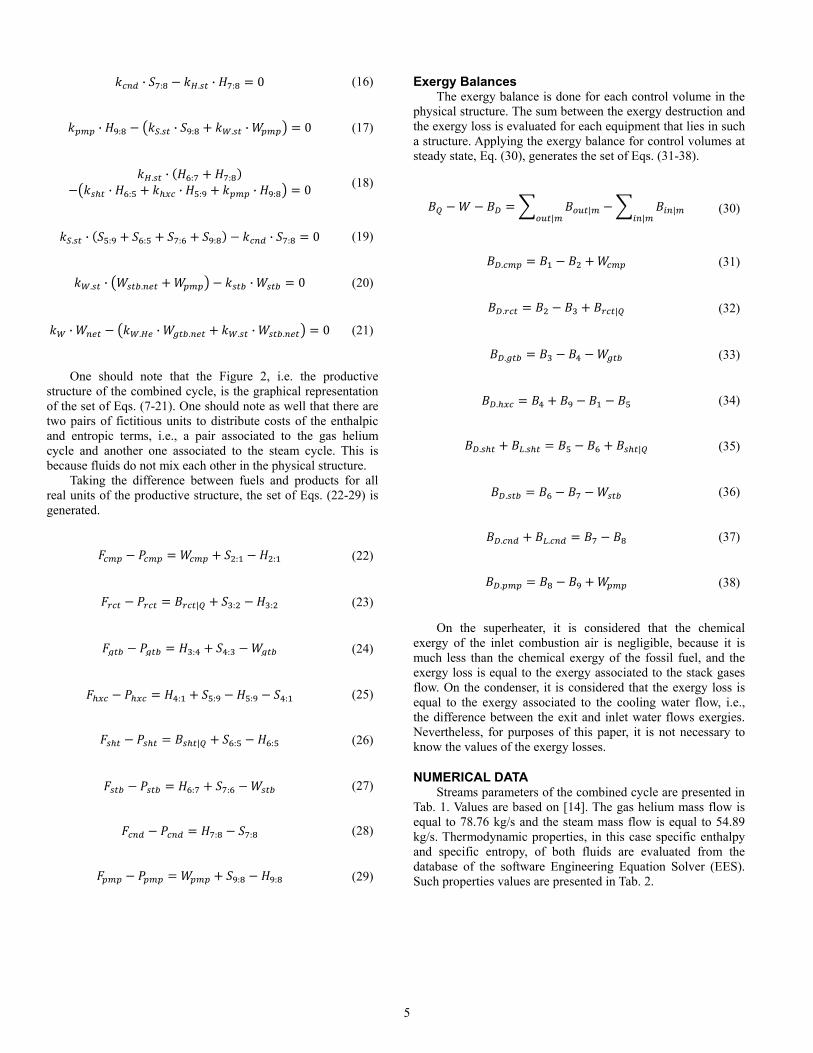
Exergy Balances The exergy balance is done for each control volume in the
physical structure. The sum between the exergy destruction and the exergy loss is evaluated for each equipment that lies in such a structure. Applying the exergy balance for control volumes at steady state, Eq. (30), generates the set of Eqs. (31-38).
|| || (30)
. (31) . | (32) . (33) . (34) . . | (35) . (36) . . (37) . (38) On the superheater, it is considered that the chemical
exergy of the inlet combustion air is negligible, because it is much less than the chemical exergy of the fossil fuel, and the exergy loss is equal to the exergy associated to the stack gases flow. On the condenser, it is considered that the exergy loss is equal to the exergy associated to the cooling water flow, i.e., the difference between the exit and inlet water flows exergies. Nevertheless, for purposes of this paper, it is not necessary to know the values of the exergy losses.
NUMERICAL DATA Streams parameters of the combined cycle are presented in
Tab. 1. Values are based on [14]. The gas helium mass flow is equal to 78.76 kg/s and the steam mass flow is equal to 54.89 kg/s. Thermodynamic properties, in this case specific enthalpy and specific entropy, of both fluids are evaluated from the database of the software Engineering Equation Solver (EES). Such properties values are presented in Tab. 2.
5

Table 1 Streams Parameters of the Combined Cycle
Physical Flow
p [kPa] T [K] i Description 1 Helium 1,000 353.15 2 Helium 4,000 643.95 3 Helium 4,000 1133.15 4 Helium 1,000 699.29 5 Steam (x = 1) 8,300 570.78 6 Steam 8,300 703.15 7 Steam (x = 0.9) 7 312.16 8 Liquid (x = 0) 7 312.16 9 Liquid 8,300 313.06
Table 2 Thermodynamic Properties Evaluated from EES
Physical Flow h [kJ/kg] s [kJ/kg-K]
1 288.81 -3.8753 2 1,807.55 -3.6340 3 4,346.96 -0.7004 4 2,086.06 -0.3281 5 2,753.20 5.7229 6 3,214.76 6.4594 7 2,330.76 7.5023 8 163.36 0.5590 9 174.48 0.5679
The environment temperature T0 is equal to 298 K and the
environment pressure p0 is equal to 1 atm. The exergy supply from the nuclear fuel in the reactor is considered equal to the heat capacity of 200 MWt because of the very high temperature of the fission nuclear reaction [3]. The fossil fuel is methane. The specific chemical exergy of methane is considered equal to 51,848.5 kJ/kg [15]. In order to obtain an agreement with the conventional values of LHV-based efficiencies of conventional boilers, afterburners, etc., it is considered that the methane mass flow is equal to 0.55 kg/s.
The gross power provided by the gas turbine is equal to 178,064.68 kW and the one provided by the steam turbine is equal to 48,523.69 kW. The power demanded by the compressor is equal to 119,613.72 kW and the one demanded by the pump is equal to 610.42 kW.
RESULTS AND DISCUSSION Table 3 shows the exergy balance sheet for the given
numerical data. Percentages are based on total exergy, which is defined by the sum between both fuels exergy inlets. Such a value is also equal to the sum between the net power developed by the combined cycle and the exergy destructions and losses of all equipments.
Table 3 Exergy Balance Sheet
Description Value [kW] Percentage Total Exergy 228,516.68 100%
Exergy in: Nuclear Fuel 200,000.00 87.52% Methane 28,516.68 12.48%
Net Power Developed: Combined Cycle 106,364.23 46.55%
Exergy Destructions and Losses:
Compressor 5,665.10 2.48% Reactor 68,850.85 30.13%
Gas Turbine 8,737.13 3.82% Heat Exchanger 1,070.38 0.47%
Superheater 15,227.90 6.66% Steam Turbine 17,059.42 7.47%
Condenser 5,396.24 2.36% Pump 145.42 0.06%
The exergetic efficiency of the combined cycle, Eq. (39), is
equal to the ratio between the net power developed and the fuels exergy. As seen at the Tab. 3, such a value is equal to 46.55%
| | (39)
Table 4 shows productive flows, its values and its
respective exergetic unit costs for the given numerical data. One should note that there is no exergetic unit cost value
less than one. Taking the inverse of the exergetic unit cost of the net
power, Eq. (40), one obtains the same value of the exergetic efficiency of the combined cycle, i.e., 46.55%.
1
(40)
Table 5 shows the values of the difference between fuels
and products of the real units of the productive structure for the given numerical data.
Values of exergy destructions and losses given at the Tab. 3 are equal to the values obtained at the Tab. 5. Thus, the difference between fuels and products of a real unit of the productive structure is equal to the sum of exergy destruction and loss of the same unit of the physical structure. Actually, one can do some algebra from the set of Eqs. (22-29) and Eqs. (5,6) and obtain the set of Eqs. (31-38).
6

Table 4 Exergetic Unit Costs
Productive Flow Value [kW] Exergetic Unit Cost [kW/kW]
H2:1 119,613.72 1.908 H3:2 200,000.00 1.627 H3:4 178,064.68 1.732 H4:1 141,549.04 1.732 H5:9 141,549.04 1.822 H6:5 25,335.44 2.053 H6:7 48,523.69 1.861 H7:8 118,971.20 1.861 H9:8 610.42 3.011 S2:1 5,665.10 1.822 S3:2 68,850.85 1.822 S4:3 8,737.13 1.822 S4:1 83,253.09 1.822 S5:9 84,323.46 1.950 S6:5 12,046.66 1.950 S7:6 17,059.42 1.950 S7:8 113,574.96 1.950 S9:8 145.42 1.950 Wgtb 178,064.68 1.822 Wcmp 119,613.72 1.822 Wstb 48,523.69 2.547 Wpmp 610.42 2.547
Wgtb.net 58,450.96 1.822 Wstb.net 47,913.27 2.547 Wnet 106,364.23 2.148 Brct|Q 200,000.00 1.000 Bsht|Q 28,516.68 1.000
Table 5 Differences between Fuels and Products of Real Units
Productive Unit Difference Value [kW]
Compressor (cmp) 5,665.10 Reactor (rct) 68,850.85
Gas Turbine (gtb) 8,737.13 Heat Exchanger (hxc) 1,070.38
Superheater (sht) 15,227.90 Steam Turbine (stb) 17,059.42
Condenser (cnd) 5,396.24 Pump (pmp) 147.42
Taking the ratios between products and fuels of the real
productive units, such ratios are defined based on the Second Law of Thermodynamics, the set of Eqs. (41-48) is generated.
: : (41)
:| : (42)
: : (43)
: :: : (44)
:| : (45)
: : (46)
:: (47)
: : (48)
Table 6 shows the values of the product-fuel ratios of the
real productive units for the given numerical data.
Table 6 Product-Fuel Ratios of Real Units
Productive Unit Ratio Value
Compressor (cmp) 95.48% Reactor (rct) 74.39%
Gas Turbine (gtb) 95.32% Heat Exchanger (hxc) 99.53%
Superheater (sht) 62.46% Steam Turbine (stb) 73.99%
Condenser (cnd) 95.46% Pump (pmp) 80.76%
One should note that there is no product-fuel ratio value
greater than one or 100%.
7