exhibit a - connecticut · exhibit a. exhibit b. ... this document is the creation ... the...
TRANSCRIPT

Northeast Site Solutions Denise Sabo 199 Brickyard Rd Farmington, CT 06032 860-209-4690 [email protected]
July 18, 2016
Members of the Siting Council Connecticut Siting Council Ten Franklin Square New Britain, CT 06051
RE: Notice of Exempt Modification 2 Willis Street, Bristol CT 06010 Latitude: 41.6488
Longitude: -72.9474 T-Mobile Site#: CT11270C_L1900
Dear Ms. Bachman:
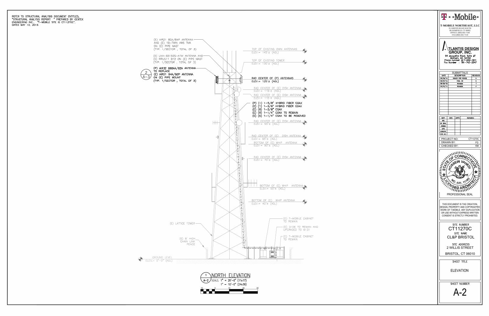
T-Mobile currently maintains nine (9) antennas at the 125-foot level of the existing 145-foot lattice tower at 2 Willis Street, Bristol CT 06010. The tower is owned by Eversource. The property is owned by CT Light and Power Company c/o Eversource. T-Mobile now intends to replace three (3) of its existing antennas with three (3) new 1900/2100 MHz antenna and add (1) hybrid cable. The new antennas would be installed at the 125-foot level of the tower. Planned Modifications:
Remove: (6) 1-1/4” Coax
Remove and Replace: (3)AIR21 B4A /B2P (REMOVE) - (3)AIR32 B66Aa/B2a (REPLACE)
Install New: (1) 1-5/8” Hybrid Cable
Existing to Remain: (3)AIR21 B2A /B4P (3) Commscope LNX-6515 Antenna (3) RRUS11 B12 (3) Twin TMA (6) 1-1/4” Coax (6) 1-5/8” Coax (1) 1-5/8” Hybrid Cable
This facility was approved by the Connecticut Siting Council. Petition No.800 – Approval to replace the existing guyed tower due to age and condition of the tower is was impossible to reinforce. Therefore, approval to replace the existing with tower with new lattice tower of equal height. Please see attached.

Please accept this letter as notification pursuant to Regulations of Connecticut State Agencies§ 16- SOj-73, for construction that constitutes an exempt modification pursuant to R.C.S.A. § 16-50j-72(b)(2). In accordance with R.C.SA. § 16-SOj-73, a copy of this letter is being sent to Mayor Kenneth B. Cockayne, Elected Official for the City of Bristol, as well as the property owner and the tower owner.
The planned modifications to the facility fall squarely within those activities explicitly provided for in R.C.S;A. § 16-50j-72(b)(2).
1. The proposed modifications will not result in an increase in the height of the existing structure.
2. The proposed modifications will not require the extension of the site boundary.
3. The proposed modifications will not increase noise levels at the facility by six decibels or more, or tolevels that exceed state and local criteria.
4. The operation of the replacement antennas will not increase radio frequency emissions at the facility to alevel at or above the Federal Communications Commission safety standard.
5. The proposed modifications will not cause a change or alteration in the physical or environmentalcharacteristics of the site. ·
6. The existing structure and its foundation can support the proposed loading.
For the foregoing reasons, T-Mobile respectfully submits that the proposed modifications to the above referenced telecommunications facility constitute an exempt modification under R.C.S.A. § 16-50j-72(b)(2).
Sincerely,
Denise Sabo Mobile: 860-209-4690 Fax: 413-521-0558 Office: 199 Brickyard Rd, Farmington, CT 06032 Email: [email protected]
Attachments cc: Kenneth B. Cockayne- Mayor - as elected official Eversource - as tower owner CT Light & Power Co c/o Eversource - as property owner

Exhibit A


Exhibit B

Location
Mblu
Acct#
Owner
790 WILLIS ST
06/ / 8A/ /
0034800
CONN LIGHT + POWER CO
Assessment
Appraisal
PID
Building Count
$443,380
$633,400
5681
1
Owner CONN LIGHT + POWER COCo-OwnerAddress 107 SELDEN ST
BERLIN, CT 06037
Sale Price $0Certificate 1Book & Page 277/ 293Sale Date 01/25/1952
Year Built: 1950Living Area: 900Replacement Cost: $39,240Building PercentGood:
65
Replacement CostLess Depreciation: $25,500
Building Attributes
Field Description
STYLE Warehouse
MODEL Ind/Comm
790 WILLIS ST
Current Value
Appraisal
Valuation Year Improvements Land Total
2014 $377,000 $256,400 $633,400
Assessment
Valuation Year Improvements Land Total
2014 $263,900 $179,480 $443,380
Owner of Record
Ownership History
Ownership History
Owner Sale Price Certificate Book & Page Sale Date
CONN LIGHT + POWER CO $0 1 277/ 293 01/25/1952
Building Information
Building 1 : Section 1

Stories: 1
Occupancy 1
Exterior Wall 1 Concr/Cinder
Exterior Wall 2
Roof Structure Gable
Roof Cover Asphalt Shingl
Interior Wall 1 Minim/Masonry
Interior Wall 2
Interior Floor 1 Concr-Finished
Interior Floor 2
Heating Fuel Electric
Heating Type Hot Air-no Duc
AC Type Unit/AC
Bldg Use Public Utility
Bedrooms
Full Baths
Half Baths
1st Floor Use:
Heat/AC Heat/AC Pkgs
Frame Type Masonry
Baths/Plumbing Light
Ceiling/Wall None
Rooms/Prtns Light
Wall Height 8
% Comn Wall
Legend
Building Photo
(http://images.vgsi.com/photos/BristolCTPhotos//\00\02\16/96.jpg)
Building Layout
Building Sub-Areas
Code DescriptionGross Area
LivingArea
BAS First Floor 900 900
SLB Slab 900 0
1800 900
Legend
Land Use
Use Code 436Description Public Utility Zone R-25
Land Line Valuation
Size (Acres) 6.9Frontage 300Depth
Extra Features
Extra Features
No Data for Extra Features
Land
Neighborhood 50Alt Land Appr NoCategory
Assessed Value $179,480Appraised Value $256,400
Legend
(c) 2014 Vision Government Solutions, Inc. All rights reserved.
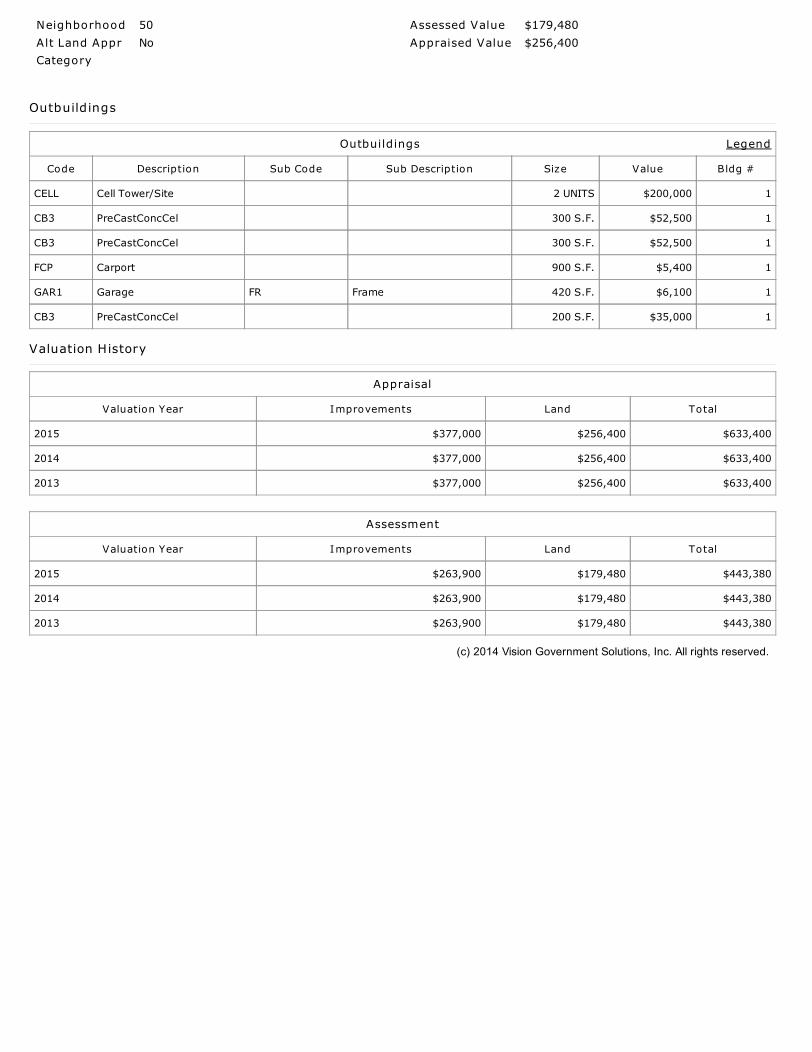
Outbuildings
Outbuildings
Code Description Sub Code Sub Description Size Value Bldg #
CELL Cell Tower/Site 2 UNITS $200,000 1
CB3 PreCastConcCel 300 S.F. $52,500 1
CB3 PreCastConcCel 300 S.F. $52,500 1
FCP Carport 900 S.F. $5,400 1
GAR1 Garage FR Frame 420 S.F. $6,100 1
CB3 PreCastConcCel 200 S.F. $35,000 1
Valuation History
Appraisal
Valuation Year Improvements Land Total
2015 $377,000 $256,400 $633,400
2014 $377,000 $256,400 $633,400
2013 $377,000 $256,400 $633,400
Assessment
Valuation Year Improvements Land Total
2015 $263,900 $179,480 $443,380
2014 $263,900 $179,480 $443,380
2013 $263,900 $179,480 $443,380


Exhibit C

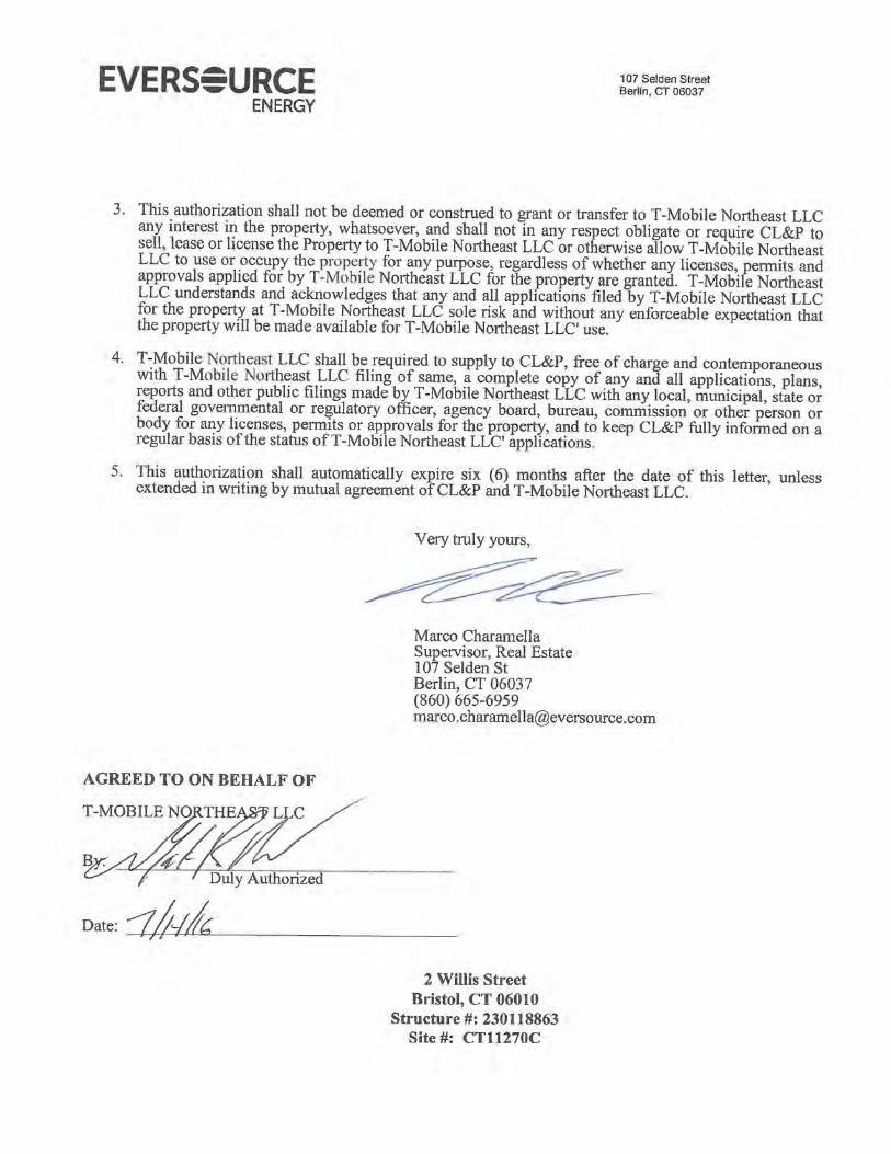

Exhibit D
CHECKED BY:DRAWN BY:PROJECT NO:
KM
THIS DOCUMENT IS THE CREATION,DESIGN, PROPERTY AND COPYRIGHTEDWORK OF T-MOBILE. ANY DUPLICATIONOR USE WITHOUT EXPRESS WRITTENCONSENT IS STRICTLY PROHIBITED.
PROFESSIONAL SEAL
SUBMITTALS
GROUP, INC. TLANTIS DESIGN
FG
CT11270C
CL&P BRISTOL
2 WILLIS STREET
BRISTOL, CT 06010
CT11270C
T-MOBILE NORTHEAST, LLC35 GRIFFIN ROAD SOUTHBLOOMFIELD, CT 06002OFFICE: (860) 692-7100
FAX:(860) 692-7159
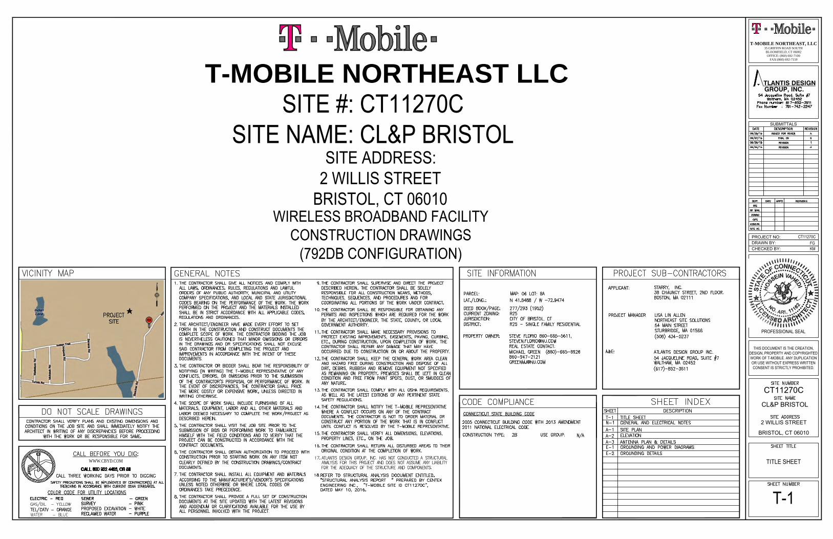
T-MOBILE NORTHEAST LLC
SITE ADDRESS:2 WILLIS STREET
BRISTOL, CT 06010
SITE #: CT11270CSITE NAME: CL&P BRISTOL
WIRELESS BROADBAND FACILITYCONSTRUCTION DRAWINGS
(792DB CONFIGURATION)
TITLE SHEET
T-1
WWW.CBYD.COM
CHECKED BY:DRAWN BY:PROJECT NO:
KM
THIS DOCUMENT IS THE CREATION,DESIGN, PROPERTY AND COPYRIGHTEDWORK OF T-MOBILE. ANY DUPLICATIONOR USE WITHOUT EXPRESS WRITTENCONSENT IS STRICTLY PROHIBITED.
PROFESSIONAL SEAL
SUBMITTALS
GROUP, INC. TLANTIS DESIGN
FG
CT11270C
CL&P BRISTOL
2 WILLIS STREET
BRISTOL, CT 06010
CT11270C
T-MOBILE NORTHEAST, LLC35 GRIFFIN ROAD SOUTHBLOOMFIELD, CT 06002OFFICE: (860) 692-7100
FAX:(860) 692-7159
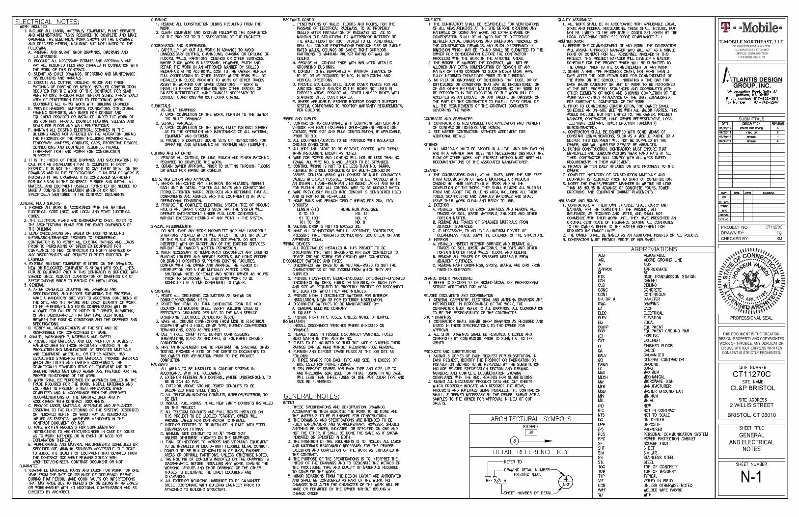
GENERALAND ELECTRICAL
NOTES
N-1

x x x x x
xx
xx
xx
xx
x
xxxxxxx
xx
xx
xx
xx x x
xx
xx
x
x x x
8 0 8 16 24
CHECKED BY:DRAWN BY:PROJECT NO:
KM
THIS DOCUMENT IS THE CREATION,DESIGN, PROPERTY AND COPYRIGHTEDWORK OF T-MOBILE. ANY DUPLICATIONOR USE WITHOUT EXPRESS WRITTENCONSENT IS STRICTLY PROHIBITED.
PROFESSIONAL SEAL
SUBMITTALS
GROUP, INC. TLANTIS DESIGN
FG
CT11270C
CL&P BRISTOL
2 WILLIS STREET
BRISTOL, CT 06010
CT11270C
T-MOBILE NORTHEAST, LLC35 GRIFFIN ROAD SOUTHBLOOMFIELD, CT 06002OFFICE: (860) 692-7100
FAX:(860) 692-7159
SITE PLAN
A-1
CHECKED BY:DRAWN BY:PROJECT NO:
KM
THIS DOCUMENT IS THE CREATION,DESIGN, PROPERTY AND COPYRIGHTEDWORK OF T-MOBILE. ANY DUPLICATIONOR USE WITHOUT EXPRESS WRITTENCONSENT IS STRICTLY PROHIBITED.
PROFESSIONAL SEAL
SUBMITTALS
GROUP, INC. TLANTIS DESIGN
FG
CT11270C
CL&P BRISTOL
2 WILLIS STREET
BRISTOL, CT 06010
CT11270C
T-MOBILE NORTHEAST, LLC35 GRIFFIN ROAD SOUTHBLOOMFIELD, CT 06002OFFICE: (860) 692-7100
FAX:(860) 692-7159
ELEVATION
A-210 0 10 20 30

CHECKED BY:DRAWN BY:PROJECT NO:
KM
THIS DOCUMENT IS THE CREATION,DESIGN, PROPERTY AND COPYRIGHTEDWORK OF T-MOBILE. ANY DUPLICATIONOR USE WITHOUT EXPRESS WRITTENCONSENT IS STRICTLY PROHIBITED.
PROFESSIONAL SEAL
SUBMITTALS
GROUP, INC. TLANTIS DESIGN
FG
CT11270C
CL&P BRISTOL
2 WILLIS STREET
BRISTOL, CT 06010
CT11270C
T-MOBILE NORTHEAST, LLC35 GRIFFIN ROAD SOUTHBLOOMFIELD, CT 06002OFFICE: (860) 692-7100
FAX:(860) 692-7159
ANTENNA PLAN
AND DETAILS
A-3ANTENNA PLANSCALE: N.T.S
ANTENNA MOUNT DETAILSSCALE: N.T.S
ERICSSON AIR32 B66Aa/B2a
8.7"
56.6
"
12.9"
SCALE: N.T.S
ANTENNA DETAILS

CHECKED BY:DRAWN BY:PROJECT NO:
KM
THIS DOCUMENT IS THE CREATION,DESIGN, PROPERTY AND COPYRIGHTEDWORK OF T-MOBILE. ANY DUPLICATIONOR USE WITHOUT EXPRESS WRITTENCONSENT IS STRICTLY PROHIBITED.
PROFESSIONAL SEAL
SUBMITTALS
GROUP, INC. TLANTIS DESIGN
FG
CT11270C
CL&P BRISTOL
2 WILLIS STREET
BRISTOL, CT 06010
CT11270C
T-MOBILE NORTHEAST, LLC35 GRIFFIN ROAD SOUTHBLOOMFIELD, CT 06002OFFICE: (860) 692-7100
FAX:(860) 692-7159
GROUNDINGAND POWERDIAGRAMS
E-1792DB CONFIGURATION
SCALE: N.T.S
COAX/FIBER PLUMBING DIAGRAM

CHECKED BY:DRAWN BY:PROJECT NO:
KM
THIS DOCUMENT IS THE CREATION,DESIGN, PROPERTY AND COPYRIGHTEDWORK OF T-MOBILE. ANY DUPLICATIONOR USE WITHOUT EXPRESS WRITTENCONSENT IS STRICTLY PROHIBITED.
PROFESSIONAL SEAL
SUBMITTALS
GROUP, INC. TLANTIS DESIGN
FG
CT11270C
CL&P BRISTOL
2 WILLIS STREET
BRISTOL, CT 06010
CT11270C
T-MOBILE NORTHEAST, LLC35 GRIFFIN ROAD SOUTHBLOOMFIELD, CT 06002OFFICE: (860) 692-7100
FAX:(860) 692-7159
GROUNDING DETAILS
E-2

Exhibit E

S t r u c t u r a l A n a l y s i s R e p o r t
1 3 0 - f t E x i s t i n g R O H N L a t t i c e T o w e r
P r o p o s e d T - M o b i l eA n t e n n a U p g r a d e
T - M o b i l e S i t e R e f : C T 1 1 2 7 0 C
2 W i l l i s S t r e e tB r i s t o l , C T
C E N T E K P r o j e c t N o . 1 6 0 7 7 . 0 0
D a t e : M a y 1 0 , 2 0 1 6R e v 1 : J u n e 2 3 , 2 0 1 6
Prepared for:T-Mobile Towers
4 Sylvan WayParsippany, NJ 07054

CENTEK Engineering, Inc.Structural Analysis - 130-ft ROHN Lattice TowerT-Mobile Antenna Upgrade – CT11270CBristol, CTRev 1 ~ June 23, 2016
TABLE OF CONTENTS TOC-1
T a b l e o f C o n t e n t sSECTION 1 – REPORT
§ INTRODUCTION
§ ANTENNA AND APPURTENANCE SUMMARY
§ PRIMARY ASSUMPTIONS USED IN THE ANALYSIS
§ ANALYSIS
§ TOWER LOADING
§ TOWER CAPACITY
§ FOUNDATION AND ANCHORS
§ CONCLUSION
SECTION 2 – CONDITIONS & SOFTWARE
§ STANDARD ENGINEERING CONDITIONS
§ GENERAL DESCRIPTION OF STRUCTURAL ANALYSIS PROGRAM
SECTION 3 – CALCULATIONS
§ tnxTower INPUT/OUTPUT SUMMARY
§ tnxTower FEED LINE PLAN
§ tnxTower FEED LINE DISTRIBUTION
§ tnxTower DETAILED OUTPUT
§ ANCHOR BOLT ANALYSIS
§ FOUNDATION ANALYSIS
SECTION 4 – REFERENCE MATERIALS
§ RFDS
§ EQUIPMENT CUT SHEETS
CENTEK Engineering, Inc.Structural Analysis - 130-ft ROHN Lattice TowerT-Mobile Antenna Upgrade – CT11270CBristol, CTRev 1 ~ June 23, 2016
REPORT SECTION 1-1
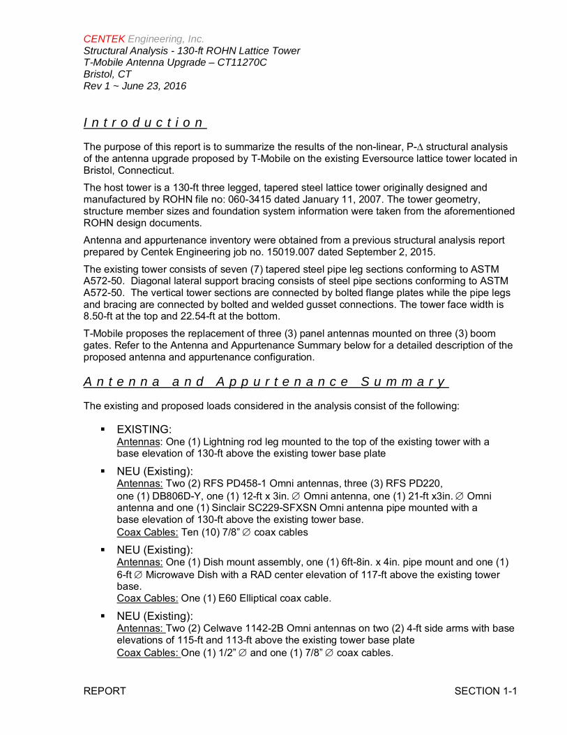
I n t r o d u c t i o n
The purpose of this report is to summarize the results of the non-linear, P-∆ structural analysisof the antenna upgrade proposed by T-Mobile on the existing Eversource lattice tower located inBristol, Connecticut.
The host tower is a 130-ft three legged, tapered steel lattice tower originally designed andmanufactured by ROHN file no: 060-3415 dated January 11, 2007. The tower geometry,structure member sizes and foundation system information were taken from the aforementionedROHN design documents.
Antenna and appurtenance inventory were obtained from a previous structural analysis reportprepared by Centek Engineering job no. 15019.007 dated September 2, 2015.
The existing tower consists of seven (7) tapered steel pipe leg sections conforming to ASTMA572-50. Diagonal lateral support bracing consists of steel pipe sections conforming to ASTMA572-50. The vertical tower sections are connected by bolted flange plates while the pipe legsand bracing are connected by bolted and welded gusset connections. The tower face width is8.50-ft at the top and 22.54-ft at the bottom.
T-Mobile proposes the replacement of three (3) panel antennas mounted on three (3) boomgates. Refer to the Antenna and Appurtenance Summary below for a detailed description of theproposed antenna and appurtenance configuration.
A n t e n n a a n d A p p u r t e n a n c e S u m m a r y
The existing and proposed loads considered in the analysis consist of the following:
§ EXISTING:Antennas: One (1) Lightning rod leg mounted to the top of the existing tower with abase elevation of 130-ft above the existing tower base plate
§ NEU (Existing):Antennas: Two (2) RFS PD458-1 Omni antennas, three (3) RFS PD220,one (1) DB806D-Y, one (1) 12-ft x 3in. Æ Omni antenna, one (1) 21-ft x3in. Æ Omniantenna and one (1) Sinclair SC229-SFXSN Omni antenna pipe mounted with abase elevation of 130-ft above the existing tower base.Coax Cables: Ten (10) 7/8” Æ coax cables
§ NEU (Existing):Antennas: One (1) Dish mount assembly, one (1) 6ft-8in. x 4in. pipe mount and one (1)6-ft Æ Microwave Dish with a RAD center elevation of 117-ft above the existing towerbase.Coax Cables: One (1) E60 Elliptical coax cable.
§ NEU (Existing):Antennas: Two (2) Celwave 1142-2B Omni antennas on two (2) 4-ft side arms with baseelevations of 115-ft and 113-ft above the existing tower base plateCoax Cables: One (1) 1/2” Æ and one (1) 7/8” Æ coax cables.

CENTEK Engineering, Inc.Structural Analysis - 130-ft ROHN Lattice TowerT-Mobile Antenna Upgrade – CT11270CBristol, CTRev 1 ~ June 23, 2016
REPORT SECTION 1-2
§ NEU (Existing):Antennas: One (1) Dish mount assembly, one (1) 6ft-8in. x 4in. pipe mount and one (1)6-ft Æ Microwave Dish with RAD center elevation of 107-ft above the existing tower baseplateCoax Cables: One (1) E65 elliptical Æ coax cable.
§ CSP TROOP H (Existing):Antennas: Two (2) Kathrein AP11-850/105N panel antennas on one (1) 4-ft side armwith RAD center elevations of 105-ft and 104-ft above the existing tower base plateCoax Cables: Two (2) 7/8” Æ coax cables.
§ NEU (Reserved):Antennas: One (1) Dish mount assembly, one (1) 6ft-8in. x 4in. pipe mount and one (1)6-ft Æ Microwave Dish with RAD center elevation of 99-ft above the existing tower baseplateCoax Cables: One (1) E65 elliptical Æ coax cable.
§ NEU (Existing):Antennas: One (1) Andrew/Decibel DB205-A Dipole antenna on (1) 4-ft side arm with aRAD center elevation of 98-ft above the existing tower base.Coax Cables: One (1) 7/8” Æ coax cable.
§ NEU (Existing):Antennas: One (1) Dish mount assembly, one (1) 6ft-8in. x 4in. pipe mount and one (1)8-ft Æ Microwave Dish with a RAD center elevation of 96-ft above the existing towerbase plateCoax Cables: One (1) E60 elliptical Æ coax cable.
§ NEU (Existing):Antennas: One (1) Dish mount assembly, one (1) 6ft-8in. x 4in. pipe mount and one (1)8-ft Æ Microwave Dish with a RAD center elevation of 86-ft above the existing towerbase plateCoax Cables: One (1) E60 elliptical Æ coax cable.
§ NEU (Existing):Antennas: One (1) Celwave 1142-2B Omni antenna mounted on (1) 4-ft side arm with abase elevation of 84-ft above the existing tower base plate.Coax Cables: One (1) 1/2” Æ coax cable.
§ NEU (Existing):Antennas: One (1) 2-ft YAGI antenna pipe mounted with a RAD center elevation of 84-ftabove the existing tower base plate.Coax Cables: One (1) 7/8” Æ coax cable.
CENTEK Engineering, Inc.Structural Analysis - 130-ft ROHN Lattice TowerT-Mobile Antenna Upgrade – CT11270CBristol, CTRev 1 ~ June 23, 2016
REPORT SECTION 1-3
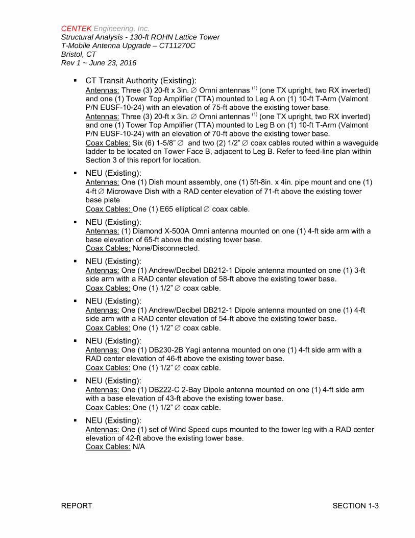
§ CT Transit Authority (Existing):Antennas: Three (3) 20-ft x 3in. Æ Omni antennas (1) (one TX upright, two RX inverted)and one (1) Tower Top Amplifier (TTA) mounted to Leg A on (1) 10-ft T-Arm (ValmontP/N EUSF-10-24) with an elevation of 75-ft above the existing tower base.Antennas: Three (3) 20-ft x 3in. Æ Omni antennas (1) (one TX upright, two RX inverted)and one (1) Tower Top Amplifier (TTA) mounted to Leg B on (1) 10-ft T-Arm (ValmontP/N EUSF-10-24) with an elevation of 70-ft above the existing tower base.Coax Cables: Six (6) 1-5/8” Æ and two (2) 1/2” Æ coax cables routed within a waveguideladder to be located on Tower Face B, adjacent to Leg B. Refer to feed-line plan withinSection 3 of this report for location.
§ NEU (Existing):Antennas: One (1) Dish mount assembly, one (1) 5ft-8in. x 4in. pipe mount and one (1)4-ft Æ Microwave Dish with a RAD center elevation of 71-ft above the existing towerbase plateCoax Cables: One (1) E65 elliptical Æ coax cable.
§ NEU (Existing):Antennas: (1) Diamond X-500A Omni antenna mounted on one (1) 4-ft side arm with abase elevation of 65-ft above the existing tower base.Coax Cables: None/Disconnected.
§ NEU (Existing):Antennas: One (1) Andrew/Decibel DB212-1 Dipole antenna mounted on one (1) 3-ftside arm with a RAD center elevation of 58-ft above the existing tower base.Coax Cables: One (1) 1/2” Æ coax cable.
§ NEU (Existing):Antennas: One (1) Andrew/Decibel DB212-1 Dipole antenna mounted on one (1) 4-ftside arm with a RAD center elevation of 54-ft above the existing tower base.Coax Cables: One (1) 1/2” Æ coax cable.
§ NEU (Existing):Antennas: One (1) DB230-2B Yagi antenna mounted on one (1) 4-ft side arm with aRAD center elevation of 46-ft above the existing tower base.Coax Cables: One (1) 1/2” Æ coax cable.
§ NEU (Existing):Antennas: One (1) DB222-C 2-Bay Dipole antenna mounted on one (1) 4-ft side armwith a base elevation of 43-ft above the existing tower base.Coax Cables: One (1) 1/2” Æ coax cable.
§ NEU (Existing):Antennas: One (1) set of Wind Speed cups mounted to the tower leg with a RAD centerelevation of 42-ft above the existing tower base.Coax Cables: N/A

CENTEK Engineering, Inc.Structural Analysis - 130-ft ROHN Lattice TowerT-Mobile Antenna Upgrade – CT11270CBristol, CTRev 1 ~ June 23, 2016
REPORT SECTION 1-4
§ T-MOBILE (Existing to Remain):Antennas: Three (3) Ericsson AIR21 panel antennas, three (3) Andrew LNX-6515DSpanel antennas, three (3) Ericsson RRUS-11 and three (3) TMA’s mounted on (3)existing 10-ft ROHN boom gates with a RAD center elevation of 125-ft above theexisting tower base.Coax Cables: Six (6) 1-5/8” Æ coax cables, six (6) 1-1/4” Æ coax cables and one (1)1-5/8” Æ fiber cable running on a face of the tower on a cable ladder as specified inSection 3 of this report.
§ T-MOBILE (Existing to Remove):Antennas: Three (3) Ericsson AIR21 panel antennas mounted on (3) existing 10-ftROHN boom gates with a RAD center elevation of 125-ft above the existing towerbase.Coax Cables: Six (6) 1-1/4” Æ coax cables running on a face of the tower on a cableladder as specified in Section 3 of this report.
§ T-MOBILE (Proposed):Antennas: Three (3) Ericsson AIR32 panel antennas mounted on (3) existing10-ft ROHN boom gates with a RAD center elevation of 125-ft above theexisting tower base.Coax Cables: One (1) 1-5/8” Æ fiber cable running on a face of the tower on acable ladder as specified in Section 3 of this report.
P r i m a r y A s s u m p t i o n s U s e d i n t h e A n a l y s i s
§ The tower structure’s theoretical capacity not including any assessment of thecondition of the tower.
§ The tower carries the horizontal and vertical loads due to the weight of antennas, iceload and wind.
§ Tower is properly installed and maintained.
§ Tower is in plumb condition.
§ Tower loading for antennas and mounts as listed in this report.
§ All bolts are appropriately tightened providing the necessary connection continuity.
§ All welds are fabricated with ER-70S-6 electrodes.
§ All members are assumed to be as specified in the original tower design documents.
§ All members are “hot dipped” galvanized in accordance with ASTM A123 and ASTMA153 Standards.
§ All member protective coatings are in good condition.
§ All tower members were properly designed, detailed, fabricated, installed and havebeen properly maintained since erection.
§ Any deviation from the analyzed antenna loading will require a new analysis forverification of structural adequacy.

CENTEK Engineering, Inc.Structural Analysis - 130-ft ROHN Lattice TowerT-Mobile Antenna Upgrade – CT11270CBristol, CTRev 1 ~ June 23, 2016
REPORT SECTION 1-5
A n a l y s i s
The existing tower was analyzed using a comprehensive computer program entitled tnxTower.The program analyzes the tower, considering the worst case loading condition. The tower isconsidered as loaded by concentric forces along the tower legs, and the model assumes thatthe leg members are subjected to bending, axial, and shear forces.
The existing tower was analyzed for 85mph basic wind speed (fastest mile) with no ice and85mph with ½ inch accumulative ice to determine stresses in members as per guidelines ofNortheast Utilities Substation Standard (NU SUB-090), TIA/EIA-222-F-96 entitled “StructuralStandards for Steel Antenna Towers and Antenna Supporting Structures”, the AmericanInstitute of Steel Construction (AISC) and the Manual of Steel Construction; Allowable StressDesign (ASD).
T o w e r L o a d i n g
Tower loading was determined by the basic wind speed as applied to projected surface areaswith modification factors per TIA/EIA-222-F, gravity loads of the tower structure and itscomponents, and the application of ½” radial ice tower structure and its components.
Basic WindSpeed:
Hartford; v = 80 mph (fastest mile)
NU SUB-090; v = 85 mph (fastestmile)
Bristol; v = 95 mph (3 second gust)equivalent to v = 77.5 mph (fastestmile)
NU–SUB-090 wind speed controls
[Section 16 of TIA/EIA-222-F-96]
[Northeast Utilities SubstationStandard 090]
[Appendix K of the 2005 CTBuilding Code Supplement]
Load Cases: Load Case 1; 85 mph wind speed w/no ice plus gravity load – used incalculation of tower stresses androtation. This load case typicallycontrols the design.
[Northeast Utilities SubstationStandard 090]
Load Case 2; 85 mph wind speed w/½” radial ice plus gravity load – usedin calculation of tower stresses. Thisload case typically controls thedesign of lattice towers.
[Northeast Utilities SubstationStandard 090]
Load Case 3; Seismic – not checked [Section 1614.5 of State Bldg.Code 2005] does not control inthe design of this structure type

CENTEK Engineering, Inc.Structural Analysis - 130-ft ROHN Lattice TowerT-Mobile Antenna Upgrade – CT11270CBristol, CTRev 1 ~ June 23, 2016
REPORT SECTION 1-6
T o w e r C a p a c i t y
Tower stresses were calculated utilizing the structural analysis software tnxTower. Allowablestresses were determined based on Table 5 of the TIA/EIA code with a 1/3 increase per Section3.1.1.1 of the same code.
The tower deflection was evaluated with a wind velocity of 85 mph concurrent with 0.5” ice todetermine twist (rotation) and sway (deflection) in accordance with NU SUB-90 requirements.
§ Calculated stresses were found to be within allowable limits. In Load Case 2, pertnxTower “Section Capacity Table”, this tower was found to be at 84.1% of its totalcapacity.
Tower Section Elevation Stress Ratio(percentage of capacity) Result
Leg (T6) 20’-0”-40’-0” 80.6% PASS
Diagonal (T4) 60’-0”-80’-0” 84.1% PASS
Horizontal (T5) 40’-0”-60’-0” 61.7% PASS
§ The tower combined deflection is 0.4631 degrees.
Deflection Criteria Proposed(degrees)
Allowable(degrees) Result
Sway (Tilt) 0.4493 0.5 n/a
Twist 0.1123 0.5 n/a
Combined 0.4631 0.5 PASS
CENTEK Engineering, Inc.Structural Analysis - 130-ft ROHN Lattice TowerT-Mobile Antenna Upgrade – CT11270CBristol, CTRev 1 ~ June 23, 2016
REPORT SECTION 1-7
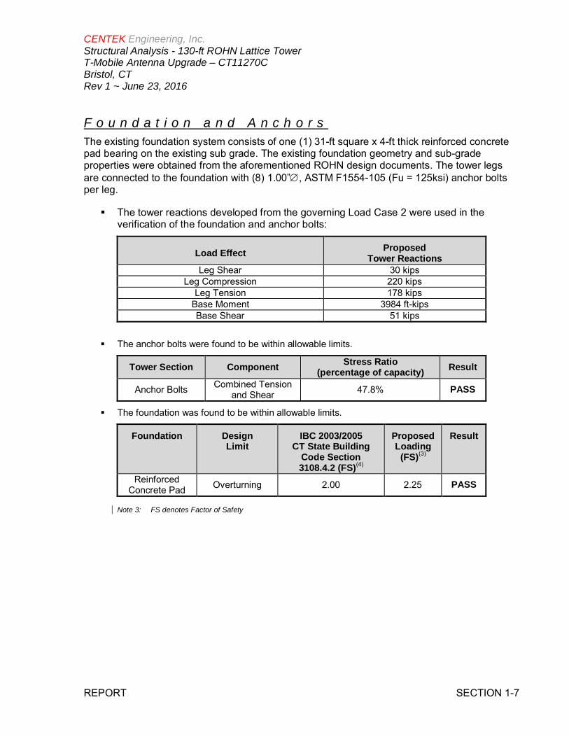
F o u n d a t i o n a n d A n c h o r sThe existing foundation system consists of one (1) 31-ft square x 4-ft thick reinforced concretepad bearing on the existing sub grade. The existing foundation geometry and sub-gradeproperties were obtained from the aforementioned ROHN design documents. The tower legsare connected to the foundation with (8) 1.00Ӯ, ASTM F1554-105 (Fu = 125ksi) anchor boltsper leg.
§ The tower reactions developed from the governing Load Case 2 were used in theverification of the foundation and anchor bolts:
Load Effect ProposedTower Reactions
Leg Shear 30 kipsLeg Compression 220 kips
Leg Tension 178 kipsBase Moment 3984 ft-kipsBase Shear 51 kips
§ The anchor bolts were found to be within allowable limits.
Tower Section Component Stress Ratio(percentage of capacity) Result
Anchor Bolts Combined Tensionand Shear 47.8% PASS
§ The foundation was found to be within allowable limits.
Foundation DesignLimit
IBC 2003/2005CT State Building
Code Section3108.4.2 (FS)(4)
ProposedLoading
(FS)(3)
Result
ReinforcedConcrete Pad Overturning 2.00 2.25 PASS
Note 3: FS denotes Factor of Safety

CENTEK Engineering, Inc.Structural Analysis - 130-ft ROHN Lattice TowerT-Mobile Antenna Upgrade – CT11270CBristol, CTRev 1 ~ June 23, 2016
REPORT SECTION 1-8
C o n c l u s i o nThis analysis shows that the subject tower is adequate to support the proposed modifiedantenna configuration with the below recommendations.
§ All coax cables routed as specified in Section 3 of this report.The analysis is based, in part, on the information provided to this office by T-Mobile. If theexisting conditions are different than the information in this report, Centek Engineering, Inc.must be contacted for resolution of any potential issues.
Please feel free to call with any questions or comments.Respectfully Submitted by:
Timothy J. Lynn, PEStructural Engineer

CENTEK Engineering, Inc.Structural Analysis - 130-ft ROHN Lattice TowerT-Mobile Antenna Upgrade – CT11270CBristol, CTRev 1 ~ June 23, 2016
REPORT SECTION 2-1
S t a n d a r d C o n d i t i o n s f o r F u r n i s h i n g o fP r o f e s s i o n a l E n g i n e e r i n g S e r v i c e s o nE x i s t i n g S t r u c t u r e s
All engineering services are performed on the basis that the information used is current andcorrect. This information may consist of, but is not necessarily limited to:
§ Information supplied by the client regarding the structure itself, its foundations, the soilconditions, the antenna and feed line loading on the structure and its components, orother relevant information.
§ Information from the field and/or drawings in the possession of Centek Engineering, Inc.or generated by field inspections or measurements of the structure.
§ It is the responsibility of the client to ensure that the information provided to CentekEngineering, Inc. and used in the performance of our engineering services is correct andcomplete. In the absence of information to the contrary, we assume that all structureswere constructed in accordance with the drawings and specifications and are in an un-corroded condition and have not deteriorated. It is therefore assumed that its capacityhas not significantly changed from the “as new” condition.
§ All services will be performed to the codes specified by the client, and we do not imply tomeet any other codes or requirements unless explicitly agreed in writing. If wind and iceloads or other relevant parameters are to be different from the minimum valuesrecommended by the codes, the client shall specify the exact requirement. In theabsence of information to the contrary, all work will be performed in accordance with thelatest revision of ANSI/ASCE10 & ANSI/EIA-222
§ All services performed, results obtained, and recommendations made are in accordancewith generally accepted engineering principles and practices. Centek Engineering, Inc.is not responsible for the conclusions, opinions and recommendations made by othersbased on the information we supply.

CENTEK Engineering, Inc.Structural Analysis - 130-ft ROHN Lattice TowerT-Mobile Antenna Upgrade – CT11270CBristol, CTRev 1 ~ June 23, 2016
REPORT SECTION 2-2
G E N E R A L D E S C R I P T I O N O F S T R U C T U R A LA N A L Y S I S P R O G R A M
tnxTower, is an integrated structural analysis and design software package for Designedspecifically for the telecommunications industry, tnxTower, formerly RISA Tower, automatesmuch of the tower analysis and design required by the TIA/EIA 222 Standard.
tnxTower Features:
§ tnxTower can analyze and design 3- and 4-sided guyed towers, 3- and 4-sided self-supporting towers and either round or tapered ground mounted poles with or withoutguys.
§ The program analyzes towers using the TIA-222-G (2005) standard or any of theprevious TIA/EIA standards back to RS-222 (1959). Steel design is checked using theAISC ASD 9th Edition or the AISC LRFD specifications.
§ Linear and non-linear (P-delta) analyses can be used in determining displacements andforces in the structure. Wind pressures and forces are automatically calculated.
§ Extensive graphics plots include material take-off, shear-moment, leg compression,displacement, twist, feed line, guy anchor and stress plots.
§ tnxTower contains unique features such as True Cable behavior, hog rod take-up,foundation stiffness and much more.

Centek Engineering Inc. 63-2 North Branford Rd.
Branford, CT 06405 Phone: (203) 488-0580 FAX: (203) 488-8587
Job: 16077.00 - CT11270C Project: 130-ft ROHN SSMW Tower, Willis Street, Bristol, CT Client: T-Mobile Drawn by: TJL App'd:
Code: TIA/EIA-222-F Date: 06/23/16 Scale: NTS Path:
J:\Jobs\1607700.WI\Backup Documentation\Rev (1)\ERI Files\130-ft ROHN SSMW Lattice Bristol.eri Dwg No. E-1
130.0 ft
120.0 ft
100.0 ft
80.0 ft
60.0 ft
40.0 ft
20.0 ft
0.0 ft
REACTIONS - 85 mph WINDTORQUE 24 kip-ft
37 KSHEAR
2967 kip-ftMOMENT
31 KAXIAL
85 mph WIND - 0.5000 in ICETORQUE 37 kip-ft
51 KSHEAR
3984 kip-ftMOMENT
49 KAXIAL
SHEAR: 26 KUPLIFT: -178 K
SHEAR: 30 KDOWN: 220 K
MAX. CORNER REACTIONS AT BASE:
Sec
tion
T1T2
T3T4
T5T6
T7
Legs
RO
HN
2.5
STD
RO
HN
3S
TDR
OH
N4
STD
RO
HN
5S
TDR
OH
N5
EH
RO
HN
6E
HS
RO
HN
6E
H
Leg
Gra
deA
572-
50
Dia
gona
lsR
OH
N2
STD
RO
HN
2.5
STD
RO
HN
2.5
X-S
TRR
OH
N3
STD
Dia
gona
lGra
deA
572-
50
Top
Girt
sR
OH
N1.
5S
TDR
OH
N2
STD
RO
HN
2.5
STD
Hor
izon
tals
RO
HN
1.5
STD
RO
HN
2S
TDR
OH
N2.
5S
TD
Inne
rBra
cing
L2x2
x1/8
L21/
2x2
1/2x
3/16
L3x3
x3/1
6L3
1/2x
31/
2x1/
4
Face
Wid
th(ft
)8.
58.
5416
710
.625
12.7
083
14.9
583
17.5
417
20.0
417
22.5
417
#P
anel
s@
(ft)
2@
56
@6.
6666
78
@10
Wei
ght(
K)
0.6
1.7
2.0
2.4
2.9
3.5
4.1
17.3
DB806D-Y (NEU) 132PD220 (NEU) 131PD458-1 (NEU) 131PD220 (NEU) 131PD220 (NEU) 13012' x 3" Dia Omni (NEU) 130PD458-1 (NEU) 130Lightning Rod 130SRL-229 (NEU) 13021' x 3" Dia Omni (NEU) 130LNX-6515DS (T-Mobile - Existing) 125LNX-6515DS (T-Mobile - Existing) 125LNX-6515DS (T-Mobile - Existing) 125RRUS-11 (T-Mobile - Existing) 125RRUS-11 (T-Mobile - Existing) 125RRUS-11 (T-Mobile - Existing) 125AIR32 (T-Mobile - Proposed) 125AIR32 (T-Mobile - Proposed) 125AIR32 (T-Mobile - Proposed) 125AIR21 (T-Mobile - Existing) 125AIR21 (T-Mobile - Existing) 125AIR21 (T-Mobile - Existing) 125TMA 10"x8"x3" (T-Mobile - Existing) 125TMA 10"x8"x3" (T-Mobile - Existing) 125TMA 10"x8"x3" (T-Mobile - Existing) 125Rohn 6'x10' Boom Gate (3) (T-Mobile - Existing) 1256'8"x4" Pipe Mount (NEU) 117Dish Mount Assy (NEU) 117PA6-59 1171142-2B (NEU) 115ROHN 4-ft Side Arm (NEU) 115ROHN 4-ft Side Arm (NEU) 1131142-2B (NEU) 1136'8"x4" Pipe Mount (NEU) 107Dish Mount Assy (NEU) 1076 FT DISH 107AP11-850/105N (CSP - Troop H) 105ROHN 4-ft Side Arm (NEU) 104AP11-850/105N (CSP - Troop H) 1046'8"x4" Pipe Mount (NEU) 99Dish Mount Assy (NEU) 996 FT DISH 99ROHN 4-ft Side Arm (NEU) 98DB205-A (NEU) 986'8"x4" Pipe Mount (NEU) 968 FT DISH 96Dish Mount Assy (NEU) 96PAD8-59AW 866'8"x4" Pipe Mount (NEU) 86Dish Mount Assy (NEU) 862' Yagi (NEU) 841142-2B (NEU) 84ROHN 4-ft Side Arm (NEU) 84Valmont T-Arm (1) (CT - Transit) 75TTA 12"x6"x4" (CT - Transit) 7520' x 3" Dia Omni (CT - Transit) 7520' x 3" Dia Omni (CT - Transit) 7520' x 3" Dia Omni (CT - Transit) 756'x2" Pipe Mount (CT - Transit) 756'x2" Pipe Mount (CT - Transit) 754 FT DISH 71Dish Mount Assy (NEU) 715'0"x4.5" Pipe Mount (NEU) 7120' x 3" Dia Omni (CT - Transit) 7020' x 3" Dia Omni (CT - Transit) 7020' x 3" Dia Omni (CT - Transit) 706'x2" Pipe Mount (CT - Transit) 706'x2" Pipe Mount (CT - Transit) 70TTA 12"x6"x4" (CT - Transit) 70Valmont T-Arm (1) (CT - Transit) 70Diamond X-500A (NEU) 65ROHN 4-ft Side Arm (NEU) 65DB212-1 (NEU) 583' Side arm (NEU) 58DB212-1 (NEU) 54ROHN 4-ft Side Arm (NEU) 54DB230-2B (NEU) 46DB222-C (NEU) 43ROHN 4-ft Side Arm (NEU) 43ROHN 4-ft Side Arm (NEU) 43Wind speed cups 42DESIGNED APPURTENANCE LOADINGTYPE TYPEELEVATION ELEVATION
DB806D-Y (NEU) 132PD220 (NEU) 131PD458-1 (NEU) 131PD220 (NEU) 131PD220 (NEU) 13012' x 3" Dia Omni (NEU) 130PD458-1 (NEU) 130Lightning Rod 130SRL-229 (NEU) 13021' x 3" Dia Omni (NEU) 130LNX-6515DS (T-Mobile - Existing) 125LNX-6515DS (T-Mobile - Existing) 125LNX-6515DS (T-Mobile - Existing) 125RRUS-11 (T-Mobile - Existing) 125RRUS-11 (T-Mobile - Existing) 125RRUS-11 (T-Mobile - Existing) 125AIR32 (T-Mobile - Proposed) 125AIR32 (T-Mobile - Proposed) 125AIR32 (T-Mobile - Proposed) 125AIR21 (T-Mobile - Existing) 125AIR21 (T-Mobile - Existing) 125AIR21 (T-Mobile - Existing) 125TMA 10"x8"x3" (T-Mobile - Existing) 125TMA 10"x8"x3" (T-Mobile - Existing) 125TMA 10"x8"x3" (T-Mobile - Existing) 125Rohn 6'x10' Boom Gate (3) (T-Mobile - Existing) 1256'8"x4" Pipe Mount (NEU) 117Dish Mount Assy (NEU) 117PA6-59 1171142-2B (NEU) 115ROHN 4-ft Side Arm (NEU) 115ROHN 4-ft Side Arm (NEU) 1131142-2B (NEU) 1136'8"x4" Pipe Mount (NEU) 107Dish Mount Assy (NEU) 1076 FT DISH 107AP11-850/105N (CSP - Troop H) 105ROHN 4-ft Side Arm (NEU) 104AP11-850/105N (CSP - Troop H) 1046'8"x4" Pipe Mount (NEU) 99Dish Mount Assy (NEU) 99
6 FT DISH 99ROHN 4-ft Side Arm (NEU) 98DB205-A (NEU) 986'8"x4" Pipe Mount (NEU) 968 FT DISH 96Dish Mount Assy (NEU) 96PAD8-59AW 866'8"x4" Pipe Mount (NEU) 86Dish Mount Assy (NEU) 862' Yagi (NEU) 841142-2B (NEU) 84ROHN 4-ft Side Arm (NEU) 84Valmont T-Arm (1) (CT - Transit) 75TTA 12"x6"x4" (CT - Transit) 7520' x 3" Dia Omni (CT - Transit) 7520' x 3" Dia Omni (CT - Transit) 7520' x 3" Dia Omni (CT - Transit) 756'x2" Pipe Mount (CT - Transit) 756'x2" Pipe Mount (CT - Transit) 754 FT DISH 71Dish Mount Assy (NEU) 715'0"x4.5" Pipe Mount (NEU) 7120' x 3" Dia Omni (CT - Transit) 7020' x 3" Dia Omni (CT - Transit) 7020' x 3" Dia Omni (CT - Transit) 706'x2" Pipe Mount (CT - Transit) 706'x2" Pipe Mount (CT - Transit) 70TTA 12"x6"x4" (CT - Transit) 70Valmont T-Arm (1) (CT - Transit) 70Diamond X-500A (NEU) 65ROHN 4-ft Side Arm (NEU) 65DB212-1 (NEU) 583' Side arm (NEU) 58DB212-1 (NEU) 54ROHN 4-ft Side Arm (NEU) 54DB230-2B (NEU) 46DB222-C (NEU) 43ROHN 4-ft Side Arm (NEU) 43ROHN 4-ft Side Arm (NEU) 43Wind speed cups 42
MATERIAL STRENGTHGRADE GRADEFy FyFu Fu
A572-50 50 ksi 65 ksi
TOWER DESIGN NOTES1. Tower designed for a 85 mph basic wind in accordance with the TIA/EIA-222-F Standard.2. Tower is also designed for a 85 mph basic wind with 0.50 in ice.3. Deflections are based upon a 85 mph wind.4. Weld together tower sections have flange connections.5. Connections use galvanized A325 bolts, nuts and locking devices. Installation per TIA/EIA-222 and AISC Specifications.6. Tower members are "hot dipped" galvanized in accordance with ASTM A123 and ASTM A153 Standards.7. Welds are fabricated with ER-70S-6 electrodes.8. TOWER RATING: 84.1%

Centek Engineering Inc. 63-2 North Branford Rd.
Branford, CT 06405 Phone: (203) 488-0580 FAX: (203) 488-8587
Job: 16077.00 - CT11270C Project: 130-ft ROHN SSMW Tower, Willis Street, Bristol, CT Client: T-Mobile Drawn by: TJL App'd:
Code: TIA/EIA-222-F Date: 06/23/16 Scale: NTS Path:
J:\Jobs\1607700.WI\Backup Documentation\Rev (1)\ERI Files\130-ft ROHN SSMW Lattice Bristol.eri Dwg No. E-7
Feed Line Plan
Round Flat App In Face App Out Face
A B
C
(6) 1 5/8 (T-Mobile - Existing)
(10) 7
/8(N
EU)
(2)WE65
(NEU)
7/8(N
EU)
(2)7/8
(CSP
- Troop
H)
7/8(N
EU)
WE65(N
EU)
WE65(N
EU)
1/2(N
EU)
7/8(N
EU)
WE65(N
EU)
1/2(N
EU)
1/2(N
EU)
1/2(N
EU)
1/2(N
EU)
(6) 1 5/8 (CT - Transit)
(3) 1/2 (CT - Transit)Feedline Ladder (Af) (CT - Transit)
HYBRIFLEX 1-5/8" (T-Mobile - Existing)
WE65
(NEU
- Existin
g)
HYBRIFLEX 1-5/8" (T-Mobile - Proposed)
(6) 1 1/4 (T-Mobile - Existing)

Centek Engineering Inc. 63-2 North Branford Rd.
Branford, CT 06405 Phone: (203) 488-0580 FAX: (203) 488-8587
Job: 16077.00 - CT11270C Project: 130-ft ROHN SSMW Tower, Willis Street, Bristol, CT Client: T-Mobile Drawn by: TJL App'd:
Code: TIA/EIA-222-F Date: 06/23/16 Scale: NTS Path:
J:\Jobs\1607700.WI\Backup Documentation\Rev (1)\ERI Files\130-ft ROHN SSMW Lattice Bristol.eri Dwg No. E-7
Feed Line Distribution Chart0' - 130'
Round Flat App In Face App Out Face Truss Leg
Face A
120.00
100.00
80.00
60.00
40.00
20.00
0.00
130.00
Elev
atio
n(ft
)
(6)1
5/8
(T-M
obile
-Exi
stin
g)
HY
BR
IFLE
X1-
5/8"
(T-M
obile
-Exi
stin
g)
HY
BR
IFLE
X1-
5/8"
(T-M
obile
-Pro
pose
d)
(6)1
1/4
(T-M
obile
-Exi
stin
g)
Face B
8.00
123.00
8.008.00
117.00
8.00
113.00
8.00
104.00
8.00
98.00
8.00
107.00
8.00
96.00
8.00
84.00
8.00
84.00
8.00
71.00
8.00
58.00
8.00
54.00
8.00
46.00
8.00
43.00
8.00
75.00
8.00
75.00
8.00
75.00
8.00
123.00
8.00
99.00
8.00
123.00
8.00
123.00
(6)1
5/8
(CT
-Tra
nsit)
(3)1
/2(C
T-T
rans
it)
Feed
line
Ladd
er(A
f)(C
T-T
rans
it)
Face C
120.00
100.00
80.00
60.00
40.00
20.00
0.00
130.00
8.00
123.00
8.008.00
117.00
8.00
113.00
8.00
104.00
8.00
98.00
8.00
107.00
8.00
96.00
8.00
84.00
8.00
84.00
8.00
71.00
8.00
58.00
8.00
54.00
8.00
46.00
8.00
43.00
8.00
75.00
8.00
75.00
8.00
75.00
8.00
123.00
8.00
99.00
8.00
123.00
8.00
123.00
(10)
7/8
(NE
U)
(2)W
E65
(NE
U)
7/8
(NE
U)
(2)7
/8(C
SP
-Tro
opH
)
7/8
(NE
U)
WE
65(N
EU
)
WE
65(N
EU
)
1/2
(NE
U)
7/8
(NE
U)
WE
65(N
EU
)
1/2
(NE
U)
1/2
(NE
U)
1/2
(NE
U)
1/2
(NE
U)
WE
65(N
EU
-Exi
stin
g)

ttnnxxTToowweerr Job16077.00 - CT11270C
Page1 of 39
Centek Engineering Inc.63-2 North Branford Rd.
Project130-ft ROHN SSMW Tower, Willis Street, Bristol, CT
Date15:03:14 06/23/16
Branford, CT 06405Phone: (203) 488-0580FAX: (203) 488-8587
ClientT-Mobile
Designed byTJL
Tower Input Data
The main tower is a 3x free standing tower with an overall height of 130.00 ft above the ground line.The base of the tower is set at an elevation of 0.00 ft above the ground line.The face width of the tower is 8.50 ft at the top and 22.54 ft at the base.This tower is designed using the TIA/EIA-222-F standard.The following design criteria apply:
Basic wind speed of 85 mph.Nominal ice thickness of 0.5000 in.Ice density of 56 pcf.A wind speed of 85 mph is used in combination with ice.Temperature drop of 50 °F.Deflections calculated using a wind speed of 85 mph.Weld together tower sections have flange connections..Connections use galvanized A325 bolts, nuts and locking devices. Installation per TIA/EIA-222 and AISCSpecifications..Tower members are ''hot dipped'' galvanized in accordance with ASTM A123 and ASTM A153 Standards..Welds are fabricated with ER-70S-6 electrodes..A non-linear (P-delta) analysis was used.Pressures are calculated at each section.Stress ratio used in tower member design is 1.333.Local bending stresses due to climbing loads, feed line supports, and appurtenance mounts are not considered.
Options Consider Moments - Legs Distribute Leg Loads As Uniform Use ASCE 10 X-Brace Ly Rules Consider Moments - Horizontals Assume Legs Pinned √ Calculate Redundant Bracing Forces Consider Moments - Diagonals √ Assume Rigid Index Plate Ignore Redundant Members in FEA Use Moment Magnification √ Use Clear Spans For Wind Area SR Leg Bolts Resist Compression√ Use Code Stress Ratios √ Use Clear Spans For KL/r √ All Leg Panels Have Same Allowable Use Code Safety Factors - Guys Retension Guys To Initial Tension Offset Girt At Foundation Escalate Ice Bypass Mast Stability Checks √ Consider Feed Line Torque Always Use Max Kz Use Azimuth Dish Coefficients Include Angle Block Shear Check Use Special Wind Profile √ Project Wind Area of Appurt. Use TIA-222-G Bracing Resist. Exemption√ Include Bolts In Member Capacity Autocalc Torque Arm Areas Use TIA-222-G Tension Splice Exemption Leg Bolts Are At Top Of Section Add IBC .6D+W Combination Poles Secondary Horizontal Braces Leg √ Sort Capacity Reports By Component Include Shear-Torsion Interaction Use Diamond Inner Bracing (4 Sided) Triangulate Diamond Inner Bracing Always Use Sub-Critical Flow SR Members Have Cut Ends Treat Feed Line Bundles As Cylinder Use Top Mounted Sockets SR Members Are Concentric

ttnnxxTToowweerr Job16077.00 - CT11270C
Page2 of 39
Centek Engineering Inc.63-2 North Branford Rd.
Project130-ft ROHN SSMW Tower, Willis Street, Bristol, CT
Date15:03:14 06/23/16
Branford, CT 06405Phone: (203) 488-0580FAX: (203) 488-8587
ClientT-Mobile
Designed byTJL
Leg BLeg C
Leg A
Face
AFace
B
Face C
Triangular To wer
Wind Norma l
Wind 90
Wind 180
ZX
Tower Section GeometryTower
SectionTower
Elevation
ft
AssemblyDatabase
Description SectionWidth
ft
Numberof
Sections
SectionLength
ftT1 130.00-120.00 8.50 1 10.00T2 120.00-100.00 8.54 1 20.00T3 100.00-80.00 10.63 1 20.00T4 80.00-60.00 12.71 1 20.00T5 60.00-40.00 14.96 1 20.00T6 40.00-20.00 17.54 1 20.00T7 20.00-0.00 20.04 1 20.00
Tower Section Geometry (cont’d)Tower
SectionTower
Elevation
ft
DiagonalSpacing
ft
BracingType
HasK Brace
EndPanels
HasHorizontals
Top GirtOffset
in
Bottom GirtOffset
inT1 130.00-120.00 5.00 K Brace Down No Yes 0.0000 0.0000T2 120.00-100.00 6.67 K Brace Down No Yes 0.0000 0.0000T3 100.00-80.00 6.67 K Brace Down No Yes 0.0000 0.0000T4 80.00-60.00 10.00 K Brace Down No Yes 0.0000 0.0000T5 60.00-40.00 10.00 K Brace Down No Yes 0.0000 0.0000T6 40.00-20.00 10.00 K Brace Down No Yes 0.0000 0.0000T7 20.00-0.00 10.00 K Brace Down No Yes 0.0000 0.0000

ttnnxxTToowweerr Job16077.00 - CT11270C
Page3 of 39
Centek Engineering Inc.63-2 North Branford Rd.
Project130-ft ROHN SSMW Tower, Willis Street, Bristol, CT
Date15:03:14 06/23/16
Branford, CT 06405Phone: (203) 488-0580FAX: (203) 488-8587
ClientT-Mobile
Designed byTJL
Tower Section Geometry (cont’d)Tower
Elevationft
LegType
LegSize
LegGrade
DiagonalType
DiagonalSize
DiagonalGrade
T1 130.00-120.00 Pipe ROHN 2.5 STD A572-50(50 ksi)
Pipe ROHN 2 STD A572-50(50 ksi)
T2 120.00-100.00 Pipe ROHN 3 STD A572-50(50 ksi)
Pipe ROHN 2.5 STD A572-50(50 ksi)
T3 100.00-80.00 Pipe ROHN 4 STD A572-50(50 ksi)
Pipe ROHN 2.5 STD A572-50(50 ksi)
T4 80.00-60.00 Pipe ROHN 5 STD A572-50(50 ksi)
Pipe ROHN 2.5 X-STR A572-50(50 ksi)
T5 60.00-40.00 Pipe ROHN 5 EH A572-50(50 ksi)
Pipe ROHN 3 STD A572-50(50 ksi)
T6 40.00-20.00 Pipe ROHN 6 EHS A572-50(50 ksi)
Pipe ROHN 3 STD A572-50(50 ksi)
T7 20.00-0.00 Pipe ROHN 6 EH A572-50(50 ksi)
Pipe ROHN 3 STD A572-50(50 ksi)
Tower Section Geometry (cont’d)Tower
Elevationft
Top GirtType
Top GirtSize
Top GirtGrade
Bottom GirtType
Bottom GirtSize
Bottom GirtGrade
T1 130.00-120.00 Pipe ROHN 1.5 STD A572-50(50 ksi)
Solid Round A36(36 ksi)
T2 120.00-100.00 Pipe ROHN 2 STD A572-50(50 ksi)
Solid Round A36(36 ksi)
T3 100.00-80.00 Pipe ROHN 2 STD A572-50(50 ksi)
Solid Round A36(36 ksi)
T4 80.00-60.00 Pipe ROHN 2 STD A572-50(50 ksi)
Solid Round A36(36 ksi)
T5 60.00-40.00 Pipe ROHN 2 STD A572-50(50 ksi)
Solid Round A36(36 ksi)
T6 40.00-20.00 Pipe ROHN 2.5 STD A572-50(50 ksi)
Solid Round A36(36 ksi)
T7 20.00-0.00 Pipe ROHN 2.5 STD A572-50(50 ksi)
Solid Round A36(36 ksi)
Tower Section Geometry (cont’d)Tower
Elevation
ft
No.of
MidGirts
Mid GirtType
Mid GirtSize
Mid GirtGrade
HorizontalType
HorizontalSize
HorizontalGrade
T1 130.00-120.00 None Flat Bar A36(36 ksi)
Pipe ROHN 1.5 STD A572-50(50 ksi)
T2 120.00-100.00 None Flat Bar A36(36 ksi)
Pipe ROHN 2 STD A572-50(50 ksi)
T3 100.00-80.00 None Flat Bar A36 Pipe ROHN 2 STD A572-50

ttnnxxTToowweerr Job16077.00 - CT11270C
Page4 of 39
Centek Engineering Inc.63-2 North Branford Rd.
Project130-ft ROHN SSMW Tower, Willis Street, Bristol, CT
Date15:03:14 06/23/16
Branford, CT 06405Phone: (203) 488-0580FAX: (203) 488-8587
ClientT-Mobile
Designed byTJL
Tower Elevation
ft
No.of
MidGirts
Mid GirtType
Mid GirtSize
Mid GirtGrade
HorizontalType
HorizontalSize
HorizontalGrade
(36 ksi) (50 ksi)T4 80.00-60.00 None Flat Bar A36
(36 ksi)Pipe ROHN 2 STD A572-50
(50 ksi)T5 60.00-40.00 None Flat Bar A36
(36 ksi)Pipe ROHN 2 STD A572-50
(50 ksi)T6 40.00-20.00 None Flat Bar A36
(36 ksi)Pipe ROHN 2.5 STD A572-50
(50 ksi)T7 20.00-0.00 None Flat Bar A36
(36 ksi)Pipe ROHN 2.5 STD A572-50
(50 ksi)
Tower Section Geometry (cont’d)Tower
Elevation
ft
SecondaryHorizontal Type
Secondary HorizontalSize
SecondaryHorizontal
Grade
Inner BracingType
Inner Bracing Size Inner BracingGrade
T1 130.00-120.00 Solid Round A572-50(50 ksi)
Equal Angle L2x2x1/8 A36(36 ksi)
T2 120.00-100.00 Solid Round A572-50(50 ksi)
Equal Angle L2x2x1/8 A36(36 ksi)
T3 100.00-80.00 Solid Round A572-50(50 ksi)
Equal Angle L2x2x1/8 A36(36 ksi)
T4 80.00-60.00 Solid Round A572-50(50 ksi)
Equal Angle L2x2x1/8 A36(36 ksi)
T5 60.00-40.00 Solid Round A572-50(50 ksi)
Equal Angle L2 1/2x2 1/2x3/16 A36(36 ksi)
T6 40.00-20.00 Solid Round A572-50(50 ksi)
Equal Angle L3x3x3/16 A36(36 ksi)
T7 20.00-0.00 Solid Round A572-50(50 ksi)
Equal Angle L3 1/2x3 1/2x1/4 A36(36 ksi)
Tower Section Geometry (cont’d)Tower
Elevation
ft
GussetArea
(per face)
ft2
GussetThickness
in
Gusset Grade Adjust. FactorAf
Adjust.Factor
Ar
Weight Mult. Double AngleStitch BoltSpacing
Diagonalsin
Double AngleStitch BoltSpacing
Horizontalsin
Double AngleStitch BoltSpacing
Redundantsin
T1130.00-120.00
0.00 0.0000 A36(36 ksi)
1.02 1 1 36.0000 36.0000 36.0000
T2120.00-100.00
0.00 0.0000 A36(36 ksi)
1.02 1 1 36.0000 36.0000 36.0000
T3100.00-80.00
0.00 0.0000 A36(36 ksi)
1.02 1 1 36.0000 36.0000 36.0000
T4 80.00-60.00 0.00 0.0000 A36(36 ksi)
1.02 1 1 36.0000 36.0000 36.0000
T5 60.00-40.00 0.00 0.0000 A36(36 ksi)
1.02 1 1 36.0000 36.0000 36.0000
T6 40.00-20.00 0.00 0.0000 A36(36 ksi)
1.02 1 1 36.0000 36.0000 36.0000
T7 20.00-0.00 0.00 0.0000 A36 1.02 1 1 36.0000 36.0000 36.0000

ttnnxxTToowweerr Job16077.00 - CT11270C
Page5 of 39
Centek Engineering Inc.63-2 North Branford Rd.
Project130-ft ROHN SSMW Tower, Willis Street, Bristol, CT
Date15:03:14 06/23/16
Branford, CT 06405Phone: (203) 488-0580FAX: (203) 488-8587
ClientT-Mobile
Designed byTJL
Tower Elevation
ft
GussetArea
(per face)
ft2
GussetThickness
in
Gusset Grade Adjust. FactorAf
Adjust.Factor
Ar
Weight Mult. Double AngleStitch BoltSpacing
Diagonalsin
Double AngleStitch BoltSpacing
Horizontalsin
Double AngleStitch BoltSpacing
Redundantsin
(36 ksi)
Tower Section Geometry (cont’d)K Factors1
Tower Elevation
ft
CalcK
SingleAngles
CalcK
SolidRounds
Legs XBraceDiags
XY
KBraceDiags
XY
SingleDiags
XY
Girts
XY
Horiz.
XY
Sec.Horiz.
XY
InnerBrace
XY
T1130.00-120.00
Yes Yes 1 11
11
11
11
11
11
11
T2120.00-100.00
Yes Yes 1 11
11
11
11
11
11
11
T3100.00-80.00
Yes Yes 1 11
11
11
11
11
11
11
T480.00-60.00
Yes Yes 1 11
11
11
11
11
11
11
T560.00-40.00
Yes Yes 1 11
11
11
11
11
11
11
T640.00-20.00
Yes Yes 1 11
11
11
11
11
11
11
T7 20.00-0.00 Yes Yes 1 11
11
11
11
11
11
11
1Note: K factors are applied to member segment lengths. K-braces without inner supporting members will have the K factor in the out-of-plane direction applied tothe overall length.
Tower Section Geometry (cont’d)Tower
Elevationft
Leg Diagonal Top Girt Bottom Girt Mid Girt Long Horizontal Short Horizontal
Net WidthDeduct
in
U Net WidthDeduct
in
U Net WidthDeduct
in
U NetWidthDeduct
in
U NetWidthDeduct
in
U NetWidthDeduct
in
U NetWidthDeduct
in
U
T1130.00-120.00
0.0000 1 0.0000 0.75 0.0000 0.75 0.0000 0.75 0.0000 0.75 0.0000 0.75 0.0000 0.75
T2120.00-100.00
0.0000 1 0.0000 0.75 0.0000 0.75 0.0000 0.75 0.0000 0.75 0.0000 0.75 0.0000 0.75
T3100.00-80.00
0.0000 1 0.0000 0.75 0.0000 0.75 0.0000 0.75 0.0000 0.75 0.0000 0.75 0.0000 0.75
T4 80.00-60.00 0.0000 1 0.0000 0.75 0.0000 0.75 0.0000 0.75 0.0000 0.75 0.0000 0.75 0.0000 0.75T5 60.00-40.00 0.0000 1 0.0000 0.75 0.0000 0.75 0.0000 0.75 0.0000 0.75 0.0000 0.75 0.0000 0.75T6 40.00-20.00 0.0000 1 0.0000 0.75 0.0000 0.75 0.0000 0.75 0.0000 0.75 0.0000 0.75 0.0000 0.75T7 20.00-0.00 0.0000 1 0.0000 0.75 0.0000 0.75 0.0000 0.75 0.0000 0.75 0.0000 0.75 0.0000 0.75

ttnnxxTToowweerr Job16077.00 - CT11270C
Page6 of 39
Centek Engineering Inc.63-2 North Branford Rd.
Project130-ft ROHN SSMW Tower, Willis Street, Bristol, CT
Date15:03:14 06/23/16
Branford, CT 06405Phone: (203) 488-0580FAX: (203) 488-8587
ClientT-Mobile
Designed byTJL
Tower Section Geometry (cont’d)Tower
Elevationft
LegConnection
Type
Leg Diagonal Top Girt Bottom Girt Mid Girt Long Horizontal Short Horizontal
Bolt Sizein
No. Bolt Sizein
No. Bolt Sizein
No. Bolt Sizein
No. Bolt Sizein
No. Bolt Sizein
No. Bolt Sizein
No.
T1130.00-120.00
Flange 0.7500A325N
4 0.6250A325N
3 0.6250A325N
2 0.6250A325N
0 0.6250A325N
0 0.6250A325N
2 0.6250A325N
0
T2120.00-100.00
Flange 0.8750A325N
4 0.6250A325N
3 0.6250A325N
2 0.6250A325N
0 0.6250A325N
0 0.6250A325N
2 0.6250A325N
0
T3100.00-80.00
Flange 1.0000A325N
4 0.6250A325N
3 0.6250A325N
2 0.6250A325N
0 0.6250A325N
0 0.6250A325N
2 0.6250A325N
0
T4 80.00-60.00 Flange 1.0000A325N
4 0.6250A325N
3 0.6250A325N
2 0.6250A325N
0 0.6250A325N
0 0.6250A325N
2 0.6250A325N
0
T5 60.00-40.00 Flange 1.0000A325N
6 0.6250A325N
3 0.6250A325N
2 0.6250A325N
0 0.6250A325N
0 0.6250A325N
2 0.6250A325N
0
T6 40.00-20.00 Flange 1.0000A325N
6 0.6250A325N
3 0.6250A325N
2 0.6250A325N
0 0.6250A325N
0 0.6250A325N
2 0.6250A325N
0
T7 20.00-0.00 Flange 1.0000F1554-105
8 0.6250A325N
3 0.6250A325N
2 0.6250A325N
0 0.6250A325N
0 0.6250A325N
2 0.6250A325N
0
Feed Line/Linear Appurtenances - Entered As Round Or FlatDescription Face
orLeg
AllowShield
ComponentType
Placement
ft
FaceOffset
in
LateralOffset
(Frac FW)
# # PerRow
ClearSpacing
in
Width orDiameter
in
Perimeter
in
Weight
plf1 5/8
(T-Mobile -Existing)
A Yes Ar (CfAe) 123.00 - 8.00 2.0000 -0.39 6 3 1.9800 1.9800 1.04
7/8(NEU)
C Yes Ar (CfAe) 130.00 - 8.00 2.0000 -0.37 10 10 0.75001.0000
1.1100 0.54
WE65(NEU)
C Yes Af (CfAe) 117.00 - 8.00 2.0000 -0.3 2 2 1.5836 1.5836 5.1284 0.53
7/8(NEU)
C Yes Ar (CfAe) 113.00 - 8.00 2.0000 -0.4 1 1 0.75001.0000
1.1100 0.54
7/8(CSP - Troop
H)
C Yes Ar (CfAe) 104.00 - 8.00 2.0000 -0.41 2 2 0.75001.0000
1.1100 0.54
7/8(NEU)
C Yes Ar (CfAe) 98.00 - 8.00 2.0000 -0.42 1 1 0.75001.0000
1.1100 0.54
WE65(NEU)
C Yes Af (CfAe) 107.00 - 8.00 2.0000 -0.32 1 1 0.75001.0000
1.5836 5.1284 0.53
WE65(NEU)
C Yes Af (CfAe) 96.00 - 8.00 2.0000 -0.31 1 1 0.75001.0000
1.5836 5.1284 0.53
1/2(NEU)
C Yes Ar (CfAe) 84.00 - 8.00 2.0000 -0.425 1 1 0.75001.0000
0.5800 0.25
7/8(NEU)
C Yes Ar (CfAe) 84.00 - 8.00 2.0000 -0.43 1 1 1.1100 1.1100 0.54
WE65(NEU)
C Yes Af (CfAe) 71.00 - 8.00 2.0000 -0.31 1 1 0.75001.0000
1.5836 5.1284 0.53
1/2(NEU)
C Yes Ar (CfAe) 58.00 - 8.00 2.0000 -0.44 1 1 0.75001.0000
0.5800 0.25
1/2(NEU)
C Yes Ar (CfAe) 54.00 - 8.00 2.0000 -0.47 1 1 0.5800 0.5800 0.25
1/2(NEU)
C Yes Ar (CfAe) 46.00 - 8.00 2.0000 -0.46 1 1 0.5800 0.5800 0.25
1/2 C Yes Ar (CfAe) 43.00 - 8.00 2.0000 -0.45 1 1 0.5800 0.5800 0.25

ttnnxxTToowweerr Job16077.00 - CT11270C
Page7 of 39
Centek Engineering Inc.63-2 North Branford Rd.
Project130-ft ROHN SSMW Tower, Willis Street, Bristol, CT
Date15:03:14 06/23/16
Branford, CT 06405Phone: (203) 488-0580FAX: (203) 488-8587
ClientT-Mobile
Designed byTJL
Description Faceor
Leg
AllowShield
ComponentType
Placement
ft
FaceOffset
in
LateralOffset
(Frac FW)
# # PerRow
ClearSpacing
in
Width orDiameter
in
Perimeter
in
Weight
plf(NEU)1 5/8
(CT - Transit)B Yes Ar (CfAe) 75.00 - 8.00 2.0000 0.4 6 6 1.9800 1.9800 1.04
1/2(CT - Transit)
B Yes Ar (CfAe) 75.00 - 8.00 2.0000 0.345 3 3 0.75001.0000
0.5800 0.25
FeedlineLadder (Af)
(CT - Transit)
B No Af (CfAe) 75.00 - 8.00 2.0000 0.38 1 1 3.0000 3.0000 12.0000 8.40
HYBRIFLEX1-5/8''
(T-Mobile -Existing)
A Yes Ar (CfAe) 123.00 - 8.00 2.0000 -0.35 1 1 1.0000 1.9800 1.90
WE65(NEU -
Existing)
C Yes Af (CfAe) 99.00 - 8.00 2.0000 -0.29 1 1 0.75001.0000
1.5836 5.1284 0.53
HYBRIFLEX1-5/8''
(T-Mobile -Proposed)
A Yes Ar (CfAe) 123.00 - 8.00 5.0000 -0.35 1 1 1.0000 1.9800 1.90
1 1/4(T-Mobile -
Existing)
A Yes Ar (CfAe) 123.00 - 8.00 2.0000 -0.43 6 3 1.5500 1.5500 0.66
Feed Line/Linear Appurtenances Section AreasTowerSection
Tower Elevation
ft
Face AR
ft2
AF
ft2
CAAAIn Face
ft2
CAAAOut Face
ft2
Weight
KT1 130.00-120.00 A
BC
3.6370.0009.250
0.0000.0000.000
0.0000.0000.000
0.0000.0000.000
0.040.000.05
T2 120.00-100.00 ABC
24.2500.000
20.442
0.0000.0005.411
0.0000.0000.000
0.0000.0000.000
0.280.000.14
T3 100.00-80.00 ABC
24.2500.000
26.278
0.0000.000
12.537
0.0000.0000.000
0.0000.0000.000
0.280.000.20
T4 80.00-60.00 ABC
24.25017.02528.717
0.0003.750
14.648
0.0000.0000.000
0.0000.0000.000
0.280.230.23
T5 60.00-40.00 ABC
24.25022.70030.698
0.0005.000
15.836
0.0000.0000.000
0.0000.0000.000
0.280.310.24
T6 40.00-20.00 ABC
24.25022.70032.583
0.0005.000
15.836
0.0000.0000.000
0.0000.0000.000
0.280.310.25
T7 20.00-0.00 ABC
14.55013.62019.550
0.0003.0009.501
0.0000.0000.000
0.0000.0000.000
0.170.180.15
Feed Line/Linear Appurtenances Section Areas - With Ice

ttnnxxTToowweerr Job16077.00 - CT11270C
Page8 of 39
Centek Engineering Inc.63-2 North Branford Rd.
Project130-ft ROHN SSMW Tower, Willis Street, Bristol, CT
Date15:03:14 06/23/16
Branford, CT 06405Phone: (203) 488-0580FAX: (203) 488-8587
ClientT-Mobile
Designed byTJL
TowerSection
Tower Elevation
ft
Faceor
Leg
IceThickness
in
AR
ft2
AF
ft2
CAAA
In Faceft2
CAAA
Out Faceft2
Weight
KT1 130.00-120.00 A
BC
0.500 5.6380.0001.758
0.0000.000
13.950
0.0000.0000.000
0.0000.0000.000
0.100.000.17
T2 120.00-100.00 ABC
0.500 37.5830.0006.506
0.0000.000
36.208
0.0000.0000.000
0.0000.0000.000
0.670.000.45
T3 100.00-80.00 ABC
0.500 37.5830.000
14.945
0.0000.000
48.814
0.0000.0000.000
0.0000.0000.000
0.670.000.65
T4 80.00-60.00 ABC
0.500 37.58324.32520.217
0.0007.908
51.815
0.0000.0000.000
0.0000.0000.000
0.670.440.72
T5 60.00-40.00 ABC
0.500 37.58332.43325.615
0.00010.54453.502
0.0000.0000.000
0.0000.0000.000
0.670.590.77
T6 40.00-20.00 ABC
0.500 37.58332.43330.750
0.00010.54453.502
0.0000.0000.000
0.0000.0000.000
0.670.590.81
T7 20.00-0.00 ABC
0.500 22.55019.46018.450
0.0006.327
32.101
0.0000.0000.000
0.0000.0000.000
0.400.350.49
Feed Line Shielding Section Elevation
ft
Face AR
ft2
AR
Iceft2
AF
ft2
AF
Iceft2
T1 130.00-120.00 ABC
0.3370.0000.857
0.7610.0002.121
0.0000.0000.000
0.0000.0000.000
T2 120.00-100.00 ABC
2.1820.0002.326
4.6390.0005.413
0.0000.0000.000
0.0000.0000.000
T3 100.00-80.00 ABC
2.0230.0003.239
4.3080.0007.612
0.0000.0000.000
0.0000.0000.000
T4 80.00-60.00 ABC
1.4751.0362.638
3.1362.3076.267
0.0000.0000.000
0.0000.0000.000
T5 60.00-40.00 ABC
1.5761.4763.025
3.2423.1807.112
0.0000.0000.000
0.0000.0000.000
T6 40.00-20.00 ABC
1.5971.4953.188
3.2383.1767.545
0.0000.0000.000
0.0000.0000.000
T7 20.00-0.00 ABC
0.9230.8641.843
1.8731.8384.365
0.0000.0000.000
0.0000.0000.000
Feed Line Center of Pressure

ttnnxxTToowweerr Job16077.00 - CT11270C
Page9 of 39
Centek Engineering Inc.63-2 North Branford Rd.
Project130-ft ROHN SSMW Tower, Willis Street, Bristol, CT
Date15:03:14 06/23/16
Branford, CT 06405Phone: (203) 488-0580FAX: (203) 488-8587
ClientT-Mobile
Designed byTJL
Section Elevation
ft
CPX
in
CPZ
in
CPX
Icein
CPZ
Icein
T1 130.00-120.00 3.1271 6.6699 2.8714 6.5277T2 120.00-100.00 -1.8327 9.8315 -2.4119 10.0476T3 100.00-80.00 1.9107 13.0502 1.1264 13.2467T4 80.00-60.00 11.6108 17.8202 11.4129 18.5164T5 60.00-40.00 15.9069 20.5111 16.4617 21.7502T6 40.00-20.00 17.3749 21.8920 18.8843 23.9414T7 20.00-0.00 13.3222 16.7737 14.9633 18.9485
Discrete Tower LoadsDescription Face
orLeg
OffsetType
Offsets:Horz
LateralVert
ftftft
AzimuthAdjustment
°
Placement
ft
CAAA
Front
ft2
CAAA
Side
ft2
Weight
K
Lightning Rod A From Leg 0.000.000.00
2.0000 130.00 No Ice1/2'' Ice
1.002.02
1.002.02
0.040.05
PD220(NEU)
A From Leg 0.000.0010.00
0.0000 131.00 No Ice1/2'' Ice
3.085.30
3.085.30
0.020.05
PD458-1(NEU)
B From Face 0.000.008.00
0.0000 131.00 No Ice1/2'' Ice
2.884.34
2.884.34
0.020.05
PD220(NEU)
B From Face 0.000.0010.00
0.0000 131.00 No Ice1/2'' Ice
3.085.30
3.085.30
0.020.05
PD220(NEU)
B From Leg 0.000.0010.00
0.0000 130.00 No Ice1/2'' Ice
3.085.30
3.085.30
0.020.05
12' x 3'' Dia Omni(NEU)
C From Leg 0.000.006.00
0.0000 130.00 No Ice1/2'' Ice
3.604.83
3.604.83
0.040.06
PD458-1(NEU)
C From Face 0.000.008.00
0.0000 130.00 No Ice1/2'' Ice
2.884.34
2.884.34
0.020.05
DB806D-Y(NEU)
C From Face 0.000.002.50
0.0000 132.00 No Ice1/2'' Ice
2.213.12
2.213.12
0.030.04
SRL-229(NEU)
A From Face 0.000.0010.00
0.0000 130.00 No Ice1/2'' Ice
6.458.63
6.458.63
0.030.07
21' x 3'' Dia Omni(NEU)
A From Face 0.000.0010.00
0.0000 130.00 No Ice1/2'' Ice
6.308.43
6.308.43
0.050.10
LNX-6515DS(T-Mobile - Existing)
A From Leg 4.00-2.000.00
0.0000 125.00 No Ice1/2'' Ice
11.4512.06
7.708.29
0.060.12
LNX-6515DS(T-Mobile - Existing)
B From Leg 4.00-2.000.00
0.0000 125.00 No Ice1/2'' Ice
11.4512.06
7.708.29
0.060.12
LNX-6515DS(T-Mobile - Existing)
C From Leg 4.00-2.000.00
0.0000 125.00 No Ice1/2'' Ice
11.4512.06
7.708.29
0.060.12

ttnnxxTToowweerr Job16077.00 - CT11270C
Page10 of 39
Centek Engineering Inc.63-2 North Branford Rd.
Project130-ft ROHN SSMW Tower, Willis Street, Bristol, CT
Date15:03:14 06/23/16
Branford, CT 06405Phone: (203) 488-0580FAX: (203) 488-8587
ClientT-Mobile
Designed byTJL
Description Faceor
Leg
OffsetType
Offsets:Horz
LateralVert
ftftft
AzimuthAdjustment
°
Placement
ft
CAAA
Front
ft2
CAAA
Side
ft2
Weight
K
RRUS-11(T-Mobile - Existing)
A From Leg 4.00-2.000.00
0.0000 125.00 No Ice1/2'' Ice
2.993.23
1.251.41
0.050.07
RRUS-11(T-Mobile - Existing)
B From Leg 4.00-2.000.00
0.0000 125.00 No Ice1/2'' Ice
2.993.23
1.251.41
0.050.07
RRUS-11(T-Mobile - Existing)
C From Leg 4.00-2.000.00
0.0000 125.00 No Ice1/2'' Ice
2.993.23
1.251.41
0.050.07
AIR32(T-Mobile - Proposed)
A From Leg 4.00-5.000.00
0.0000 125.00 No Ice1/2'' Ice
7.107.55
4.795.21
0.130.18
AIR32(T-Mobile - Proposed)
B From Leg 4.00-5.000.00
0.0000 125.00 No Ice1/2'' Ice
7.107.55
4.795.21
0.130.18
AIR32(T-Mobile - Proposed)
C From Leg 4.00-5.000.00
0.0000 125.00 No Ice1/2'' Ice
7.107.55
4.795.21
0.130.18
AIR21(T-Mobile - Existing)
A From Leg 4.005.000.00
0.0000 125.00 No Ice1/2'' Ice
6.536.98
4.364.77
0.080.12
AIR21(T-Mobile - Existing)
B From Leg 4.005.000.00
0.0000 125.00 No Ice1/2'' Ice
6.536.98
4.364.77
0.080.12
AIR21(T-Mobile - Existing)
C From Leg 4.005.000.00
0.0000 125.00 No Ice1/2'' Ice
6.536.98
4.364.77
0.080.12
TMA 10''x8''x3''(T-Mobile - Existing)
A From Leg 4.000.000.00
0.0000 125.00 No Ice1/2'' Ice
0.780.90
0.290.38
0.020.02
TMA 10''x8''x3''(T-Mobile - Existing)
B From Leg 4.000.000.00
0.0000 125.00 No Ice1/2'' Ice
0.780.90
0.290.38
0.020.02
TMA 10''x8''x3''(T-Mobile - Existing)
C From Leg 4.000.000.00
0.0000 125.00 No Ice1/2'' Ice
0.780.90
0.290.38
0.020.02
Rohn 6'x10' Boom Gate (3)(T-Mobile - Existing)
A From Leg 4.000.000.00
0.0000 125.00 No Ice1/2'' Ice
47.4056.40
47.4056.40
1.622.01
6'8''x4'' Pipe Mount(NEU)
A From Leg 0.500.000.00
0.0000 117.00 No Ice1/2'' Ice
2.603.01
2.603.01
0.070.09
Dish Mount Assy(NEU)
A None 0.0000 117.00 No Ice1/2'' Ice
24.0030.00
24.0030.00
0.420.97
1142-2B(NEU)
C From Leg 4.000.006.00
0.0000 113.00 No Ice1/2'' Ice
1.122.54
1.122.54
0.010.02
ROHN 4-ft Side Arm(NEU)
C From Leg 2.000.000.00
0.0000 113.00 No Ice1/2'' Ice
5.287.88
5.287.88
0.070.08
1142-2B(NEU)
B From Leg 4.000.006.00
0.0000 115.00 No Ice1/2'' Ice
1.122.54
1.122.54
0.010.02
ROHN 4-ft Side Arm(NEU)
B From Leg 2.000.000.00
0.0000 115.00 No Ice1/2'' Ice
5.287.88
5.287.88
0.070.08
AP11-850/105N A From Leg 4.00 0.0000 104.00 No Ice 4.96 2.25 0.01

ttnnxxTToowweerr Job16077.00 - CT11270C
Page11 of 39
Centek Engineering Inc.63-2 North Branford Rd.
Project130-ft ROHN SSMW Tower, Willis Street, Bristol, CT
Date15:03:14 06/23/16
Branford, CT 06405Phone: (203) 488-0580FAX: (203) 488-8587
ClientT-Mobile
Designed byTJL
Description Faceor
Leg
OffsetType
Offsets:Horz
LateralVert
ftftft
AzimuthAdjustment
°
Placement
ft
CAAA
Front
ft2
CAAA
Side
ft2
Weight
K
(CSP - Troop H) 0.000.00
1/2'' Ice 5.36 2.57 0.04
AP11-850/105N(CSP - Troop H)
A From Leg 4.000.000.00
0.0000 105.00 No Ice1/2'' Ice
4.965.36
2.252.57
0.010.04
ROHN 4-ft Side Arm(NEU)
A From Leg 2.000.000.00
0.0000 104.00 No Ice1/2'' Ice
5.287.88
5.287.88
0.070.08
6'8''x4'' Pipe Mount(NEU)
B From Leg 0.500.000.00
0.0000 107.00 No Ice1/2'' Ice
2.603.01
2.603.01
0.070.09
Dish Mount Assy(NEU)
B None 0.0000 107.00 No Ice1/2'' Ice
24.0030.00
24.0030.00
0.420.97
ROHN 4-ft Side Arm(NEU)
C From Leg 2.000.000.00
0.0000 98.00 No Ice1/2'' Ice
5.287.88
5.287.88
0.070.08
DB205-A(NEU)
C From Leg 4.000.009.00
0.0000 98.00 No Ice1/2'' Ice
1.202.16
1.202.16
0.040.05
2' Yagi(NEU)
A From Leg 3.500.000.00
0.0000 84.00 No Ice1/2'' Ice
2.083.79
2.083.79
0.030.05
6'8''x4'' Pipe Mount(NEU)
A From Leg 0.500.000.00
0.0000 96.00 No Ice1/2'' Ice
2.603.01
2.603.01
0.070.09
Dish Mount Assy(NEU)
A None 0.0000 96.00 No Ice1/2'' Ice
24.0030.00
24.0030.00
0.420.97
6'8''x4'' Pipe Mount(NEU)
C From Leg 0.500.000.00
0.0000 86.00 No Ice1/2'' Ice
2.603.01
2.603.01
0.070.09
Dish Mount Assy(NEU)
C None 0.0000 86.00 No Ice1/2'' Ice
24.0030.00
24.0030.00
0.420.97
1142-2B(NEU)
B From Leg 4.000.006.00
0.0000 84.00 No Ice1/2'' Ice
1.122.54
1.122.54
0.010.02
ROHN 4-ft Side Arm(NEU)
B From Leg 2.000.000.00
0.0000 84.00 No Ice1/2'' Ice
5.287.88
5.287.88
0.070.08
5'0''x4.5'' Pipe Mount(NEU)
A From Leg 0.500.000.00
0.0000 71.00 No Ice1/2'' Ice
1.762.08
1.762.08
0.050.07
Dish Mount Assy(NEU)
A None 0.0000 71.00 No Ice1/2'' Ice
24.0030.00
24.0030.00
0.420.97
Diamond X-500A(NEU)
C From Leg 4.000.009.00
0.0000 65.00 No Ice1/2'' Ice
5.407.23
5.407.23
0.050.09
ROHN 4-ft Side Arm(NEU)
C From Leg 2.000.000.00
0.0000 65.00 No Ice1/2'' Ice
5.287.88
5.287.88
0.070.08
DB212-1(NEU)
B From Leg 3.500.000.00
0.0000 58.00 No Ice1/2'' Ice
4.408.42
4.408.42
0.030.07
3' Side arm(NEU)
B From Leg 1.500.000.00
0.0000 58.00 No Ice1/2'' Ice
5.906.60
5.906.60
0.130.15
DB212-1(NEU)
A From Leg 4.000.00
0.0000 54.00 No Ice1/2'' Ice
4.408.42
4.408.42
0.030.07

ttnnxxTToowweerr Job16077.00 - CT11270C
Page12 of 39
Centek Engineering Inc.63-2 North Branford Rd.
Project130-ft ROHN SSMW Tower, Willis Street, Bristol, CT
Date15:03:14 06/23/16
Branford, CT 06405Phone: (203) 488-0580FAX: (203) 488-8587
ClientT-Mobile
Designed byTJL
Description Faceor
Leg
OffsetType
Offsets:Horz
LateralVert
ftftft
AzimuthAdjustment
°
Placement
ft
CAAA
Front
ft2
CAAA
Side
ft2
Weight
K
0.00ROHN 4-ft Side Arm
(NEU)A From Leg 2.00
0.000.00
0.0000 54.00 No Ice1/2'' Ice
5.287.88
5.287.88
0.070.08
DB230-2B(NEU)
B From Leg 4.000.000.00
0.0000 46.00 No Ice1/2'' Ice
2.103.78
2.103.78
0.100.14
ROHN 4-ft Side Arm(NEU)
B From Leg 2.000.000.00
0.0000 43.00 No Ice1/2'' Ice
5.287.88
5.287.88
0.070.08
DB222-C(NEU)
C From Leg 4.000.005.00
0.0000 43.00 No Ice1/2'' Ice
1.602.88
1.602.88
0.020.02
ROHN 4-ft Side Arm(NEU)
C From Leg 2.000.000.00
0.0000 43.00 No Ice1/2'' Ice
5.287.88
5.287.88
0.070.08
Wind speed cups B From Leg 4.000.000.00
0.0000 42.00 No Ice1/2'' Ice
1.802.25
1.802.25
0.040.05
Valmont T-Arm (1)(CT - Transit)
A From Leg 1.500.000.00
0.0000 75.00 No Ice1/2'' Ice
10.5414.45
10.5414.45
0.340.41
TTA 12''x6''x4''(CT - Transit)
A From Leg 3.000.000.00
0.0000 75.00 No Ice1/2'' Ice
0.700.82
0.470.57
0.020.02
TTA 12''x6''x4''(CT - Transit)
B From Leg 3.000.000.00
0.0000 70.00 No Ice1/2'' Ice
0.700.82
0.470.57
0.020.02
Valmont T-Arm (1)(CT - Transit)
B From Leg 1.500.000.00
0.0000 70.00 No Ice1/2'' Ice
10.5414.45
10.5414.45
0.340.41
20' x 3'' Dia Omni(CT - Transit)
A From Leg 3.005.000.00
10.0000 75.00 No Ice1/2'' Ice
6.008.03
6.008.03
0.050.09
20' x 3'' Dia Omni(CT - Transit)
A From Leg 3.005.000.00
-10.0000 75.00 No Ice1/2'' Ice
6.008.03
6.008.03
0.050.09
20' x 3'' Dia Omni(CT - Transit)
A From Leg 3.00-5.000.00
-10.0000 75.00 No Ice1/2'' Ice
6.008.03
6.008.03
0.050.09
20' x 3'' Dia Omni(CT - Transit)
B From Leg 3.005.000.00
10.0000 70.00 No Ice1/2'' Ice
6.008.03
6.008.03
0.050.09
20' x 3'' Dia Omni(CT - Transit)
B From Leg 3.005.000.00
-10.0000 70.00 No Ice1/2'' Ice
6.008.03
6.008.03
0.050.09
20' x 3'' Dia Omni(CT - Transit)
B From Leg 3.00-5.000.00
-10.0000 70.00 No Ice1/2'' Ice
6.008.03
6.008.03
0.050.09
6'x2'' Pipe Mount(CT - Transit)
A From Leg 3.005.000.00
0.0000 75.00 No Ice1/2'' Ice
1.201.80
1.201.80
0.020.03
6'x2'' Pipe Mount(CT - Transit)
A From Leg 3.00-5.000.00
0.0000 75.00 No Ice1/2'' Ice
1.201.80
1.201.80
0.020.03
6'x2'' Pipe Mount(CT - Transit)
B From Leg 3.005.00
0.0000 70.00 No Ice1/2'' Ice
1.201.80
1.201.80
0.020.03

ttnnxxTToowweerr Job16077.00 - CT11270C
Page13 of 39
Centek Engineering Inc.63-2 North Branford Rd.
Project130-ft ROHN SSMW Tower, Willis Street, Bristol, CT
Date15:03:14 06/23/16
Branford, CT 06405Phone: (203) 488-0580FAX: (203) 488-8587
ClientT-Mobile
Designed byTJL
Description Faceor
Leg
OffsetType
Offsets:Horz
LateralVert
ftftft
AzimuthAdjustment
°
Placement
ft
CAAA
Front
ft2
CAAA
Side
ft2
Weight
K
0.006'x2'' Pipe Mount
(CT - Transit)B From Leg 3.00
-5.000.00
0.0000 70.00 No Ice1/2'' Ice
1.201.80
1.201.80
0.020.03
6'8''x4'' Pipe Mount(NEU)
B From Leg 0.500.000.00
0.0000 99.00 No Ice1/2'' Ice
2.603.01
2.603.01
0.070.09
Dish Mount Assy(NEU)
B None 0.0000 99.00 No Ice1/2'' Ice
24.0030.00
24.0030.00
0.420.97
DishesDescription Face
orLeg
DishType
OffsetType
Offsets:Horz
LateralVert
ft
AzimuthAdjustment
°
3 dBBeamWidth
°
Elevation
ft
OutsideDiameter
ft
ApertureArea
ft2
Weight
K4 FT DISH A Paraboloid
w/RadomeFromLeg
0.500.000.00
Worst 71.00 4.00 No Ice1/2'' Ice
12.5713.10
0.140.28
PAD8-59AW C Paraboloidw/Radome
FromLeg
0.500.000.00
Worst 86.00 8.00 No Ice1/2'' Ice
50.2751.29
0.290.55
8 FT DISH A Paraboloidw/Radome
FromLeg
0.500.000.00
Worst 96.00 8.00 No Ice1/2'' Ice
50.2751.32
0.471.01
6 FT DISH B Paraboloidw/Radome
FromLeg
0.500.000.00
Worst 107.00 6.00 No Ice1/2'' Ice
28.2729.05
0.140.29
PA6-59 A Paraboloidw/Radome
FromLeg
0.500.000.00
Worst 117.00 6.00 No Ice1/2'' Ice
28.2729.05
0.090.24
6 FT DISH B Paraboloidw/Radome
FromLeg
0.500.000.00
Worst 99.00 6.00 No Ice1/2'' Ice
28.2729.05
0.140.29
Tower Pressures - No IceGH = 1.143
SectionElevation
ft
z
ft
KZ qz
psf
AG
ft2
Face
AF
ft2
AR
ft2
Aleg
ft2
Leg %
CAAAIn
Faceft2
CAAAOut
Faceft2
T1130.00-120.00
125.00 1.463 27 87.604 ABC
0.0000.0000.000
15.76812.46820.861
4.792 30.3938.4322.97
0.0000.0000.000
0.0000.0000.000

ttnnxxTToowweerr Job16077.00 - CT11270C
Page14 of 39
Centek Engineering Inc.63-2 North Branford Rd.
Project130-ft ROHN SSMW Tower, Willis Street, Bristol, CT
Date15:03:14 06/23/16
Branford, CT 06405Phone: (203) 488-0580FAX: (203) 488-8587
ClientT-Mobile
Designed byTJL
SectionElevation
ft
z
ft
KZ qz
psf
AG
ft2
Face
AF
ft2
AR
ft2
Aleg
ft2
Leg %
CAAA
InFace
ft2
CAAA
OutFace
ft2
T2120.00-100.00
110.00 1.411 26 197.508 ABC
0.0000.0005.411
50.68328.61446.731
11.688 23.0640.8522.42
0.0000.0000.000
0.0000.0000.000
T3100.00-80.00
90.00 1.332 25 240.843 ABC
0.0000.000
12.537
56.27234.04557.085
15.027 26.7044.1421.58
0.0000.0000.000
0.0000.0000.000
T4 80.00-60.00 70.00 1.24 23 285.953 ABC
0.0003.750
14.648
57.87851.09261.182
18.582 32.1133.8824.51
0.0000.0000.000
0.0000.0000.000
T5 60.00-40.00 50.00 1.126 21 334.291 ABC
0.0005.000
15.836
62.12460.67467.123
18.595 29.9328.3122.41
0.0000.0000.000
0.0000.0000.000
T6 40.00-20.00 30.00 1 18 386.897 ABC
0.0005.000
15.836
69.06167.61375.803
22.141 32.0630.4924.16
0.0000.0000.000
0.0000.0000.000
T7 20.00-0.00 10.00 1 18 436.897 ABC
0.0003.0009.501
62.28461.41366.364
22.141 35.5534.3729.18
0.0000.0000.000
0.0000.0000.000
Tower Pressure - With IceGH = 1.143
SectionElevation
ft
z
ft
KZ qz
psf
tZ
in
AG
ft2
Face
AF
ft2
AR
ft2
Aleg
ft2
Leg %
CAAAIn
Faceft2
CAAAOut
Faceft2
T1130.00-120.00
125.00 1.463 27 0.5000 88.438 ABC
0.0000.000
13.950
22.51917.64217.280
6.458 28.6836.6120.68
0.0000.0000.000
0.0000.0000.000
T2120.00-100.00
110.00 1.411 26 0.5000 199.177 ABC
0.0000.000
36.208
71.17538.23139.324
15.027 21.1139.3119.90
0.0000.0000.000
0.0000.0000.000
T3 100.00-80.00 90.00 1.332 25 0.5000 242.512 ABC
0.0000.000
48.814
77.75244.47751.810
18.366 23.6241.2918.25
0.0000.0000.000
0.0000.0000.000
T4 80.00-60.00 70.00 1.24 23 0.5000 287.622 ABC
0.0007.908
51.815
79.01066.58058.512
21.923 27.7529.4319.87
0.0000.0000.000
0.0000.0000.000
T5 60.00-40.00 50.00 1.126 21 0.5000 335.961 ABC
0.00010.54453.502
83.90478.81668.065
21.937 26.1524.5518.05
0.0000.0000.000
0.0000.0000.000
T6 40.00-20.00 30.00 1 18 0.5000 388.566 ABC
0.00010.54453.502
91.55486.46680.414
25.483 27.8326.2719.03
0.0000.0000.000
0.0000.0000.000
T7 20.00-0.00 10.00 1 18 0.5000 438.566 ABC
0.0006.327
32.101
80.85177.79774.259
25.483 31.5230.2923.96
0.0000.0000.000
0.0000.0000.000
Tower Pressure - ServiceGH = 1.143

ttnnxxTToowweerr Job16077.00 - CT11270C
Page15 of 39
Centek Engineering Inc.63-2 North Branford Rd.
Project130-ft ROHN SSMW Tower, Willis Street, Bristol, CT
Date15:03:14 06/23/16
Branford, CT 06405Phone: (203) 488-0580FAX: (203) 488-8587
ClientT-Mobile
Designed byTJL
SectionElevation
ft
z
ft
KZ qz
psf
AG
ft2
Face
AF
ft2
AR
ft2
Aleg
ft2
Leg %
CAAA
InFace
ft2
CAAA
OutFace
ft2
T1130.00-120.00
125.00 1.463 27 87.604 ABC
0.0000.0000.000
15.76812.46820.861
4.792 30.3938.4322.97
0.0000.0000.000
0.0000.0000.000
T2120.00-100.00
110.00 1.411 26 197.508 ABC
0.0000.0005.411
50.68328.61446.731
11.688 23.0640.8522.42
0.0000.0000.000
0.0000.0000.000
T3100.00-80.00
90.00 1.332 25 240.843 ABC
0.0000.000
12.537
56.27234.04557.085
15.027 26.7044.1421.58
0.0000.0000.000
0.0000.0000.000
T4 80.00-60.00 70.00 1.24 23 285.953 ABC
0.0003.750
14.648
57.87851.09261.182
18.582 32.1133.8824.51
0.0000.0000.000
0.0000.0000.000
T5 60.00-40.00 50.00 1.126 21 334.291 ABC
0.0005.000
15.836
62.12460.67467.123
18.595 29.9328.3122.41
0.0000.0000.000
0.0000.0000.000
T6 40.00-20.00 30.00 1 18 386.897 ABC
0.0005.000
15.836
69.06167.61375.803
22.141 32.0630.4924.16
0.0000.0000.000
0.0000.0000.000
T7 20.00-0.00 10.00 1 18 436.897 ABC
0.0003.0009.501
62.28461.41366.364
22.141 35.5534.3729.18
0.0000.0000.000
0.0000.0000.000
Tower Forces - No Ice - Wind Normal To FaceSection
Elevation
ft
AddWeight
K
SelfWeight
K
Face
e CF RR DF DR AE
ft2
F
K
w
plf
Ctrl.Face
T1130.00-120.00
0.10 0.64 ABC
0.180.1420.238
2.6642.8
2.474
0.5870.58
0.599
111
111
9.2487.235
12.494
0.96 95.61 C
T2120.00-100.00
0.42 1.70 ABC
0.2570.1450.264
2.4182.79
2.396
0.6040.5810.606
111
111
30.59116.61733.708
2.41 120.46 C
T3100.00-80.00
0.48 2.04 ABC
0.2340.1410.289
2.4872.8042.325
0.5980.58
0.613
111
111
33.64219.75347.508
3.11 155.59 C
T480.00-60.00
0.74 2.37 ABC
0.2020.1920.265
2.5882.6242.393
0.5910.5890.606
111
111
34.20033.83151.716
3.24 162.19 C
T560.00-40.00
0.83 2.93 ABC
0.1860.1960.248
2.6442.6082.443
0.5880.59
0.601
111
111
36.50540.77956.204
3.27 163.48 C
T640.00-20.00
0.84 3.48 ABC
0.1780.1880.237
2.6692.6382.478
0.5860.5880.599
111
111
40.48744.75461.212
3.21 160.34 C
T7 20.00-0.00 0.50 4.15 ABC
0.1430.1470.174
2.7992.7812.686
0.580.5810.585
111
111
36.14838.68648.350
2.75 137.33 C
Sum Weight: 3.91 17.31 OTM 1178.80kip-ft
18.94

ttnnxxTToowweerr Job16077.00 - CT11270C
Page16 of 39
Centek Engineering Inc.63-2 North Branford Rd.
Project130-ft ROHN SSMW Tower, Willis Street, Bristol, CT
Date15:03:14 06/23/16
Branford, CT 06405Phone: (203) 488-0580FAX: (203) 488-8587
ClientT-Mobile
Designed byTJL
Tower Forces - No Ice - Wind 45 To FaceSection
Elevation
ft
AddWeight
K
SelfWeight
K
Face
e CF RR DF DR AE
ft2
F
K
w
plf
Ctrl.Face
T1130.00-120.00
0.10 0.64 ABC
0.180.1420.238
2.6642.8
2.474
0.5870.58
0.599
0.8250.8250.825
111
9.2487.235
12.494
0.96 95.61 C
T2120.00-100.00
0.42 1.70 ABC
0.2570.1450.264
2.4182.79
2.396
0.6040.5810.606
0.8250.8250.825
111
30.59116.61732.761
2.34 117.08 C
T3100.00-80.00
0.48 2.04 ABC
0.2340.1410.289
2.4872.8042.325
0.5980.58
0.613
0.8250.8250.825
111
33.64219.75345.314
2.97 148.40 C
T480.00-60.00
0.74 2.37 ABC
0.2020.1920.265
2.5882.6242.393
0.5910.5890.606
0.8250.8250.825
111
34.20033.17549.153
3.08 154.15 C
T560.00-40.00
0.83 2.93 ABC
0.1860.1960.248
2.6442.6082.443
0.5880.59
0.601
0.8250.8250.825
111
36.50539.90453.433
3.11 155.42 C
T640.00-20.00
0.84 3.48 ABC
0.1780.1880.237
2.6692.6382.478
0.5860.5880.599
0.8250.8250.825
111
40.48743.87958.441
3.06 153.09 C
T7 20.00-0.00 0.50 4.15 ABC
0.1430.1470.174
2.7992.7812.686
0.580.5810.585
0.8250.8250.825
111
36.14838.16146.687
2.65 132.61 C
Sum Weight: 3.91 17.31 OTM 1133.81kip-ft
18.17
Tower Forces - No Ice - Wind 60 To FaceSection
Elevation
ft
AddWeight
K
SelfWeight
K
Face
e CF RR DF DR AE
ft2
F
K
w
plf
Ctrl.Face
T1130.00-120.00
0.10 0.64 ABC
0.180.1420.238
2.6642.8
2.474
0.5870.58
0.599
0.80.80.8
111
9.2487.235
12.494
0.96 95.61 C
T2120.00-100.00
0.42 1.70 ABC
0.2570.1450.264
2.4182.79
2.396
0.6040.5810.606
0.80.80.8
111
30.59116.61732.626
2.33 116.59 C
T3100.00-80.00
0.48 2.04 ABC
0.2340.1410.289
2.4872.8042.325
0.5980.58
0.613
0.80.80.8
111
33.64219.75345.000
2.95 147.37 C
T480.00-60.00
0.74 2.37 ABC
0.2020.1920.265
2.5882.6242.393
0.5910.5890.606
0.80.80.8
111
34.20033.08148.786
3.06 153.00 C
T560.00-40.00
0.83 2.93 ABC
0.1860.1960.248
2.6442.6082.443
0.5880.59
0.601
0.80.80.8
111
36.50539.77953.037
3.09 154.26 C
T640.00-20.00
0.84 3.48 ABC
0.1780.1880.237
2.6692.6382.478
0.5860.5880.599
0.80.80.8
111
40.48743.75458.045
3.04 152.05 C
T7 20.00-0.00 0.50 4.15 ABC
0.1430.1470.174
2.7992.7812.686
0.580.5810.585
0.80.80.8
111
36.14838.08646.449
2.64 131.93 C
Sum Weight: 3.91 17.31 OTM 1127.38 18.06

ttnnxxTToowweerr Job16077.00 - CT11270C
Page17 of 39
Centek Engineering Inc.63-2 North Branford Rd.
Project130-ft ROHN SSMW Tower, Willis Street, Bristol, CT
Date15:03:14 06/23/16
Branford, CT 06405Phone: (203) 488-0580FAX: (203) 488-8587
ClientT-Mobile
Designed byTJL
SectionElevation
ft
AddWeight
K
SelfWeight
K
Face
e CF RR DF DR AE
ft2
F
K
w
plf
Ctrl.Face
kip-ft
Tower Forces - No Ice - Wind 90 To FaceSection
Elevation
ft
AddWeight
K
SelfWeight
K
Face
e CF RR DF DR AE
ft2
F
K
w
plf
Ctrl.Face
T1130.00-120.00
0.10 0.64 ABC
0.180.1420.238
2.6642.8
2.474
0.5870.58
0.599
0.850.850.85
111
9.2487.235
12.494
0.96 95.61 C
T2120.00-100.00
0.42 1.70 ABC
0.2570.1450.264
2.4182.79
2.396
0.6040.5810.606
0.850.850.85
111
30.59116.61732.897
2.35 117.56 C
T3100.00-80.00
0.48 2.04 ABC
0.2340.1410.289
2.4872.8042.325
0.5980.58
0.613
0.850.850.85
111
33.64219.75345.627
2.99 149.43 C
T480.00-60.00
0.74 2.37 ABC
0.2020.1920.265
2.5882.6242.393
0.5910.5890.606
0.850.850.85
111
34.20033.26949.519
3.11 155.30 C
T560.00-40.00
0.83 2.93 ABC
0.1860.1960.248
2.6442.6082.443
0.5880.59
0.601
0.850.850.85
111
36.50540.02953.829
3.13 156.57 C
T640.00-20.00
0.84 3.48 ABC
0.1780.1880.237
2.6692.6382.478
0.5860.5880.599
0.850.850.85
111
40.48744.00458.837
3.08 154.12 C
T7 20.00-0.00 0.50 4.15 ABC
0.1430.1470.174
2.7992.7812.686
0.580.5810.585
0.850.850.85
111
36.14838.23646.924
2.67 133.28 C
Sum Weight: 3.91 17.31 OTM 1140.23kip-ft
18.28
Tower Forces - With Ice - Wind Normal To FaceSection
Elevation
ft
AddWeight
K
SelfWeight
K
Face
e CF RR DF DR AE
ft2
F
K
w
plf
Ctrl.Face
T1130.00-120.00
0.27 0.97 ABC
0.2550.1990.353
2.4242.5982.164
0.6030.59
0.634
111
111
13.58010.41424.898
1.67 166.71 C
T2120.00-100.00
1.12 2.38 ABC
0.3570.1920.379
2.1552.6232.107
0.6350.5890.643
111
111
45.20522.51061.507
3.86 193.24 C
T3100.00-80.00
1.32 2.84 ABC
0.3210.1830.415
2.2432.6522.035
0.6220.5870.658
111
111
48.39426.11582.895
4.75 237.59 C
T480.00-60.00
1.83 3.12 ABC
0.2750.2590.384
2.3652.4112.097
0.6080.6040.645
111
111
48.07648.13789.557
4.92 246.20 C
T5 2.03 3.81 A 0.25 2.438 0.602 1 1 50.494 4.95 247.26 C
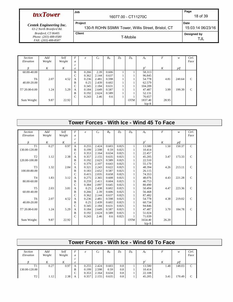
ttnnxxTToowweerr Job16077.00 - CT11270C
Page18 of 39
Centek Engineering Inc.63-2 North Branford Rd.
Project130-ft ROHN SSMW Tower, Willis Street, Bristol, CT
Date15:03:14 06/23/16
Branford, CT 06405Phone: (203) 488-0580FAX: (203) 488-8587
ClientT-Mobile
Designed byTJL
SectionElevation
ft
AddWeight
K
SelfWeight
K
Face
e CF RR DF DR AE
ft2
F
K
w
plf
Ctrl.Face
60.00-40.00 BC
0.2660.362
2.392.144
0.6060.637
11
11
58.31396.845
T640.00-20.00
2.07 4.52 ABC
0.2360.25
0.345
2.4812.4392.184
0.5980.6020.631
111
111
54.77862.579
104.209
4.81 240.64 C
T7 20.00-0.00 1.24 5.29 ABC
0.1840.1920.243
2.6492.624
2.46
0.5870.589
0.6
111
111
47.48752.13176.657
3.99 199.39 C
Sum Weight: 9.87 22.92 OTM 1837.40kip-ft
28.95
Tower Forces - With Ice - Wind 45 To FaceSection
Elevation
ft
AddWeight
K
SelfWeight
K
Face
e CF RR DF DR AE
ft2
F
K
w
plf
Ctrl.Face
T1130.00-120.00
0.27 0.97 ABC
0.2550.1990.353
2.4242.5982.164
0.6030.59
0.634
0.8250.8250.825
111
13.58010.41422.457
1.50 150.37 C
T2120.00-100.00
1.12 2.38 ABC
0.3570.1920.379
2.1552.6232.107
0.6350.5890.643
0.8250.8250.825
111
45.20522.51055.170
3.47 173.33 C
T3100.00-80.00
1.32 2.84 ABC
0.3210.1830.415
2.2432.6522.035
0.6220.5870.658
0.8250.8250.825
111
48.39426.11574.353
4.26 213.11 C
T480.00-60.00
1.83 3.12 ABC
0.2750.2590.384
2.3652.4112.097
0.6080.6040.645
0.8250.8250.825
111
48.07646.75380.490
4.43 221.28 C
T560.00-40.00
2.03 3.81 ABC
0.250.2660.362
2.4382.39
2.144
0.6020.6060.637
0.8250.8250.825
111
50.49456.46887.482
4.47 223.36 C
T640.00-20.00
2.07 4.52 ABC
0.2360.25
0.345
2.4812.4392.184
0.5980.6020.631
0.8250.8250.825
111
54.77860.73494.846
4.38 219.02 C
T7 20.00-0.00 1.24 5.29 ABC
0.1840.1920.243
2.6492.624
2.46
0.5870.589
0.6
0.8250.8250.825
111
47.48751.02471.039
3.70 184.78 C
Sum Weight: 9.87 22.92 OTM 1654.40kip-ft
26.20
Tower Forces - With Ice - Wind 60 To FaceSection
Elevation
ft
AddWeight
K
SelfWeight
K
Face
e CF RR DF DR AE
ft2
F
K
w
plf
Ctrl.Face
T1130.00-120.00
0.27 0.97 ABC
0.2550.1990.353
2.4242.5982.164
0.6030.59
0.634
0.80.80.8
111
13.58010.41422.108
1.48 148.03 C
T2 1.12 2.38 A 0.357 2.155 0.635 0.8 1 45.205 3.41 170.49 C

ttnnxxTToowweerr Job16077.00 - CT11270C
Page19 of 39
Centek Engineering Inc.63-2 North Branford Rd.
Project130-ft ROHN SSMW Tower, Willis Street, Bristol, CT
Date15:03:14 06/23/16
Branford, CT 06405Phone: (203) 488-0580FAX: (203) 488-8587
ClientT-Mobile
Designed byTJL
SectionElevation
ft
AddWeight
K
SelfWeight
K
Face
e CF RR DF DR AE
ft2
F
K
w
plf
Ctrl.Face
120.00-100.00 BC
0.1920.379
2.6232.107
0.5890.643
0.80.8
11
22.51054.265
T3100.00-80.00
1.32 2.84 ABC
0.3210.1830.415
2.2432.6522.035
0.6220.5870.658
0.80.80.8
111
48.39426.11573.132
4.19 209.61 C
T480.00-60.00
1.83 3.12 ABC
0.2750.2590.384
2.3652.4112.097
0.6080.6040.645
0.80.80.8
111
48.07646.55579.194
4.35 217.72 C
T560.00-40.00
2.03 3.81 ABC
0.250.2660.362
2.4382.39
2.144
0.6020.6060.637
0.80.80.8
111
50.49456.20486.144
4.40 219.94 C
T640.00-20.00
2.07 4.52 ABC
0.2360.25
0.345
2.4812.4392.184
0.5980.6020.631
0.80.80.8
111
54.77860.47093.509
4.32 215.93 C
T7 20.00-0.00 1.24 5.29 ABC
0.1840.1920.243
2.6492.624
2.46
0.5870.589
0.6
0.80.80.8
111
47.48750.86570.236
3.65 182.69 C
Sum Weight: 9.87 22.92 OTM 1628.25kip-ft
25.81
Tower Forces - With Ice - Wind 90 To FaceSection
Elevation
ft
AddWeight
K
SelfWeight
K
Face
e CF RR DF DR AE
ft2
F
K
w
plf
Ctrl.Face
T1130.00-120.00
0.27 0.97 ABC
0.2550.1990.353
2.4242.5982.164
0.6030.59
0.634
0.850.850.85
111
13.58010.41422.806
1.53 152.70 C
T2120.00-100.00
1.12 2.38 ABC
0.3570.1920.379
2.1552.6232.107
0.6350.5890.643
0.850.850.85
111
45.20522.51056.076
3.52 176.18 C
T3100.00-80.00
1.32 2.84 ABC
0.3210.1830.415
2.2432.6522.035
0.6220.5870.658
0.850.850.85
111
48.39426.11575.573
4.33 216.60 C
T480.00-60.00
1.83 3.12 ABC
0.2750.2590.384
2.3652.4112.097
0.6080.6040.645
0.850.850.85
111
48.07646.95081.785
4.50 224.84 C
T560.00-40.00
2.03 3.81 ABC
0.250.2660.362
2.4382.39
2.144
0.6020.6060.637
0.850.850.85
111
50.49456.73188.819
4.54 226.77 C
T640.00-20.00
2.07 4.52 ABC
0.2360.25
0.345
2.4812.4392.184
0.5980.6020.631
0.850.850.85
111
54.77860.99796.184
4.44 222.11 C
T7 20.00-0.00 1.24 5.29 ABC
0.1840.1920.243
2.6492.624
2.46
0.5870.589
0.6
0.850.850.85
111
47.48751.18271.841
3.74 186.87 C
Sum Weight: 9.87 22.92 OTM 1680.54kip-ft
26.59
Tower Forces - Service - Wind Normal To Face

ttnnxxTToowweerr Job16077.00 - CT11270C
Page20 of 39
Centek Engineering Inc.63-2 North Branford Rd.
Project130-ft ROHN SSMW Tower, Willis Street, Bristol, CT
Date15:03:14 06/23/16
Branford, CT 06405Phone: (203) 488-0580FAX: (203) 488-8587
ClientT-Mobile
Designed byTJL
SectionElevation
ft
AddWeight
K
SelfWeight
K
Face
e CF RR DF DR AE
ft2
F
K
w
plf
Ctrl.Face
T1130.00-120.00
0.10 0.64 ABC
0.180.1420.238
2.6642.8
2.474
0.5870.58
0.599
111
111
9.2487.235
12.494
0.96 95.61 C
T2120.00-100.00
0.42 1.70 ABC
0.2570.1450.264
2.4182.79
2.396
0.6040.5810.606
111
111
30.59116.61733.708
2.41 120.46 C
T3100.00-80.00
0.48 2.04 ABC
0.2340.1410.289
2.4872.8042.325
0.5980.58
0.613
111
111
33.64219.75347.508
3.11 155.59 C
T480.00-60.00
0.74 2.37 ABC
0.2020.1920.265
2.5882.6242.393
0.5910.5890.606
111
111
34.20033.83151.716
3.24 162.19 C
T560.00-40.00
0.83 2.93 ABC
0.1860.1960.248
2.6442.6082.443
0.5880.59
0.601
111
111
36.50540.77956.204
3.27 163.48 C
T640.00-20.00
0.84 3.48 ABC
0.1780.1880.237
2.6692.6382.478
0.5860.5880.599
111
111
40.48744.75461.212
3.21 160.34 C
T7 20.00-0.00 0.50 4.15 ABC
0.1430.1470.174
2.7992.7812.686
0.580.5810.585
111
111
36.14838.68648.350
2.75 137.33 C
Sum Weight: 3.91 17.31 OTM 1178.80kip-ft
18.94
Tower Forces - Service - Wind 45 To FaceSection
Elevation
ft
AddWeight
K
SelfWeight
K
Face
e CF RR DF DR AE
ft2
F
K
w
plf
Ctrl.Face
T1130.00-120.00
0.10 0.64 ABC
0.180.1420.238
2.6642.8
2.474
0.5870.58
0.599
0.8250.8250.825
111
9.2487.235
12.494
0.96 95.61 C
T2120.00-100.00
0.42 1.70 ABC
0.2570.1450.264
2.4182.79
2.396
0.6040.5810.606
0.8250.8250.825
111
30.59116.61732.761
2.34 117.08 C
T3100.00-80.00
0.48 2.04 ABC
0.2340.1410.289
2.4872.8042.325
0.5980.58
0.613
0.8250.8250.825
111
33.64219.75345.314
2.97 148.40 C
T480.00-60.00
0.74 2.37 ABC
0.2020.1920.265
2.5882.6242.393
0.5910.5890.606
0.8250.8250.825
111
34.20033.17549.153
3.08 154.15 C
T560.00-40.00
0.83 2.93 ABC
0.1860.1960.248
2.6442.6082.443
0.5880.59
0.601
0.8250.8250.825
111
36.50539.90453.433
3.11 155.42 C
T640.00-20.00
0.84 3.48 ABC
0.1780.1880.237
2.6692.6382.478
0.5860.5880.599
0.8250.8250.825
111
40.48743.87958.441
3.06 153.09 C
T7 20.00-0.00 0.50 4.15 ABC
0.1430.1470.174
2.7992.7812.686
0.580.5810.585
0.8250.8250.825
111
36.14838.16146.687
2.65 132.61 C
Sum Weight: 3.91 17.31 OTM 1133.81kip-ft
18.17

ttnnxxTToowweerr Job16077.00 - CT11270C
Page21 of 39
Centek Engineering Inc.63-2 North Branford Rd.
Project130-ft ROHN SSMW Tower, Willis Street, Bristol, CT
Date15:03:14 06/23/16
Branford, CT 06405Phone: (203) 488-0580FAX: (203) 488-8587
ClientT-Mobile
Designed byTJL
Tower Forces - Service - Wind 60 To FaceSection
Elevation
ft
AddWeight
K
SelfWeight
K
Face
e CF RR DF DR AE
ft2
F
K
w
plf
Ctrl.Face
T1130.00-120.00
0.10 0.64 ABC
0.180.1420.238
2.6642.8
2.474
0.5870.58
0.599
0.80.80.8
111
9.2487.235
12.494
0.96 95.61 C
T2120.00-100.00
0.42 1.70 ABC
0.2570.1450.264
2.4182.79
2.396
0.6040.5810.606
0.80.80.8
111
30.59116.61732.626
2.33 116.59 C
T3100.00-80.00
0.48 2.04 ABC
0.2340.1410.289
2.4872.8042.325
0.5980.58
0.613
0.80.80.8
111
33.64219.75345.000
2.95 147.37 C
T480.00-60.00
0.74 2.37 ABC
0.2020.1920.265
2.5882.6242.393
0.5910.5890.606
0.80.80.8
111
34.20033.08148.786
3.06 153.00 C
T560.00-40.00
0.83 2.93 ABC
0.1860.1960.248
2.6442.6082.443
0.5880.59
0.601
0.80.80.8
111
36.50539.77953.037
3.09 154.26 C
T640.00-20.00
0.84 3.48 ABC
0.1780.1880.237
2.6692.6382.478
0.5860.5880.599
0.80.80.8
111
40.48743.75458.045
3.04 152.05 C
T7 20.00-0.00 0.50 4.15 ABC
0.1430.1470.174
2.7992.7812.686
0.580.5810.585
0.80.80.8
111
36.14838.08646.449
2.64 131.93 C
Sum Weight: 3.91 17.31 OTM 1127.38kip-ft
18.06
Tower Forces - Service - Wind 90 To FaceSection
Elevation
ft
AddWeight
K
SelfWeight
K
Face
e CF RR DF DR AE
ft2
F
K
w
plf
Ctrl.Face
T1130.00-120.00
0.10 0.64 ABC
0.180.1420.238
2.6642.8
2.474
0.5870.58
0.599
0.850.850.85
111
9.2487.235
12.494
0.96 95.61 C
T2120.00-100.00
0.42 1.70 ABC
0.2570.1450.264
2.4182.79
2.396
0.6040.5810.606
0.850.850.85
111
30.59116.61732.897
2.35 117.56 C
T3100.00-80.00
0.48 2.04 ABC
0.2340.1410.289
2.4872.8042.325
0.5980.58
0.613
0.850.850.85
111
33.64219.75345.627
2.99 149.43 C
T480.00-60.00
0.74 2.37 ABC
0.2020.1920.265
2.5882.6242.393
0.5910.5890.606
0.850.850.85
111
34.20033.26949.519
3.11 155.30 C
T560.00-40.00
0.83 2.93 ABC
0.1860.1960.248
2.6442.6082.443
0.5880.59
0.601
0.850.850.85
111
36.50540.02953.829
3.13 156.57 C
T640.00-20.00
0.84 3.48 ABC
0.1780.1880.237
2.6692.6382.478
0.5860.5880.599
0.850.850.85
111
40.48744.00458.837
3.08 154.12 C
T7 20.00-0.00 0.50 4.15 ABC
0.1430.1470.174
2.7992.7812.686
0.580.5810.585
0.850.850.85
111
36.14838.23646.924
2.67 133.28 C

ttnnxxTToowweerr Job16077.00 - CT11270C
Page22 of 39
Centek Engineering Inc.63-2 North Branford Rd.
Project130-ft ROHN SSMW Tower, Willis Street, Bristol, CT
Date15:03:14 06/23/16
Branford, CT 06405Phone: (203) 488-0580FAX: (203) 488-8587
ClientT-Mobile
Designed byTJL
SectionElevation
ft
AddWeight
K
SelfWeight
K
Face
e CF RR DF DR AE
ft2
F
K
w
plf
Ctrl.Face
Sum Weight: 3.91 17.31 OTM 1140.23kip-ft
18.28
Force TotalsLoadCase
VerticalForces
K
Sum ofForces
XK
Sum ofForces
ZK
Sum ofOverturningMoments, Mx
kip-ft
Sum ofOverturningMoments, Mz
kip-ft
Sum of Torques
kip-ftLeg Weight 6.50Bracing Weight 10.80Total Member Self-Weight 17.31 -4.62 -10.55Total Weight 30.52 -4.62 -10.55Wind 0 deg - No Ice -0.00 -37.22 -3025.11 -10.37 23.83Wind 30 deg - No Ice 18.20 -31.66 -2586.95 -1492.92 22.04Wind 45 deg - No Ice 25.66 -25.77 -2108.48 -2102.49 18.96Wind 60 deg - No Ice 31.33 -18.17 -1489.00 -2567.15 14.57Wind 90 deg - No Ice 36.40 0.00 -4.44 -2975.61 3.85Wind 120 deg - No Ice 32.10 18.61 1505.79 -2611.86 -7.75Wind 135 deg - No Ice 25.66 25.77 2099.51 -2102.75 -13.75Wind 150 deg - No Ice 18.20 31.66 2577.90 -1493.24 -18.19Wind 180 deg - No Ice 0.00 36.34 2964.45 -10.74 -23.03Wind 210 deg - No Ice -18.20 31.66 2577.71 1471.82 -22.04Wind 225 deg - No Ice -25.66 25.77 2099.24 2081.39 -18.96Wind 240 deg - No Ice -32.09 18.61 1505.46 2590.58 -16.08Wind 270 deg - No Ice -36.40 -0.00 -4.81 2954.51 -3.85Wind 300 deg - No Ice -31.33 -18.17 -1489.32 2546.23 8.46Wind 315 deg - No Ice -25.66 -25.77 -2108.75 2081.65 13.75Wind 330 deg - No Ice -18.20 -31.66 -2587.14 1472.14 18.19Member Ice 5.61Total Weight Ice 49.09 8.71 -20.34Wind 0 deg - Ice -0.00 -51.24 -4057.83 -20.14 35.89Wind 30 deg - Ice 24.35 -42.33 -3377.07 -1966.32 36.57Wind 45 deg - Ice 34.16 -34.28 -2737.23 -2753.98 33.49Wind 60 deg - Ice 41.50 -24.04 -1919.82 -3345.78 28.04Wind 90 deg - Ice 48.71 0.00 8.91 -3912.63 14.22Wind 120 deg - Ice 44.23 25.62 2042.15 -3527.10 -2.72Wind 135 deg - Ice 34.17 34.28 2754.92 -2754.26 -14.18Wind 150 deg - Ice 24.36 42.33 3394.69 -1966.66 -22.35Wind 180 deg - Ice 0.00 48.09 3866.10 -20.54 -33.39Wind 210 deg - Ice -24.35 42.33 3394.49 1925.64 -36.57Wind 225 deg - Ice -34.16 34.28 2754.65 2713.30 -33.49Wind 240 deg - Ice -44.23 25.62 2041.81 3486.23 -33.17Wind 270 deg - Ice -48.71 -0.00 8.51 3871.95 -14.22Wind 300 deg - Ice -41.50 -24.05 -1920.16 3305.30 5.36Wind 315 deg - Ice -34.17 -34.28 -2737.50 2713.58 14.18Wind 330 deg - Ice -24.36 -42.33 -3377.27 1925.98 22.35Total Weight 30.52 -4.62 -10.55Wind 0 deg - Service -0.00 -37.22 -3038.39 -6.18 23.83Wind 30 deg - Service 18.20 -31.66 -2600.23 -1488.74 22.04Wind 45 deg - Service 25.66 -25.77 -2121.76 -2098.31 18.96Wind 60 deg - Service 31.33 -18.17 -1502.28 -2562.96 14.57Wind 90 deg - Service 36.40 0.00 -17.72 -2971.43 3.85Wind 120 deg - Service 32.10 18.61 1492.51 -2607.68 -7.75Wind 135 deg - Service 25.66 25.77 2086.23 -2098.57 -13.75Wind 150 deg - Service 18.20 31.66 2564.62 -1489.06 -18.19
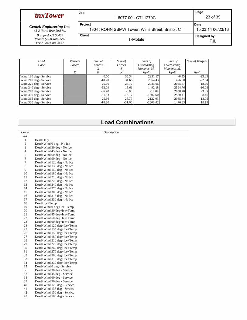
ttnnxxTToowweerr Job16077.00 - CT11270C
Page23 of 39
Centek Engineering Inc.63-2 North Branford Rd.
Project130-ft ROHN SSMW Tower, Willis Street, Bristol, CT
Date15:03:14 06/23/16
Branford, CT 06405Phone: (203) 488-0580FAX: (203) 488-8587
ClientT-Mobile
Designed byTJL
LoadCase
VerticalForces
K
Sum ofForces
XK
Sum ofForces
ZK
Sum ofOverturningMoments, Mx
kip-ft
Sum ofOverturningMoments, Mz
kip-ft
Sum of Torques
kip-ftWind 180 deg - Service 0.00 36.34 2951.17 -6.55 -23.03Wind 210 deg - Service -18.20 31.66 2564.43 1476.00 -22.04Wind 225 deg - Service -25.66 25.77 2085.96 2085.57 -18.96Wind 240 deg - Service -32.09 18.61 1492.18 2594.76 -16.08Wind 270 deg - Service -36.40 -0.00 -18.09 2958.70 -3.85Wind 300 deg - Service -31.33 -18.17 -1502.60 2550.41 8.46Wind 315 deg - Service -25.66 -25.77 -2122.03 2085.84 13.75Wind 330 deg - Service -18.20 -31.66 -2600.42 1476.33 18.19
Load CombinationsComb.
No.Description
1 Dead Only2 Dead+Wind 0 deg - No Ice3 Dead+Wind 30 deg - No Ice4 Dead+Wind 45 deg - No Ice5 Dead+Wind 60 deg - No Ice6 Dead+Wind 90 deg - No Ice7 Dead+Wind 120 deg - No Ice8 Dead+Wind 135 deg - No Ice9 Dead+Wind 150 deg - No Ice10 Dead+Wind 180 deg - No Ice11 Dead+Wind 210 deg - No Ice12 Dead+Wind 225 deg - No Ice13 Dead+Wind 240 deg - No Ice14 Dead+Wind 270 deg - No Ice15 Dead+Wind 300 deg - No Ice16 Dead+Wind 315 deg - No Ice17 Dead+Wind 330 deg - No Ice18 Dead+Ice+Temp19 Dead+Wind 0 deg+Ice+Temp20 Dead+Wind 30 deg+Ice+Temp21 Dead+Wind 45 deg+Ice+Temp22 Dead+Wind 60 deg+Ice+Temp23 Dead+Wind 90 deg+Ice+Temp24 Dead+Wind 120 deg+Ice+Temp25 Dead+Wind 135 deg+Ice+Temp26 Dead+Wind 150 deg+Ice+Temp27 Dead+Wind 180 deg+Ice+Temp28 Dead+Wind 210 deg+Ice+Temp29 Dead+Wind 225 deg+Ice+Temp30 Dead+Wind 240 deg+Ice+Temp31 Dead+Wind 270 deg+Ice+Temp32 Dead+Wind 300 deg+Ice+Temp33 Dead+Wind 315 deg+Ice+Temp34 Dead+Wind 330 deg+Ice+Temp35 Dead+Wind 0 deg - Service36 Dead+Wind 30 deg - Service37 Dead+Wind 45 deg - Service38 Dead+Wind 60 deg - Service39 Dead+Wind 90 deg - Service40 Dead+Wind 120 deg - Service41 Dead+Wind 135 deg - Service42 Dead+Wind 150 deg - Service43 Dead+Wind 180 deg - Service

ttnnxxTToowweerr Job16077.00 - CT11270C
Page24 of 39
Centek Engineering Inc.63-2 North Branford Rd.
Project130-ft ROHN SSMW Tower, Willis Street, Bristol, CT
Date15:03:14 06/23/16
Branford, CT 06405Phone: (203) 488-0580FAX: (203) 488-8587
ClientT-Mobile
Designed byTJL
Comb.No.
Description
44 Dead+Wind 210 deg - Service45 Dead+Wind 225 deg - Service46 Dead+Wind 240 deg - Service47 Dead+Wind 270 deg - Service48 Dead+Wind 300 deg - Service49 Dead+Wind 315 deg - Service50 Dead+Wind 330 deg - Service
Maximum Member ForcesSection
No.Elevation
ftComponent
TypeCondition Gov.
LoadComb.
Force
K
Major AxisMoment
kip-ft
Minor AxisMoment
kip-ftT1 130 - 120 Leg Max Tension 32 2.79 0.06 0.06
Max. Compression 19 -7.18 0.32 -0.04Max. Mx 27 -0.83 -0.34 0.03Max. My 23 -4.00 -0.01 0.45Max. Vy 27 -1.35 0.07 -0.00Max. Vx 23 2.34 0.01 -0.14
Diagonal Max Tension 29 4.28 0.00 0.00Max. Compression 29 -4.37 0.00 0.00
Max. Mx 20 4.06 0.02 0.00Max. My 32 -0.09 0.00 -0.00Max. Vy 20 -0.01 0.00 0.00Max. Vx 32 0.00 0.00 0.00
Horizontal Max Tension 22 3.23 -0.01 0.00Max. Compression 30 -3.20 0.00 0.00
Max. Mx 32 0.10 -0.01 -0.01Max. My 22 -1.76 -0.01 -0.01Max. Vy 32 -0.01 -0.01 -0.01Max. Vx 22 0.00 -0.01 -0.01
Top Girt Max Tension 22 0.75 -0.01 0.00Max. Compression 30 -0.73 -0.01 -0.00
Max. Mx 32 -0.38 -0.01 -0.00Max. My 32 -0.31 -0.01 -0.00Max. Vy 32 -0.01 -0.01 -0.00Max. Vx 32 0.00 -0.01 -0.00
Inner Bracing Max Tension 30 0.01 0.00 0.00Max. Compression 30 -0.01 0.00 0.00
Max. Mx 18 -0.00 -0.01 0.00Max. My 19 0.00 0.00 -0.00Max. Vy 18 0.01 0.00 0.00Max. Vx 19 0.00 0.00 0.00
T2 120 - 100 Leg Max Tension 22 19.25 -0.05 0.01Max. Compression 19 -27.78 0.50 -0.00
Max. Mx 27 2.77 0.78 0.06Max. My 23 -4.80 -0.02 -1.05Max. Vy 32 0.57 -0.05 -0.00Max. Vx 28 -0.82 0.01 0.06
Diagonal Max Tension 26 7.47 0.00 0.00Max. Compression 26 -7.63 0.00 0.00
Max. Mx 20 6.71 0.04 0.00Max. My 24 1.68 0.00 0.00Max. Vy 20 -0.02 0.00 0.00Max. Vx 24 -0.00 0.00 0.00
Horizontal Max Tension 26 4.71 -0.02 0.00Max. Compression 25 -4.78 -0.03 -0.00
Max. Mx 22 0.24 -0.04 -0.01Max. My 27 -0.73 -0.04 -0.01

ttnnxxTToowweerr Job16077.00 - CT11270C
Page25 of 39
Centek Engineering Inc.63-2 North Branford Rd.
Project130-ft ROHN SSMW Tower, Willis Street, Bristol, CT
Date15:03:14 06/23/16
Branford, CT 06405Phone: (203) 488-0580FAX: (203) 488-8587
ClientT-Mobile
Designed byTJL
SectionNo.
Elevationft
ComponentType
Condition Gov.Load
Comb.
Force
K
Major AxisMoment
kip-ft
Minor AxisMoment
kip-ftMax. Vy 22 -0.02 -0.04 -0.01Max. Vx 27 0.00 -0.04 -0.01
Top Girt Max Tension 32 3.40 -0.01 0.00Max. Compression 24 -3.70 -0.02 -0.00
Max. Mx 32 -1.67 -0.03 -0.01Max. My 24 -0.51 -0.01 0.01Max. Vy 32 -0.02 -0.03 -0.01Max. Vx 24 -0.00 -0.01 0.01
Inner Bracing Max Tension 24 0.06 0.00 0.00Max. Compression 24 -0.06 0.00 0.00
Max. Mx 18 -0.00 -0.01 0.00Max. My 19 0.00 0.00 -0.00Max. Vy 18 0.01 0.00 0.00Max. Vx 24 0.00 0.00 0.00
T3 100 - 80 Leg Max Tension 22 46.93 -0.17 -0.16Max. Compression 19 -62.26 0.73 -0.10
Max. Mx 27 23.03 1.06 0.02Max. My 31 -7.51 -0.05 1.40Max. Vy 27 -0.91 -0.56 0.00Max. Vx 26 -1.12 -0.02 -0.30
Diagonal Max Tension 26 10.10 0.00 0.00Max. Compression 26 -10.28 0.00 0.00
Max. Mx 20 9.89 0.06 0.00Max. My 19 0.46 0.00 -0.00Max. Vy 20 -0.03 0.00 0.00Max. Vx 19 0.00 0.00 0.00
Horizontal Max Tension 28 6.96 0.00 0.00Max. Compression 28 -6.92 -0.03 0.00
Max. Mx 32 0.60 -0.05 -0.02Max. My 24 0.28 -0.01 0.02Max. Vy 32 -0.02 -0.05 -0.02Max. Vx 30 -0.00 -0.01 0.02
Top Girt Max Tension 33 5.89 -0.02 0.00Max. Compression 25 -5.97 -0.03 -0.00
Max. Mx 22 -0.16 -0.04 -0.01Max. My 30 1.27 -0.01 0.01Max. Vy 22 -0.02 -0.04 -0.01Max. Vx 30 -0.00 -0.01 0.01
Inner Bracing Max Tension 25 0.10 0.00 0.00Max. Compression 25 -0.10 0.00 0.00
Max. Mx 18 -0.00 -0.02 0.00Max. My 24 0.00 0.00 -0.00Max. Vy 18 0.01 0.00 0.00Max. Vx 24 0.00 0.00 0.00
T4 80 - 60 Leg Max Tension 32 73.82 -0.87 -0.22Max. Compression 19 -95.47 0.82 0.04
Max. Mx 27 54.13 -0.90 -0.05Max. My 31 -10.15 -0.05 1.43Max. Vy 27 0.69 -0.90 -0.05Max. Vx 20 -1.05 -0.02 -0.67
Diagonal Max Tension 26 15.02 0.00 0.00Max. Compression 26 -15.27 0.00 0.00
Max. Mx 26 15.02 0.11 0.00Max. My 19 0.15 0.00 -0.00Max. Vy 26 0.04 0.00 0.00Max. Vx 19 0.00 0.00 0.00
Horizontal Max Tension 26 8.99 -0.04 0.00Max. Compression 26 -9.08 -0.04 0.00
Max. Mx 22 0.86 -0.07 -0.02Max. My 24 0.43 -0.01 0.02Max. Vy 22 -0.03 -0.07 -0.02

ttnnxxTToowweerr Job16077.00 - CT11270C
Page26 of 39
Centek Engineering Inc.63-2 North Branford Rd.
Project130-ft ROHN SSMW Tower, Willis Street, Bristol, CT
Date15:03:14 06/23/16
Branford, CT 06405Phone: (203) 488-0580FAX: (203) 488-8587
ClientT-Mobile
Designed byTJL
SectionNo.
Elevationft
ComponentType
Condition Gov.Load
Comb.
Force
K
Major AxisMoment
kip-ft
Minor AxisMoment
kip-ftMax. Vx 30 -0.00 -0.01 0.02
Top Girt Max Tension 26 7.53 -0.03 0.00Max. Compression 25 -7.58 -0.04 -0.00
Max. Mx 32 -1.29 -0.06 -0.02Max. My 24 0.13 -0.01 0.02Max. Vy 32 -0.03 -0.06 -0.02Max. Vx 24 -0.00 -0.01 0.02
Inner Bracing Max Tension 25 0.13 0.00 0.00Max. Compression 25 -0.13 0.00 0.00
Max. Mx 18 -0.00 -0.02 0.00Max. My 24 0.00 0.00 -0.00Max. Vy 18 0.01 0.00 0.00Max. Vx 24 0.00 0.00 0.00
T5 60 - 40 Leg Max Tension 22 107.50 -0.65 -0.09Max. Compression 19 -134.71 0.65 -0.20
Max. Mx 32 90.27 -0.69 -0.10Max. My 21 -42.15 0.10 -0.85Max. Vy 32 -0.23 -0.46 0.22Max. Vx 28 0.38 -0.03 0.59
Diagonal Max Tension 26 13.76 0.00 0.00Max. Compression 26 -14.05 0.00 0.00
Max. Mx 26 13.70 0.15 0.00Max. My 19 0.86 0.00 -0.00Max. Vy 26 -0.04 0.00 0.00Max. Vx 19 0.00 0.00 0.00
Horizontal Max Tension 26 9.09 -0.05 -0.00Max. Compression 26 -9.12 -0.05 -0.00
Max. Mx 22 1.22 -0.07 -0.01Max. My 30 0.36 -0.03 0.02Max. Vy 22 -0.03 -0.07 -0.01Max. Vx 30 -0.00 -0.03 0.02
Top Girt Max Tension 26 8.67 -0.04 0.00Max. Compression 26 -8.79 -0.04 0.00
Max. Mx 22 -0.80 -0.06 -0.02Max. My 30 0.69 -0.02 0.02Max. Vy 22 -0.03 -0.06 -0.02Max. Vx 24 -0.00 -0.02 0.02
Inner Bracing Max Tension 26 0.15 0.00 0.00Max. Compression 26 -0.15 0.00 0.00
Max. Mx 18 -0.01 -0.04 0.00Max. My 24 -0.00 0.00 -0.00Max. Vy 18 0.02 0.00 0.00Max. Vx 19 0.00 0.00 0.00
T6 40 - 20 Leg Max Tension 22 137.32 -0.58 -0.10Max. Compression 24 -171.07 0.30 -0.05
Max. Mx 19 -152.66 0.66 -0.09Max. My 21 -47.09 0.10 -0.85Max. Vy 19 0.11 0.66 -0.09Max. Vx 30 0.18 -0.36 0.85
Diagonal Max Tension 34 13.64 0.00 0.00Max. Compression 34 -14.04 0.00 0.00
Max. Mx 26 13.35 0.18 0.00Max. My 19 1.02 0.00 -0.00Max. Vy 26 -0.05 0.00 0.00Max. Vx 19 0.00 0.00 0.00
Horizontal Max Tension 34 9.62 0.00 0.00Max. Compression 34 -9.58 -0.09 -0.00
Max. Mx 22 1.54 -0.13 -0.02Max. My 30 -0.08 -0.05 0.02Max. Vy 22 -0.05 -0.13 -0.02Max. Vx 19 -0.00 -0.05 0.02
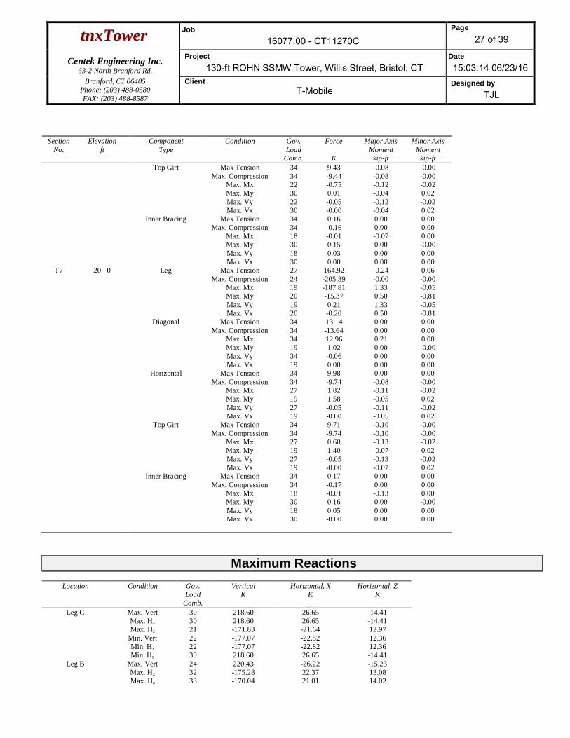
ttnnxxTToowweerr Job16077.00 - CT11270C
Page27 of 39
Centek Engineering Inc.63-2 North Branford Rd.
Project130-ft ROHN SSMW Tower, Willis Street, Bristol, CT
Date15:03:14 06/23/16
Branford, CT 06405Phone: (203) 488-0580FAX: (203) 488-8587
ClientT-Mobile
Designed byTJL
SectionNo.
Elevationft
ComponentType
Condition Gov.Load
Comb.
Force
K
Major AxisMoment
kip-ft
Minor AxisMoment
kip-ftTop Girt Max Tension 34 9.43 -0.08 -0.00
Max. Compression 34 -9.44 -0.08 -0.00Max. Mx 22 -0.75 -0.12 -0.02Max. My 30 0.01 -0.04 0.02Max. Vy 22 -0.05 -0.12 -0.02Max. Vx 30 -0.00 -0.04 0.02
Inner Bracing Max Tension 34 0.16 0.00 0.00Max. Compression 34 -0.16 0.00 0.00
Max. Mx 18 -0.01 -0.07 0.00Max. My 30 0.15 0.00 -0.00Max. Vy 18 0.03 0.00 0.00Max. Vx 30 0.00 0.00 0.00
T7 20 - 0 Leg Max Tension 27 164.92 -0.24 0.06Max. Compression 24 -205.39 -0.00 -0.00
Max. Mx 19 -187.81 1.33 -0.05Max. My 20 -15.37 0.50 -0.81Max. Vy 19 0.21 1.33 -0.05Max. Vx 20 -0.20 0.50 -0.81
Diagonal Max Tension 34 13.14 0.00 0.00Max. Compression 34 -13.64 0.00 0.00
Max. Mx 34 12.96 0.21 0.00Max. My 19 1.02 0.00 -0.00Max. Vy 34 -0.06 0.00 0.00Max. Vx 19 0.00 0.00 0.00
Horizontal Max Tension 34 9.98 0.00 0.00Max. Compression 34 -9.74 -0.08 -0.00
Max. Mx 27 1.82 -0.11 -0.02Max. My 19 1.58 -0.05 0.02Max. Vy 27 -0.05 -0.11 -0.02Max. Vx 19 -0.00 -0.05 0.02
Top Girt Max Tension 34 9.71 -0.10 -0.00Max. Compression 34 -9.74 -0.10 -0.00
Max. Mx 27 0.60 -0.13 -0.02Max. My 19 1.40 -0.07 0.02Max. Vy 27 -0.05 -0.13 -0.02Max. Vx 19 -0.00 -0.07 0.02
Inner Bracing Max Tension 34 0.17 0.00 0.00Max. Compression 34 -0.17 0.00 0.00
Max. Mx 18 -0.01 -0.13 0.00Max. My 30 0.16 0.00 -0.00Max. Vy 18 0.05 0.00 0.00Max. Vx 30 -0.00 0.00 0.00
Maximum ReactionsLocation Condition Gov.
LoadComb.
VerticalK
Horizontal, XK
Horizontal, ZK
Leg C Max. Vert 30 218.60 26.65 -14.41Max. Hx 30 218.60 26.65 -14.41Max. Hz 21 -171.83 -21.64 12.97
Min. Vert 22 -177.07 -22.82 12.36Min. Hx 22 -177.07 -22.82 12.36Min. Hz 30 218.60 26.65 -14.41
Leg B Max. Vert 24 220.43 -26.22 -15.23Max. Hx 32 -175.28 22.37 13.08Max. Hz 33 -170.04 21.01 14.02

ttnnxxTToowweerr Job16077.00 - CT11270C
Page28 of 39
Centek Engineering Inc.63-2 North Branford Rd.
Project130-ft ROHN SSMW Tower, Willis Street, Bristol, CT
Date15:03:14 06/23/16
Branford, CT 06405Phone: (203) 488-0580FAX: (203) 488-8587
ClientT-Mobile
Designed byTJL
Location Condition Gov.Load
Comb.
VerticalK
Horizontal, XK
Horizontal, ZK
Min. Vert 32 -175.28 22.37 13.08Min. Hx 24 220.43 -26.22 -15.23Min. Hz 25 205.02 -23.37 -15.31
Leg A Max. Vert 19 219.52 0.92 30.37Max. Hx 31 15.93 4.46 1.42Max. Hz 19 219.52 0.92 30.37
Min. Vert 27 -177.51 -0.85 -26.02Min. Hx 24 -85.89 -4.50 -13.15Min. Hz 27 -177.51 -0.85 -26.02
Tower Mast Reaction SummaryLoad
CombinationVertical
K
Shearx
K
Shearz
K
OverturningMoment, Mx
kip-ft
OverturningMoment, Mz
kip-ft
Torque
kip-ftDead Only 30.52 0.00 0.00 -4.63 -10.55 -0.00Dead+Wind 0 deg - No Ice 30.52 -0.00 -37.22 -2966.95 -10.39 23.84Dead+Wind 30 deg - No Ice 30.52 18.20 -31.66 -2538.52 -1464.96 22.03Dead+Wind 45 deg - No Ice 30.52 25.66 -25.77 -2069.21 -2063.20 18.94Dead+Wind 60 deg - No Ice 30.52 31.33 -18.17 -1461.42 -2519.34 14.53Dead+Wind 90 deg - No Ice 30.52 36.40 0.00 -4.48 -2919.66 3.79Dead+Wind 120 deg - No Ice 30.52 32.10 18.61 1476.63 -2561.48 -7.81Dead+Wind 135 deg - No Ice 30.52 25.66 25.77 2060.15 -2063.48 -13.80Dead+Wind 150 deg - No Ice 30.52 18.20 31.66 2529.38 -1465.30 -18.24Dead+Wind 180 deg - No Ice 30.52 0.00 36.34 2909.20 -10.78 -23.05Dead+Wind 210 deg - No Ice 30.52 -18.20 31.66 2529.22 1443.80 -22.03Dead+Wind 225 deg - No Ice 30.52 -25.66 25.77 2059.91 2042.05 -18.94Dead+Wind 240 deg - No Ice 30.52 -32.09 18.61 1476.33 2540.15 -16.04Dead+Wind 270 deg - No Ice 30.52 -36.40 -0.00 -4.85 2898.53 -3.79Dead+Wind 300 deg - No Ice 30.52 -31.33 -18.17 -1461.77 2498.39 8.52Dead+Wind 315 deg - No Ice 30.52 -25.66 -25.77 -2069.50 2042.32 13.80Dead+Wind 330 deg - No Ice 30.52 -18.20 -31.66 -2538.73 1444.13 18.24Dead+Ice+Temp 49.09 0.00 0.00 8.68 -20.34 0.00Dead+Wind 0 deg+Ice+Temp 49.09 -0.00 -51.24 -3966.01 -20.22 35.92Dead+Wind 30 deg+Ice+Temp 49.09 24.35 -42.33 -3304.37 -1924.37 36.57Dead+Wind 45 deg+Ice+Temp 49.09 34.16 -34.28 -2678.79 -2695.56 33.47Dead+Wind 60 deg+Ice+Temp 49.09 41.50 -24.04 -1879.17 -3275.34 28.00Dead+Wind 90 deg+Ice+Temp 49.09 48.71 0.00 8.86 -3828.65 14.15Dead+Wind 120 deg+Ice+Temp 49.09 44.23 25.62 1996.15 -3447.57 -2.81Dead+Wind 135 deg+Ice+Temp 49.09 34.17 34.28 2696.39 -2695.84 -14.26Dead+Wind 150 deg+Ice+Temp 49.09 24.36 42.33 3321.88 -1924.72 -22.42Dead+Wind 180 deg+Ice+Temp 49.09 0.00 48.09 3784.68 -20.62 -33.43Dead+Wind 210 deg+Ice+Temp 49.09 -24.35 42.33 3321.72 1883.55 -36.57Dead+Wind 225 deg+Ice+Temp 49.09 -34.16 34.28 2696.01 2654.67 -33.47Dead+Wind 240 deg+Ice+Temp 49.09 -44.23 25.62 1995.85 3406.59 -33.13Dead+Wind 270 deg+Ice+Temp 49.09 -48.71 -0.00 8.47 3787.90 -14.15Dead+Wind 300 deg+Ice+Temp 49.09 -41.50 -24.05 -1879.54 3234.77 5.43Dead+Wind 315 deg+Ice+Temp 49.09 -34.17 -34.28 -2679.11 2655.05 14.25Dead+Wind 330 deg+Ice+Temp 49.09 -24.36 -42.33 -3304.60 1883.91 22.42Dead+Wind 0 deg - Service 30.52 -0.00 -37.22 -2966.95 -10.39 23.84Dead+Wind 30 deg - Service 30.52 18.20 -31.66 -2538.52 -1464.96 22.03Dead+Wind 45 deg - Service 30.52 25.66 -25.77 -2069.21 -2063.20 18.94Dead+Wind 60 deg - Service 30.52 31.33 -18.17 -1461.42 -2519.34 14.53Dead+Wind 90 deg - Service 30.52 36.40 0.00 -4.48 -2919.66 3.79Dead+Wind 120 deg - Service 30.52 32.10 18.61 1476.63 -2561.48 -7.81Dead+Wind 135 deg - Service 30.52 25.66 25.77 2060.15 -2063.48 -13.80Dead+Wind 150 deg - Service 30.52 18.20 31.66 2529.38 -1465.30 -18.24

ttnnxxTToowweerr Job16077.00 - CT11270C
Page29 of 39
Centek Engineering Inc.63-2 North Branford Rd.
Project130-ft ROHN SSMW Tower, Willis Street, Bristol, CT
Date15:03:14 06/23/16
Branford, CT 06405Phone: (203) 488-0580FAX: (203) 488-8587
ClientT-Mobile
Designed byTJL
LoadCombination
Vertical
K
Shearx
K
Shearz
K
OverturningMoment, Mx
kip-ft
OverturningMoment, Mz
kip-ft
Torque
kip-ftDead+Wind 180 deg - Service 30.52 0.00 36.34 2909.20 -10.78 -23.05Dead+Wind 210 deg - Service 30.52 -18.20 31.66 2529.22 1443.80 -22.03Dead+Wind 225 deg - Service 30.52 -25.66 25.77 2059.91 2042.05 -18.94Dead+Wind 240 deg - Service 30.52 -32.09 18.61 1476.33 2540.15 -16.04Dead+Wind 270 deg - Service 30.52 -36.40 -0.00 -4.85 2898.53 -3.79Dead+Wind 300 deg - Service 30.52 -31.33 -18.17 -1461.77 2498.39 8.52Dead+Wind 315 deg - Service 30.52 -25.66 -25.77 -2069.50 2042.32 13.80Dead+Wind 330 deg - Service 30.52 -18.20 -31.66 -2538.73 1444.13 18.24
Solution Summary
LoadComb.
Sum of Applied Forces Sum of Reactions% ErrorPX
KPYK
PZK
PXK
PYK
PZK
1 0.00 -30.52 0.00 0.00 30.52 0.00 0.000%2 -0.00 -30.52 -37.22 0.00 30.52 37.22 0.000%3 18.20 -30.52 -31.66 -18.20 30.52 31.66 0.000%4 25.66 -30.52 -25.77 -25.66 30.52 25.77 0.000%5 31.33 -30.52 -18.17 -31.33 30.52 18.17 0.000%6 36.40 -30.52 0.00 -36.40 30.52 -0.00 0.000%7 32.10 -30.52 18.61 -32.10 30.52 -18.61 0.000%8 25.66 -30.52 25.77 -25.66 30.52 -25.77 0.000%9 18.20 -30.52 31.66 -18.20 30.52 -31.66 0.000%10 0.00 -30.52 36.34 -0.00 30.52 -36.34 0.000%11 -18.20 -30.52 31.66 18.20 30.52 -31.66 0.000%12 -25.66 -30.52 25.77 25.66 30.52 -25.77 0.000%13 -32.09 -30.52 18.61 32.09 30.52 -18.61 0.000%14 -36.40 -30.52 -0.00 36.40 30.52 0.00 0.000%15 -31.33 -30.52 -18.17 31.33 30.52 18.17 0.000%16 -25.66 -30.52 -25.77 25.66 30.52 25.77 0.000%17 -18.20 -30.52 -31.66 18.20 30.52 31.66 0.000%18 0.00 -49.09 0.00 0.00 49.09 0.00 0.000%19 -0.00 -49.09 -51.24 0.00 49.09 51.24 0.000%20 24.35 -49.09 -42.33 -24.35 49.09 42.33 0.000%21 34.16 -49.09 -34.28 -34.16 49.09 34.28 0.000%22 41.50 -49.09 -24.04 -41.50 49.09 24.04 0.000%23 48.71 -49.09 0.00 -48.71 49.09 -0.00 0.000%24 44.23 -49.09 25.62 -44.23 49.09 -25.62 0.000%25 34.17 -49.09 34.28 -34.17 49.09 -34.28 0.000%26 24.36 -49.09 42.33 -24.36 49.09 -42.33 0.000%27 0.00 -49.09 48.09 -0.00 49.09 -48.09 0.000%28 -24.35 -49.09 42.33 24.35 49.09 -42.33 0.000%29 -34.16 -49.09 34.28 34.16 49.09 -34.28 0.000%30 -44.23 -49.09 25.62 44.23 49.09 -25.62 0.000%31 -48.71 -49.09 -0.00 48.71 49.09 0.00 0.000%32 -41.50 -49.09 -24.05 41.50 49.09 24.05 0.000%33 -34.17 -49.09 -34.28 34.17 49.09 34.28 0.000%34 -24.36 -49.09 -42.33 24.36 49.09 42.33 0.000%35 -0.00 -30.52 -37.22 0.00 30.52 37.22 0.000%36 18.20 -30.52 -31.66 -18.20 30.52 31.66 0.000%37 25.66 -30.52 -25.77 -25.66 30.52 25.77 0.000%38 31.33 -30.52 -18.17 -31.33 30.52 18.17 0.000%39 36.40 -30.52 0.00 -36.40 30.52 -0.00 0.000%40 32.10 -30.52 18.61 -32.10 30.52 -18.61 0.000%41 25.66 -30.52 25.77 -25.66 30.52 -25.77 0.000%42 18.20 -30.52 31.66 -18.20 30.52 -31.66 0.000%43 0.00 -30.52 36.34 -0.00 30.52 -36.34 0.000%44 -18.20 -30.52 31.66 18.20 30.52 -31.66 0.000%
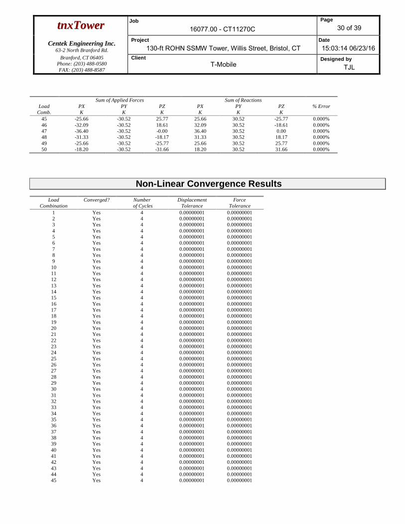
ttnnxxTToowweerr Job16077.00 - CT11270C
Page30 of 39
Centek Engineering Inc.63-2 North Branford Rd.
Project130-ft ROHN SSMW Tower, Willis Street, Bristol, CT
Date15:03:14 06/23/16
Branford, CT 06405Phone: (203) 488-0580FAX: (203) 488-8587
ClientT-Mobile
Designed byTJL
LoadComb.
Sum of Applied Forces Sum of Reactions% ErrorPX
KPYK
PZK
PXK
PYK
PZK
45 -25.66 -30.52 25.77 25.66 30.52 -25.77 0.000%46 -32.09 -30.52 18.61 32.09 30.52 -18.61 0.000%47 -36.40 -30.52 -0.00 36.40 30.52 0.00 0.000%48 -31.33 -30.52 -18.17 31.33 30.52 18.17 0.000%49 -25.66 -30.52 -25.77 25.66 30.52 25.77 0.000%50 -18.20 -30.52 -31.66 18.20 30.52 31.66 0.000%
Non-Linear Convergence ResultsLoad
CombinationConverged? Number
of CyclesDisplacement
ToleranceForce
Tolerance1 Yes 4 0.00000001 0.000000012 Yes 4 0.00000001 0.000000013 Yes 4 0.00000001 0.000000014 Yes 4 0.00000001 0.000000015 Yes 4 0.00000001 0.000000016 Yes 4 0.00000001 0.000000017 Yes 4 0.00000001 0.000000018 Yes 4 0.00000001 0.000000019 Yes 4 0.00000001 0.0000000110 Yes 4 0.00000001 0.0000000111 Yes 4 0.00000001 0.0000000112 Yes 4 0.00000001 0.0000000113 Yes 4 0.00000001 0.0000000114 Yes 4 0.00000001 0.0000000115 Yes 4 0.00000001 0.0000000116 Yes 4 0.00000001 0.0000000117 Yes 4 0.00000001 0.0000000118 Yes 4 0.00000001 0.0000000119 Yes 4 0.00000001 0.0000000120 Yes 4 0.00000001 0.0000000121 Yes 4 0.00000001 0.0000000122 Yes 4 0.00000001 0.0000000123 Yes 4 0.00000001 0.0000000124 Yes 4 0.00000001 0.0000000125 Yes 4 0.00000001 0.0000000126 Yes 4 0.00000001 0.0000000127 Yes 4 0.00000001 0.0000000128 Yes 4 0.00000001 0.0000000129 Yes 4 0.00000001 0.0000000130 Yes 4 0.00000001 0.0000000131 Yes 4 0.00000001 0.0000000132 Yes 4 0.00000001 0.0000000133 Yes 4 0.00000001 0.0000000134 Yes 4 0.00000001 0.0000000135 Yes 4 0.00000001 0.0000000136 Yes 4 0.00000001 0.0000000137 Yes 4 0.00000001 0.0000000138 Yes 4 0.00000001 0.0000000139 Yes 4 0.00000001 0.0000000140 Yes 4 0.00000001 0.0000000141 Yes 4 0.00000001 0.0000000142 Yes 4 0.00000001 0.0000000143 Yes 4 0.00000001 0.0000000144 Yes 4 0.00000001 0.0000000145 Yes 4 0.00000001 0.00000001

ttnnxxTToowweerr Job16077.00 - CT11270C
Page31 of 39
Centek Engineering Inc.63-2 North Branford Rd.
Project130-ft ROHN SSMW Tower, Willis Street, Bristol, CT
Date15:03:14 06/23/16
Branford, CT 06405Phone: (203) 488-0580FAX: (203) 488-8587
ClientT-Mobile
Designed byTJL
46 Yes 4 0.00000001 0.0000000147 Yes 4 0.00000001 0.0000000148 Yes 4 0.00000001 0.0000000149 Yes 4 0.00000001 0.0000000150 Yes 4 0.00000001 0.00000001
Maximum Tower Deflections - Service WindSection
No.Elevation
ft
Horz.Deflection
in
Gov.Load
Comb.
Tilt
°
Twist
°T1 130 - 120 5.354 35 0.3422 0.1048T2 120 - 100 4.629 35 0.3359 0.0930T3 100 - 80 3.261 35 0.2967 0.0593T4 80 - 60 2.076 35 0.2367 0.0365T5 60 - 40 1.179 35 0.1700 0.0247T6 40 - 20 0.538 35 0.1111 0.0156T7 20 - 0 0.159 35 0.0509 0.0076
Critical Deflections and Radius of Curvature - Service WindElevation
ft
Appurtenance Gov.Load
Comb.
Deflection
in
Tilt
°
Twist
°
Radius ofCurvature
ft132.00 DB806D-Y 35 5.354 0.3422 0.1048 84969131.00 PD220 35 5.354 0.3422 0.1048 84969130.00 Lightning Rod 35 5.354 0.3422 0.1048 84969125.00 LNX-6515DS 35 4.989 0.3398 0.0993 84969117.00 PA6-59 35 4.415 0.3322 0.0885 40032115.00 1142-2B 35 4.274 0.3293 0.0853 38307113.00 1142-2B 35 4.135 0.3259 0.0819 36857107.00 6 FT DISH 35 3.724 0.3138 0.0713 33099105.00 AP11-850/105N 35 3.590 0.3092 0.0678 32011104.00 AP11-850/105N 35 3.523 0.3068 0.0660 3148599.00 6 FT DISH 35 3.197 0.2940 0.0579 2768398.00 ROHN 4-ft Side Arm 35 3.132 0.2913 0.0566 2660496.00 8 FT DISH 35 3.006 0.2858 0.0539 2443586.00 PAD8-59AW 35 2.404 0.2561 0.0422 1703984.00 2' Yagi 35 2.292 0.2497 0.0402 1607075.00 Valmont T-Arm (1) 35 1.825 0.2199 0.0330 1558771.00 4 FT DISH 35 1.637 0.2063 0.0306 1666770.00 TTA 12''x6''x4'' 35 1.592 0.2029 0.0300 1696165.00 Diamond X-500A 35 1.378 0.1861 0.0273 1860158.00 DB212-1 35 1.104 0.1638 0.0240 2016854.00 DB212-1 35 0.961 0.1518 0.0223 1966546.00 DB230-2B 35 0.703 0.1286 0.0185 1855143.00 ROHN 4-ft Side Arm 35 0.618 0.1200 0.0171 1817342.00 Wind speed cups 35 0.590 0.1170 0.0166 18067
Maximum Tower Deflections - Design Wind
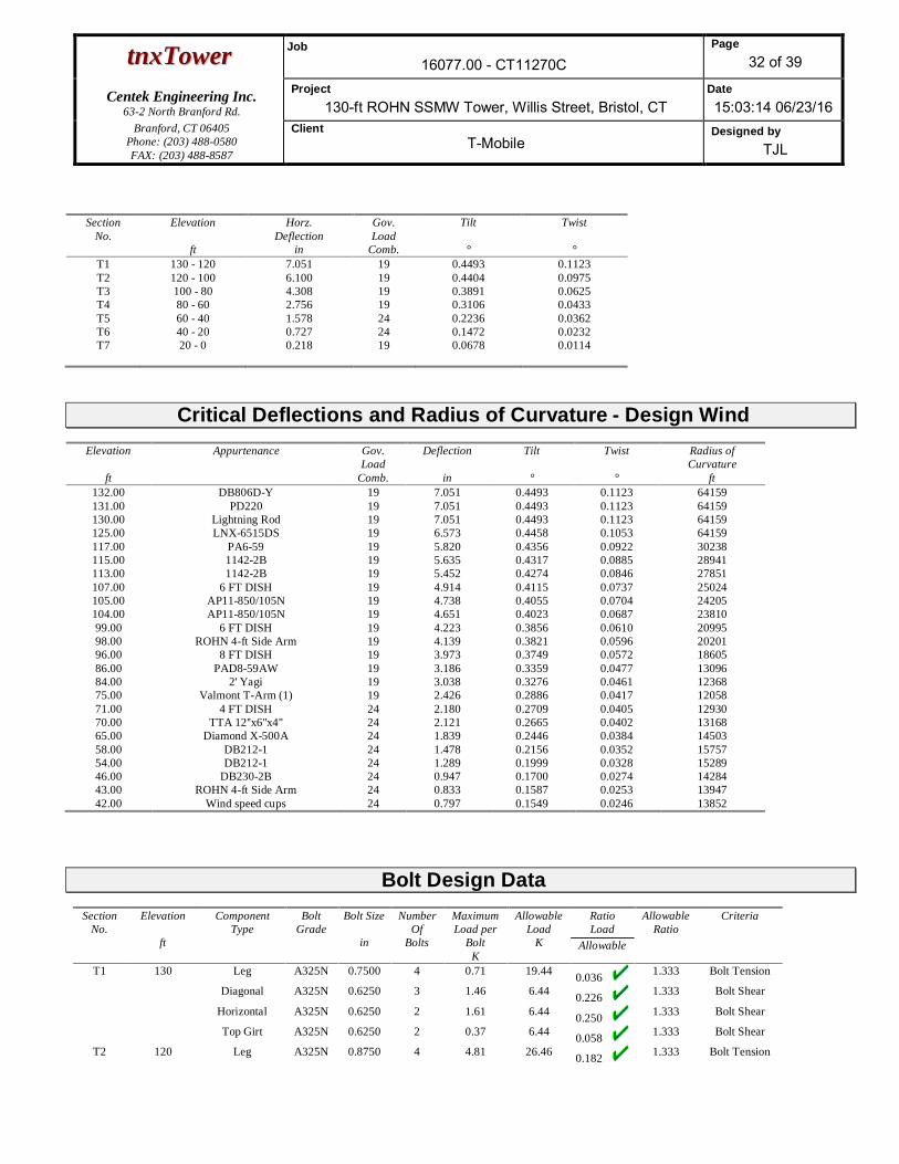
ttnnxxTToowweerr Job16077.00 - CT11270C
Page32 of 39
Centek Engineering Inc.63-2 North Branford Rd.
Project130-ft ROHN SSMW Tower, Willis Street, Bristol, CT
Date15:03:14 06/23/16
Branford, CT 06405Phone: (203) 488-0580FAX: (203) 488-8587
ClientT-Mobile
Designed byTJL
SectionNo.
Elevation
ft
Horz.Deflection
in
Gov.Load
Comb.
Tilt
°
Twist
°T1 130 - 120 7.051 19 0.4493 0.1123T2 120 - 100 6.100 19 0.4404 0.0975T3 100 - 80 4.308 19 0.3891 0.0625T4 80 - 60 2.756 19 0.3106 0.0433T5 60 - 40 1.578 24 0.2236 0.0362T6 40 - 20 0.727 24 0.1472 0.0232T7 20 - 0 0.218 19 0.0678 0.0114
Critical Deflections and Radius of Curvature - Design WindElevation
ft
Appurtenance Gov.Load
Comb.
Deflection
in
Tilt
°
Twist
°
Radius ofCurvature
ft132.00 DB806D-Y 19 7.051 0.4493 0.1123 64159131.00 PD220 19 7.051 0.4493 0.1123 64159130.00 Lightning Rod 19 7.051 0.4493 0.1123 64159125.00 LNX-6515DS 19 6.573 0.4458 0.1053 64159117.00 PA6-59 19 5.820 0.4356 0.0922 30238115.00 1142-2B 19 5.635 0.4317 0.0885 28941113.00 1142-2B 19 5.452 0.4274 0.0846 27851107.00 6 FT DISH 19 4.914 0.4115 0.0737 25024105.00 AP11-850/105N 19 4.738 0.4055 0.0704 24205104.00 AP11-850/105N 19 4.651 0.4023 0.0687 2381099.00 6 FT DISH 19 4.223 0.3856 0.0610 2099598.00 ROHN 4-ft Side Arm 19 4.139 0.3821 0.0596 2020196.00 8 FT DISH 19 3.973 0.3749 0.0572 1860586.00 PAD8-59AW 19 3.186 0.3359 0.0477 1309684.00 2' Yagi 19 3.038 0.3276 0.0461 1236875.00 Valmont T-Arm (1) 19 2.426 0.2886 0.0417 1205871.00 4 FT DISH 24 2.180 0.2709 0.0405 1293070.00 TTA 12''x6''x4'' 24 2.121 0.2665 0.0402 1316865.00 Diamond X-500A 24 1.839 0.2446 0.0384 1450358.00 DB212-1 24 1.478 0.2156 0.0352 1575754.00 DB212-1 24 1.289 0.1999 0.0328 1528946.00 DB230-2B 24 0.947 0.1700 0.0274 1428443.00 ROHN 4-ft Side Arm 24 0.833 0.1587 0.0253 1394742.00 Wind speed cups 24 0.797 0.1549 0.0246 13852
Bolt Design DataSection
No.Elevation
ft
ComponentType
BoltGrade
Bolt Size
in
NumberOf
Bolts
MaximumLoad per
BoltK
AllowableLoad
K
RatioLoad
Allowable
AllowableRatio
Criteria
T1 130 Leg A325N 0.7500 4 0.71 19.44 0.036 1.333 Bolt Tension
Diagonal A325N 0.6250 3 1.46 6.44 0.226 1.333 Bolt Shear
Horizontal A325N 0.6250 2 1.61 6.44 0.250 1.333 Bolt Shear
Top Girt A325N 0.6250 2 0.37 6.44 0.058 1.333 Bolt Shear
T2 120 Leg A325N 0.8750 4 4.81 26.46 0.182 1.333 Bolt Tension

ttnnxxTToowweerr Job16077.00 - CT11270C
Page33 of 39
Centek Engineering Inc.63-2 North Branford Rd.
Project130-ft ROHN SSMW Tower, Willis Street, Bristol, CT
Date15:03:14 06/23/16
Branford, CT 06405Phone: (203) 488-0580FAX: (203) 488-8587
ClientT-Mobile
Designed byTJL
SectionNo.
Elevation
ft
ComponentType
BoltGrade
Bolt Size
in
NumberOf
Bolts
MaximumLoad per
BoltK
AllowableLoad
K
RatioLoad
Allowable
AllowableRatio
Criteria
Diagonal A325N 0.6250 3 2.54 6.44 0.395 1.333 Bolt Shear
Horizontal A325N 0.6250 2 2.39 6.44 0.371 1.333 Bolt Shear
Top Girt A325N 0.6250 2 1.85 6.44 0.287 1.333 Bolt Shear
T3 100 Leg A325N 1.0000 4 11.73 34.56 0.340 1.333 Bolt Tension
Diagonal A325N 0.6250 3 3.43 6.44 0.532 1.333 Bolt Shear
Horizontal A325N 0.6250 2 3.48 6.44 0.540 1.333 Bolt Shear
Top Girt A325N 0.6250 2 2.98 6.44 0.463 1.333 Bolt Shear
T4 80 Leg A325N 1.0000 4 18.43 34.56 0.533 1.333 Bolt Tension
Diagonal A325N 0.6250 3 5.09 6.44 0.790 1.333 Bolt Shear
Horizontal A325N 0.6250 2 4.54 6.44 0.705 1.333 Bolt Shear
Top Girt A325N 0.6250 2 3.79 6.44 0.588 1.333 Bolt Shear
T5 60 Leg A325N 1.0000 6 17.92 34.56 0.518 1.333 Bolt Tension
Diagonal A325N 0.6250 3 4.68 6.44 0.727 1.333 Bolt Shear
Horizontal A325N 0.6250 2 4.56 6.44 0.707 1.333 Bolt Shear
Top Girt A325N 0.6250 2 4.40 6.44 0.682 1.333 Bolt Shear
T6 40 Leg A325N 1.0000 6 22.89 34.56 0.662 1.333 Bolt Tension
Diagonal A325N 0.6250 3 4.68 6.44 0.726 1.333 Bolt Shear
Horizontal A325N 0.6250 2 4.81 6.44 0.747 1.333 Bolt Shear
Top Girt A325N 0.6250 2 4.72 6.44 0.733 1.333 Bolt Shear
T7 20 Leg F1554-105
1.0000 8 20.61 32.40 0.636 1.333 Bolt Tension
Diagonal A325N 0.6250 3 4.55 6.44 0.706 1.333 Bolt Shear
Horizontal A325N 0.6250 2 4.99 6.44 0.774 1.333 Bolt Shear
Top Girt A325N 0.6250 2 4.87 6.44 0.756 1.333 Bolt Shear
Compression Checks
Leg Design Data (Compression)Section
No.Elevation
ft
Size L
ft
Lu
ft
Kl/r Fa
ksi
A
in2
ActualPK
Allow.PaK
RatioPPa
T1 130 - 120 ROHN 2.5 STD 10.00 5.00 63.3K=1.00
22.141 1.7040 -7.18 37.73 0.190
T2 120 - 100 ROHN 3 STD 20.04 6.68 68.9K=1.00
21.145 2.2285 -27.78 47.12 0.589
T3 100 - 80 ROHN 4 STD 20.04 6.68 53.1K=1.00
23.861 3.1741 -62.26 75.74 0.822
T4 80 - 60 ROHN 5 STD 20.04 10.02 64.0K=1.00
22.016 4.2999 -95.46 94.67 1.008

ttnnxxTToowweerr Job16077.00 - CT11270C
Page34 of 39
Centek Engineering Inc.63-2 North Branford Rd.
Project130-ft ROHN SSMW Tower, Willis Street, Bristol, CT
Date15:03:14 06/23/16
Branford, CT 06405Phone: (203) 488-0580FAX: (203) 488-8587
ClientT-Mobile
Designed byTJL
SectionNo.
Elevation
ft
Size L
ft
Lu
ft
Kl/r Fa
ksi
A
in2
ActualPK
Allow.PaK
RatioPPa
T5 60 - 40 ROHN 5 EH 20.06 10.03 65.4K=1.00
21.769 6.1120 -134.71 133.05 1.012
T6 40 - 20 ROHN 6 EHS 20.05 10.03 54.1K=1.00
23.705 6.7133 -171.07 159.14 1.075
T7 20 - 0 ROHN 6 EH 20.05 10.03 54.8K=1.00
23.583 8.4049 -205.39 198.21 1.036
Diagonal Design Data (Compression)Section
No.Elevation
ft
Size L
ft
Lu
ft
Kl/r Fa
ksi
A
in2
ActualPK
Allow.Pa
K
RatioPPa
T1 130 - 120 ROHN 2 STD 6.58 6.39 97.4K=1.00
15.294 1.0745 -4.37 16.43 0.266
T2 120 - 100 ROHN 2.5 STD 8.53 8.29 105.0K=1.00
13.518 1.7040 -7.63 23.04 0.331
T3 100 - 80 ROHN 2.5 STD 9.21 8.94 113.2K=1.00
11.646 1.7040 -10.19 19.85 0.514
T4 80 - 60 ROHN 2.5 X-STR 12.49 12.10 157.2K=1.00
6.043 2.2535 -15.27 13.62 1.122
T5 60 - 40 ROHN 3 STD 13.31 12.96 133.6K=1.00
8.365 2.2285 -14.02 18.64 0.752
T6 40 - 20 ROHN 3 STD 14.16 13.77 142.0K=1.00
7.403 2.2285 -13.84 16.50 0.839
T7 20 - 0 ROHN 3 STD 15.07 14.70 151.6K=1.00
6.495 2.2285 -13.49 14.47 0.932
Horizontal Design Data (Compression)Section
No.Elevation
ft
Size L
ft
Lu
ft
Kl/r Fa
ksi
A
in2
ActualPK
Allow.PaK
RatioPPa
T1 130 - 120 ROHN 1.5 STD 8.52 4.14 79.8K=1.00
19.051 0.7995 -3.20 15.23 0.210
T2 120 - 100 ROHN 2 STD 9.93 4.82 73.5K=1.00
20.285 1.0745 -4.78 21.80 0.219
T3 100 - 80 ROHN 2 STD 12.01 5.82 88.7K=1.00
17.212 1.0745 -6.92 18.50 0.374
T4 80 - 60 ROHN 2 STD 13.83 6.68 101.9K=1.00
14.260 1.0745 -9.08 15.32 0.593
T5 60 - 40 ROHN 2 STD 16.25 7.89 120.3K=1.00
10.313 1.0745 -9.12 11.08 0.823
T6 40 - 20 ROHN 2.5 STD 18.79 9.12 115.5K=1.00
11.192 1.7040 -9.58 19.07 0.502
T7 20 - 0 ROHN 2.5 STD 21.29 10.37 131.3K=1.00
8.656 1.7040 -9.74 14.75 0.660

ttnnxxTToowweerr Job16077.00 - CT11270C
Page35 of 39
Centek Engineering Inc.63-2 North Branford Rd.
Project130-ft ROHN SSMW Tower, Willis Street, Bristol, CT
Date15:03:14 06/23/16
Branford, CT 06405Phone: (203) 488-0580FAX: (203) 488-8587
ClientT-Mobile
Designed byTJL
Top Girt Design Data (Compression)Section
No.Elevation
ft
Size L
ft
Lu
ft
Kl/r Fa
ksi
A
in2
ActualPK
Allow.Pa
K
RatioPPa
T1 130 - 120 ROHN 1.5 STD 8.50 4.13 79.6K=1.00
19.091 0.7995 -0.73 15.26 0.048
T2 120 - 100 ROHN 2 STD 8.54 4.15 63.3K=1.00
22.149 1.0745 -3.70 23.80 0.155
T3 100 - 80 ROHN 2 STD 10.63 5.17 78.8K=1.00
19.258 1.0745 -5.97 20.69 0.288
T4 80 - 60 ROHN 2 STD 12.71 6.17 94.0K=1.00
16.062 1.0745 -7.58 17.26 0.439
T5 60 - 40 ROHN 2 STD 14.96 7.25 110.5K=1.00
12.233 1.0745 -8.79 13.14 0.669
T6 40 - 20 ROHN 2.5 STD 17.54 8.54 108.2K=1.00
12.766 1.7040 -9.44 21.75 0.434
T7 20 - 0 ROHN 2.5 STD 20.04 9.74 123.4K=1.00
9.802 1.7040 -9.73 16.70 0.583
Inner Bracing Design Data (Compression)Section
No.Elevation
ft
Size L
ft
Lu
ft
Kl/r Fa
ksi
A
in2
ActualPK
Allow.Pa
K
RatioPPa
T1 130 - 120 L2x2x1/8 4.25 4.25 128.3K=1.00
9.074 0.4844 -0.01 4.39 0.003
T2 120 - 100 L2x2x1/8 4.27 4.27 128.9K=1.00
8.985 0.4844 -0.06 4.35 0.015
T3 100 - 80 L2x2x1/8 5.31 5.31 160.4K=1.00
5.807 0.4844 -0.10 2.81 0.037
T4 80 - 60 L2x2x1/8 6.35 6.35 191.8K=1.00
4.059 0.4844 -0.13 1.97 0.067
T5 60 - 40 L2 1/2x2 1/2x3/16 7.48 7.48 181.3K=1.00
4.542 0.9020 -0.15 4.10 0.037
T6 40 - 20 L3x3x3/16 8.77 8.77 176.6K=1.00
4.789 1.0900 -0.16 5.22 0.031
T7 20 - 0 L3 1/2x3 1/2x1/4 10.02 10.02 173.3K=1.00
4.974 1.6900 -0.17 8.41 0.020
Tension Checks
Leg Design Data (Tension)

ttnnxxTToowweerr Job16077.00 - CT11270C
Page36 of 39
Centek Engineering Inc.63-2 North Branford Rd.
Project130-ft ROHN SSMW Tower, Willis Street, Bristol, CT
Date15:03:14 06/23/16
Branford, CT 06405Phone: (203) 488-0580FAX: (203) 488-8587
ClientT-Mobile
Designed byTJL
SectionNo.
Elevation
ft
Size L
ft
Lu
ft
Kl/r Fa
ksi
A
in2
ActualPK
Allow.PaK
RatioPPa
T1 130 - 120 ROHN 2.5 STD 10.00 5.00 63.3 30.000 1.7040 2.83 51.12 0.055
T2 120 - 100 ROHN 3 STD 20.04 6.68 68.9 30.000 2.2285 19.25 66.85 0.288
T3 100 - 80 ROHN 4 STD 20.04 6.68 53.1 30.000 3.1741 46.93 95.22 0.493
T4 80 - 60 ROHN 5 STD 20.04 10.02 64.0 30.000 4.2999 73.71 129.00 0.571
T5 60 - 40 ROHN 5 EH 20.06 10.03 65.4 30.000 6.1120 107.50 183.36 0.586
T6 40 - 20 ROHN 6 EHS 20.05 10.03 54.1 30.000 6.7133 137.32 201.40 0.682
T7 20 - 0 ROHN 6 EH 20.05 10.03 54.8 30.000 8.4049 164.92 252.15 0.654
Diagonal Design Data (Tension)Section
No.Elevation
ft
Size L
ft
Lu
ft
Kl/r Fa
ksi
A
in2
ActualPK
Allow.PaK
RatioPPa
T1 130 - 120 ROHN 2 STD 6.58 6.39 97.4 30.000 1.0745 4.28 32.24 0.133
T2 120 - 100 ROHN 2.5 STD 8.53 8.29 105.0 30.000 1.7040 7.47 51.12 0.146
T3 100 - 80 ROHN 2.5 STD 8.98 8.70 110.2 30.000 1.7040 10.10 51.12 0.198
T4 80 - 60 ROHN 2.5 X-STR 12.49 12.10 157.2 30.000 2.2535 15.02 67.61 0.222
T5 60 - 40 ROHN 3 STD 12.89 12.54 129.3 30.000 2.2285 13.76 66.85 0.206
T6 40 - 20 ROHN 3 STD 13.73 13.34 137.5 30.000 2.2285 13.64 66.85 0.204
T7 20 - 0 ROHN 3 STD 14.61 14.24 146.9 30.000 2.2285 13.14 66.85 0.197
Horizontal Design Data (Tension)Section
No.Elevation
ft
Size L
ft
Lu
ft
Kl/r Fa
ksi
A
in2
ActualPK
Allow.PaK
RatioPPa
T1 130 - 120 ROHN 1.5 STD 8.52 4.14 79.8 30.000 0.7995 3.23 23.98 0.135
T2 120 - 100 ROHN 2 STD 9.93 4.82 73.5 30.000 1.0745 4.71 32.24 0.146
T3 100 - 80 ROHN 2 STD 12.01 5.82 88.7 30.000 1.0745 6.96 32.24 0.216
T4 80 - 60 ROHN 2 STD 13.83 6.68 101.9 30.000 1.0745 8.99 32.24 0.279

ttnnxxTToowweerr Job16077.00 - CT11270C
Page37 of 39
Centek Engineering Inc.63-2 North Branford Rd.
Project130-ft ROHN SSMW Tower, Willis Street, Bristol, CT
Date15:03:14 06/23/16
Branford, CT 06405Phone: (203) 488-0580FAX: (203) 488-8587
ClientT-Mobile
Designed byTJL
SectionNo.
Elevation
ft
Size L
ft
Lu
ft
Kl/r Fa
ksi
A
in2
ActualPK
Allow.PaK
RatioPPa
T5 60 - 40 ROHN 2 STD 16.25 7.89 120.3 30.000 1.0745 9.09 32.24 0.282
T6 40 - 20 ROHN 2.5 STD 18.79 9.12 115.5 30.000 1.7040 9.62 51.12 0.188
T7 20 - 0 ROHN 2.5 STD 21.29 10.37 131.3 30.000 1.7040 9.98 51.12 0.195
Top Girt Design Data (Tension)Section
No.Elevation
ft
Size L
ft
Lu
ft
Kl/r Fa
ksi
A
in2
ActualPK
Allow.Pa
K
RatioPPa
T1 130 - 120 ROHN 1.5 STD 8.50 4.13 79.6 30.000 0.7995 0.75 23.98 0.031
T2 120 - 100 ROHN 2 STD 8.54 4.15 63.3 30.000 1.0745 3.40 32.24 0.105
T3 100 - 80 ROHN 2 STD 10.63 5.17 78.8 30.000 1.0745 5.89 32.24 0.183
T4 80 - 60 ROHN 2 STD 12.71 6.17 94.0 30.000 1.0745 7.53 32.24 0.234
T5 60 - 40 ROHN 2 STD 14.96 7.25 110.5 30.000 1.0745 8.67 32.24 0.269
T6 40 - 20 ROHN 2.5 STD 17.54 8.54 108.2 30.000 1.7040 9.43 51.12 0.184
T7 20 - 0 ROHN 2.5 STD 20.04 9.74 123.4 30.000 1.7040 9.71 51.12 0.190
Inner Bracing Design Data (Tension)Section
No.Elevation
ft
Size L
ft
Lu
ft
Kl/r Fa
ksi
A
in2
ActualPK
Allow.PaK
RatioPPa
T1 130 - 120 L2x2x1/8 4.25 4.25 81.4 21.600 0.4844 0.01 10.46 0.001
T2 120 - 100 L2x2x1/8 4.27 4.27 81.8 21.600 0.4844 0.06 10.46 0.006
T3 100 - 80 L2x2x1/8 5.31 5.31 101.8 21.600 0.4844 0.10 10.46 0.010
T4 80 - 60 L2x2x1/8 6.35 6.35 121.8 21.600 0.4844 0.13 10.46 0.013
T5 60 - 40 L2 1/2x2 1/2x3/16 7.48 7.48 115.4 21.600 0.9020 0.15 19.48 0.008
T6 40 - 20 L3x3x3/16 8.77 8.77 112.1 21.600 1.0900 0.16 23.54 0.007
T7 20 - 0 L3 1/2x3 1/2x1/4 10.02 10.02 110.3 21.600 1.6900 0.17 36.50 0.005

ttnnxxTToowweerr Job16077.00 - CT11270C
Page38 of 39
Centek Engineering Inc.63-2 North Branford Rd.
Project130-ft ROHN SSMW Tower, Willis Street, Bristol, CT
Date15:03:14 06/23/16
Branford, CT 06405Phone: (203) 488-0580FAX: (203) 488-8587
ClientT-Mobile
Designed byTJL
SectionNo.
Elevation
ft
Size L
ft
Lu
ft
Kl/r Fa
ksi
A
in2
ActualPK
Allow.PaK
RatioPPa
Section Capacity TableSection
No.Elevation
ftComponent
TypeSize Critical
ElementPK
SF*PallowK
%Capacity
PassFail
T1 130 - 120 Leg ROHN 2.5 STD 3 -7.18 50.29 14.3 PassT2 120 - 100 Leg ROHN 3 STD 30 -27.78 62.81 44.2 PassT3 100 - 80 Leg ROHN 4 STD 69 -62.26 100.96 61.7 PassT4 80 - 60 Leg ROHN 5 STD 108 -95.46 126.19 75.7 PassT5 60 - 40 Leg ROHN 5 EH 135 -134.71 177.35 76.0 PassT6 40 - 20 Leg ROHN 6 EHS 161 -171.07 212.13 80.6 PassT7 20 - 0 Leg ROHN 6 EH 188 -205.39 264.22 77.7 PassT1 130 - 120 Diagonal ROHN 2 STD 15 -4.37 21.91 20.0 PassT2 120 - 100 Diagonal ROHN 2.5 STD 38 -7.63 30.71 24.8
29.6 (b)Pass
T3 100 - 80 Diagonal ROHN 2.5 STD 81 -10.19 26.45 38.539.9 (b)
Pass
T4 80 - 60 Diagonal ROHN 2.5 X-STR 116 -15.27 18.15 84.1 PassT5 60 - 40 Diagonal ROHN 3 STD 143 -14.02 24.85 56.4 PassT6 40 - 20 Diagonal ROHN 3 STD 171 -13.84 21.99 62.9 PassT7 20 - 0 Diagonal ROHN 3 STD 198 -13.49 19.29 69.9 PassT1 130 - 120 Horizontal ROHN 1.5 STD 13 -3.20 20.30 15.8
18.8 (b)Pass
T2 120 - 100 Horizontal ROHN 2 STD 37 -4.78 29.06 16.427.8 (b)
Pass
T3 100 - 80 Horizontal ROHN 2 STD 79 -6.92 24.65 28.140.5 (b)
Pass
T4 80 - 60 Horizontal ROHN 2 STD 115 -9.08 20.43 44.552.9 (b)
Pass
T5 60 - 40 Horizontal ROHN 2 STD 142 -9.12 14.77 61.7 PassT6 40 - 20 Horizontal ROHN 2.5 STD 169 -9.58 25.42 37.7
56.0 (b)Pass
T7 20 - 0 Horizontal ROHN 2.5 STD 196 -9.74 19.66 49.558.1 (b)
Pass
T1 130 - 120 Top Girt ROHN 1.5 STD 6 -0.73 20.34 3.64.3 (b)
Pass
T2 120 - 100 Top Girt ROHN 2 STD 32 -3.70 31.73 11.721.5 (b)
Pass
T3 100 - 80 Top Girt ROHN 2 STD 71 -5.97 27.58 21.634.8 (b)
Pass
T4 80 - 60 Top Girt ROHN 2 STD 110 -7.58 23.01 32.944.1 (b)
Pass
T5 60 - 40 Top Girt ROHN 2 STD 137 -8.79 17.52 50.251.2 (b)
Pass
T6 40 - 20 Top Girt ROHN 2.5 STD 164 -9.44 29.00 32.655.0 (b)
Pass
T7 20 - 0 Top Girt ROHN 2.5 STD 191 -9.73 22.27 43.756.7 (b)
Pass
T1 130 - 120 Inner Bracing L2x2x1/8 26 -0.01 5.86 0.2 PassT2 120 - 100 Inner Bracing L2x2x1/8 64 -0.06 5.80 1.1 PassT3 100 - 80 Inner Bracing L2x2x1/8 103 -0.10 3.75 2.8 PassT4 80 - 60 Inner Bracing L2x2x1/8 131 -0.13 2.62 5.0 PassT5 60 - 40 Inner Bracing L2 1/2x2 1/2x3/16 157 -0.15 5.46 2.8 PassT6 40 - 20 Inner Bracing L3x3x3/16 184 -0.16 6.96 2.3 PassT7 20 - 0 Inner Bracing L3 1/2x3 1/2x1/4 212 -0.17 11.21 1.5 Pass
Summary

ttnnxxTToowweerr Job16077.00 - CT11270C
Page39 of 39
Centek Engineering Inc.63-2 North Branford Rd.
Project130-ft ROHN SSMW Tower, Willis Street, Bristol, CT
Date15:03:14 06/23/16
Branford, CT 06405Phone: (203) 488-0580FAX: (203) 488-8587
ClientT-Mobile
Designed byTJL
SectionNo.
Elevationft
ComponentType
Size CriticalElement
PK
SF*Pallow
K%
CapacityPassFail
Leg (T6) 80.6 PassDiagonal
(T4)84.1 Pass
Horizontal(T5)
61.7 Pass
Top Girt(T7)
56.7 Pass
InnerBracing (T4)
5.0 Pass
Bolt Checks 59.3 PassRATING = 84.1 Pass
Program Version 7.0.5.1 - 2/1/2016 File:J:/Jobs/1607700.WI/Backup Documentation/Rev (1)/ERI Files/130-ft ROHN SSMW Lattice Bristol.eri

Subject:
Location:
Rev. 1: 6/23/16
Anchor Bolt Analysis
Bristol, CT
Prepared by: T.J.L. Checked by: C.F.C.Job No. 16077.00
Tower Anchor Bolt Analysis
Max Leg Reactions:
Uplift = Uplift 178 kips×:= (User Input)
Shear = Shear 30 kips×:= (User Input)
Compression = Compression 220 kips×:= (User Input)
Anchor Bolt Data:
Use ASTM F1554-105
Number of Anchor Bolts = N 8:= (User Input)
Bolt Ultimate Strength = Fu 125ksi:= (User Input)
Bolt Yield Strength = Fy 105ksi:= (User Input)
Diameter of Bolts = D 1.0in:= (User Input)
Threads per Inch = n 8:= (User Input)
Coefficient of Friction = μ 0.55:= (User Input) (ASCE 10-97 pg. 23)
Anchor Bolt Area:
Net Area of Bolt = Anπ4
D0.974 in×
n-æç
èö÷ø
2× 0.606 in
2×=:= (ASCE 10-97 Eq. 7.4-3)
Check Anchor Bolt Area: Based on the ASCE 10-97 Design of Lat ticedSteel Transmission S tructures
Required Area = As1UpliftFy
Shearμ .85× Fy×
+ 2.3 in2
×=:= (ASCE 10-97 Eq. 7.4-2)
As2Shear 0.3 Compression×( )-
μ .85× Fy×éêë
ùúû
0.733- in2
×=:= (ASCE 10-97Eq. 7.4-4)
Provided Area = Asprovided An N× 4.8 in2
×=:=
Condition1 ifAs1
Asprovided1.00£ "OK", "Overstressed",
æçè
ö÷ø
:=
Condition1 "OK"=
Condition2 ifAs2
Asprovided1.00£ "OK", "Overstressed",
æçè
ö÷ø
:=
Condition2 "OK"=
Tower Anchor bolts.xmcd.xmcd Page 3.4-1

Subject:
Location:
Rev. 1: 6/23/16
FOUNDATION ANALYSIS
Bristol, CT
Prepared by: T.J.L. Checked by: C.F.C.Job No. 16077.00
Mat Foundation Analysis:
Input Data:
Tower Data
Overturning Moment = OM 3984 ft× kips×:= (User Input from tnxTower)
Shear Force = St 51 kip× 51 kip×=:= (User Input from tnxTower)
Axial Force = WTt 49 kip× 49 kip×=:= (User Input from tnxTower)
Max Compression Force = Ct 220 kip×:= (User Input from tnxTower)
Max Uplift Force = Ut 178 kip×:= (User Input from tnxTower)
Tower Height = Ht 130 ft×:= (User Input)
Tower Width = Wt 17.3 ft×:= (User Input)
Tower Position on Foundation (1=offset, 2=centered) = Post 2:= (User Input)
Footing Data:
Overall Depth of Footing = Df 3.5 ft×:= (User Input)
Thickness of Footing = Tf 4.0 ft×:= (User Input)
Width of Footing = Wf 31.0 ft×:= (User Input)
Length of Pier = Lp 0 ft×:= (User Input)
Extension of Pier Above Grade = Lpag 0 ft×:= (User Input)
Diameter of Pier = dp 0 ft×:= (User Input)
Material Properties:
Concrete Compressive Strength = fc 4000 psi×:= (User Input)
Steel Reinforcment Yield S trength = fy 60000 psi×:= (User Input)
Internal Friction Angle of Soil = Φs 34 deg×:= (User Input)
Allowable Soil Bearing Capacity = qs 6000 psf×:= (User Input)
Unit Weight of Soil = γsoil 100 pcf×:= (User Input)
Unit Weight of Concrete = γconc 150 pcf×:= (User Input)
Foundation Bouyancy = Bouyancy 0:= (User Input) (Yes=1 / No=0)
Depth to Neglect = n 0 ft×:= (User Input)
Cohesion of Clay Type Soil = c 0 ksf×:= (User Input) (Use 0 for Sandy Soil)
Seismic Zone Factor = Z 2:= (User Input) (UBC-1997 Fig 23-2)
Coefficient of Friction Between Concrete = μ 0.45:= (User Input)
Mat Foundation.xmcd.xmcd Page 3.5-1
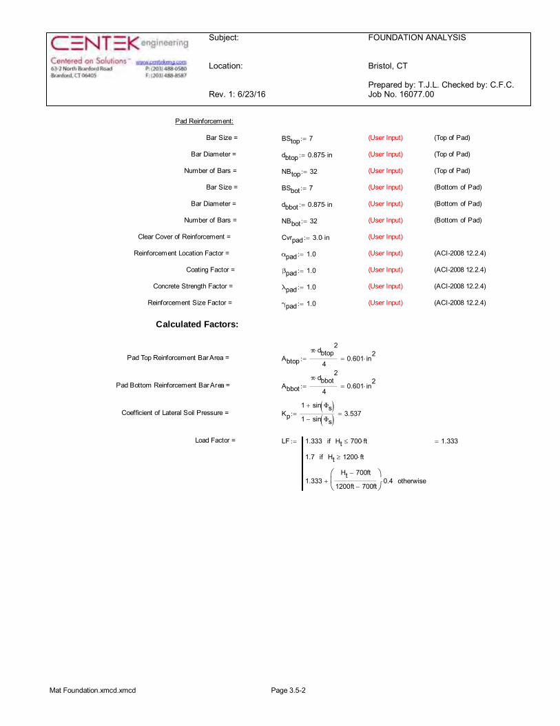
Subject:
Location:
Rev. 1: 6/23/16
FOUNDATION ANALYSIS
Bristol, CT
Prepared by: T.J.L. Checked by: C.F.C.Job No. 16077.00
Pad Reinforcement:
Bar Size = BStop 7:= (User Input) (Top of Pad)
Bar Diameter = dbtop 0.875 in×:= (User Input) (Top of Pad)
Number of Bars = NBtop 32:= (User Input) (Top of Pad)
Bar Size = BSbot 7:= (User Input) (Bottom of Pad)
Bar Diameter = dbbot 0.875 in×:= (User Input) (Bottom of Pad)
Number of Bars = NBbot 32:= (User Input) (Bottom of Pad)
Clear Cover of Reinforcement = Cvrpad 3.0 in×:= (User Input)
Reinforcement Location Factor = αpad 1.0:= (User Input) (ACI-2008 12.2.4)
Coating Factor = βpad 1.0:= (User Input) (ACI-2008 12.2.4)
Concrete Strength Factor = λpad 1.0:= (User Input) (ACI-2008 12.2.4)
Reinforcement Size Factor = γpad 1.0:= (User Input) (ACI-2008 12.2.4)
Calculated Factors:
Pad Top Reinforcement Bar Area = Abtopπ dbtop
2×
40.601 in
2×=:=
Pad Bottom Reinforcement Bar Area = Abbotπ dbbot
2×
40.601 in
2×=:=
Coefficient of Lateral Soil Pressure = Kp1 sin Φs( )+
1 sin Φs( )-3.537=:=
Load Factor = LF 1.333 Ht 700 ft×£if
1.7 Ht 1200 ft׳if
1.333Ht 700ft-
1200ft 700ft-
æçè
ö÷ø
0.4×+ otherwise
1.333=:=
Mat Foundation.xmcd.xmcd Page 3.5-2

Subject:
Location:
Rev. 1: 6/23/16
FOUNDATION ANALYSIS
Bristol, CT
Prepared by: T.J.L. Checked by: C.F.C.Job No. 16077.00
Stability of Footing:
Adjusted Concrete Unit Weight = γc if Bouyancy 1= γconc 62.4pcf-, γconc, ( ) 150 pcf×=:=
Adjusted Soil Unit Weight = γs if Bouyancy 1= γsoil 62.4pcf-, γsoil, ( ) 100 pcf×=:=
Passive Pressure = Ppn Kp γs× n× c 2× Kp×+ 0 ksf×=:=
Ppt Kp γs× Df Tf-( )× c 2× Kp×+ 0.177- ksf×=:=
Ptop if n Df Tf-( )< Ppt, Ppn, éë ùû 0 ksf×=:=
Pbot Kp γs× Df× c 2× Kp×+ 1.238 ksf×=:=
PavePtop Pbot+
20.619 ksf×=:=
Tp if n Df Tf-( )< Tf, Df n-( ), éë ùû 3.5=:=
Ap Wf Tp× 108.5=:=
Ultimate Shear = Su Pave Ap× 67.161 kip×=:=
Weight of Concrete Pad = WTpad Wf2
Tf×æè
öø γc× 576.6 kip×=:=
Weight of Concrete Piers = WTpier 3 Lpdp
2π×
4×
æççè
ö÷÷øγc×
éêêë
ùúúû
× 0 kip×=:=
Total Weight of Concrete = WTc WTpad WTpier+ 577 kip×=:=
Weight of Soil Above Footing = WTs1 Wf2
3dp
2π×
4×-
æççè
ö÷÷ø
Lp Lpag-( )× γs× 0 kip×=:=
Weight of Soil Back Face = WTs2tan Φs( ) Df( )2
×
2Wf×
éêêë
ùúúûγs× 13 kip×=:=
Tower Offset = Xt1Wf2
Wt cos 30 deg×( )×( )2
-éêë
ùúû
:= Xt2Wf2
Wt cos 30 deg×( )×( )3
-:=
Xt if Post Xt1, Xt2, ( ) 8.009=:=
XoffWf2
Wt cos 30 deg×( )×( )3
Xt+éêë
ùúû
- 2.497=:=
Resisting Moment = Mr WTc WTs1+( )Wf2
× SuTf3
×+ WTs2 Wftan Φs( ) Lp Lpag-( )×
3+
éêë
ùúû
×+ 9424 kip×=:=
Overturning Moment = Mot OM St Lp Tf+( )×+ 4188 kip ft××=:=
Factor of Safety Actual = FSMrMot
2.25=:=
Factor of Safety Required = FSreq 2:=
OverTurning_Moment_Check if FS FSreq³ "Okay", "No Good", ( ):=
OverTurning_Moment_Check "Okay"=
Mat Foundation.xmcd.xmcd Page 3.5-3

Subject:
Location:
Rev. 1: 6/23/16
FOUNDATION ANALYSIS
Bristol, CT
Prepared by: T.J.L. Checked by: C.F.C.Job No. 16077.00
Bearing Pressure Caused by Footing:
Total Load = Loadtot WTc WTs1+ WTt+ 626 kip×=:=
Area of the Mat = Amat Wf2
961=:=
Section Modulus of Mat = SWf
3
64965.17 ft
3×=:=
Maximum Pressure in Mat = PmaxLoadtotAmat
MotS
+ 1.494 ksf×=:=
Max_Pressure_Check if Pmax qs< "Okay", "No Good", ( ):=
Max_Pressure_Check "Okay"=
Minimum Pressure in Mat = PminLoadtotAmat
MotS
- 0.192- ksf×=:=
Min_Pressure_Check if Pmin 0³( ) Pmin qs<( )× "Okay", "No Good", éë ùû:=
Min_Pressure_Check "No Good"=
Distance to Resultant of Pressure Distribution = XpPmax
Pmax Pmin-
Wf
13
× 9.154=:=
Distance to Kern = XkWf6
5.167=:= Since Resultant Force is Not in Kern, Area towhich Pressure is Applied Must be Reduced.
Eccentricity = eMot
Loadtot6.694=:=
Adjusted Soil Pressure = Pa2 Loadtot×
3 Wf×Wf2
e-æçè
ö÷ø
×
1.528 ksf×=:=
qadj if Pmin 0< Pa, Pmax, ( ) 1.528 ksf×=:=
Pressure_Check if qadj qs< "Okay", "No Good", ( ):=
Pressure_Check "Okay"=
Mat Foundation.xmcd.xmcd Page 3.5-4

Subject:
Location:
Rev. 1: 6/23/16
FOUNDATION ANALYSIS
Bristol, CT
Prepared by: T.J.L. Checked by: C.F.C.Job No. 16077.00
Steel Reinforcement in Pad:
Required Reinforcement for Bending:
Strength Reduction Factor = ϕm .90:= (ACI-2008 9.3.2.1)
MnT LF Ut Wt sin 60 deg×( )×dp2
-æçè
ö÷ø
× St Df Lpag+( )×+éêë
ùúû
× WTt Xoff×- 3670 ft k××=:=
MnS 1-12
Wf2
Wt3
cos 30 deg×( )×+dp2
-æçè
ö÷ø
2
× Wt× γs Tp Tf-( )×éë ùû× WTs2Wf2
Wt3
cos 30 deg×( )×+dp2
- Df n-( ) tan Φs( )×+éêë
ùúû
×+
éêêë
ùúúû
× 111.054-=:=
MnC 1-12
Wf2
Wt3
cos 30 deg×( )×+dp2
-æçè
ö÷ø
2
× Wt× γc Tf×( )×
éêêë
ùúúû
×:=
Design Moment = MnMnT MnS+ MnC+
ϕm1532.88 kips ft××=:=
β 0.85 2500 psi× fc£ 4000 psi×£if
0.65 fc 8000 psi×>if
0.85
fcpsi
4000-æçè
ö÷ø
1000
éêêë
ùúúû
0.5×-
éêêë
ùúúû
éêêë
ùúúû
otherwise
0.85=:=
(ACI-200810.2.7.3)
beff Wt cos 30 deg×( )× dp+ 179.787 in×=:=
d Tf Cvrpad- dbbot- 44.125 in×=:=
AsMnfy d×( ) 6.948 in
2×=:=
aAs fy×
β fc× beff×0.682 in×=:=
AsMn
fy da2
-æçè
ö÷ø
×
7.002 in2
×=:=
ρAs
beff d×0.00088=:=
Mat Foundation.xmcd.xmcd Page 3.5-5
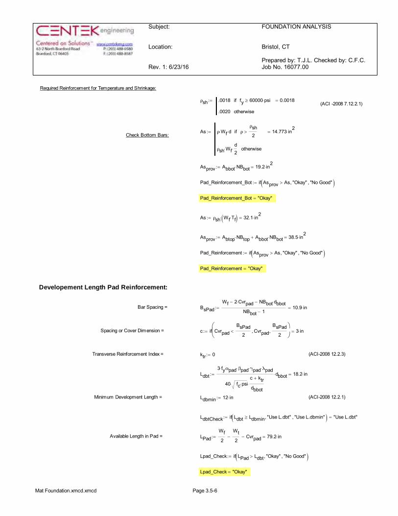
Subject:
Location:
Rev. 1: 6/23/16
FOUNDATION ANALYSIS
Bristol, CT
Prepared by: T.J.L. Checked by: C.F.C.Job No. 16077.00
Required Reinforcement for Temperature and Shrinkage:
ρsh .0018 fy 60000 psi׳if
.0020 otherwise
0.0018=:=(ACI -2008 7.12.2.1)
As ρ Wf× d× ρρsh2
>if
ρsh Wf×d2
× otherwise
14.773 in2
×=:=Check Bottom Bars:
Asprov Abbot NBbot× 19.2 in2
×=:=
Pad_Reinforcement_Bot if Asprov As> "Okay", "No Good", ( ):=
Pad_Reinforcement_Bot "Okay"=
As ρsh Wf Tf×( )× 32.1 in2
×=:=
Asprov Abtop NBtop× Abbot NBbot×+ 38.5 in2
×=:=
Pad_Reinforcement if Asprov As> "Okay", "No Good", ( ):=
Pad_Reinforcement "Okay"=
Developement Length Pad Reinforcement:
Bar Spacing = BsPadWf 2 Cvrpad×- NBbot dbbot×-
NBbot 1-10.9 in×=:=
Spacing or Cover Dimension = c if CvrpadBsPad
2< Cvrpad,
BsPad2
, æçè
ö÷ø
3 in×=:=
Transverse Reinforcement Index = ktr 0:= (ACI-2008 12.2.3)
Ldbt3 fy× αpad βpad× γpad× λpad×
40 fc psi××c ktr+
dbbot×
dbbot× 18.2 in×=:=
Minimum Development Length = Ldbmin 12 in×:= (ACI-2008 12.2.1)
LdbtCheck if Ldbt Ldbmin³ "Use L.dbt", "Use L.dbmin", ( ) "Use L.dbt"=:=
Available Length in Pad = LPadWf2
Wt2
- Cvrpad- 79.2 in×=:=
Lpad_Check if LPad Ldbt> "Okay", "No Good", ( ):=
Lpad_Check "Okay"=
Mat Foundation.xmcd.xmcd Page 3.5-6
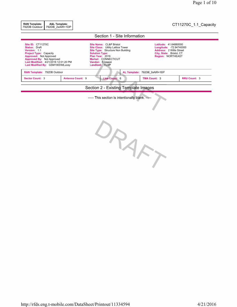
Section 1 - Site Information
RAN Template:792DB Outdoor
A&L Template:792DB_2xAIR+1DP
CT11270C_1.1_Capacity
Site ID: CT11270C Status: Draft Version: 1.1 Project Type: Capacity Approved: Not Approved Approved By: Not Approved Last Modified: 4/21/2016 12:01:20 PM Last Modified By: GSM1900\MLucey
Site Name: CL&P Bristol Site Class: Utility Lattice Tower Site Type: Structure Non Building Solution Type:Plan Year: 2016 Market: CONNECTICUT
Latitude: 41.64880000 Longitude: -72.94740000 Address: 2 Willis Street City, State: Bristol, CT Region: NORTHEAST
RAN Template: 792DB Outdoor
Sector Count: 3 Antenna Count: 9 RRU Count: 3
Page 1 of 10
4/21/2016http://rfds.eng.t-mobile.com/DataSheet/Printout/11334594

Section 3 - Proposed Template Images
792DB_2xAIR+1DP.png
Notes:
Page 2 of 10
4/21/2016http://rfds.eng.t-mobile.com/DataSheet/Printout/11334594

Section 4 - Siteplan Images
----- This section is intentionally blank. -----
Page 3 of 10
4/21/2016http://rfds.eng.t-mobile.com/DataSheet/Printout/11334594
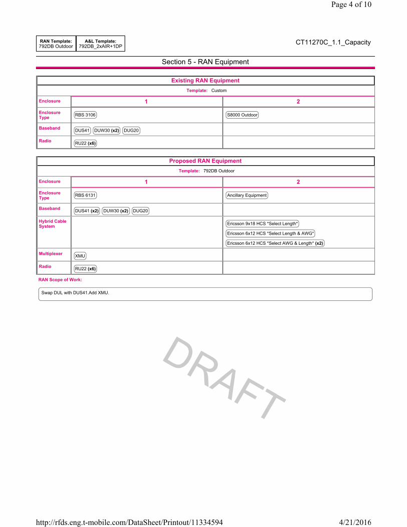
Section 5 - RAN Equipment
RAN Template:792DB Outdoor
A&L Template:792DB_2xAIR+1DP
CT11270C_1.1_Capacity
Existing RAN EquipmentTemplate: Custom
Enclosure 1 2
Enclosure Type RBS 3106 S8000 Outdoor
Baseband DUS41 DUW30 (x2) DUG20
Radio RU22 (x6)
Proposed RAN EquipmentTemplate: 792DB Outdoor
Enclosure 1 2
Enclosure Type RBS 6131 Ancillary Equipment
Baseband DUS41 (x2) DUW30 (x2) DUG20
Hybrid Cable System Ericsson 9x18 HCS *Select Length*
Ericsson 6x12 HCS *Select Length & AWG*
Ericsson 6x12 HCS *Select AWG & Length* (x2)
Multiplexer XMU
Radio RU22 (x6)
Swap DUL with DUS41.Add XMU.
RAN Scope of Work:
Page 4 of 10
4/21/2016http://rfds.eng.t-mobile.com/DataSheet/Printout/11334594
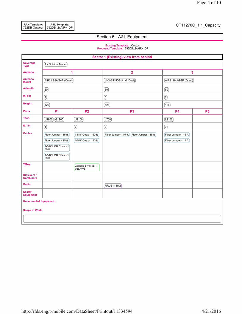
Section 6 - A&L Equipment
RAN Template:792DB Outdoor
A&L Template:792DB_2xAIR+1DP
CT11270C_1.1_Capacity
Existing Template: Custom Proposed Template: 792DB_2xAIR+1DP
Sector 1 (Existing) view from behindCoverage Type A - Outdoor Macro
Antenna 1 2 3
Antenna Model AIR21 B2A/B4P (Quad) LNX-6515DS-A1M (Dual) AIR21 B4A/B2P (Quad)
Azimuth 80 80 80
M. Tilt 2 0 2
Height 125 125 125
Ports P1 P2 P3 P4 P5
Tech. U1900 G1900 U2100 L700 L2100
E. Tilt 4 7 2 7
Cables Fiber Jumper - 15 ft.
Fiber Jumper - 15 ft.
1-5/8" LMU Coax - 150 ft.
1-5/8" LMU Coax - 150 ft.
1-5/8" Coax - 150 ft.
1-5/8" Coax - 150 ft.
Fiber Jumper - 15 ft. Fiber Jumper - 15 ft. Fiber Jumper - 15 ft.
Fiber Jumper - 15 ft.
TMAs Generic Style 1B - Twin AWS
Diplexers / Combiners
Radio RRUS11 B12
Sector Equipment
Unconnected Equipment:
Scope of Work:
Page 5 of 10
4/21/2016http://rfds.eng.t-mobile.com/DataSheet/Printout/11334594

RAN Template:792DB Outdoor
A&L Template:792DB_2xAIR+1DP
CT11270C_1.1_Capacity
Sector 1 (Proposed) view from behindCoverage Type A - Outdoor Macro
Antenna 1 2 3
Antenna Model AIR21 B2A/B4P (Quad) LNX-6515DS-A1M (Dual) KRD901146/1AIR32 B66Aa/B2a (Octa)
Azimuth 80 80 80
M. Tilt 2 0 2
Height 125 125 125
Ports P1 P2 P3 P4 P5 P6 P7
Tech. U1900 G1900 U2100 L700 L2100 L2100 L1900 L1900
E. Tilt 4 7 2 7 7 7 7
Cables Fiber Jumper - 15 ft.
Fiber Jumper - 15 ft.
1-5/8" Coax - 150 ft.
1-5/8" Coax - 150 ft.
Fiber Jumper - 15 ft. Fiber Jumper - 15 ft.
TMAs Generic Style 1B - Twin AWS
Diplexers / Combiners
Radio RRUS11 B12
Sector Equipment
Unconnected Equipment:
Scope of Work:
Page 6 of 10
4/21/2016http://rfds.eng.t-mobile.com/DataSheet/Printout/11334594

RAN Template:792DB Outdoor
A&L Template:792DB_2xAIR+1DP
CT11270C_1.1_Capacity
Sector 2 (Existing) view from behindCoverage Type A - Outdoor Macro
Antenna 1 2 3
Antenna Model AIR21 B2A/B4P (Quad) LNX-6515DS-A1M (Dual) AIR21 B4A/B2P (Quad)
Azimuth 220 220 220
M. Tilt 2 0 2
Height 125 125 125
Ports P1 P2 P3 P4 P5
Tech. U1900 G1900 U2100 L700 L2100
E. Tilt 3 3 2 4
Cables Fiber Jumper - 15 ft.
Fiber Jumper - 15 ft.
1-5/8" LMU Coax - 150 ft.
1-5/8" LMU Coax - 150 ft.
1-5/8" Coax - 150 ft.
1-5/8" Coax - 150 ft.
Fiber Jumper - 15 ft. Fiber Jumper - 15 ft. Fiber Jumper - 15 ft.
Fiber Jumper - 15 ft.
TMAs Generic Style 1B - Twin AWS
Diplexers / Combiners
Radio RRUS11 B12
Sector Equipment
Unconnected Equipment:
Scope of Work:
Page 7 of 10
4/21/2016http://rfds.eng.t-mobile.com/DataSheet/Printout/11334594

RAN Template:792DB Outdoor
A&L Template:792DB_2xAIR+1DP
CT11270C_1.1_Capacity
Sector 2 (Proposed) view from behindCoverage Type A - Outdoor Macro
Antenna 1 2 3
Antenna Model AIR21 B2A/B4P (Quad) LNX-6515DS-A1M (Dual) KRD901146/1AIR32 B66Aa/B2a (Octa)
Azimuth 220 220 220
M. Tilt 2 0 2
Height 125 125 125
Ports P1 P2 P3 P4 P5 P6 P7
Tech. U1900 G1900 U2100 L700 L2100 L2100 L1900 L1900
E. Tilt 3 3 2 4 4 4 4
Cables Fiber Jumper - 15 ft.
Fiber Jumper - 15 ft.
1-5/8" Coax - 150 ft.
1-5/8" Coax - 150 ft.
Fiber Jumper - 15 ft. Fiber Jumper - 15 ft. Fiber Jumper - 15 ft.
Fiber Jumper - 15 ft.
Fiber Jumper - 15 ft.
Fiber Jumper - 15 ft.
TMAs Generic Style 1B - Twin AWS
Diplexers / Combiners
Radio RRUS11 B12
Sector Equipment
Unconnected Equipment:
Scope of Work:
Page 8 of 10
4/21/2016http://rfds.eng.t-mobile.com/DataSheet/Printout/11334594

RAN Template:792DB Outdoor
A&L Template:792DB_2xAIR+1DP
CT11270C_1.1_Capacity
Sector 3 (Existing) view from behindCoverage Type A - Outdoor Macro
Antenna 1 2 3
Antenna Model AIR21 B2A/B4P (Quad) LNX-6515DS-A1M (Dual) AIR21 B4A/B2P (Quad)
Azimuth 340 340 340
M. Tilt 2 0 2
Height 125 125 125
Ports P1 P2 P3 P4 P5
Tech. U1900 G1900 U2100 L700 L2100
E. Tilt 5 5 2 6
Cables Fiber Jumper - 15 ft.
1-5/8" LMU Coax - 150 ft.
1-5/8" LMU Coax - 150 ft.
Fiber Jumper - 15 ft.
1-5/8" Coax - 150 ft.
1-5/8" Coax - 150 ft.
Fiber Jumper - 15 ft. Fiber Jumper - 15 ft. Fiber Jumper - 15 ft.
Fiber Jumper - 15 ft.
TMAs Generic Style 1B - Twin AWS
Diplexers / Combiners
Radio RRUS11 B12
Sector Equipment
Unconnected Equipment:
Scope of Work:
Page 9 of 10
4/21/2016http://rfds.eng.t-mobile.com/DataSheet/Printout/11334594

RAN Template:792DB Outdoor
A&L Template:792DB_2xAIR+1DP
CT11270C_1.1_Capacity
Sector 3 (Proposed) view from behindCoverage Type A - Outdoor Macro
Antenna 1 2 3
Antenna Model AIR21 B2A/B4P (Quad) LNX-6515DS-A1M (Dual) KRD901146/1AIR32 B66Aa/B2a (Octa)
Azimuth 340 340 340
M. Tilt 2 0 2
Height 125 125 125
Ports P1 P2 P3 P4 P5 P6 P7
Tech. U1900 G1900 U2100 L700 L2100 L2100 L1900 L1900
E. Tilt 5 5 2 6 6 6 6
Cables Fiber Jumper - 15 ft.
Fiber Jumper - 15 ft.
1-5/8" Coax - 150 ft.
1-5/8" Coax - 150 ft.
Fiber Jumper - 15 ft. Fiber Jumper - 15 ft. Fiber Jumper - 15 ft.
Fiber Jumper - 15 ft.
Fiber Jumper - 15 ft.
Fiber Jumper - 15 ft.
TMAs Generic Style 1B - Twin AWS
Diplexers / Combiners
Radio RRUS11 B12
Sector Equipment
Unconnected Equipment:
Scope of Work:
Page 10 of 10
4/21/2016http://rfds.eng.t-mobile.com/DataSheet/Printout/11334594

AIR-32 1.4m, data sheet rev A www.ericsson.com © Ericsson AB, 2015
AIR-32 B4A/B2P & B2A/B66Aa Ericsson Antenna Integrated Radio AIR-32
Radio
Single Band (B4a/B2p) Dual Band (B2a/B66Aa)
Band 2 (1850-1910 / 1930-1990 MHz) Passive frequency band Active frequency band
Band 4 (1710-1755 / 2110-2155 MHz) Active frequency band Subset of Band 66A (AWS 1+3)
Band 66A (1710-1780 / 2110-2180 MHz) N/A Active frequency band
PA Output Power 4 x 30W 2 x (4 x 30) W
Downlink EIRP in bore-sight direction for
each active band
4 x 62.5 dBmi 4 x 62.5 dBmi
Instantaneous bandwidth 45 MHz (W, L) B2: 40 MHz (W, L)
B2: 20 MHz (G)
B66A: 70 MHz (W, L)
Capacity (single standard per unit) 6 GSM
6 WCDMA
2 x 20 MHz LTE
6 GSM (B2 only)
6 WCDMA per Active frequency band
2 x 20 MHz LTE per band
Multi-RAT capability WCDMA and LTE on both
PAs
WCDMA and GSM on both PAs (B2 only)
WCDMA and LTE on both PAs (B2 and B4)
GSM and LTE (B2 only)
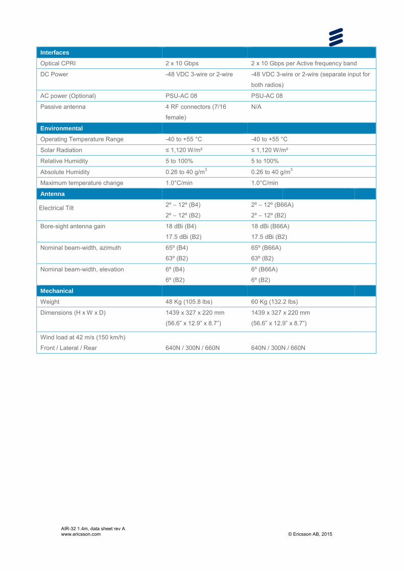
AIR-32 1.4m, data sheet rev A www.ericsson.com © Ericsson AB, 2015
Interfaces
Optical CPRI 2 x 10 Gbps 2 x 10 Gbps per Active frequency band
DC Power -48 VDC 3-wire or 2-wire -48 VDC 3-wire or 2-wire (separate input for
both radios)
AC power (Optional) PSU-AC 08 PSU-AC 08
Passive antenna 4 RF connectors (7/16
female)
N/A
Environmental
Operating Temperature Range -40 to +55 °C -40 to +55 °C
Solar Radiation ≤ 1,120 W/m² ≤ 1,120 W/m²
Relative Humidity 5 to 100% 5 to 100%
Absolute Humidity 0.26 to 40 g/m3 0.26 to 40 g/m3
Maximum temperature change 1.0°C/min 1.0°C/min
Antenna
Electrical Tilt 2º – 12º (B4)
2º – 12º (B2)
2º – 12º (B66A)
2º – 12º (B2)
Bore-sight antenna gain 18 dBi (B4)
17.5 dBi (B2)
18 dBi (B66A)
17.5 dBi (B2)
Nominal beam-width, azimuth 65º (B4)
63º (B2)
65º (B66A)
63º (B2)
Nominal beam-width, elevation 6º (B4)
6º (B2)
6º (B66A)
6º (B2)
Mechanical
Weight 48 Kg (105.8 lbs) 60 Kg (132.2 lbs)
Dimensions (H x W x D) 1439 x 327 x 220 mm
(56.6” x 12.9” x 8.7”)
1439 x 327 x 220 mm
(56.6” x 12.9” x 8.7”)
Wind load at 42 m/s (150 km/h)
Front / Lateral / Rear
640N / 300N / 660N
640N / 300N / 660N

Exhibit F

EBI Consulting environmental | engineering | due diligence
21 B Street . Burlington, MA 01803 . Tel: (781) 273.2500 . Fax: (781) 273.3311
RADIO FREQUENCY EMISSIONS ANALYSIS REPORT EVALUATION OF HUMAN EXPOSURE POTENTIAL
TO NON-IONIZING EMISSIONS
T-Mobile Existing Facility
Site ID: CT11270C
CL&P Bristol 2 Willis Street
Bristol, CT 06010
June 9, 2016
EBI Project Number: 6216002748
Site Compliance Summary
Compliance Status: COMPLIANT
Site total MPE% of FCC general public
allowable limit: 49.45 %

EBI Consulting environmental | engineering | due diligence
21 B Street . Burlington, MA 01803 . Tel: (781) 273.2500 . Fax: (781) 273.3311
June 9, 2016
T-Mobile USA Attn: Jason Overbey, RF Manager 35 Griffin Road South Bloomfield, CT 06002
Emissions Analysis for Site: CT11270C – CL&P Bristol
EBI Consulting was directed to analyze the proposed T-Mobile facility located at 2 Willis Street, Bristol, CT, for the purpose of determining whether the emissions from the Proposed T-Mobile Antenna Installation located on this property are within specified federal limits.
All information used in this report was analyzed as a percentage of current Maximum Permissible Exposure (% MPE) as listed in the FCC OET Bulletin 65 Edition 97-01and ANSI/IEEE Std C95.1. The FCC regulates Maximum Permissible Exposure in units of microwatts per square centimeter (µW/cm2). The number of µW/cm2 calculated at each sample point is called the power density. The exposure limit for power density varies depending upon the frequencies being utilized. Wireless Carriers and Paging Services use different frequency bands each with different exposure limits, therefore it is necessary to report results and limits in terms of percent MPE rather than power density.
All results were compared to the FCC (Federal Communications Commission) radio frequency exposure rules, 47 CFR 1.1307(b)(1) – (b)(3), to determine compliance with the Maximum Permissible Exposure (MPE) limits for General Population/Uncontrolled environments as defined below.
General population/uncontrolled exposure limits apply to situations in which the general public may be exposed or in which persons who are exposed as a consequence of their employment may not be made fully aware of the potential for exposure or cannot exercise control over their exposure. Therefore, members of the general public would always be considered under this category when exposure is not employment related, for example, in the case of a telecommunications tower that exposes persons in a nearby residential area.
Public exposure to radio frequencies is regulated and enforced in units of microwatts per square centimeter (μW/cm2). The general population exposure limit for the 700 MHz Band is approximately 467 μW/cm2, and the general population exposure limit for the 1900 MHz (PCS) and 2100 MHz (AWS) bands is 1000 μW/cm2. Because each carrier will be using different frequency bands, and each frequency band has different exposure limits, it is necessary to report percent of MPE rather than power density.

EBI Consulting environmental | engineering | due diligence
21 B Street . Burlington, MA 01803 . Tel: (781) 273.2500 . Fax: (781) 273.3311
Occupational/controlled exposure limits apply to situations in which persons are exposed as a consequence of their employment and in which those persons who are exposed have been made fully aware of the potential for exposure and can exercise control over their exposure. Occupational/controlled exposure limits also apply where exposure is of a transient nature as a result of incidental passage through a location where exposure levels may be above general population/uncontrolled limits (see below), as long as the exposed person has been made fully aware of the potential for exposure and can exercise control over his or her exposure by leaving the area or by some other appropriate means.
Additional details can be found in FCC OET 65.
CALCULATIONS
Calculations were done for the proposed T-Mobile Wireless antenna facility located at 2 Willis Street, Bristol, CT, using the equipment information listed below. All calculations were performed per the specifications under FCC OET 65. Since T-Mobile is proposing highly focused directional panel antennas, which project most of the emitted energy out toward the horizon, all calculations were performed assuming a lobe representing the maximum gain of the antenna per the antenna manufactures supplied specifications, minus 10 dB, was focused at the base of the tower. For this report the sample point is the top of a 6-foot person standing at the base of the tower.
For all calculations, all equipment was calculated using the following assumptions:
1) 2 GSM channels (PCS Band - 1900 MHz) were considered for each sector of the proposed installation. These Channels have a transmit power of 30 Watts per Channel.
2) 2 UMTS channels (PCS Band - 1900 MHz) were considered for each sector of the proposed installation. These Channels have a transmit power of 30 Watts per Channel.
3) 2 UMTS channels (AWS Band – 2100 MHz) were considered for each sector of the proposed installation. These Channels have a transmit power of 30 Watts per Channel.
4) 2 LTE channels (PCS Band - 1900 MHz) were considered for each sector of the proposed
installation. These Channels have a transmit power of 60 Watts per Channel. 5) 2 LTE channels (AWS Band – 2100 MHz) were considered for each sector of the proposed
installation. These Channels have a transmit power of 60 Watts per Channel. 6) 1 LTE channel (700 MHz Band) was considered for each sector of the proposed installation.
This channel has a transmit power of 30 Watts.

EBI Consulting environmental | engineering | due diligence
21 B Street . Burlington, MA 01803 . Tel: (781) 273.2500 . Fax: (781) 273.3311
7) All radios at the proposed installation were considered to be running at full power and were uncombined in their RF transmissions paths per carrier prescribed configuration. Per FCC OET Bulletin No. 65 - Edition 97-01 recommendations to achieve the maximum anticipated value at each sample point, all power levels emitting from the proposed antenna installation are increased by a factor of 2.56 to account for possible in-phase reflections from the surrounding environment. This is rarely the case, and if so, is never continuous.
8) For the following calculations the sample point was the top of a six-foot person standing at the base of the tower. The maximum gain of the antenna per the antenna manufactures supplied specifications minus 10 dB was used in this direction. This value is a very conservative estimate as gain reductions for these particular antennas are typically much higher in this direction.
9) The antennas used in this modeling are the Ericsson AIR32 B66Aa/B2A & Ericsson AIR21 B2A/B4P for 1900 MHz (PCS) and 2100 MHz (AWS) channels and the Commscope LNX-6515DS-VTM for 700 MHz channels. This is based on feedback from the carrier with regards to anticipated antenna selection. The Ericsson AIR32 B66Aa/B2A & Ericsson AIR21 B2A/B4P have a maximum gain of 15.9 dBd at their main lobe at 1900 MHz and 2100 MHz. The Commscope LNX-6515DS-VTM has a maximum gain of 14.6 dBd at its main lobe at 700 MHz. The maximum gain of the antenna per the antenna manufactures supplied specifications, minus 10 dB, was used for all calculations. This value is a very conservative estimate as gain reductions for these particular antennas are typically much higher in this direction.
10) The antenna mounting height centerline of the proposed antennas is 125 feet above ground
level (AGL). 11) Emissions values for additional carriers were taken from the Connecticut Siting Council
active database. Values in this database are provided by the individual carriers themselves.
All calculations were done with respect to uncontrolled / general public threshold limits.
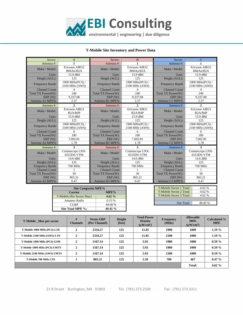
EBI Consulting environmental | engineering | due diligence
21 B Street . Burlington, MA 01803 . Tel: (781) 273.2500 . Fax: (781) 273.3311
T-Mobile Site Inventory and Power Data
Sector: A Sector: B Sector: C Antenna #: 1 Antenna #: 1 Antenna #: 1
Make / Model: Ericsson AIR32 B66Aa/B2A Make / Model: Ericsson AIR32
B66Aa/B2A Make / Model: Ericsson AIR32 B66Aa/B2A
Gain: 15.9 dBd Gain: 15.9 dBd Gain: 15.9 dBd Height (AGL): 125 Height (AGL): 125 Height (AGL): 125
Frequency Bands 1900 MHz(PCS) / 2100 MHz (AWS) Frequency Bands 1900 MHz(PCS) /
2100 MHz (AWS) Frequency Bands 1900 MHz(PCS) / 2100 MHz (AWS)
Channel Count 4 Channel Count 4 Channel Count 4 Total TX Power(W): 240 Total TX Power(W): 240 Total TX Power(W): 240
ERP (W): 9,337.08 ERP (W): 9,337.08 ERP (W): 9,337.08 Antenna A1 MPE% 2.37 Antenna B1 MPE% 2.37 Antenna C1 MPE% 2.37
Antenna #: 2 Antenna #: 2 Antenna #: 2
Make / Model: Ericsson AIR21 B2A/B4P Make / Model: Ericsson AIR21
B2A/B4P Make / Model: Ericsson AIR21 B2A/B4P
Gain: 15.9 dBd Gain: 15.9 dBd Gain: 15.9 dBd Height (AGL): 125 Height (AGL): 125 Height (AGL): 125
Frequency Bands 1900 MHz(PCS) / 2100 MHz (AWS) Frequency Bands 1900 MHz(PCS) /
2100 MHz (AWS) Frequency Bands 1900 MHz(PCS) / 2100 MHz (AWS)
Channel Count 6 Channel Count 6 Channel Count 6 Total TX Power(W): 180 Total TX Power(W): 180 Total TX Power(W): 180
ERP (W): 7,002.81 ERP (W): 7,002.81 ERP (W): 7,002.81 Antenna A2 MPE% 1.78 Antenna B2 MPE% 1.78 Antenna C2 MPE% 1.78
Antenna #: 3 Antenna #: 3 Antenna #: 3
Make / Model: Commscope LNX-6515DS-VTM Make / Model: Commscope LNX-
6515DS-VTM Make / Model: Commscope LNX-6515DS-VTM
Gain: 14.6 dBd Gain: 14.6 dBd Gain: 14.6 dBd Height (AGL): 125 Height (AGL): 125 Height (AGL): 125
Frequency Bands 700 MHz Frequency Bands 700 MHz Frequency Bands 700 MHz Channel Count 1 Channel Count 1 Channel Count 1
Total TX Power(W): 30 Total TX Power(W): 30 Total TX Power(W): 30 ERP (W): 865.21 ERP (W): 865.21 ERP (W): 865.21
Antenna A3 MPE% 0.47 Antenna B3 MPE% 0.47 Antenna C3 MPE% 0.47
Site Composite MPE% Carrier MPE%
T-Mobile (Per Sector Max) 4.62 % Amateur Radio 0.15 %
CL&P 44.68 % Site Total MPE %: 49.45 %
T-Mobile Sector 1 Total: 4.62 % T-Mobile Sector 2 Total: 4.62 % T-Mobile Sector 3 Total: 4.62 %
Site Total: 49.45 %
T-Mobile _Max per sector # Channels
Watts ERP (Per Channel)
Height (feet)
Total Power Density
(µW/cm2)
Frequency (MHz)
Allowable MPE
(µW/cm2)
Calculated % MPE
T-Mobile 1900 MHz (PCS) LTE 2 2334.27 125 11.85 1900 1000 1.19 %
T-Mobile 2100 MHz (AWS) LTE 2 2334.27 125 11.85 2100 1000 1.19 %
T-Mobile 1900 MHz (PCS) GSM 2 1167.14 125 5.93 1900 1000 0.59 %
T-Mobile 1900 MHz (PCS) UMTS 2 1167.14 125 5.93 1900 1000 0.59 %
T-Mobile 2100 MHz (AWS) UMTS 2 1167.14 125 5.93 2100 1000 0.59 %
T-Mobile 700 MHz LTE 1 865.21 125 2.20 700 467 0.47 %
Total: 4.62 %

EBI Consulting environmental | engineering | due diligence
21 B Street . Burlington, MA 01803 . Tel: (781) 273.2500 . Fax: (781) 273.3311
Summary
All calculations performed for this analysis yielded results that were within the allowable limits for general public exposure to RF Emissions.
The anticipated maximum composite contributions from the T-Mobile facility as well as the site composite emissions value with regards to compliance with FCC’s allowable limits for general public exposure to RF Emissions are shown here:
T-Mobile Sector Power Density Value (%) Sector 1: 4.62 % Sector 2: 4.62 % Sector 3: 4.62 %
T-Mobile Per Sector Maximum:
4.62 %
Site Total: 49.45 %
Site Compliance Status: COMPLIANT
The anticipated composite MPE value for this site assuming all carriers present is 49.45% of the allowable FCC established general public limit sampled at the ground level. This is based upon values listed in the Connecticut Siting Council database for existing carrier emissions.
FCC guidelines state that if a site is found to be out of compliance (over allowable thresholds), that carriers over a 5% contribution to the composite value will require measures to bring the site into compliance. For this facility, the composite values calculated were well within the allowable 100% threshold standard per the federal government.