exhibit g project management plan, implementation schedule ... · exhibit g - project management...
TRANSCRIPT

Exhibit G - Project Management Plan, Implementation Schedule, and Cutover Plan 800 MHz Emergency Communications Systems For Sarasota and Manatee Counties
RFP 142842TM
G-1
Exhibit G – Project Management Plan, Implementation Schedule, and Cutover Plan

Exhibit G - Project Management Plan, Implementation Schedule, and Cutover Plan 800 MHz Emergency Communications Systems For Sarasota and Manatee Counties
RFP 142842TM
G-2
Project Management Plan, Implementation Schedule and Cutover Plan
Introduction
Overview
This document is the preliminary Project Management Plan for a 700/800 MHz P25 Public Safety Radio Network for the Counties. Within seven days of issuance of purchase orders, the Counties and Contractor will meet and agree upon the Project Management Plan. The Project Management Plan will be subject to change based on mutual agreement based on the site development and other implementation of the System.
The Project Management Plan describes how Contractor manages the successful implementation of the VESTA Radio System for the Counties from contract award to system acceptance and transition to Customer Care (Warranty and Maintenance Support). This plan describes how the Contractor’s standard management processes will be applied to ensure that necessary quality controls will be used at an appropriate level for efficient and effective project implementation. These management processes are a culmination of years of experience successfully cutting over mission critical systems ensuring they stay on-time, on-budget, and on-quality.
Project Management Philosophy
Contractor’s goal for every project is to deliver a high-quality system on-time and within budget, that exceeds the customer’s requirements. This requires outstanding execution at every stage of the project:
Outstanding Team – Contractor assembles a core team of highly experienced professionals. Kevin Mumma, The Contractor’s Project Manager in Bradenton, FL, will own the overall delivery of the solution with total responsibility and decision making for the Counties’ project.
Outstanding Communication – Identifying and exercising a rigorous and focused communication plan among team members will keep everyone focused on the objectives, mitigate misunderstandings, and minimize problems.
Outstanding Quality – Quality checks are built into Contractor’s projects to ensure quality of work and materials.
Services
Contractor will perform the following services in order to achieve a successful implementation:
Project Management
System Design
Installation of Site Equipment
System Integration, Commissioning, and Optimization
Civil Construction and Site Development
Radio Coverage Testing
System Acceptance Testing
Training
Warranty for One Year After Final System Acceptance
Decommissioning of Existing Equipment

Exhibit G - Project Management Plan, Implementation Schedule, and Cutover Plan 800 MHz Emergency Communications Systems For Sarasota and Manatee Counties
RFP 142842TM
G-3
Equipment
Contractor will provide the Counties with a completely integrated, turnkey System consisting of the following major communications system components:
Dispatch Console System
Zetron Acom IP system with 42 console positions distributed as follows:
Sarasota
o 15 console positions at EOC
o 4 console positions at North Port (which may be relocated to the Sarasota EOC)
Manatee
o 20 console positions at Manatee PSC
o 3 console positions at Bradenton
10 Control Station Radios at the legacy Manatee Backup EOC
VESTA Radio, P25-compliant, Trunked Radio Network with:
800 MHz Simulcast Cell, 9 sites, 17 channels for Sarasota
800 MHz Simulcast Cell, 9 sites, 16 channels for Manatee
One 4-channel multicast site for aviation
Shared VESTA Radio Infrastructure
Geo-Redundant Core
Geo-Redundant Simulcast Site Controller
Alarm and Diagnostic subsystem
Network Management subsystem
Future ISSI connectivity
Interoperability
Sarasota
Two (2) new Analog 800 MHz Mutual Aid channels (8CALL90 & 8TAC92) at six (6) Sarasota Sites
FIN (Florida Interoperability Network)
Legacy Interops
Legacy SmartZone System during the Cutover Period
Manatee
Reuse of the legacy Manatee Analog 800 MHZ Mutual Aid Channels
FIN (Florida Interoperability Network)
Legacy Interops
Legacy Harris EDACS System during the Cutover Period

Exhibit G - Project Management Plan, Implementation Schedule, and Cutover Plan 800 MHz Emergency Communications Systems For Sarasota and Manatee Counties
RFP 142842TM
G-4
Remote Monitoring of the VESTA Radio System
Twenty four hours a day, seven days a week
Logging Recorder
EXACOM logging recorder solution for each County
Microwave
Aviat Digital Microwave and Backhaul IP Network
Available Options
Subscriber Units
OTAP
KMF / OTAR
Project Team
Organization
Contractor’s project team includes experienced LMR professionals and subject matter experts for the design and support of the Counties 800 MHz P25 Public Safety Radio Network. The project team includes executive management support that ensures the availability of all of the resources to meet the Counties' needs. The project team includes multiple disciplines and is structured as shown in Figure 1. Key team members have been assigned. Other roles will be assigned at the execution of the Agreement.

Exhibit G - Project Management Plan, Implementation Schedule, and Cutover Plan 800 MHz Emergency Communications Systems For Sarasota and Manatee Counties
RFP 142842TM
G-5
At the beginning of project execution, one of the first actions of the Project Manager is to mobilize the project team. A matrix type organization as illustrated below represents the project team established for the Counties’ project.
Figure 1 Project Team

Exhibit G - Project Management Plan, Implementation Schedule, and Cutover Plan 800 MHz Emergency Communications Systems For Sarasota and Manatee Counties
RFP 142842TM
G-6
Roles and Responsibilities
Project Manager
The Contractor’s On-Site Project Manager, Kevin Mumma, living in Bradenton, FL, is responsible for the delivery of the project on-time, within budget and to contract specifications, the Project Manager will work on-site during the entire deployment until the Counties’ Final System Acceptance. Contractor’s Project Manager plans, coordinates, and oversees all aspects of the project implementation and reports on its progress. The Project Manager will be the primary point of contact for the Counties following contract award. The Project Manager will reside in the Counties’ area for the entire duration of the project and is readily available to the Counties’ Project Administrators with a local telephone number for contact.
The Project Manager’s specific duties include:
Providing all necessary resources in order to guarantee an effective delivery of the project
Meeting the project goals with regard to quality, cost and time
Creating and managing the project schedule
Managing all staff and subcontractors
Coordinating and scheduling of the civil construction and site development
Planning, monitoring, and controlling the project according to defined standards
Creating and maintaining the Project Management Plan
Reporting project progress and status
Providing project deliverables to the Counties
Coordinating regular project meetings, design reviews, and other meetings as needed
Identifying and reconciling issues proactively
Providing an escalation path
Managing the Change Control Process
Technical Solutions Engineer
Technical Solution Engineers (TSE) deal with all technical aspects of the project during the design phase. The Lead TSE, Peter Ungar, ensures suitability and compliance of the solution with the Counties’ functional, operational, and contractual requirements by:
Providing the technical specifications of the solution
Defining the solution architecture for the solution in collaboration with sub-system suppliers
Defining the scope of supply and providing the equipment list for the project
Providing the configuration documentation needed for the solution
Providing the Acceptance Test Protocols for the solution
Participating in the Factory Acceptance Test and System Acceptance Test

Exhibit G - Project Management Plan, Implementation Schedule, and Cutover Plan 800 MHz Emergency Communications Systems For Sarasota and Manatee Counties
RFP 142842TM
G-7
Radio Network Engineer
Radio Network Engineers (RNE) deal with all RF (Radio Frequency) related technical aspects of the project. The Radio Network Engineer, Doug Petrie, is responsible for:
Managing the design of the radio network to ensure compliance with the Counties’ functional and operational requirements
Frequency planning
Intermodulation detection and resolution
Managing the validation of radio coverage
Deployment Manager
Implementation Management covers all the activities for the implementation of the network through the System Acceptance phase. The Deployment Manager, Greg Tanner, is part of the core project team and is responsible for successfully implementing the complete solution.
The Deployment Manager responsibilities include:
Managing the integration, staging, and field testing of the solution including interfaces with external equipment
Organizing the deployment logistics
Performing radio site surveys and validation
Defining the deployment strategy and consolidating supplier’s deployment solutions
Determining local administrative constraints (documentation, working safety rules, technical standards, etc.)
Managing subcontractors
The Deployment Manager manages the Implementation Team, which consists of Site Development Services and System Installation and Integration Services:
Site Development Services
This functional team has responsibility for site acquisition and preparation. The group includes:
Site Acquisition Specialists
Regulatory and Compliance Specialists
Construction Managers
Infrastructure Engineers

Exhibit G - Project Management Plan, Implementation Schedule, and Cutover Plan 800 MHz Emergency Communications Systems For Sarasota and Manatee Counties
RFP 142842TM
G-8
System Installation and Integration Services
The second functional team has responsibility for the installation and integration of the System, from completion of design activities through factory staging and field commissioning of the System, testing, and cutover. The group includes:
Field Engineers
RF Engineers
Staging Managers
Fabrication Technicians
Training Manager
Effective trainers are vital to providing dynamic, successful training programs and enable their trainees to learn and internalize the content being taught. Contractor’s trainers will tailor the classroom experience to meet the Counties’ specific training needs. The main responsibilities of the Training Manager, Joe Tomlinson, are:
Identifying training and development needs through regular consultation with the Counties
Designing and developing training based on the Counties’ needs
Working in a team to produce programs that are satisfactory to all relevant parties including:
o Administrators
o Operators
o Technicians
o Managers
Managing the delivery of the training programs including those supplied by our subcontractors
Monitoring and reviewing the progress of trainees through the use of questionnaires and discussions with the Counties’ managers
Subcontractors
Contractor selects subcontractors based on their qualifications and their ability to perform specific functions for the contract. They have demonstrated an ability to perform high-level services and work within the framework of the project team.
Although Contractor offers a wide range of operations, maintenance, and engineering services, Contractor does subcontract certain tasks that are intermittent, or require highly specialized skills and equipment. Contractor employs qualified subcontractors for their technical knowledge, specialized skills, and reliability, serving as a vital resource in the success of a project.

Exhibit G - Project Management Plan, Implementation Schedule, and Cutover Plan 800 MHz Emergency Communications Systems For Sarasota and Manatee Counties
RFP 142842TM
G-9
Contractor’s key subcontractors for the Counties’ Project include:
Zetron – Dispatch console systems
Aviat – Microwave systems
Black and Veatch – Site development
Alpha and Omega – Microwave installations
Williams Communications – Installation and local support services
Care Manager
The Care Manager, Linda McSweeney, is responsible for overall customer support, including training, upgrades and repair processes. Before Final System Acceptance, the Care Manager plans and organizes the appropriate training for the Counties and Local Service Partner(s), and creates the Care Plan in collaboration with the Counties. After Final System Acceptance, the Care Manager implements the Care Plan, and takes over the Project Management responsibilities for the Warranty and Maintenance period.
The Care Manager’s specific duties include:
Providing all necessary resources in order to guarantee effective support for the Counties
Creating and maintaining the Care Services Plan
Defining spare parts list, storage, and logistics
Establishing third-party care agreements, if required
Setting up the appropriate processes to support the Counties
Setting up ongoing progress meetings with the Counties' point of contact
Proactively identifying and reconciling support issues
Procurement Manager and Supply Manager
Project Procurement and Supply Management consists of all project equipment, material, partner, and subcontractor-related procurement activities and the required actions according to technical specifications, purchasing principles, philosophies, and procurement schedules, within approved cost estimates.
Bryant Underwood’s and Glenn Snodderly’s procurement activities include partner and subcontractor inquiries, negotiations, contract agreements, project logistics, and local warehousing management.
All major subsystems are subcontracted using industry standard, Master Agreement/Statement of Work subcontracting vehicles. The entire tender and subcontracting process comprehends all customer-required flowdowns and supplier performance obligations. The subcontract structure and methods used mirror those used for aerospace and defense. Suppliers of major subsystems or services are all vetted for finance, corporate structure, litigation, safety, public filings, and technical performance prior to an invitation to the tendering process. System-level quality is evaluated based on system availability and MTBF calculations as assessed by customer requirements and Contractor engineering. This closed-loop process control with tightly integrated contracting tools works to assure outstanding performance and superior risk mitigation.

Exhibit G - Project Management Plan, Implementation Schedule, and Cutover Plan 800 MHz Emergency Communications Systems For Sarasota and Manatee Counties
RFP 142842TM
G-10
Project Management Services
The following subsections describe the primary areas of focus and tasks performed by the project management team, which is lead by Contractor’s on-site Project Manager.
The Project Management tasks are based on Contractor’s standard project management process and are in alignment with the practices and philosophy of the Project Management Institute (PMI). This process is a set of common and standard rules used by Contractor and deals with the fulfillment of contracts based on the Project Management Plan (PMP).
The PMP is a key project document deliverable as it customizes the application of the general principles of Contractor’s project management process to the Counties' solution technology, project scope, contract size, and contract specifics.
Contractor’s project team is supported by the Project Management Office (PMO) and provides head office support to ensure quality and process adherence.
Coordination and Progress Management
Project coordination is the responsibility of the Project Manager. The Project Manager focuses on managing and controlling the delivery of project activities according to the contractual agreements, the Project Plan, and the Scope of Work. This is done through all project phases to ensure quality, cost, and time-efficient project execution.
Certain project coordination activities are essential for successful project execution. These coordination activities include:
Updating the preliminary Project Management Plan for the Counties' approval
Continuous updating of the Project Management Plan during project execution
Establishing the project management team
Staffing the project organization
Defining and executing the Project Communication Plan
Reporting project progress and status
Performing Project Scope and Configuration Management from initial scope definition to agreed scope changes
The Project Manager, Project Financial Controller, and PMO Manager meet on a regular basis to review progress and execution of the Project Plan to ensure that the project is implemented according to contractual requirements, plans, and schedules, within projected budgets and to operational objectives.

Exhibit G - Project Management Plan, Implementation Schedule, and Cutover Plan 800 MHz Emergency Communications Systems For Sarasota and Manatee Counties
RFP 142842TM
G-11
Implementation Process and Quality Assurance Management
Overview
Contractor’s Project Manager follows the Implementation Process and Quality Assurance Gates illustrated in Figure 2. This process demonstrates the methodical and strategic approach to implementing systems.
The Implementation Process and Quality Assurance process ensures that the project is delivered on-time, on-budget, and on-quality. Quality Gate reviews fundamentally reduce risk to a project and are linked to important decisions such as finalizing the system architecture design or starting the system installation.
Mobilization
QG 05
Preliminary
DesignQG 06
Final
DesignQG 07
System
ProductionQG 08
System
Acceptance QG 10
Care
QG 11
Planning Design Production Installation Integration & Validation Maintenance
Field Installation &
System CommissioningQG 09
RequirementReview
PDRReview
FDRReview
FactoryAcceptance
SiteAcceptance
Cutover Review
System Acceptance
Figure 2 Implementation Process and Quality Assurance Gate Process
Quality Gate reviews are held in order to assess the current and future state of the project. Deliverables include the appropriate project documentation which are presented at each of the corresponding Quality Gate reviews.
Significant senior management oversight is employed during Quality Gate Reviews in order to ensure a comprehensive assessment of the project status. The Project Manager is responsible for ensuring that the Gates are planned and executed. The ’Contractor's Project Quality Manager (PQM) reviews the status of each Quality Gate, the impact of issues, and suggests recommendations to Project Team members. The PQM provides notice of Gate decisions and rationalization to the project team with updates to the Project Management Plan and Quality Gate repository. The PQM issues a Pass notice when the project is authorized to proceed to the next phase.
The following sections provide a general description of each Quality Gate.
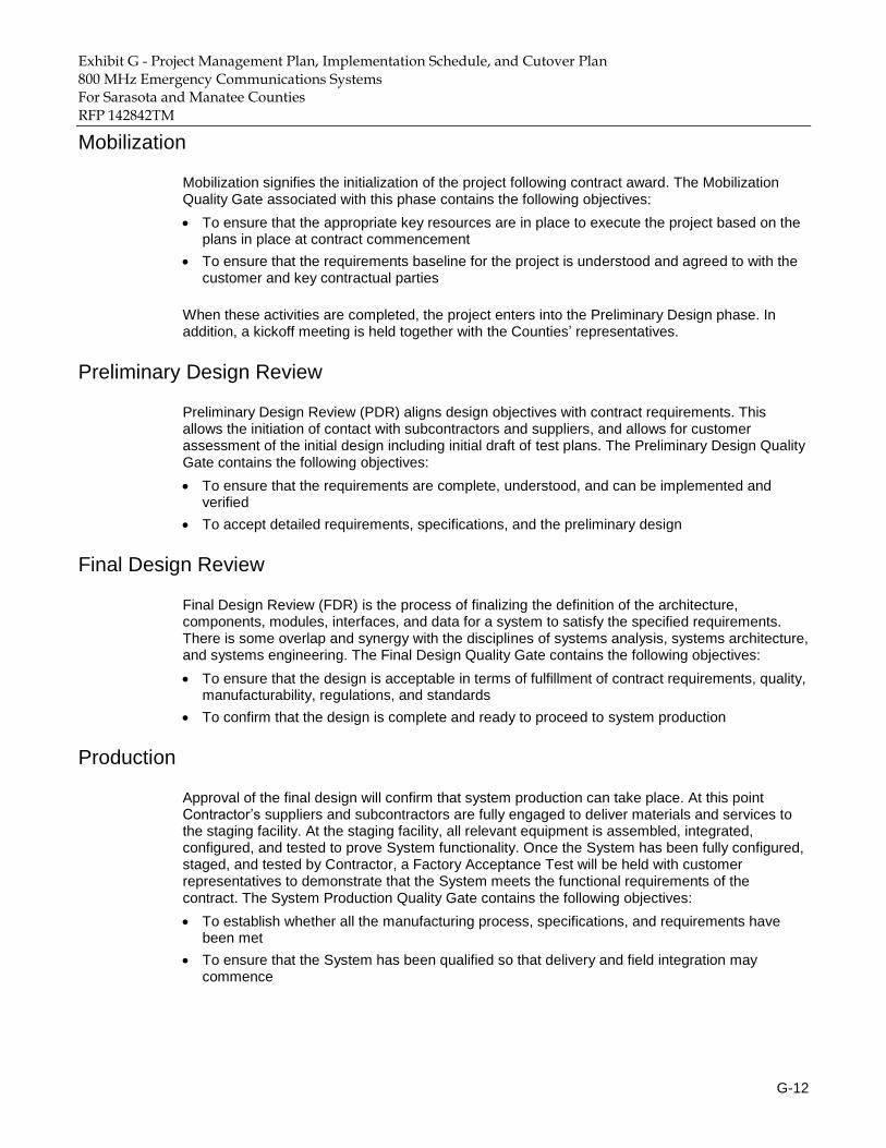
Exhibit G - Project Management Plan, Implementation Schedule, and Cutover Plan 800 MHz Emergency Communications Systems For Sarasota and Manatee Counties
RFP 142842TM
G-12
Mobilization
Mobilization signifies the initialization of the project following contract award. The Mobilization Quality Gate associated with this phase contains the following objectives:
To ensure that the appropriate key resources are in place to execute the project based on the plans in place at contract commencement
To ensure that the requirements baseline for the project is understood and agreed to with the customer and key contractual parties
When these activities are completed, the project enters into the Preliminary Design phase. In addition, a kickoff meeting is held together with the Counties’ representatives.
Preliminary Design Review
Preliminary Design Review (PDR) aligns design objectives with contract requirements. This allows the initiation of contact with subcontractors and suppliers, and allows for customer assessment of the initial design including initial draft of test plans. The Preliminary Design Quality Gate contains the following objectives:
To ensure that the requirements are complete, understood, and can be implemented and verified
To accept detailed requirements, specifications, and the preliminary design
Final Design Review
Final Design Review (FDR) is the process of finalizing the definition of the architecture, components, modules, interfaces, and data for a system to satisfy the specified requirements. There is some overlap and synergy with the disciplines of systems analysis, systems architecture, and systems engineering. The Final Design Quality Gate contains the following objectives:
To ensure that the design is acceptable in terms of fulfillment of contract requirements, quality, manufacturability, regulations, and standards
To confirm that the design is complete and ready to proceed to system production
Production
Approval of the final design will confirm that system production can take place. At this point Contractor’s suppliers and subcontractors are fully engaged to deliver materials and services to the staging facility. At the staging facility, all relevant equipment is assembled, integrated, configured, and tested to prove System functionality. Once the System has been fully configured, staged, and tested by Contractor, a Factory Acceptance Test will be held with customer representatives to demonstrate that the System meets the functional requirements of the contract. The System Production Quality Gate contains the following objectives:
To establish whether all the manufacturing process, specifications, and requirements have been met
To ensure that the System has been qualified so that delivery and field integration may commence

Exhibit G - Project Management Plan, Implementation Schedule, and Cutover Plan 800 MHz Emergency Communications Systems For Sarasota and Manatee Counties
RFP 142842TM
G-13
Installation and Commissioning
Following successful completion of the Factory Acceptance Test, the System is delivered, installed, and commissioned.
Prior to the installation commencing, Contractor will perform a Site Certification to verify that all sites are fully ready and approved to commence the installation of the System.
Following the installation of the System, Site Acceptances will be performed to ensure that the equipment has been installed in accordance with this Agreement and to the satisfaction of the Counties.
System Acceptance
System Acceptance ensures that all conditions for the transition of systems from delivery into service and support, in accordance with the contractual requirements are met. The System Acceptance Quality Gate associated with this phase contains the following objectives:
To ensure that the System operates in accordance with the contract requirements
To ensure that the Counties can cutover to the new VESTA Radio system
To validate readiness for Care Services support
Care (Warranty and Maintenance)
The Care Quality Gate contains the following objective:
To ensure that all required maintenance and support services are identified and under control of the assigned Care Manager
Communications Management
This section sets the Project Reporting framework and serves as a guide for communication and reporting throughout the project. It identifies and defines the roles of persons involved in this project. It also includes a Reporting matrix which maps the reporting requirements of this project.
Communications between the Counties and Contractor includes on-site discussions, email, telephone, and teleconference methods as appropriate for the following types of communications:
Documentation sharing including use of online applications
Project meetings and reviews as described in the Communications Matrix
Escalation Process
Change Control Process

Exhibit G - Project Management Plan, Implementation Schedule, and Cutover Plan 800 MHz Emergency Communications Systems For Sarasota and Manatee Counties
RFP 142842TM
G-14
Shared Documentation
Shared documentation is stored online using a portal for partners, customers, and associates to online services provided by Contractor. Registered users have easy access to Contractor’s product information, technical documentation, software downloads, and collaboration tools. The Contractor’s Online portal can be accessed from the internet.
Contractor provides a Team Service area for the Counties, which is a separate project collaboration area where Contractor’s and the Counties' teams can share confidential or specific information with customers or partners.
Project Meetings and Reviews
Contractor will hold regular reviews with the Counties to present information on the current status of the project, designs, activities, and deliverables. The goal of these reviews is to ensure good communication between all parties on the status of the project and to reach agreement on technical matters. The following reviews are held at times and locations mutually agreeable to Contractor and the Counties:
Kickoff meeting
Regular Project Meetings, including:
o Technical and configuration discussions
o Preliminary Design Review
o Final Design Review
o Testing and Validation
o Cutover and Transition
o Care Planning
Milestone Review Meetings
Executive Reviews
Communications Matrix
At the start of the project the Contractor’s Project Manager will hold a Kickoff Meeting with the Counties in order to introduce the project team, review the project scope, requirements, timelines, task owners, communication procedures as well as the risks and mitigations management. Contractor and the Counties’ team members will hold a variety of meetings throughout the design and implementation of the project.
Table 1 summarizes the types of meetings that will occur along with the meeting’s objective, medium, frequency, intended audience, owner, and deliverables. This proposed Communications Matrix will be presented during the Kickoff meeting and adapted to meet stakeholder needs.

Exhibit G - Project Management Plan, Implementation Schedule, and Cutover Plan 800 MHz Emergency Communications Systems For Sarasota and Manatee Counties
RFP 142842TM
G-15
Table 1 Proposed Communications Matrix
Type Objective Medium Freq. Audience Owner Deliverables
Kickoff Meeting
Introduce project team review project scope,
timelines, task owners, communication procedures,
preliminary risk identification
Face to Face
Once
County project teams, Contractor
project team, Stakeholders
PM Kickoff slides
Meeting Minutes
Customer Project
Meetings
Review status of the project with Sarasota-Manatee
Counties
Conference Call or Face to
Face
Bi-Weekly
County PAs, Contractor PM,
Technical resources as needed.
PM
Status/Schedule Progress Report
Issues Risk &
Mitigations Action Item
update Meeting Minutes
Internal Project Team
Meetings
Review status of the project with the team (similar to
above)
Conference Call or Face to
Face
Weekly Contractor Project
Team PM
(similar to above)
Milestone Reviews
Discuss milestone deliverables with Sarasota-
Manatee Counties.
Conference Call or Face to
Face
Once each
County PAs, Contractor PM,
Milestone owner, Technical
Resources as needed.
Milestone owner
Agenda Deliverable
Meeting Minutes
Internal Project Review
Report the status of the project including activities, progress, costs and issues
Conference Call or Face to
Face
Monthly
Executive Sponsor, PMO,
Contractor PM, Technical
Resources as needed
PM Status Report
Internal Quality Gate
Reviews
Assess the current and future state of the project.
Conference Call
Quality Gate
Contractor PM, PQM, PMO,
Project Team PM QG Deliverables
Executive Review
Discuss project status including health of the
project, critical path issues and any project non-
conformance
Conference Call or Face to
Face
As needed
County PAs, Executive Sponsor,
Contractor PM PM
Agenda Status update
Meeting Minutes

Exhibit G - Project Management Plan, Implementation Schedule, and Cutover Plan 800 MHz Emergency Communications Systems For Sarasota and Manatee Counties
RFP 142842TM
G-16
Meeting Minutes
The following figure is an example of the Counties' Project Status Update Minutes that will be sent out by the Project Manager within 48 hours of Customer Project Meetings.
Figure 3 Meeting Minutes Format

Exhibit G - Project Management Plan, Implementation Schedule, and Cutover Plan 800 MHz Emergency Communications Systems For Sarasota and Manatee Counties
RFP 142842TM
G-17
Action Items Register
Table 2 is an example of the Action Items Register that will be sent out by the Project Manager together with the Counties' Project Status Update Minutes.
Table 2 Action Items Register
ID Action Owner Date
Assigned Date Due
Current Estimate
1 Coordinate Project Kickoff Meeting Airbus DS
Communications PM
2
3
Escalation Process
An Escalation Process will be put in place in order to address project issues including significant schedule slips exceeding 10 working days, or technical, financial, or other contractual matters that the project core team is unable to address. This is presented in Table 3.
Table 3 Escalation Process
# Description Initiator
(Airbus DS Communications)
Initiator (County)
1
Unresolved risk and/or issue after reasonable efforts at cooperation during the project meetings. Project Manager communicates activation of escalation to counterpart and next-level management at Contractor and the Counties’ Initiator provides written description of the problem and impact on project.
Project Manager
Project
Manager
2
Meeting or call coordinated by the initiator must occur within 3 working days of communication of escalation information. Resolution, corrective action, and mutually agreed-upon schedules are identified during the discussion. If the parties are unable to reach an agreement or if the corrective action is not implemented within the agreed-upon timeframe, the matter is escalated.
Vice President of
Programs and
Customer Care
TBD by
County
3
Meeting or conference call coordinated by the initiator must occur within 3 working days of communication of escalation information. Resolution, corrective action, and mutually agreed-upon schedules are identified during the discussion.
Chief Operating
Officer
TBD By
County

Exhibit G - Project Management Plan, Implementation Schedule, and Cutover Plan 800 MHz Emergency Communications Systems For Sarasota and Manatee Counties
RFP 142842TM
G-18
Change Control Management
Project scope is regularly monitored and controlled by the Project Manager and the project team. Scope change will be managed through the Change Control Process described below under the responsibility of the Project Management Office. Major changes will be managed through contract amendments signed by the Counties and Contractor pursuant to the process set forth in Exhibit B.
Process Overview
A Change Control Process (CCP) will be used to track changes to the project with associated governance. The CCP will be used to control changes to configuration items (including contract, schedule, requirements, technical, etc.) to ensure that only authorized changes are applied. It involves receiving requests for change, analyzing them for impact/feasibility, approving them before implementation, and tracking them through completion.
Elements of a Change Control Process include:
Project Change Notice Form – A template form is provided in Figure 4.
Change Control Board (CCB) – Comprised of department representatives from the Project Management Office (PMO), Engineering, Implementation, and Care.
Authorized Signatories –If the change does not involve the project schedule, project cost, or degrade technical performance then the change request need only be reviewed by Contractor’s Change Control Board members. Signature authority resides with the Contractor’s Project Manager.
A Change Request can be initiated by any member of the project team by completing a Change Notice Form and submitting it to a Project Manager.
Process Steps
The following steps summarize the Change Control Process:
1. A Project Change Notice Form is completed and submitted to the Project Manager.
2. The Project Manager assigns a change number and distributes the Project Change Notice Form to members of the project team and adds a review to the agenda of the next Change Control Board meeting.
3. The Change Control Board meeting is held and the request, the reason for the request, and the impact on the project are discussed. If necessary, changes are made to the Project Change Notice Form.
4. The members of the Change Control Board indicate their approval or disapproval of the change request.
5. The authorized signatory signs or rejects the change request on the Project Change Notice Form. If a change request is rejected, then a written rebuttal must be provided by the responsible authorized signatory.
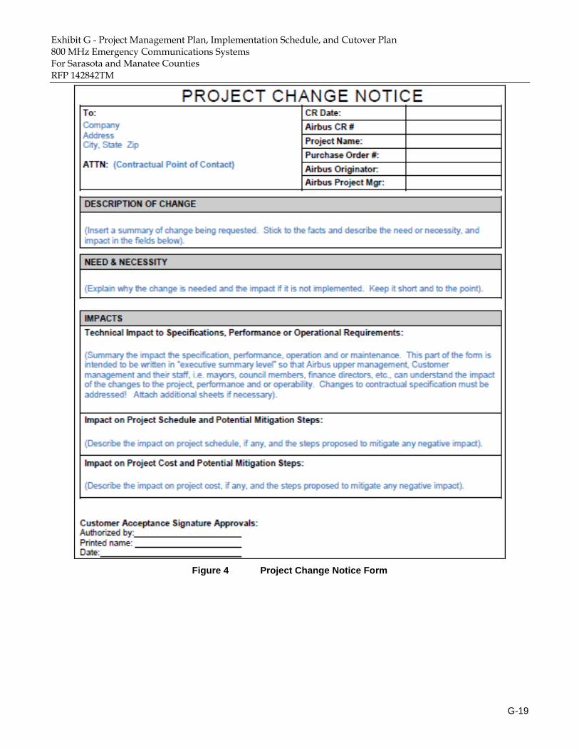
Exhibit G - Project Management Plan, Implementation Schedule, and Cutover Plan 800 MHz Emergency Communications Systems For Sarasota and Manatee Counties
RFP 142842TM
G-19
Figure 4 Project Change Notice Form

Exhibit G - Project Management Plan, Implementation Schedule, and Cutover Plan 800 MHz Emergency Communications Systems For Sarasota and Manatee Counties
RFP 142842TM
G-20
Risk Management
All projects contain risks and opportunities. Systematic and proactive management of these is one of the main tasks of project management. This process entails securing project commitments through planning and application of best practices in project and risk management. These activities include identification and management of risks and opportunities that impact project objectives such as cost, time, and performance achievement.
Contractor will use both qualitative and quantitative assessments for the probability of occurrence of identified Risks and Opportunities, and the impact of these in terms of time, cost, and performance. Identifying Risks and Opportunities is an iterative process and has to be performed throughout the complete project life-cycle. Contingency and Response budgets are allocated to mitigate risks or exploit opportunities (response budget) and deal with risks if they happen (contingency budget).
All Risks and Opportunities will be captured in a Risk Register which is hosted and managed by the Contractor’s Project Manager. The Risk Register will be reviewed with the Sarasota-Manatee Counties during the Project Kickoff Meeting and regular project meetings.
Based on an initial assessment of risk for this project, Contractor has listed the most significant risks along with their mitigation approach in Table 4:

Exhibit G - Project Management Plan, Implementation Schedule, and Cutover Plan 800 MHz Emergency Communications Systems For Sarasota and Manatee Counties
RFP 142842TM
G-21
Table 4 Risk Register
# Risk
Category Risk Area Mitigation Approach
1 Financial
One or more of the existing structures at the planned sites may not be structurally sufficient to handle the planned loading
Structural Analysis will be performed
Investigation of potential structural modifications, if needed
Investigation of potential replacement sites, if required
2 Schedule
Permitting and regulatory requirements at the Greenfield sites will take longer than all other sites, impacting the project schedule
The Counties to work with the permitting authority to help the process
3 Schedule Approval of FCC license application takes longer than anticipated
Contractor to provide assistance in support of the application submission process to ensure accurate information is presented to the FCC
Contractor has experience with the FCC licensing process and can provide assistance, if needed
4 Technical Performance issues with a portion of existing backhaul
Contractor will provide technical requirements and specifications for the backhaul performance
Contractor will provide benchmark performance testing of the existing backhaul characteristics
5 Technical
New model Subscriber Units are purchased by the Sarasota-Manatee Counties that have not been CAP approved or have a demonstrated performance history on Contractor’s VESTA Radio system.
Contractor will submit the unit to its rigorous interoperability testing process to ensure full compatibility

Exhibit G - Project Management Plan, Implementation Schedule, and Cutover Plan 800 MHz Emergency Communications Systems For Sarasota and Manatee Counties
RFP 142842TM
G-22
Schedule and Milestones
This section presents a preliminary project schedule and gives a high-level description of the tasks that will be performed to ensure the successful execution of the schedule and the project. Contractor structured the schedule based on the information contained within the requirements for a 700/800 MHz P25 Public Safety Radio Network for the Counties.
Contractor has included a Preliminary Project Schedule in MS Project format together with this submittal. The proposed project timeline is illustrated in Figure 5, Proposed Project Timeline below.
The Project Schedule will be reviewed by Contractor together with the Counties on a weekly basis in order to ensure that the project is on schedule and any mitigation steps are being followed.
Preliminary Milestones
This section summarizes proposed project milestone dates that will be used to signal the completion of key project deliverables and events. The first milestone of the proposed timeline is issuance of Notice to Proceed by the Counties with all other events referenced to the number of calendar days from this time, T0.
Table 5 Sarasota-Manatee Counties Project Milestones
ID Milestone Calendar Ref.
1 Notice to Proceed T0
2 Completion of System design review T0 + 4.5 months
3 System staging completed T0 + 10 months
4 Completion of infrastructure installations at fixed end locations T0 + 16 months
5 Infrastructure acceptance testing successfully completed T0 + 17 months
6 Coverage testing successfully completed T0 + 18 months
7 Test documentation submitted to the Sarasota-Manatee Counties T0 + 19 months
8 30-day operational test successfully completed T0 + 19.5 months
9 Training of the technicians responsible for System maintenance T0 + 20 months
10 System infrastructure accepted (Final System Acceptance), warranty begins T0 + 21 months
11 Completion of the transition of Sarasota and Manatee agencies to the System T0 + 21 months
12 Decommissioning of the old equipment T0 + 22 months
13 Project completion T0 + 22 months

Exhibit G - Project Management Plan, Implementation Schedule, and Cutover Plan 800 MHz Emergency Communications Systems For Sarasota and Manatee Counties
RFP 142842TM
G-23
Preliminary Schedule
Figure 5 provides a high-level overview of the preliminary project schedule. A detailed Gantt chart is also provided that highlights the rollout sequence of major system components and activities.
Schedule Assumptions
Assumptions used in the development of the schedule include:
The Counties perform all required tasks within its scope of responsibility on a timely basis
Radio system users will be trained and ready for the System at the time of cutover
Contractor and the Counties will adjust the schedule due to events or factors that are outside of Contractor’s control including regulatory approvals, site construction, or weather delays. In such a case, Contractor will work with the Counties to establish a new project completion date. Contractor reserves the right to reassign resources for other purposes, including other projects, while waiting for any extended project delays (more than 30 days) due to unforeseen events beyond ’Contractor's immediate control that could extend the project timeline.

Exhibit G - Project Management Plan, Implementation Schedule, and Cutover Plan 800 MHz Emergency Communications Systems For Sarasota and Manatee Counties
RFP 142842TM
G-24

Exhibit G - Project Management Plan, Implementation Schedule, and Cutover Plan 800 MHz Emergency Communications Systems For Sarasota and Manatee Counties
RFP 142842TM
G-25
Figure 5 Proposed Project Timeline
Figure 6 Master Schedule

Exhibit G - Project Management Plan, Implementation Schedule, an
G-26
System Design Services
Preliminary Design
Radio Network Engineering
The Radio Engineering Preliminary Design Activities elaborate on the initial set of requirements (RFP and Contract) and provide an opportunity to discuss the proposal’s design of the RF elements (i.e., Frequency Plan, Licensing, RF Coverage, etc.). During the Preliminary Design phase, Contractor will perform the following activities:
Validate the site selection and feasibility using each of the sites to meet the requirements
Approve radio engineering design documentation and coverage acceptance test criteria
Support the Implementation Team who will perform a Technical Site Survey to evaluate antenna and equipment installations
Define the Link Budget for the RF components
Simulate and perform preliminary coverage analysis upon verification of assumptions
At the completion of the Preliminary Design, the Radio Engineering team will provide:
Updated equipment and materials list for the antenna system design
Preliminary Coverage Analysis
Backhaul Engineering
The Backhaul Engineering preliminary design activities elaborate on the initial set of requirements (RFP and Contract) and provide an opportunity to discuss the proposal’s design of the Microwave elements for Sarasota-Manatee Counties (i.e., Frequency Plan, Licensing, topology, etc). During the Preliminary Design phase, Contractor will perform the following activities as applicable to the new microwave hops being deployed:
Validate the site selection and feasibility using each of the site to meet the requirements
Perform frequency planning for the Microwave network
Perform a Technical Site Survey to evaluate Line of Sight availability for antenna and equipment installations
At the completion of the Preliminary Design, the Backhaul Engineering team will provide:
Updated microwave equipment and materials list
Preliminary backhaul topology

Exhibit G - Project Management Plan, Implementation Schedule, an
G-27
Technical Solution Engineering
The Technical Solution Engineering preliminary design activities elaborate on the initial set of requirements (RFP and Contract) and provide an opportunity to discuss the proposal’s design with the Sarasota-Manatee Counties. During the Preliminary Design phase, Contractor will perform the following activities:
Set up compliance matrix in conformance with Contractor’s scope and develop a Requirements Verification and Traceability Matrix (RVTM)
Define the Sarasota-Manatee Counties VESTA Radio Technical Specification
Define the Acceptance Test Protocol and formalize acceptance criteria
Evaluate the pre-selected radio site list from the preliminary radio network design and account for the IP transmission network elements to be installed at each site
Update initial topology of the IP Transmission Network to be used to connect transmission network elements
Define the IP Bandwidth capacity of the IP Transmission Links required for the Contractor’s VESTA Radio system solution
Follow an iterative process with Sarasota-Manatee Counties to refine the initial topology of the VESTA Radio system
Analyze Sarasota-Manatee Counties’ functional and operational requirements
Analyze Sarasota-Manatee Counties’ requirements for external and legacy network interfaces
Develop the Technical Solution Design describing a high-level overview of the overall proposed system architecture of the VESTA Radio system
At the completion of the Preliminary Design, Contractor will provide a Technical Solution Description which includes:
Initial topology of the IP transmission network (topology diagram, capacity)
Description of system features and functionalities
Updated equipment and materials list
Final Design
Radio Network Engineering
During the Radio Network Design phase, Contractor will perform the following functions:
Analyze the radio network coverage, capacity, and frequency plan through an iterative process to update the proposed radio design and to validate radio candidate sites
If necessary, carry out Radio Spectrum Validation measurement tests over some radio sites to verify that the allocated spectrum is available for the covered area
Finalize the Antenna system configuration
Finalize the Antenna Installation Specification for each site
Finalize the frequency plan, taking into account any possible interference
Define the Coverage Acceptance Test Criteria and Plan
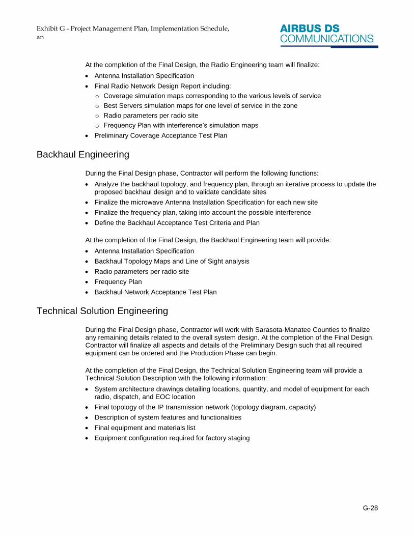
Exhibit G - Project Management Plan, Implementation Schedule, an
G-28
At the completion of the Final Design, the Radio Engineering team will finalize:
Antenna Installation Specification
Final Radio Network Design Report including:
o Coverage simulation maps corresponding to the various levels of service
o Best Servers simulation maps for one level of service in the zone
o Radio parameters per radio site
o Frequency Plan with interference’s simulation maps
Preliminary Coverage Acceptance Test Plan
Backhaul Engineering
During the Final Design phase, Contractor will perform the following functions:
Analyze the backhaul topology, and frequency plan, through an iterative process to update the proposed backhaul design and to validate candidate sites
Finalize the microwave Antenna Installation Specification for each new site
Finalize the frequency plan, taking into account the possible interference
Define the Backhaul Acceptance Test Criteria and Plan
At the completion of the Final Design, the Backhaul Engineering team will provide:
Antenna Installation Specification
Backhaul Topology Maps and Line of Sight analysis
Radio parameters per radio site
Frequency Plan
Backhaul Network Acceptance Test Plan
Technical Solution Engineering
During the Final Design phase, Contractor will work with Sarasota-Manatee Counties to finalize any remaining details related to the overall system design. At the completion of the Final Design, Contractor will finalize all aspects and details of the Preliminary Design such that all required equipment can be ordered and the Production Phase can begin.
At the completion of the Final Design, the Technical Solution Engineering team will provide a Technical Solution Description with the following information:
System architecture drawings detailing locations, quantity, and model of equipment for each radio, dispatch, and EOC location
Final topology of the IP transmission network (topology diagram, capacity)
Description of system features and functionalities
Final equipment and materials list
Equipment configuration required for factory staging

Exhibit G - Project Management Plan, Implementation Schedule, an
G-29
Site Development Services
Contractor will manage site development in concert with its subcontractor, Black and Veatch. Contractor will provide design schematics and details for all sites for Sarasota-Manatee Counties’ approval, covering the following:
Permitting
FAA and FCC filings and authorizations
Site preparation
New towers and shelters
Shelter upgrades
Structural analyses
UPS systems
DC power systems
Generator systems
Grounding systems
Lightning and surge protection systems
Preliminary Design
During the Preliminary Design phase, Contractor will perform a detailed technical site survey and inspection of each existing radio site with Sarasota-Manatee Counties.
The goal of the technical site survey is to identify any required site remediation or improvements that may be required to support deployment of the Contractor’s provided system. This is done to identify issues that can be addressed as part of the overall site design process. Individual site layout drawings will be created for each site to assist in the placement of equipment within the space available and to coordinate equipment placement during the creation of installation plans and diagrams.
Upon completion of the technical site survey activity, a formal design will be prepared for each site. The site development team will move forward with the necessary permitting process and the preparation of formal installation plans and specifications.
Final Design
During the Final Design phase, Contractor will finalize all details of the site development process and provide design documentation for the Sarasota-Manatee Counties’ approval.
Site Construction
The Contractor’s Deployment Manager will closely monitor the sites construction progress ensuring all sites are being prepared to plan and to schedule. While the system is being fabricated and tested at the staging facility, the Project Manager will be communicating with Sarasota-Manatee Counties on providing civil works and sites statuses, while ensuring each radio and dispatch site is prepared and ready for the installation of system equipment. This will include close coordination with Sarasota-Manatee Counties regarding the schedule and progress.

Exhibit G - Project Management Plan, Implementation Schedule, an
G-30
Additionally, the Deployment Manager will be coordinating the installation of both the RF and Microwave antennas and lines for each of the radio sites. The goal of this activity will be to have the antenna installation completed and the sites fully prepared just prior to the Sarasota-Manatee Counties-witnessed Factory Acceptance Test so that the system can be shipped directly to the field and installed.
During the site preparation the implementation and construction team will be responsible for the following:
Tracking and managing inbound equipment and materials
Coordinating and scheduling of the civil construction and site development
Coordinating tower installation crews (RF and Microwave)
Coordinating and managing the installation activities
Working through and resolving field construction issues
Ensuring that all antenna installations are validated and tested upon installation
Performance of the Site Readiness Inspection with the customer
Managing the resolution of any Site Preparation Punch-list items
Site clean-up
Microwave Backhaul
For the microwave system, Contractor will perform an end-to-end test of the installed microwave hops to validate and document its performance. For Sarasota-Manatee Counties-provided portion of the networks, it will be requested that Sarasota-Manatee Counties perform an end-to-end validation to ensure that the supplied backhaul network meets the performance requirements of the technical solution and that any issues identified can be addressed without placing the overall project schedule at risk.
Site Readiness
At the conclusion of site preparation, the Deployment Manager will perform a formal Site Readiness Inspection with Sarasota-Manatee Counties to ensure that all pre-installation tasks have been completed in accordance with contract requirements and to the satisfaction of Sarasota-Manatee Counties. This also certifies that the sites are ready for the installation of system equipment. As part of the Site Readiness Inspection, antenna sweeps for each antenna installed will be reviewed.
At the completion of the site development and preparation, Contractor will provide the following:
Site Readiness Inspection results and punch-list
Installation schedule updates

Exhibit G - Project Management Plan, Implementation Schedule, an
G-31
General Exclusions
Without the benefit of a formal engineering analysis, all existing structures (towers) are assumed structurally sufficient to support the proposed antenna system equipment and lines. If, after an engineering analysis, a structure is found deficient and requires modification, replacement or relocation to an alternate site then the services and related costs to remedy or relocate will be quoted by Contractor under a separate scope.
Contractor will provide a separate set of drawings which specify the tower modifications needed, performance of the necessary tower upgrades, a subsequent analysis which reflects a passing result considering the modifications, and a final inspection to ensure the modification work was completed properly.
System Implementation Services
Final Design Phase
During the Final Design phase, the team will be focused on the design, interfacing, and integration of system components into a single cohesive solution. From a site infrastructure perspective this will include finalizing the equipment locations, infrastructure wiring, cross-connections, and installation details for the supplied equipment. In addition, a detailed production package will be developed in preparation for the staging production run and factory provisioning inclusive of component racking, interconnection, and wiring along with the establishment of baseline (factory) settings for all equipment. The team will also identify and vet interfaces between external systems and components in preparation for field integration.
Production Phase
During the System Production phase, the Deployment Manager has overall responsibility for the coordination, fabrication, and testing of the factory staged system and for ensuring the quality of the build. Upon completion of fabrication activities, the Deployment Manager coordinates with Quality Assurance and the System Integration Engineer to perform a final inspection of each rack assembly for adherence to production requirements and fabrication standards. Once all remediation items have been completed, the System Integration Engineer will have responsibility for the factory provisioning of the system. Upon completion of the factory provisioning, the system is then integrated with other subsystems, tested, and prepared for the Factory Acceptance Test (FAT). Microwave equipment will be staged separately from the radio system.
During the System Production phase, the implementation team will be responsible for the following:
Tracking and managing inbound equipment and materials in support of the build
Performing inbound inspections and addressing any non-conformance issues
Tracking progress of the build and meeting project schedule requirements
Ensuring that staging services are provided in accordance with the final design review documents
Managing the production change control process
Managing and overseeing the fabrication of the System

Exhibit G - Project Management Plan, Implementation Schedule, an
G-32
Ensuring the installation and connectorization of all cabling
Ensuring all cabling is labeled in accordance with manufacturing standards
Performing the post-production Final Assembly Inspection
Performing factory provisioning including the programming and configuration of all equipment
Ensuring the configuration and validation of the equipment and subsystems to be staged
Tracking and maintaining site-by-site inventories
Coordinating third party equipment to be utilized and tested during System Production
Staging and setting up equipment on a site-by-site basis in the deployed configuration
Conducting pre-FAT testing of the System
Coordinating and conducting client witnessed FAT
Arranging for crating and shipment to market of all equipment
Providing System documentation
Site Installation
The site installation stage includes the physical installation, integration, and interconnection of the System equipment, rack assemblies, and supplied components at each of the radio and dispatch sites. Site installation is managed and overseen by the Project Deployment Manager.
At the conclusion of site installation, the Deployment Manager will perform a Site Installation Inspection with Sarasota-Manatee Counties to prepare for formal Site Acceptance, to ensure that all installation tasks have been completed in accordance with contract requirements and that the sites are ready for commissioning by Contractor’s System Integration Engineer.
During site installation, the implementation team will be responsible for the following:
Tracking and managing equipment and materials shipments to site
Coordinating and managing the installation schedule
Coordinating placement of console components and Control Station Radios with Sarasota-Manatee Counties
Managing and overseeing the installation of site equipment including:
o Core server equipment racks and components
o Radio equipment racks and components
o Radio consoles and CSR equipment
o Network equipment and components
o Backhaul equipment
Ensuring that all equipment is installed in accordance with plans and specifications
Ensuring that all equipment is correctly connected to power and grounded
Working through and resolving field installation issues
Inspecting all site installation activity for adherence to plans and specifications
Performance of the Site Installation Inspection with the client
Managing the resolution of the Site Installation Inspection Punch-list items

Exhibit G - Project Management Plan, Implementation Schedule, an
G-33
System Provisioning
System Provisioning includes the final system setup and configuration of equipment to meet operational requirements and site conditions. System Provisioning is overseen by the Deployment Manager but is the direct responsibility of Contractor’s System Integration Engineer. Site Provisioning begins with the final configuration of the WAN network and the “standing-up” of the network to establish site-to-site interconnectivity and communication across the network. Once the network is “stood-up” the System Integration Engineer will perform the final RF provisioning at each site and will optimize the system.
Once completed, the Deployment Manager will coordinate with Sarasota-Manatee Counties to perform the formal Site Acceptance activity for each site. At that point, the System Integration Engineer will set up the System to facilitate drive testing for coverage validation. The System Integration Engineer will continue System deployment including testing and validating third-party interfaces, configuring the System with Sarasota-Manatee Counties-supplied data, and preparing for System Acceptance Testing.
During the System Provisioning the integration team will be responsible for ensuring the following:
All equipment is powered up and working properly
All equipment is properly installed and consistent with System plans and specifications
All equipment is provisioned and configured properly
All electrical and power levels meet design and manufacturer requirements
WAN and LAN links performance is consistent with P25 system requirement
All audio and data levels are checked and set correctly
Passive components (filters, cavities and duplexers) are swept
Top of Rack output power levels are checked and meeting design requirements (forward and reflected)
Power output on all channels is balanced
TTA and RX multicoupler attenuation is set and meeting design requirements
Communication interfaces between devices are operating properly
The final device discovery is performed for the network alarm manager
The alarm aggregators at each site are programmed and system alarming is verified
System configuration is in accordance with the Network Equipment Configuration document
Sarasota-Manatee Counties-provided subscriber unit and talkgroup information has been loaded
Console system operation has been checked and verified
Control station radios have been installed and tested
All required site RF testing has been performed
The System is ready for drive testing and System acceptance
At the completion of System Provisioning, Contractor will provide the following:
Site commissioning and site RF testing results
Site Acceptance Test Report

Exhibit G - Project Management Plan, Implementation Schedule, an
G-34
Cutover Overview
Contractor has proposed a Preliminary Cutover and Transition Plan, and will work closely with Sarasota-Manatee Counties to finalize this plan. See Cutover Plan below.
Contractor’s Deployment Manager has the responsibility for the preparation, coordination, and performance of the initial system cutover and user migration in accordance with a mutually developed cutover plan coordinated with Sarasota-Manatee Counties. The Cutover will take place after a successful execution of both the System and Coverage acceptance testing and approvals.
Decommissioning
Contractor’s Deployment Manager will have responsibility for the coordination and removal of the existing system equipment. Decommissioning and removal of equipment will be in accordance with contract requirements and in coordination with Sarasota-Manatee Counties.

Exhibit G - Project Management Plan, Implementation Schedule, an
G-35
Training Services
Training Scope
Contractor will coordinate and oversee the delivery of all training, including partner training for the following scope of systems:
Airbus DS Communications VESTA Radio
Zetron Dispatch Console
Microwave Equipment
User Equipment
Training Delivery is provided based on the needs of each type of user:
Tactical – Communication Managers and Supervisors
Technical – System Administrators
Maintenance – Service and Support Personnel
Training Plan
Contractor will prepare a comprehensive training plan for Sarasota-Manatee Counties’ approval, which shall include training for:
Dispatchers
Field Radio Users
System Management
Subscriber Equipment Programming
Subscriber Equipment Repair/Maintenance
Training Seminars
The training seminars shall include the following:
Distribution of training literature
A presentation of the general communications equipment and System theory, configuration, and features
A description of routine communications procedures, features and functions, and demonstrations with hands-on participation
Equipment operation and user training
Equipment programming and template development
System management training
System troubleshooting and maintenance

Exhibit G - Project Management Plan, Implementation Schedule, an
G-36
Verification and Acceptance Testing
During the System Acceptance Testing phases, Contractor will demonstrate the conformance to the agreed upon requirements to Sarasota-Manatee Counties. The Acceptance procedures are divided into phases corresponding to the project phase and each will conform to the approach specified within the Acceptance Test Plan. The specific procedures are described in the following sub-sections.
Factory Acceptance Testing
Factory Acceptance Testing is a preliminary test to demonstrate system functionality, operation, and performance. This test is performed in the staging facility within a well-controlled environment to ensure the initial development of the System conforms to requirements. The test will be performed according to the Factory Acceptance Test Plan, which will be provided to Sarasota-Manatee Counties a minimum of 30 days prior to the commencement of the test. Contractor has allowed one week for the Sarasota-Manatee Counties to approve the test plan.
Coverage Acceptance Testing
Radio Coverage Acceptance Testing comprises:
Automated BER and informational signal level tests
DAQ 3.4 voice quality tests for inbound and outbound messages
In-building testing of the critical and mandatory buildings per the agreed upon list.
Detailed test procedures are provided in the draft Coverage Acceptance Test Plan.
Contractor will complete the coverage test plan, including specific drive routes and deliver it to Sarasota-Manatee Counties a minimum of 30 days prior to the commencement of the test. Contractor has allowed one week for the Sarasota-Manatee Counties to approve the test plan.
Final System Acceptance Testing
Final System Acceptance Testing comprises a functional test to demonstrate end-to-end system performance of the delivered VESTA Radio system, and conformance to requirements. This test will be used to provide the final acceptance of the installed system, testing the performance and conformance to the agreed upon requirements. The test will be performed according to the System Acceptance Test Plan, which will be provided to Sarasota-Manatee Counties a minimum of 30 days prior to the commencement of the test. Contractor has allowed one week for the Sarasota-Manatee Counties to approve the test plan.
System testing shall also demonstrate that all site development responsibilities have been fully achieved.
30-Day Operational Test Period
The Operational Test Period will demonstrate that the System is performing as intended and without interruption.

Exhibit G - Project Management Plan, Implementation Schedule, an
G-37

Exhibit G - Project Management Plan, Implementation Schedule, and Cutover Plan 800 MHz Emergency Communications Systems For Sarasota and Manatee Counties
RFP 142842TM
G-38
Work Breakdown Structure
Figure 7 WBS, Sarasota-Manatee Counties 800 MHz P25 Public Safety Radio Network

Exhibit G - Project Management Plan, Implementation Schedule, and Cutover Plan h 800 MHz Emergency Communications Systems For Sarasota and Manatee Counties
RFP 142842TM
G-39
Responsibility, Effort, and Checklist of Activities
Sarasota-Manatee Counties' Responsibilities and Effort
Successful delivery of all project requirements depends on collaborative support from both Contractor and the Counties that is timely, collaborative, and vested with knowledge of all stakeholder operations and sensitivities. Contractor will not only meet its obligations, but will work very closely with the Sarasota-Manatee Counties to ensure that Contractor supports the Counties in meeting their obligations.
As a guiding principle, the Counties will be responsible for supporting project delivery by participating in all joint Counties/Contractor project management meetings and acting on any mutually agreed upon follow-up activities, and for providing timely input and feedback on design and configuration issues and options, particularly related to integrating existing equipment. In order to meet these obligations, Contractor anticipates that the Counties will each assign a Project Administrator that has authority and access to involve and/or solicit input from various Counties’ departments for the purposes of resolving contractual, operational, technical, maintenance support, administrative issues, options, etc.
Contractor anticipates the Counties’ Project Administrators will, on average, be utilized approximately 80% of the time. Greater effort is anticipated at the beginning and end of the project during the planning phase and verification and cutover phases respectively. Less effort is anticipated while Contractor is actually building and implementing the System and sites.

Exhibit G - Project Management Plan, Implementation Schedule, and Cutover Plan h 800 MHz Emergency Communications Systems For Sarasota and Manatee Counties
RFP 142842TM
G-40
Table 6 Role Requirements
Role Number of
Staff Required
Estimated Start Date (month)
Duration Required
County Project Administrator
2 (One per County)
June-15
60% of the time throughout the entire project Greater effort is anticipated during the planning, verification, and cutover phases Less effort is anticipated during the building and implementation phase.
Project Manager 1 June-15 Fully dedicated to the project throughout the entire project.
Finance Controller 1 June-15 20% of the time Greater effort at project Kick off and close.
Project Quality Manager
1 June-15 20% of the time throughout the entire project for quality gates and QA/QC.
Technical Solutions Engineer
1 June-15 22 months, however a greater participation is to be expected during the planning and design phases
Transmission Network Engineer
1 June-15
22 months, however a greater participation is to be expected during the planning and design phases as well as testing Less effort during the installation
Radio Network Engineer
1 June-15 7 months mostly during the design period and the CATP write up, drive tests, and report
Implementation 5 June-15
20 months. Starting in October (Kick off) but greater effort expected starting in January with Zoning & Permitting, Staging, Construction, and Installs
Care Manager 1 May 17 Light effort during the project. Greater involvement at warranty start
Training Manager 1 Feb 17 2/3 months to prepare training sessions and documents, meetings with Sarasota-Manatee Counties, provide training.
Radio System Manager
1 May 17 Light effort during the project. Greater involvement at warranty start

Exhibit G - Project Management Plan, Implementation Schedule, and Cutover Plan h 800 MHz Emergency Communications Systems For Sarasota and Manatee Counties
RFP 142842TM
G-41
Checklist of Typical Activities
The following checklist highlights many of the project activities that Contractor will perform, along with the activities that the Counties will need to support or take responsibility for. Activities are categorized according to the major project implementation phases presented in Implementation Process and Quality Assurance Management above, including:
Project Mobilization
Infrastructure Planning and Design
Site Development
Factory Staging
Site Installation – Equipment
Subscriber Equipment
Training
Verification Testing
Cutover
Project Completion
This list is not exhaustive and more detailed provisions of this Project Management Plan take precedence as the prevailing guide for apportioning activities and responsibilities.

Exhibit G - Project Management Plan, Implementation Schedule, and Cutover Plan h 800 MHz Emergency Communications Systems For Sarasota and Manatee Counties
RFP 142842TM
G-42
Table 7 Checklist of Activities
Support = S Responsible = R
Sarasota-Manatee
Counties Airbus DS
Communications
Tasks Sarasota Manatee hrs R/S hrs Comments
Project Mobilization
Appoint Project Administrator with approval authority
R R 1 R 1 Each County should have representative identified
Project Status Meetings – Bi-Weekly
S S 2-4 R 6 Status meeting prep time and actual meeting time
Project Kickoff Meeting S S 16 R 40
Contractor will coordinate with the Counties on kickoff meeting schedule and location.
Review Project Timeline S S 16 R 40 Finalize project schedule
Project Management Plan Review and Finalize
S S 16 R 40
Contractor will solicit and incorporate feedback from the Counties.
Infrastructure Planning and Design
Review of coverage requirements S S 2 R 32
Review list of proposed candidate sites - Filings
S S 8 R 80
Contractor will fill out paperwork required for submissions. Duration in project schedule is expected duration from agencies
Preliminary Design Discussions S S 16 R 80
High level review of proposed system design to validate assumptions and clarify open questions
Preliminary Design Review S S 80 R 300
Document prep, review, and revisions. Majority of time will be Contractor developing documents for review by Counties
Final Design Review S S 32 R 240
Document prep, review, and revisions. Majority of time will be Contractor developing documents for review by Counties
Prepare Detailed WBS S S 4 R 40
Finalize Cutover and Transition Plan
S S 8 R 80
Site Development

Exhibit G - Project Management Plan, Implementation Schedule, and Cutover Plan h 800 MHz Emergency Communications Systems For Sarasota and Manatee Counties
RFP 142842TM
G-43
Sarasota-Manatee
Counties Airbus DS
Communications
Tasks Sarasota Manatee hrs R/S hrs Comments
Zoning and Permits S S 40 R 300
Contractor will perform all of the permitting and zoning functions. Counties will assist in any expedites.
Construction Drawings S S 80 R 200
Contractor will develop CD package. Counties will review and comment. Counties will provide any existing drawings.
Site Access R R 18 S 18
The Counties will be responsible for site access contacts and authorizations
Perform Site Mechanical Inspections and Tests
S S 60 R 180
Contractor will inspect and test prior to County involvement. Counties will witness any contractual tests and review documentation
Factory Staging
Develop system test documentation
S S 40 R 120 Contractor will develop documentation and the Counties will review
Witness staging tests R R 24 R 24
Formal staging tests are expected to take 3 days. The Counties will be responsible to travel to designated staging area.
Authorize equipment shipment to field
R R 2 S 20
The Counties will authorize shipment and Contractor will pack and ship.
Site Installation - Equipment
Existing equipment S S 18 R 80
Temporary equipment locations need to be identified where shelter space is limited.
Microwave Readiness Tests S S 36 R 54 The Counties will either witness link tests or review documentation.
Antenna Sweep Tests S S 36 R 120 The Counties will review antenna sweeps.
RF System Readiness Tests S S 36 R 32
The Counties will witness any agreed upon equipment testing (4 hrs per site)
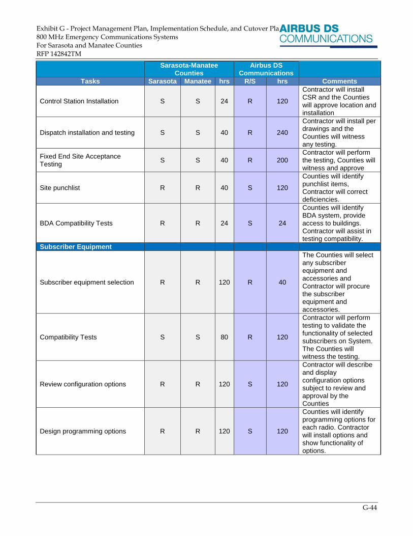
Exhibit G - Project Management Plan, Implementation Schedule, and Cutover Plan h 800 MHz Emergency Communications Systems For Sarasota and Manatee Counties
RFP 142842TM
G-44
Sarasota-Manatee
Counties Airbus DS
Communications
Tasks Sarasota Manatee hrs R/S hrs Comments
Control Station Installation S S 24 R 120
Contractor will install CSR and the Counties will approve location and installation
Dispatch installation and testing S S 40 R 240
Contractor will install per drawings and the Counties will witness any testing.
Fixed End Site Acceptance Testing
S S 40 R 200 Contractor will perform the testing, Counties will witness and approve
Site punchlist R R 40 S 120
Counties will identify punchlist items, Contractor will correct deficiencies.
BDA Compatibility Tests R R 24 S 24
Counties will identify BDA system, provide access to buildings. Contractor will assist in testing compatibility.
Subscriber Equipment
Subscriber equipment selection R R 120 R 40
The Counties will select any subscriber equipment and accessories and Contractor will procure the subscriber equipment and accessories.
Compatibility Tests S S 80 R 120
Contractor will perform testing to validate the functionality of selected subscribers on System. The Counties will witness the testing.
Review configuration options R R 120 S 120
Contractor will describe and display configuration options subject to review and approval by the Counties
Design programming options R R 120 S 120
Counties will identify programming options for each radio. Contractor will install options and show functionality of options.

Exhibit G - Project Management Plan, Implementation Schedule, and Cutover Plan h 800 MHz Emergency Communications Systems For Sarasota and Manatee Counties
RFP 142842TM
G-45
Sarasota-Manatee
Counties Airbus DS
Communications
Tasks Sarasota Manatee hrs R/S hrs Comments
Design any mobile install templates
S S 120 R 120 Contractor will work with the Counties to design mobile templates
Perform field testing R R 80 S 40
The Counties will test in field for programming accuracies and Contractor will make the necessary corrections
Revise templates and retest R R 80 S 80
Template, mobile and control station install design approval
R R 80 S 80
Program subscriber radios S S 400 R 400
Distribute portables per cutover plan
R R 200 S 100
The Counties will identify distribution method and coordinate with field reps
Install and deploy mobiles per cutover plan
R R 300 S 400
Contractor will contract local shop to install, the Counties will identify which vehicles receive which mobiles.
Training
Develop training plan S S 40 R 40
Contractor will describe programs and the Counties will select programs
Approve training plan R R 40 S 8 Training plan subject to approval by the Counties.
Schedule training sessions R R 80 S 20
The Counties will identify available weeks for training and make appropriate individuals available.
Perform primary training classes S S 20 R 200
Contractor will perform. Hours do not include individual class participant hours
Perform secondary training classes
R R 200 S 20
The Counties will perform secondary classes after train the trainer classes
Verification Testing
System optimization testing S S 80 R 120 Testing and witness
Customer Witnessed Drive Testing
R R 80 R 80 Per person participant
Customer Witnessed CATP R R 80 R 80 Per person participant
Functional Acceptance Test Plan S S 120 R 200 Perform testing

Exhibit G - Project Management Plan, Implementation Schedule, and Cutover Plan h 800 MHz Emergency Communications Systems For Sarasota and Manatee Counties
RFP 142842TM
G-46
Sarasota-Manatee
Counties Airbus DS
Communications
Tasks Sarasota Manatee hrs R/S hrs Comments
Test documentation S S 20 R 80
Contractor will develop documentation and the Counties will review and accept the documentation
Cutover of system for 30 day test S S 40 R 80 Planning and execution estimates
Support 30 day test R R 20 R 80
Approve 30 day acceptance R R 4 S 4
Project Completion
Provide system as-built documentation
S S 40 R 200 Contractor will develop and the Counties will review
Decommission old equipment S S 40 R 320 Estimated one field crew and one tower crew per County
Resolution of any punchlist items S S 10 R 40
Final acceptance approval R R 2 S 2
Cutover Plan
The transition of both Sarasota and Manatee County agencies from their respective legacy systems will be coordinated and the responsibility of the Contractor’s Project Deployment Manager. The Deployment Manager (DM) will have direct responsibility to each County for the preparation, planning, coordination and performance of the cutover and system migration activities. The system cutover and user migration is seen as a mutual activity between Contractor and each of the County Project teams to ensure a positive experience for County users and to ensure as small of an impact as possible on County operations.
While the transition from the existing radio network is anticipated to be similar for each County, Contractor’s team will work with both Counties together and independently to understand operational methodologies, user behavior and fleet dynamics in planning and coordinating the user migration. This will allow Contractor’s team to finalize and deliver the required detailed cutover plan within sixty (60) days after completion of the system review.
The suggested strategy is expected to utilize a “parallel-operation” phased migration in accordance with this Agreement. This offers the benefit of a phased and orderly migration of system users from one system to the next while maintaining the safety net of both systems operating in parallel.
Transition Process
Contractor utilizes a 7-phase transition process for implementing new systems that is comprised of the following steps:
Phase 1—Planning and Coordination
Phase 2—Provisioning and Interfacing

Exhibit G - Project Management Plan, Implementation Schedule, and Cutover Plan h 800 MHz Emergency Communications Systems For Sarasota and Manatee Counties
RFP 142842TM
G-47
Phase 3—Preparation and Validation
Phase 4—Cutover Commencement
Phase 5—Cutover
Phase 6—Post Cutover Observation and Performance Test Period
Phase 7—Operation and Care
These 7 phases are represented in the following diagram:
7654321
P25 OPERATION
SYSTEM
INSTALLATIONS
FIELD
PROVISIONING
SYSTEM
VALIDATION
GROUP
PREPARATION
GROUP
MIGRATION
GROUP
OBSERVATION
CARE &
MONITORING
MIGRATION BY
GROUP
SITE
ACCEPTANCE
TESTINGCOVERAGE
TESTING END-TO-END
SYSTEM
TESTING
STABILITY /
BURN-INCONTINUAL SYSTEM
ASSESSMENT
CUTOVER PLANNING &
COORDINATION
SESSION
DISPATCH CONSOLE
EQUIPMENT MOCK-UP
FINAL SCREEN BUILDER
WORKSHOP
FLEET MAPPING
CODE PLUG
DEVELOPMENT
REGIONAL
INTEROPERABILITY
COORDINATION
SYSTEM PROVISIONING
SUBSCRIBER
INSTALLATIONS
SUBSCRIBER
PROGRAMMING &
VALIDATION
LEGACY SYSTEM
INTERFACING
ISSI INTERCONNECTIVITY
& TURNUP
DISPATCH INSTALLATION
SYSTEM / MAINTENANCE
TRAINING
PL
AN
NIN
G
FINAL CUTOVER
PLANNING SESSION
USER GROUP
DETERMINATIONS
COVERAGE TESTING
SYSTEM PERFORMANCE
TESTING
RESILANCY /
REDUNDANCY TESTING
END-TO-END SYSTEM
VALIDATION
TEST READINESS REVIEW
DISPATCHER /
SUBSCRIBER TRAINING
CUTOVER GO / NO GO
MEETING
GROUP SCHEDULING &
USER COMMUNITY
NOTIFICATIONS
FAIL-BACK
COORDINATION
TRANSITION EVENT
SEQUENCING
COMMUNICATION &
ISSUE REPORTING
PLANNING
PREPOSITION / PRE-
TESTED PORTABLE
TROUBLE CACHE & USER
MATERIALS
USER GROUPS
MIGRATED PER
SCHEDULE
PRE/POST SYSTEM
SNAPSHOT
SYSTEM IS ACTIVELY
MONITORED
THROUGHOUT THE
MIGRATION
REPORTED FIELD
ISSUES ARE TRIAGED &
INVESTIGATED
GROUP IS MONITORED
UNTIL STABILIZED
MIGRATION ISSUES AND
REQUIRED ACTIONS
ARE REVIEWED
ANY REMEDIATION IS
APPLIED
GROUP MIGRATIONS
ARE COMPLETE
SYSTEM TRANSITIONS
TO NORMALIZED CARE
FINAL SYSTEM
SNAPSHOTS AND
CONFIGURATIONS ARE
CAPTURED
SYSTEM
DOCUMENTATION IS
UPDATED TO REFLECT
THE ACTIVE STATE
REMAINING LEGACY
EQUIPMENT IS
DECOMMISSIONED
P25 OPERATIONSIDE-BY-SIDE OPERATION (LEGACY & P25)LEGACY OPERATION
CONSOLE OPERATION
BLENDED FLEET (LEGACY & P25)P25 READY – LEGACY OPERATIONLEGACY OPERATION
SUBSCRIBER OPERATION
CUTOVER - PARALLEL OPERATION / PHASED MIGRATION
Figure 8 Cutover Diagram

Exhibit G - Project Management Plan, Implementation Schedule, and Cutover Plan h 800 MHz Emergency Communications Systems For Sarasota and Manatee Counties
RFP 142842TM
G-48
Phase 1—Planning and Coordination
Phase 1 of the transition to the System will include a number of cutover planning and coordination sessions with the Counties to walk-through the System cutover process, coordinate the required details and start preparing for the cutover event. Typically, this is done through the creation of a working group including key members of the Contractor’s project team along with 7 to 10 key stakeholders from the Counties and affected agencies. Having a number of key agency stakeholders provide feedback both into the working group and then back to the user community is of enormous value in aiding the adoption of new technology and products. This format where the Counties are an integral part of the process also establishes and reinforces a communication framework where users feel their concerns are expressed, considered and taken into account in the planning and implementation of the VESTA Radio P25 system.
During this phase, Contractor’s team will also conduct a series of form and fit activities with representatives from the Counties’ Project Team including key stakeholders (dispatchers, officers, and vehicle operators) to test fit console components and vehicle equipment to ensure ergonomic and efficient placement of equipment. This test fit will normally involve mocking up or installing a dispatch console position with actual dispatch equipment so that dispatchers and dispatch supervisors have an opportunity to rotate through and provide feedback on component placement while getting a preview of the equipment prior to installation. Another key form and fit activity for dispatch operations is the screen builder workshop. Included in this workshop is the operational dispatch capture to ensure that the dispatch screens are laid out in an efficient manner and are a good match not just functionally but also operationally to the dispatch environment.
A mock-up and installation of a cruiser and other emergency vehicles is also anticipated in order for officers and other first responders to provide feedback in regards to where equipment is placed and positioned within their work environment. Often overlooked, but highly critical is a review for serviceability usually carried out with the radio technicians and other service professional who have extensive experience in working on County vehicles. Often, the County technicians and vehicle service professionals provide insight into future equipment planning beyond that of the radio system and can identify areas where modifications to existing installations may be changed or improved to lower out-of-service and equipment replacement times.
Given the amount of time it can take to perform an accurate and complete fleet-mapping, this process is anticipated to start early in the system transition cycle to allow time to collect and then roll-up information from all County agencies. Often the most challenging part is obtaining vehicle information for critical in-service vehicles that are in continuous use and therefore, unavailable. It is the County’s participation and emphasis on reinforcing the necessity of the activity to the user community that will be critical in obtaining an accurate fleet-map.
Code-plug development is another critical activity that can add time to fleet deployments. For this reason, it will be started early in the migration cycle in order that code-plugs can be developed, tested and validated to avoid having to make a code plug modification mid-deployment and recall vehicles and portable subscribers that have just been recently programmed.

Exhibit G - Project Management Plan, Implementation Schedule, and Cutover Plan h 800 MHz Emergency Communications Systems For Sarasota and Manatee Counties
RFP 142842TM
G-49
Should either County elect to procure subscribers directly from another supplier, Contractor, as it does with all customers, offers to the Counties the use of a VESTA Radio P25 demo system. The demo system, which ships in an 8RU rolling transportable rack, will allow the Counties to evaluate manufacturer provided and programmed units from multiple suppliers with respect to their over-the-air performance on an actual P25 system that can be setup in a conference room. This is possible through Contractor’s use of the industry’s only true IP-based core technology in its VESTA Radio P25 product allowing it to be easily scaled down to a single, virtualized server for this purpose.
Phase 2—Provisioning and Interfacing
Phase 2 of the transition to the System includes the final provisioning of the core, loading of the County fleet and talk-group data and adjusting final system parameters for individual network and actual site conditions. As part of this phase, updates are provided to system components and all third party interfaces are checked and re-verified in their installed state prior to undertaking and beginning the formal battery of acceptance tests.
Building on the work done in Phase 1 and the approvals received from the Counties regarding the vehicle mockups and equipment placement, the Contractor’s team will begin the subscriber mobile installations for the fleet at the Counties’ designated facilities. It is anticipated that the facility provided by each County will be capable of storing sufficient materials for the mobile installation crews to support at least a week’s worth of mobile installations and that the facility will be of sufficient size to allow multiple vehicle installations to occur at the same time. Mobile radios will be programmed at the time of installation and will undergo an installation inspection inclusive of both a test for manufacturer specified performance and an over-the-air operational test to ensure that any installation or performance issues are addressed prior to the vehicle leaving the installation facility.
Phase 2 will incorporate the programming of all subscribers with the approved and tested radio personality / code plug. Contractor has included two rounds of programming for the subscribers. This will allow for optimization of the code plugs after the initial installation and for the removal of any legacy system parameters upon the completion of the cutover activities. All subscribers will be tested to manufacturer specifications at the beginning of the process whether new or County supplied to guard against defective or out-of-tolerance radios being distributed to the fleet. If either County elects to proceed with the purchase of the Contractor’s proposed subscribers, Contractor will provide the necessary programming software, firmware, licenses and programming cables necessary to complete the radio programming. Should either or both of the Counties elect to purchase new subscribers from another vendor, it is assumed that the necessary programming software, firmware, licenses and programming cables needed to successfully program the radios will be procured as part of the third party order and supplied to the Contractor’s team for use during the programming process. Likewise, it is assumed that the Counties will be responsible for the purchase of any required firmware and licenses from their existing vendor(s) for any existing third party subscribers that are P25-capable and desired to be utilized on the P25 network. For existing P25-capable subscribers it is also anticipated that the Counties will be able to provide the programming software and programming cables necessary to program all legacy equipment.

Exhibit G - Project Management Plan, Implementation Schedule, and Cutover Plan h 800 MHz Emergency Communications Systems For Sarasota and Manatee Counties
RFP 142842TM
G-50
As part of the core provisioning and system installation Contractor will install and deploy interoperability equipment in order to establish eight (8) bridged talk-paths between both the Motorola SmartZone system and Harris EDACS ProVoice system. These talk-paths will be utilized for the cutover to allow interoperability between both legacy systems and the new VESTA Radio P25 consoles being deployed by Contractor. Interoperability will be accomplished on the Sarasota County side through the deployment of eight (8) Zetron Smart Radio Gateways that will be integrated to four (4) Motorola XTL 5000 radios requested to be supplied and programmed for the Motorola SmartZone system by Sarasota County. Similarly, four (4) Zetron Smart Radio Gateways will also be deployed and integrated with eight (8) Harris M7300 radios requested to be supplied and programmed by Manatee County for the EDACS ProVoice system. The radio system consoles provided by Zetron as part of the Contractor’s solution will then be utilized to patch the talk-paths to/from each of the legacy systems to the P25 system and across all three systems if the need should arise.
Phase 2 will conclude with system operator and maintenance training which will aid each County in gaining a more complete understanding of the System and components deployed ahead of the formal testing cycles as the Contractor’s team works towards Final System Acceptance. Having each County trained on the System prior to the start of testing activities provides the baseline knowledge of the management and control interfaces along with the necessary product knowledge to fully participate in the testing process. As an added benefit to the Counties, it also provides an opportunity for some over-the-shoulder training and reinforcement of key System parameters and functions as the team moves through both the pre and formal testing sequences.
Phase 3—Preparation and Validation
Phase 3 will see the conclusion and finalization of any outstanding coordination and planning required for cutover along with a mutual final review of the cutover plan that will be organized by the Deployment Manager with each County. The primary purpose of this final review is to capture any final changes and modifications in order that they can be incorporated into the cutover plan and schedule prior to distribution to all key stakeholders within each of the Counties.
It is anticipated that by Phase 3 that the Contractor’s team and Counties will have made final cutover user group determinations for all affected agencies within the fleet and designated a test group of users to be given advanced access to the System in a non-critical operational (testing) capacity. This test group is the first user group to migrate to the System and consists of advanced system users from key agencies throughout the Counties. The goal of the test group, in addition to exercising the System, is to identify any operational differences between the legacy systems and the System that the user community may be sensitive to. This activity allows any differences in how things operate to be addressed during user training and communicated to the user group in advance of the cutover so they know what to expect. An example of this is alert tones that may be very similar but not exactly matched to what first responders are accustomed to hearing on the legacy system. Another example is the difference between not being able to transmit and a talk-group busy tone that is often interpreted by a user not familiar with a trunking system as “not being able to get out” and ultimately results in a loss of confidence in the system.

Exhibit G - Project Management Plan, Implementation Schedule, and Cutover Plan h 800 MHz Emergency Communications Systems For Sarasota and Manatee Counties
RFP 142842TM
G-51
Very often, small changes are identified by the test group that are utilized to optimize the radio personality or code plugs in order to adjust radio behavior to County expectations for either the entire fleet or a select group of users. This is relatively common as part of deploying a new radio system and new subscribers. A second round of radio programming has been included to incorporate these optimizations. Depending on the optimizations identified and the impact of these optimizations, a determination will be made by the working group whether to optimize prior to cutover or just after once the entire user community has had an opportunity to use the System.
This phase also incorporates the critical testing activities necessary to guarantee and demonstrate the System’s performance prior to placing critical users on the network and to make any final System optimizations that may be required to match the deployed System to field conditions. All collected System and test data is analyzed and reviewed by the Contractor’s design team as well as County stakeholders. Included in the Contractor’s standard testing regimen is an optimization drive-test that is utilized to adjust, when required, frequency offsets, timing delays (launch delay) and output power levels to achieve the required coverage goals of the System. Once optimizations are completed, the drive-test is performed again to validate that any System changes have achieved the desired results. Only once the System is optimized will the Contractor’s team recommend proceeding with formal witnessed coverage testing. Representatives from the Counties are encouraged to participate in all phases of testing with the understanding that the pre-testing and optimization activities serve the purpose of getting to an optimized result and preparing the System for formal witness and acceptance testing and are not designed to achieve an optimized result on the first test.
As part of the System testing, Contractor’s team will undertake a number of redundancy and resiliency tests to ensure that the RF network failover scenarios occur in accordance with design parameters and expectations and that the network re-converges and responds as expected. This is important in establishing both the resiliency of the radio network but also to ensure that the fallback plan to the legacy network can be performed flawlessly and that it occurs in a predictable and controlled manner.
The final testing battery includes both end-to-end operational testing and use cases that make-up the System Acceptance Testing. The goal is to test the System as it is intended to be used with real-world scenarios. It is fully expected and encouraged that the Counties participate in the development and modification of the various test-cases that the Contractor’s team will put forward for final System Acceptance Testing. This will ensure that the Counties see the System tested in a manner applicable to each County’s operations and not just using stock manufacturer procedures created to provide optimal results for testing purposes.
The Contractor’s team recognizes the importance of user and dispatch training and ensuring that training does not go stale prior to cutover, which could leave dispatchers and system users struggling to recall information months in the past. User and dispatch operator training is scheduled towards the end of Phase 3 to ensure that the information is as current as possible as the users and dispatchers transition onto the System.

Exhibit G - Project Management Plan, Implementation Schedule, and Cutover Plan h 800 MHz Emergency Communications Systems For Sarasota and Manatee Counties
RFP 142842TM
G-52
Phase 4—Cutover Commencement
Phase 4 represents the beginning of what Contractor considers the cutover. It begins with the cutover go / no go meeting with County stakeholders where all System testing results, outstanding items and the punchlist status is reviewed in detail with the Counties. The purpose and thoroughness of the review is to ensure that any related impacts from open issues or punchlist items are discussed and understood by the Counties before proceeding with the cutover. Another critical element of this meeting is to identify and discuss any concerns the Counties may have are openly and transparently discussed so they can be immediately addressed and resolved.
At the go / no go meeting the schedule and phasing of cutover groups is again reviewed and any last minute modifications are made and incorporated. It is anticipated at this point that the Counties will issue final user notifications to their affected personnel regarding the schedule along with any operational requirements the Counties require for System users before the cutover. Typically, this communication takes the form of a shift briefing covering the cutover, what to expect, what to bring, what to do when something goes wrong and most importantly who to contact if something isn’t working. A solid communication plan where the users always see a path for resolution of any issue that may arise is key to establishing confidence throughout the user community. It is critical that the users have confidence that should an issue develop, it will be handled expeditiously and that an officer or first responder will not, under any circumstance, be left without a way to communicate in an emergency situation.
Just prior to the cutover event, the joint Contractor and Counties teams tasked with operational responsibility for the cutover will step through, review and practice the established system fallback procedures. This is done in order to ensure the process is understood and fresh in everyone’s mind should an issue occur and fallback be required. The cutover sequence of events is given a final review so that the cutover proceeds logically and methodically as outlined in the developed detail cutover procedure. Most important will be a review of the established communications plan, which allows for information gathering of reported issues and triage procedures to be implemented should they be necessary. This ensures that an issue of lower priority is not being put before reported issues from an officer or first responder.
As part of the planning for the cutover event, it will be the Contractor team’s recommendation that each County establish prepositioned / pre-tested portable caches of radio and user materials throughout the County so that if a user has an issue there is a plan in place for immediate swap-out. Having pre-designated service points that are easily accessible will help in coordinating meeting points in the event that a Contractor System Integration Engineer needs to be dispatched directly to a field location to investigate a reported issue by a user.
Phase 5—Cutover
Phase 5 is the system cutover event where users are actively cutover from the legacy SmartZone and EDACS systems to the System. As this is a phased migration, groups will transfer one or more at a time in accordance with the coordinated migration schedule developed with each County. Each group is transitioned through three phases; planning as part of phase 4, migration as part of phase 5 and then each group will undergo a monitoring period as described in Phase 6. The monitoring period provides time for the Project team to assess and resolve any identified issues before moving on to the next group.

Exhibit G - Project Management Plan, Implementation Schedule, and Cutover Plan h 800 MHz Emergency Communications Systems For Sarasota and Manatee Counties
RFP 142842TM
G-53
The amount of time to migrate all System users is a function of the number of groups to be migrated at one time and the number of migration cycles required to move all affected users and groups to the System. For planning purposes, migration groups are typically spaced 72 hours apart with a group migration usually timed to coincide with the morning shift change and then monitored for a period of 24 to 48 hours before proceeding with the next group.
As part of the cutover, frequencies will need to be migrated from the existing legacy systems (taken down) then put-up on the System in order to increase the System resources and call capacity as more users and groups are cutover to the System. It is expected that the required frequency migration will be based on the number of users being migrated to the System with the migration of frequencies occurring just prior to a group being cutover. A small window of time will be required in order for the Contractor’s team to ensure that channels are successfully brought down on the existing legacy systems and that the new channel groups are successfully placed in service on the System. The time required is a matter of minutes per channel.
Prior to starting the group migration, the System configuration will be backed-up in the event that an issue develops and the System needs to be restored to a previously working state. In practice this often prevents the need to fully fallback to the legacy system as the System can be rolled back to correct an issue if one develops. A System snapshot will also be taken before and after each group migration so the Contractor’s team can assess the impact on System resources and determine if additional channels might need to be migrated in order to prevent the users from having resource contention issues on the System.
To aid in the investigation of a reported field issue, it is suggested that an additional dispatcher be staffed to initial monitor the legacy system for users who have trouble migrating and then to monitor a system trouble talk-group on a normally unused tactical or common talk-group for the System. This process allows a user to report a problem, by manually selecting the talk-group on their radio and can then communicate the issue with a dispatcher without tying up a dispatch channel. Once the report is complete, the user can switch back to their home talk-group and continue with their shift. The Contractor’s team will provide a form to all dispatchers responsible for reporting and recording System issues with all required information for the Contractor’s team to expeditiously pull logs for analysis and identify the specific call within the log data stored in the System servers and repeaters needed to perform an investigation of reported issues. A Contractor System Integration Engineer will be available at the dispatch location to immediately investigate critical System issues in real-time.
During the cutover the Contractor’s team will conduct daily briefings with County stakeholders in addition to the normal interactions to review status, any reported troubles, investigative findings and any suggested remediation. Typically, the daily briefings are hosted via Webex and teleconference to allow maximum participation from County stakeholders and to provide a forum to address management and executive level concerns from the agencies involved.

Exhibit G - Project Management Plan, Implementation Schedule, and Cutover Plan h 800 MHz Emergency Communications Systems For Sarasota and Manatee Counties
RFP 142842TM
G-54
Phase 6—Post Cutover Observation and Performance Test Period
Phase 6 is the group observation period where the Contractor’s team reviews System and performance data to verify the group’s adjustment to the System. This will help to identify users that may be having radio issues or problematic behaviors such as keying up when a talk-group is busy or keying up too quickly (keying up during the hang-time). This allows regular feedback to the Counties’ Project Team of reminders that can be sent out in the daily shift briefings to help the users realize the maximum benefit of the System. The observation period provides the Contractor’s System Implementation and Engineering teams the ability to investigate reported field issues or areas of concern where a call may have been reported to not have gone through or to investigate a field radio that was not performing well and apply any needed remediation.
Upon completion of all group migrations, the System will enter a 30-day performance period prior to being eligible for Final System Acceptance from the Counties. During the performance period, issues that arise will be investigated by the Contractor’s team and resolved. All identified failures or required adjustments with the System will be recorded whether they involve System components or individual subscribers with all issues being reviewed with the Counties’ project team on a weekly basis.
Throughout the project, all identified issues are tracked, cradle-to-grave, using a Remedy database that provides a complete log of System events, investigations and resolutions. The project’s Remedy database is utilized throughout the lifecycle of the System and is accessible via Web login for County System maintainers and administrators. A key feature of this resource is the ability for County personnel to create and monitor technical support cases directly while receiving push notifications regarding issue statuses and posted updates. This will occur in real-time rather than waiting for the next scheduled meeting or briefing. It is strongly encouraged that the Counties utilize this resource as part of the overall system deployment.
Phase 7—Operation and Care
Phase 7 is commonly referred to as the Transfer-to-Care and represents the point in time following Final System Acceptance, users have been successfully migrated off of the legacy systems and onto the System and the System can enter the maintenance phase. Aside from the engagement of System monitoring and the transfer of responsibility to the Contractor’s Technical Support Group, a number of project activities are undertaken to provide an orderly and controlled transition of the project.
As part of Phase 7, the final System configuration, including individual components, will be backed up as part of the as-built record as well as for maintenance purposes. All System documentation is updated to reflect the as-built state at the time the System was placed into production. All third party maintenance manuals, operator manuals, System testing records and as-build drawings are rolled up, organized and delivered to the Counties to meet the as-build documentation requirements and for System maintenance purposes.
This final phase will see the decommissioning of the legacy Motorola SmartZone and EDACS ProVoice equipment along with the removal and strip-out of decommissioned antennas, lines and associated mounts from existing radio sites. All SmartZone and EDACS equipment will be inventoried and delivered to the storage point designated for each County. The Contractor’s team, in coordination with the Counties, will then begin the process to formally closeout the System delivery portion of this Agreement.

Exhibit G - Project Management Plan, Implementation Schedule, and Cutover Plan h 800 MHz Emergency Communications Systems For Sarasota and Manatee Counties
RFP 142842TM
G-55
Transition Schedule
The following figures present the detailed transition schedule.

Exhibit G - Project Management Plan, Implementation Schedule, and Cutover Plan proach 800 MHz Emergency Communications Systems For Sarasota and Manatee Counties
RFP 142842TM
G-56

Exhibit G - Project Management Plan, Implementation Schedule, and Cutover Plan proach 800 MHz Emergency Communications Systems For Sarasota and Manatee Counties
RFP 142842TM
G-57
Cutover Process
In a parallel-operation phased migration, the System equipment will be installed in parallel with the existing legacy system equipment allowing for dispatch operations to remain fully functional on the legacy systems throughout the cutover process. This allows both systems to operate independently and provides individual users and dispatchers several options for moving between the legacy Motorola SmartZone, EDACS ProVoice and System. As part of the overall cutover planning undertaken with the Counties, all or only some of the options may be incorporated to meet the individual needs of the Counties and users in cutting over to the System.
In regard to portable subscribers, there are two options available depending on the capabilities for either native P25 operation or the ability for the units to be upgraded / licensed for P25 operation. For units that are not P25 capable, the option will be to issue an additional P25 subscriber and charger to the user prior to the cutover event and then upon completion of the user migration have the user turn in the legacy radio and charger. In this scenario, during the cutover, the user would carry both units in order to migrate to the System at the appointed time and then keep the legacy radio charged and available in the event a System issue would require falling back to the legacy system to sustain radio communications.
For existing portable subscribers capable of P25 operation, an alternate zone (Motorola) and alternate system (Harris) can be configured in the radio personality / code plug allowing a user to manually roam between the two systems. With this option, both the existing legacy system and the System will be loaded into the radio on the first radio programming cycle providing dual-system capability (if support by the radio) and the user will be trained to move between the two zones or systems to allow them to switch between the existing legacy system and the System. When it is time for these users to migrate to the System, they will simply switch zones or systems to move on to the P25 network. Upon completion of the cutover, the legacy zone or system information can then be removed from the radio personality/code plug on the second radio programming cycle leaving only the P25 configuration. Should fallback be required, it would simply involve moving back to the SmartZone or EDACS system via the radio.
Mobile subscribers will be treated similarly. If the units are not P25 capable, the existing radio will be relocated within the vehicle to a temporary location which still provides easy access and use by the operator. The P25 radio will then be installed in its permanent location with each radio being programmed for the respective system. When it is time for the user to migrate, they will simply switch the radio for the existing legacy system off and the radio for the System on. Fallback for these users will be accomplished via simply using the appropriate radio. Users with P25 capable radios will utilize the dual-zone/dual-system configuration to allow for the user to manually roam between the two systems.
All existing console equipment including the Interim Motorola Gold Elite Console Sub-System to support fifteen (15) Gold Elite Consoles interfaced to the Sarasota Legacy SmartZone Radio System will remain installed and the new P25 console equipment will be collocated with existing console equipment through the cutover and user transition. This will allow a dispatcher to directly fallback to and operate the existing legacy system with the legacy console equipment if the need should arise.
Both Contractor and the Counties’ Project teams will be needed and have responsibilities to ensure a successful and positive transition for the Counties’ users and agencies. The high-level responsibilities which will be further defined as part of the detailed cutover plan are provided below.

Exhibit G - Project Management Plan, Implementation Schedule, and Cutover Plan proach 800 MHz Emergency Communications Systems For Sarasota and Manatee Counties
RFP 142842TM
G-58
Contractor Responsibilities
The Deployment Manager and System Integration Engineer will have the following responsibilities for cutover:
Ensuring the System is fully provisioned, tested and ready to accept System users
Redundancy and System failover has been tested and demonstrated so that there is a solid understanding of failover and graceful degradation of the System
The cutover plan is agreed upon with the Counties and all stakeholders are comfortable and ready for cutover
The System has successfully passed both the Coverage Acceptance Test Plan (CATP) and System Acceptance Testing (SAT)
The fallback process is understood and a plan is in place to fallback the System to a “known good” working configuration should a System anomaly or problem with the cutover occur
All subscriber equipment has been programmed and is ready for migration
The user community has been trained and is informed and ready for the event
Sarasota and Manatee County Responsibilities
Sarasota and Manatee Counties as part of the larger project team will have the following responsibilities for cutover:
Providing eight (8) programmed and compatible existing Motorola XTL 5000 SmartZone radios for integration of the Sarasota County Motorola SmartZone system.
Providing eight (8) programmed and compatible Harris M7300 EDACS radios for integration of the Manatee County EDACS radio system.
If existing P25 capable Motorola and Harris subscribers are to be re-utilized, the Counties shall have responsibility to procure, from the manufacturer, any required firmware or licenses required to upgrade the radios for P25 operation and for providing programming cables and programming software (if needed) to support the reprogramming effort.
If the Counties elect to purchase subscribers other than those offered as part of this Agreement, the Counties shall have responsibility for procuring from the third party all required equipment, firmware, licenses, programming cables and programming software to support the subscriber programming effort.
Assisting and facilitating the interface to Sarasota and Manatee County dispatch personnel to assess their operational needs and so that their specific transitions can be planned for accordingly
Ensuring that all users are afforded the opportunity to receive the appropriate user and dispatch training to minimize support calls during user migration which may result from unfamiliarity with either the radio operation or System behavior
Actively participating in the detailed planning and execution of user migration events
Working with the Contractor’s team to pre-position caches of known-good radios at strategic service points throughout the System in support of user migrations
As frequencies are being reutilized between the System and legacy SmartZone and EDACS systems it will be requested that frequencies are to be transitioned at a rate that avoids any “loss of confidence” in the System due to initial System congestion issues during the transition.

Exhibit G - Project Management Plan, Implementation Schedule, and Cutover Plan proach 800 MHz Emergency Communications Systems For Sarasota and Manatee Counties
RFP 142842TM
G-59
Cutover Steps – Details
A high-level walk-through of the steps to be considered and agreed with the Counties during the detailed cutover/user migration planning are:
Customer and Group Definition
1. Definition of group and user migration timelines:
a. Identify and review specific agency risks against early vs. late cycle migration
b. Examine fleet trends and group operational requirements
c. Review each agency operation and establish criticality
d. Review existing call data for capacity and frequency migration planning
e. Determine frequency availability for the migration
f. Determine frequency groups to be migrated together
2. Definition of user groups:
a. Establish manageable functional migration user groups with Sarasota and Manatee County agencies.
b. Order groups for migration to minimize operational impacts and meet the needs of each County.
c. Identify associated talk-groups required for each user migration group.
d. Identify interoperability talk-groups which are required to support each user migration group.
Note: Both the Motorola SmartZone and Harris EDACS system will be provisioned with 8 talk-
paths which will be utilized to provided system-to-system interoperability with the VESTA Radio
P25 system.
e. Determine the number of channel groups required/available to support each user migration group
f. Establish time needed for fleet reprogramming and operational scheduling for training of users and dispatch operators
g. Identify customer group representatives and stakeholders for each migration group to aid in group communication
h. Review bulk upload templates to be provided by each County in order to upload fleet and talk-group information into the System prior to the user group migration
System Preparation and Readiness
1. Formal System Preparation and Readiness Activities:
a. Completion of System installation and provisioning
b. Coverage and site testing completed for all sites
c. End-to-end connectivity from each site back to the core; tested and validated
d. Dispatch installation for involved facilities completed, validated and tested
e. Final dispatch console screen configurations loaded, tested and approved

Exhibit G - Project Management Plan, Implementation Schedule, and Cutover Plan proach 800 MHz Emergency Communications Systems For Sarasota and Manatee Counties
RFP 142842TM
G-60
f. Legacy interfacing with Zetron Smart Radio Gateways complete and tested with both the SmartZone and EDACS systems
g. ISSI interconnectivity, if required, integrated and turned up
h. Subscriber personality (code plug) tested and validated on the System
i. Initial load of fleet information into the System completed
j. System Acceptance Testing (SAT) performed and passed with any critical and major items resolved
k. System resiliency and redundancy tested and validated
2. Formal System Readiness Reviews:
a. Formal team review of all required testing, results and open issues
b. Performance and updating of the project risk assessment
c. Presentation and completion of the Contractor’s Management internal readiness review quality gate process
d. Review and completion of the Counties’ readiness review and user migration go / no go meeting.
System Training
1. System Operator training needed for the effective operation of the network and investigation of customer issues prior to County users going live on the network:
a. System Overview and P25 operation
b. System Administration
c. Console Operation
d. Third Party Equipment Operation (as required)
Customer Preparation
Performed for each agency.
1. Agency planning:
a. Finalization and review of the cutover and user migration plan
b. Coordination of a unified cutover communication plan
c. Distribution of key contacts and roles for the cutover and user migration
d. Review of user migration group scheduling
e. Review of the migration sequence of events
f. Fallback review and coordination
g. Issuance and review of the user event reporting template
h. Review of the user resolution, investigation process, prioritization and timelines
i. Review of open issues and user impacts
j. Completion of the joint Contractor and Counties customer go/no go meeting
2. System Preparation for User Migration and Cutover:
a. Complete final loading of any County information and identified changes
b. Completion of all integration activity required for the customer

Exhibit G - Project Management Plan, Implementation Schedule, and Cutover Plan proach 800 MHz Emergency Communications Systems For Sarasota and Manatee Counties
RFP 142842TM
G-61
c. Final validation of the customer code plug
d. Turn-down any required channels on the legacy SmartZone / EDACS systems
e. Turn-up channel groups required for the migration on the System
Group Preparation and Migration
Performed for each User Migration Group.
1. Group Preparation
a. Deliver any new programmed subscribers and chargers to end users
b. Ensure that any legacy equipment to be utilized on the System has
i. Firmware upgraded in accordance with manufacturer instructions
ii. Realigned to digital specifications
iii. Undergone a complete performance test inclusive of mobile antenna installations
iv. Has been uploaded with the new radio personality (code plug)
v. A group registration and radio check has been organized and completed in advance of the migration event
vi. Pre-positioned known good replacement caches of radios have been delivered to pre-established service points
vii. Users are trained in:
A. The operation of subscriber equipment
B. Trunked system behavior
C. System-generated tones applicable to the subscriber equipment used
D. P25 degraded operating levels and failsoft (if applicable)
c. User communication in advance of the event has been sent out
i. Migration schedule
ii. Key contacts
iii. Information required for user reports of trouble
iv. Fallback procedures
v. Interoperability channels which bridge to the System
d. Group Migration
e. Dispatch readiness review conducted
f. System SNAPSHOT is taken and the current configuration has been backed up
g. The dispatcher issues migration announcements on legacy system
i. 15 minutes prior – dispatch asks for any user to squawk “not ready”
ii. 5 minutes prior – dispatch advises final go / no go for group migration to the user group
iii. At time of cut dispatch advises all System units to migrate to P25 and that any user having trouble after 5 minutes should return to the legacy system and gives the current time. This is normally repeated twice
h. Group Migrates
i. Dispatch operations move to the P25 console

Exhibit G - Project Management Plan, Implementation Schedule, and Cutover Plan proach 800 MHz Emergency Communications Systems For Sarasota and Manatee Counties
RFP 142842TM
G-62
ii. Upon switching to the P25 zone or P25 radio the individual subscribers will affiliate, register and start using the System
iii. Users which have trouble, regardless of cause, should revert back to the legacy SmartZone or EDACS system after 5 minutes and squawk to dispatch “failed migration – unit # located at <location>”
iv. A dispatcher brought on specifically to monitor the legacy system will respond and confirm the broadcast to the unit along with generating a user trouble ticket and forwarding it to the support team.
v. The affected user will then be asked to roll to the interoperability channels bridged to the System allowing dispatch operations to continue normally from the P25 console position(s) while the user issue is investigated and resolved.
i. User investigations and trouble resolution
i. Trouble reports will come into the trouble desk established at the customer’s dispatch center to be reviewed by both the Contractor and Counties Project team.
ii. The Contractor and Counties Project team will triage issues and provide support instruction back to the legacy system dispatcher to be relayed to the user.
j. Migration Group Review (usually end-of-shift)
i. Review of the success of the group migration
ii. Number of trouble tickets generated from the migration and # of affected users
iii. Review of documented issues and any required next steps to reach 100% user migration.
k. Group Observation Period:
i. The group is monitored by the on-site Contractor team until stabilized
ii. System analytics are reviewed and compared both before and after the migration of the group to ensure that the System utilization and resources are maintained within acceptable levels
iii. Reported user issues are investigated and resolved
iv. Any remediation is applied to the System
The basic cycles of Customer Preparation and Group Migration is anticipated to be carried out for each of the identified user groups until all dispatch centers and end-users have successfully migrated to the new P25 network.
Fallback Plan
Fallback, as described above, will be integrated into the transition and cutover planning at the system, dispatch and subscriber level to provide the benefit of communicating on both systems throughout the user migration and cutover period.

Exhibit G - Project Management Plan, Implementation Schedule, and Cutover Plan proach 800 MHz Emergency Communications Systems For Sarasota and Manatee Counties
RFP 142842TM
G-63
At the System level, both the existing Motorola SmartZone and Harris EDACS system components will remain installed and available for use throughout the cutover and System transition period. Frequencies will need to be migrated between the two systems by taking down channels on the legacy system and then putting up channel groups on the System as users are migrated. However, a minimum number of channels will be reserved and left active on both legacy systems to provide users that fallback, a soft landing. If a situation or event arises where a system fallback is required, the Contractor’s and Counties’ teams will work together to quickly reverse the migration of frequencies bringing channel groups down on the System and back up on the respective legacy system (SmartZone and EDACS) to accommodate users returning to the legacy system after an event.
Both teams will perform a dry-run of the procedure using a small number of frequencies prior to the event to ensure communication, sequencing and execution of the process can be done efficiently in the event a system fallback is required and called for.
At the dispatch level, all existing dispatch equipment will remain installed and ready for use at the dispatch position. New radio console equipment will be co-located with the existing dispatch console equipment providing the dispatcher access to both the System and legacy radio console equipment at each dispatch position. Should a system fallback event occur, the dispatcher will simply stop using the VESTA Radio P25 console and resume dispatch operations from the legacy console equipment.
At the subscriber level, a user will fallback through one of two methods, switching zones or systems via the radio or by physically moving back to using a legacy radio.

Exhibit G - Project Management Plan, Implementation Schedule, and Cutover Plan proach 800 MHz Emergency Communications Systems For Sarasota and Manatee Counties
RFP 142842TM
G-64
Resumes of Key Personnel (142842TM-03)
Senior Project Manager
Kevin Mumma – Senior Project Manager
20 Years of Project Management Experience in Public Safety, Wireless, and Mission Critical Communications
Overview
Mr. Mumma has been directly responsible for the system integration and implementation of approximately 50 LMR Public Safety projects in the North America market. He has managed projects of various complexities to include a state-wide system implementation. He has a thorough knowledge of the civil, engineering, and implementation process.
Experience
Experience Includes:
Managed project teams in Public Safety, wireless, federal, and software environments.
Managed up to 40 project team members to achieve project execution plan
Managed numerous subcontractors to exceed customer expectations
Manage the civil site development on public safety and wireless projects
Responsible for the development and management of implementation documentation
Responsible for the overall subscriber “rebanding” effort in Massachusetts
Managed software installations as it pertains to platform upgrades and public safety software solutions such as RMS, CAD, Mobile and Jailtracker
Manage radio communication tower construction, infrastructure build-out and installation, electrical systems and infrastructure installation and commissioning, engineering, building permit processes, and regulatory processes, for Public Safety communication systems.
Managed and implemented numerous MW/fiber/T1 backbone installations

Exhibit G - Project Management Plan, Implementation Schedule, and Cutover Plan proach 800 MHz Emergency Communications Systems For Sarasota and Manatee Counties
RFP 142842TM
G-65
Companies
Airbus DS Communications (Start date – August, 2014)
Motorola Inc.
Black & Veatch
InterAct
KCI Technologies Inc.
Boeing
Education
Master of Business Administration, Rollins College
B.A. in Economics, Rollins College
Certified Project Management, George Washington University (GWCPM)

Exhibit G - Project Management Plan, Implementation Schedule, and Cutover Plan proach 800 MHz Emergency Communications Systems For Sarasota and Manatee Counties
RFP 142842TM
G-66
Lead Engineer
Peter Ungar, P.Eng. (ON) – Senior Technical Solutions Engineer
30 Years of Experience in the Land Mobile Radio Industry and the Public Safety Community
Overview
Mr. Ungar has over 30 years experience in the Land Mobile Radio Industry and the Public Safety Community. He started his career in the CATV, transitioned to the Land Mobile Radio Industry and the Public Safety Community. His experience ranges from being a Bench Design Engineer to the Chief Technology Officer (CTO).
Experience
Experience Includes:
Project Engineer for the LFUCG (Lexington Fayette Urban County Government) & Blue Grass Airport VESTA Radio System
Hardware and software engineering on large scale signal processing systems.
Created network utilization models for P25 radio system WAN architectures as well
as specialized LAN architectures consisting of multiple IP and data streams
Engineering support for City of Richardson, Texas VESTA Radio System
Consulting Services for the Public Safety Community
Reviewing and responding to various RFP’s
Production and analysis of RF Coverage Predictions
Completion and implementation of CAD System, Mobile Data System, construction of two communication centers and Remote Telecommunications Sites
Large Microwave System deployments
Designed and developed a Closed Caption Decoder for the Hearing Impaired

Exhibit G - Project Management Plan, Implementation Schedule, and Cutover Plan proach 800 MHz Emergency Communications Systems For Sarasota and Manatee Counties
RFP 142842TM
G-67
Companies
Airbus DS Communications (Start date – March, 2012)
Tusa Consulting Service
MCS Comtex Communications
City of Fort Worth, Texas
Peel Regional Police
Ministry of the Solicitor General, OPP Telecommunications Project
Canadian General Electric
Source Communications
Lindsay Specialty Products
Education
University of Waterloo, BASc - EE
FCC General Radiotelephone Operator License
Avtec Scout Console Training
Ceragon

Exhibit G - Project Management Plan, Implementation Schedule, and Cutover Plan proach 800 MHz Emergency Communications Systems For Sarasota and Manatee Counties
RFP 142842TM
G-68
Transmission Network Engineering
Antar Salahuddin – Transmission Network Engineer
20 Years of Management Experience in the Land Mobile Radio, Cellular, Wireless and Microwave
Overview
Mr. Salahuddin is a technically diverse and highly experienced RF Engineer. He has been responsible for the design and management of multiple projects for Land Mobile Radio, Wireless, Cellular and Microwave.
Experience
Experience Includes:
Networks Deployed: Successfully designed an RF system for a five-site simulcast/multicast P25 Network for the Lexington-Fayette Urban County Government/Blue Grass Airport and a four-site simulcast P25 Network for Downriver Mutual Aid, Michigan which surpassed coverage requirements.
Technically Diverse: Designed and managed projects for microwave (5.4/5.8GHz, 11GHz, 18GHz, 24 GHz, 80GHz), cellular (iDEN, CDMA, GSM.TDMA), wireless broadband (802.11a/b/g, WiMAX, EvDO), In-Building distribution systems (Fiber/Radiax) and Land Mobile Radio (P25, TETRA, Astro 25, EDACS). Technical support management and programs
Effective Manager: Supervised and managed a multimillion dollar RF Testing and design project. Program management services
Highly Experienced: Experienced RF Engineer working with PlaNET EV, Wizard, EDX Signal Pro, and Pathloss (4.0/5.0) and Hydra. Have also worked with STI, Invex 3G, Anritsu SiteMaster/Cell Master, Bumblebee/Gator/Coyote/Panther, YellowFin, Agilent and SignalHawk testing platforms

Exhibit G - Project Management Plan, Implementation Schedule, and Cutover Plan proach 800 MHz Emergency Communications Systems For Sarasota and Manatee Counties
RFP 142842TM
G-69
Companies
Airbus DS Communications (Start date – May, 2011)
Clearwire
M/A-Com (now Harris)
Wireless Facilities Incorporated
Nextel
Education
Texas A&M University, College Station, TX – B.S. Electrical Engineering

Exhibit G - Project Management Plan, Implementation Schedule, and Cutover Plan proach 800 MHz Emergency Communications Systems For Sarasota and Manatee Counties
RFP 142842TM
G-70
Senior Radio Network Engineer
Douglas A. Petrie – Senior Radio Network Engineer
27 Years Experience in the Land Mobile Radio, Cellular, Wireless and Microwave
Overview
Mr. Petrie background includes the design and implementation of advanced Land Mobile Radio communication systems for public safety, utility and industrial companies, governmental, and international customers. He has provided engineering services for Law Enforcement radio systems, testing of air to air communication systems, design of ground to air communication networks.
Experience
Experience Includes:
Designed and deployed the system solutions for Sedgwick County, KS
Provided technical guidance for the system solution designs for Westminster, CO; Lexington, KY; Richardson, TX; Billings, MT; Mirabel, Canada; and Montreal, Canada
Serve as technical lead for the Radio Network Engineering Department
Successfully completed system deployment of London Metropolitan Police, Kingdom of Saudi Arabia’s Ministry of Defense and Aviation, City of Rome Italy Police, the Vatican, Ohio Department of Natural Resources, Gadsden, AL Police, West Texas Utilities, New Orleans Police, Texas Utilities, Hickory, NC, McDonough, GA, Nashville Drug Enforcement, Naples Drug Enforcement, and In-Flight Phone
Identifying and rectifying system issues due to technical problems or catastrophic failures throughout the United States
Successfully designed and provided emergency installation of a multi-channel, 450 MHz autonomous repeater site for a private security company in New Orleans, LA after Hurricane Katrina
Developed standards for Human Exposure to Non-Ionizing Radiation and Grounding for the City of New York Transit Authority
Developed the alignment procedure for the Ericsson Mastr IIe and Mastr III repeaters

Exhibit G - Project Management Plan, Implementation Schedule, and Cutover Plan proach 800 MHz Emergency Communications Systems For Sarasota and Manatee Counties
RFP 142842TM
G-71
Companies
Airbus DS Communications (Start date – June, 2010)
Federal Engineering
Butler Telecom
M/A Com, Inc (Ericsson)
Applied Communications Technology
GE Aerospace
Magnavox Government Electronics
U.S. Army – SGT E-5 (P)
Education
Andrews: Grounding and Antenna System Design
Ericsson: Senior System Design, Simulcast Design & Applications, Signal Propagation Studies Data System Design, and Applications Engineering
EGE Training on EDACS Equipment and Systems
NIST: RF Theory and Quality Management Systems
DOD: Microwave Measurement & Calibration, DC & Low Frequency, Measurement & Calibration, Physical & Dimensional Measurement, Integrated Circuits & Microprocessors, Electro-Optic Measurement Techniques and Basic Management & Training System
NCO Development

Exhibit G - Project Management Plan, Implementation Schedule, and Cutover Plan proach 800 MHz Emergency Communications Systems For Sarasota and Manatee Counties
RFP 142842TM
G-72
Deployment Manager
Greg Tanner – Deployment Manager
27 Years of Integration, Support and Engineering Experience in the Land Mobile Radio and Commercial Telecommunications
Overview
Mr. Tanner has been directly responsible for the design, system integration and implementation of complex communication systems throughout the world and has served in numerous engineering, technical leadership roles over the past 27 years. He currently serves as a Implementation Manager and is responsible for system implementation and field deployments for projects in the North America market.
Experience
Experience Includes:
Responsible for more than $150M in system design, integration and implementation for commercial, industrial and public safety sector communication projects in the United States
Installation, integration, and maintenance support for communication projects for municipalities such as:
City of Oakland, CA
City of Irving, TX
City of Broken Arrow, OK
City of Westminster, CO
City of Richardson, TX
TXU
Sedgwick Co, KS
Rocky Flats, DOD facility
USAF Mobile Ground-to-Air, AFSAT, SATCOM, Tactical, and mobile communications systems

Exhibit G - Project Management Plan, Implementation Schedule, and Cutover Plan proach 800 MHz Emergency Communications Systems For Sarasota and Manatee Counties
RFP 142842TM
G-73
Companies
Airbus DS Communications (Start date – February, 2013)
City of Oakland, CA
ComNet Communications
Ericsson Communications
EG&G Special Projects
United State Air Force
Education
CCAF, United States Air Force
Floyd College, GA
Cisco Multicast training
Tait RF training
Airbus DS Communications P25 system design and equipment integration/maintenance training
Ericsson/Harris P25 system design and equipment integration/maintenance training
Department of Defense Communications and Electronics Schools

Exhibit G - Project Management Plan, Implementation Schedule, and Cutover Plan proach 800 MHz Emergency Communications Systems For Sarasota and Manatee Counties
RFP 142842TM
G-74
Care Manager
Linda McSweeney – Customer Care Manager
20 Years of Management Experience in the Land Mobile Radio Industry
Overview
Ms. McSweeney has over 20 years management experience in the Land Mobile Radio industry working as a dealer and in support of customers in an OEM capacity, providing excellence in service for comprehensive customer service solutions.
Experience
Experience Includes:
Comprehensive customer support throughout the lifecycle of products and systems
Technical support management and programs
Customer contract development and administration
Program management services
Turnkey maintenance and warranty program design, development and implementation
Process creation, improvement and control
Quality program management
Logistics management and service processes
Complete account management
Problem and incident management and resolution
Service level agreements
Companies
Airbus DS Communications (Start date – April, 2012)
EFJohnson Technologies
Neches Communication
DFW Communications

Exhibit G - Project Management Plan, Implementation Schedule, and Cutover Plan proach 800 MHz Emergency Communications Systems For Sarasota and Manatee Counties
RFP 142842TM
G-75
Education
Oregon Institute of Technology – Electrical Engineering

Exhibit G - Project Management Plan, Implementation Schedule, and Cutover Plan proach 800 MHz Emergency Communications Systems For Sarasota and Manatee Counties
RFP 142842TM
G-76
LMR Training Manager
Joseph E. Tomlinson – LMR Training Manager
20 Years of Management Experience in the Land Mobile Radio Industry
Overview
Mr. Tomlinson is a highly respected Sr. Technical Training Specialist and Technical Support Engineer with over 20 years of experience designing, developing and delivering technical training for commercial, military and emergency voice & data communication systems.
Experience
Experience Includes:
Managed technical training departments, including policy, curriculum, course development, instructor competency, asset management and student services.
Extensive Project Management experience over complete training cycle, from conception, design and development through deployment and delivery.
Demonstrated ability to design and develop instructional systems for commercial and government training programs, including both Instructor-led and Computer-based training.
Extensive technical writing experience, developing courseware, technical procedures, policies and other technical materials.
Responsible for course evaluation design, metrics and management of improvements.
Performed organizational needs analysis and developed curriculum maps for HR to apply to technical roles.
Developed policies and procedures for ISO certification and Public Safety Communications Accreditation.
Proven ability to lead on management, project, and team level, to design, develop, test, and deliver quality training and provide superior customer service.
Provided exemplary performance and professionalism during life-threatening emergency situation, receiving Team 9-1-1 Award of Merit and Certificate of Service Excellence.

Exhibit G - Project Management Plan, Implementation Schedule, and Cutover Plan proach 800 MHz Emergency Communications Systems For Sarasota and Manatee Counties
RFP 142842TM
G-77
Companies
Airbus DS Communications (Start date – February, 2010) Federal Emergency Management Agency PAETEC/McLeodUSA Nokia Siemens Networks City of Plano Alcatel Cellular One GTE Government Systems
Education
University of Alabama, Huntsville, AL

Exhibit G - Project Management Plan, Implementation Schedule, and Cutover Plan 800 MHz Emergency Communications Systems For Sarasota and Manatee Counties
RFP 142842TM
G-78