exhibit p-200 page 1
TRANSCRIPT
pzl
Ct
p
c)
1
Exhibit P-200 Page 1

—w 12; u/ Ui? il o: Ui U 12 Ui Ui t7 i1
NOTICE OF CRASHICASUALTY LOCATIONCASE NUMBER/SAR NAME
D ACTUALNOCL TRANSMISSION TIME (UTC) FLIGHT NO. AIRCRAFT flPE & REGISTRATION
Positive identification that the object sighted, is the seamh object.Unable to positively determine that the object sighted is theSearch object_______________________________________Eight or nine digit group denoting position without North or West
____________________________________
being used.No survivors or casualties can be seen.Indicates number of victims actually seen.The status of the survivors or casualties cannot be detennined.* Immediate treatment and evacuation (PRIORITY ONE)• Eady treatment and evacuation (PRIORITY TWO)Routine treatment and evacuation (PRIORITY THREE(Deferred treatment and evacuation (PRIORITY FOUR)• Uninjured
MissingDead
Side of hill plus indicate north, south, east or west slope.In valley plus Indicate north, south, east or west side of floor.In level country,Heavily wooded area (can be used in conjunction with 01,2. or 3)In waterS near shore.
In waterS well offshore.Request authority to deploy BAR Techs -NIA to CASARA.A helicopter will be required.
A ground party could reach the location in good lime.A rescue boat will be required,Coroner required - N/A to CASARABriefly provide any detail which allow JRCC to initiate appropriateaction, bearing in mind that the transmission is not secure.
AFFIRMATIVENEGATIVE
NOTE: THIS INFORMATION ON THE MEDICAL CONDITIONS OF VICTIMS CAN ONLY BE TRANSMUTED
AFTER INVESTIGATION BY SAR TECHS OR OTHER MEDICALLY TRAINED PERSONNEL
Exhibit P-200 Page 2
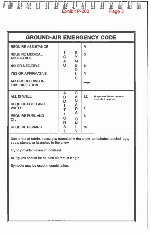
GROUND-AIR EMERGENCY CODE
REQUIRE ASSISTANCE V
REQUIRE MEDICAL I xASSISTANCE C Y
A MNO OR NEGATIVE 0 B N
0YES OR AFFIRMATIVE L Y
SAM PROCEEDING IN —
THIS DIRECTION
A CALL IS WELL D A LL (A space of 10 feet betwoon
Nsymbols if possible)
REQUIRE FOOD AND I AWATER T D F
i AREQUIRE FUEL AND ‘ LOIL 0 o
N NREQUIRE REPAIRS A L W
. L Y
Use strips of fabric, messages trampled in the snow, parachutes, peeled logs,sods, stones, or branches in the snow.
Try to provide maximum contrast.
All figures should be at least 40 feet in length.
Symbols may be used in combination.
Exhibit P-200 Page 3

[ [ 1. r I I I I I I r [ i [, I
Personal Information
NAME:
ADDRESS:
CITY:
___________________
PROVINCE:
_____
POSTAL CODE:
PHONE NOs.
Residence:____________________ Business:
________
Cellular
_____________________
E-mail:
__________
Contact Person
NAME:
_____
ADDRESS:
CITY:
____________
PROVINCE:
_____
POSTAL CODE:
_____________
PHONE NOs.
Residence:_____________________ Business:
________
Cellular
_____________________
E-mail:
__________
PLEASE PRINT ALL INFORMATION
Casara Handbook
Exhibit P-200 Page 4

I 3H1 ibot I I r [ [ I 1 I I I. F I
Training Certification ii
TrainingDate & Location and/or Searches Certified
Completed By:
Exhibit P-200 Page 5

I Cára ILidbLs I F I P 1 F r r r [, r r
Training Certification iii
TrainingDate & Location and/or Searches Certified
Completed By:
Exhibit P-200 Page 6
fl F F F I I I [ [ V I I V [ V
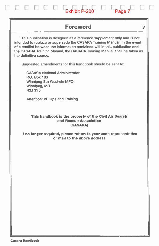
Foreword iv
This publication is designed as a reference supplement only and is notintended to replace or supersede the CASARA Training Manual. In the eventof a conflict between the information contained within this publication andthe CASARA Training Manual, the CASARA Training Manual shall be taken asthe definitive source.
Suggested amendments for this handbook should be sent to:
CASARA National AdministratorP.O. Box 183Winnipeg Stn Westwin MPGWinnipeg, MBR3J 3Y5
Attention: VP Ops and Training
This handbook is the property of the Civil Air Searchand Rescue Association
(CASARA)
If no longer required, please return to your zone representativeor mail to the above address
Casara Handbook
Exhibit P-200 Page 7

Lr [ [ C cr i I I cry F [ V
Table of Contents v
Personal InformationTraining CertificationForeword hiRecord of Amendments ivList of Contents v-vi
1 GENERAL
Mission and Vision Statements 1.0SAP Phone Numbers and SAP Frequencies 1.1Suggested Organization 1.2CASARA Duty Log 1.3Crew Assignment Form 1.4Sighting Information Form 1.5CASARA Navigation Form 1.6Briefing Search Object Information 1.7SAP Mission Briefing Information 1.8Air Debriefing Form 1.9Notice of Crash Location (NOCL) 1.10Canadian Search Area Definition Method (CSAD) 1.11
2 ELECTRONIC SEARCHES
Initial ELT Detection 2.1Initial Track Search (ELT) 2.2ELT Homing - Procedure A (Aural Null) 2.3ELT Homing - Procedure B (Aural Null) 2.4ELT Homing - Using L-Tronics Homer (LH1OA) 2.5ELT Homing - Using L-Tronics Homer (LH1 OA and LA1 OA) 2.6ELT Homing - Using L-Tronics Homer (LL-1 6) 2.7ELT Homing - Using L-Tronics Homer (LL-16) 2.8
3 VISUAL SEARCHES
Heights and Visibility Distances 3.1Visual Searches - Track Crawl 3.2Visual Searches - Creeping Line Ahead (CIA) I Parallel Track 3.3Visual Searches - Expanding Square 3.4Visual Searches - Sector Search 3.5Visual Searches - Contour Search 3.6
4 LOCATION OF SEARCH OBJECT
Steps to Follow 4.1(Notice of Crash Location (NOCL) Message - Form 1.10)
Casara Handbook
Exhibit P-200 Page 8

IDBJIHI Iboi F I r 1 1 F I [ F F F F
Table of Contents (cont) vi
5 SPOTtING
Spotter’s Check List 5.1(Ground/Air Emergency Cods Inside Back Cover)Scanning Procedures 5.2Reporting to Crew 5.3
6 NAVIGATION
Navigation - Pre-Flight 6.1GEOREF System 6.2
7 CHECK LISTS
Pre-Search Check List 7.1On-Search Check List 7.2Post-Search Procedure 7.3Crew Debrief 7.4JRCC/SM/CASARA Search Coordinator 7.5Insurance- General Information 7.6Bingo Time 7.7ELT Requirement for JRCC 7.8First on the Scene Check List 7.9
Exhibit P-200 Page 9
r r [ 1 1 F F V I [ V I F F [ V
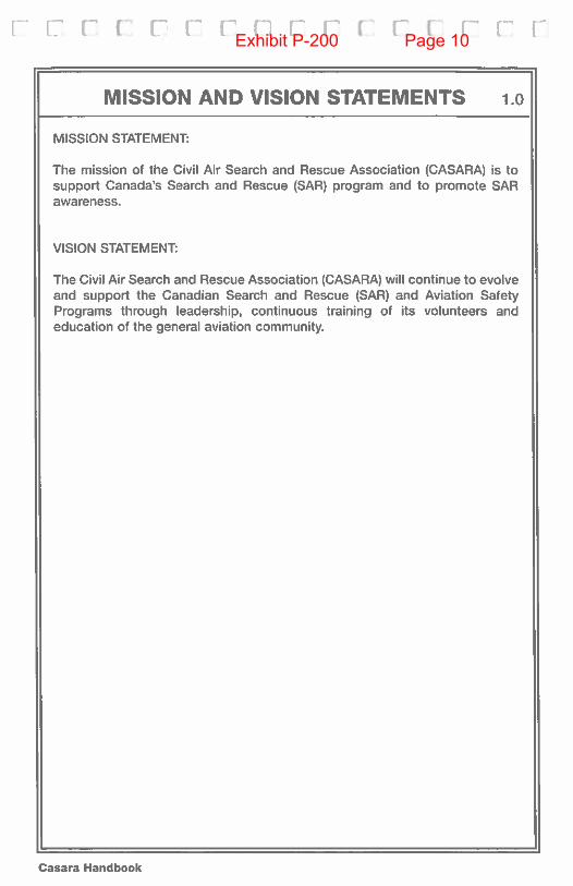
MISSION AND VISION STATEMENTS 1.0
MISSION STATEMENT:
The mission of the Civil Air Search and Rescue Association (CASARA) is tosupport Canada’s Search and Rescue (SAP) program and to promote SARawareness.
VISION STATEMENT:
The Civil Air Search and Rescue Association (CASARA) will continue to evolveand support the Canadian Search and Rescue (SAR) and Aviation SafetyPrograms through leadership, continuous training of its volunteers andeducation ot the general aviation community.
Casara Handbook
Exhibit P-200 Page 10

I F r F I 1 [‘1 rr [ [ F [ F VExhibit P-200 Page 11

r [ F [ r i: F V F F• 1- [ [ r F
I GENERAL
SAR Phone Numbers 1.1
JRCC VICTORIA
JRCC TRENTON
JRCC HALIFAX
SAR FREQUENCIES
250-413-89331-800-567-5111
(Fax) 250-41 [email protected]
613-965-38701 -800-267-7270
(Fax) [email protected]
902-427-21001-800-565-1582
(Fax) [email protected] DISTRESS 2182 kHz...VHF SAR ON SCENE 123.1 MHz...VHF AERONAUTICAL DISTRESS 121.5 MHz...VHF FM MARINE DISTRESS 156.8 (CH 16)...UHF MILITARY DISTRESS 243.0 MHz...VHF CASARA OPERATIONS 123.3 MHz*
where authorized
JRCC & SAR REGIONS
Casara Handbook
Exhibit P-200 Page 12

1as4 Haflo4 C F fl 1 F F [‘ I I F I F
Suggested Organization 1.2
JRCC
SEARCHMASTER (MILITARY)
CASARA SEARCH COORDINATOR
SPOTTER CREW CHIEF PILOT CREW CHIEF
NAVIGATOR CREW CHIEF
SPOTTER CREW CHIEF • Provides to CASARA SEARCH COORDassessment of the spotter requirements forthe following day and continuing operations.
• Prepares a list of spotters assigned to eachmilitary and CASARA aircraft.
• Prepares an up-to-date back-up (call out) listot available spoilers.
• Prepares a schedule and assigns spotters.
NAVIGATOR • Same information, except with navigators.CREW CHIEF • Provides navigators for CASARA aircraft only.
PILOT • Same information except with pilots andCREW CHIEF aircraft.
CASARA • Coordinates with JRCC or Searchmaster,SEARCH matching requirements to available crews andCOORDINATOR aircraft.
• Coordinates with CREW CHIEFS, advisingthem of planned requirements and aidingthem in scheduling these requirements.
Exhibit P-200 Page 13
[ r F F [ F- [ F’ I I’ F’ F F F F F
Casara Handbook
Exhibit P-200 Page 14
I asd Hat rno( I I F F [ [ 1’ r I I F FExhibit P-200 Page 15

r r 17 [ r r r r r r r r
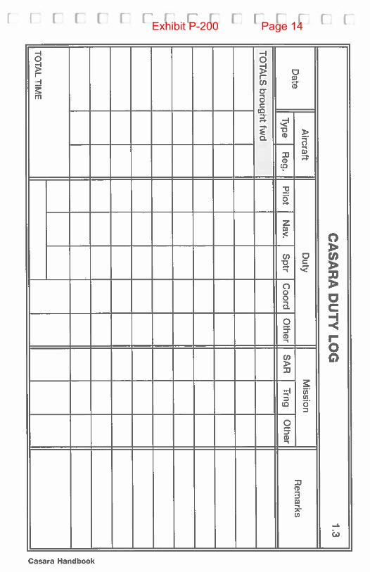
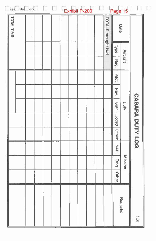
Crew Assignment 1.4
DATE
______________
SAR/TRNG NAME OR NO.________________
AIRCRAFT TYPE
______________-
REG.
PILOT IN COMMAND - -__________
NAVIGATOR
__________________
SENIOR SAR TECH
_____________
SPOTTER (S) 1.
__________________
2. 3.
4.
_________________
5.
SEARCH PAUERN
SEARCH ALTITUDE —
SCANNING RANGE —
SEARCH AREAWEATHER FORECAST
NOTES:
Casara Handbook
Exhibit P-200 Page 16

asHawoL rrrr rr ri u [ r’
Crew Assignment 1.4
DATE
______________________
SAR1RNG NAME OR NO.
________________
AIRCRAFT TYPE
___________________
REG.
PILOT IN COMMAND____________
NAVIGATOR --_________________
SENIOR SAR TECH
_____________
SPOHER (S) 1.
__________________
2. 3.
4.
_________________
5.
SEARCH PAUERN
SEARCH ALTITUDE —
SCANNING RANGE —
SEARCH AREAWEATHER FORECAST
NOTES:
Exhibit P-200 Page 17

F [ F F F F V V [ [ F [.. F E F
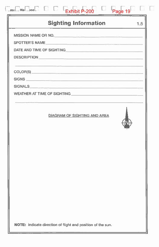
Sighting Information 1.5
MISSION NAME OR NO.__________________
________
SPOTTERS NAME______________________________________
DATE AND TIME OF SIGHTING___________________________
DESCRIPTION
COLOR(S)
SIGNS
__________
SIGNALS_______
WEATHER AT TIME OF SIGHTING
_______________
DIAGRAM OF SIGHTING AND AREA
NOTE: Indicate direction of flight and position of the sun.
Casara Handbook
Exhibit P-200 Page 18
[.as._HaLjooi. I I [ F I [ F’ F F F F F,
Sighting Information 1.5
MISSION NAME OR NO.______________________
SPOTTER’S NAME
___________________________
DATE AND TIME OF SIGHTING___________________
DESCRIPTION -______________________________
COLOR(S)
SIGNS
__________________________________-
SIGNALS___________________________________
WEATHER AT TIME OF SIGHTING
_____________-
DIAGRAM OF SIGHTING AND AREA
NOTE: Indicate direction of flight and position of the sun.
Exhibit P-200 Page 19
CA
SA
RA
NA
VIG
AT
ION
FOR
MExhibit P-200 Page 20

[asdHaf,00l [‘1 i r 1 r ri 1 r ri
BRIEFING SEARCH OBJECT INFORMATION 1.7
DATE SAR NAME[ASKING NUMBER
JRCC CONTROLLERNATURE OF EMERGENCY
SEARCH OBJECT TYPE PHOTO OF TYPE PROVIDED
CALL SIGN/ID.
COLOWFRIM
DISTINCTIVE FEATURE.
DEPARTURE POINT TIME OF DEPARTURE
ROUTE
DESTINATION ETA ETE
LAST KNOWN POINT
ENDURANCE TRUE AIRSPEED
PILOT’S NAME
EXPERIENCE
NUMBER ON BOARD
NAMES OF POB
PERTINENT MEDICAL HISTORY
DISTINCTIVE CLOTHING
OTHER FEATURES
HABITS
PREVIOUS PROBLEMS
SURVIVAL EXPERIENCE
SURVIVAL GEAR
COMMS EQUIPMENT
WEATHERATTIME FREQUENCY -____________________
ELT/EPIRB/PLB TYPE
OTHER SAR NC CALL SIGNS AND AREAS BEING SEARCHED
OTHER INFORMATION
Exhibit P-200 Page 21

r r r 1 r r I I t r r r r c
SEARCH MISSION BRIEFING INFORMATION 1.8
ELT/SIGHTINGS HISTORY:
SEARCH PAHERNS:
ALTITUDENISIBILIW:
SEARCH AREA ASSIGNED:
TRANSIT ALTITUDE/ROUTE/CONFLICTS:
TURNS INSIDE/OUTSIDE AREAS:
COMMS FREQS:
ON SCENE COMMANDER (OSC):
PRESENT WEATHER AND FORECAST:
NEW OBSTRUCTIONS:
NOTAMS:
OTHER SAR RESOURCES:
REPORTING OPS NORM:
DEBRIEFING PROCEDURES:
HOMER CHECKS PRIOR TO TAKE OFF:
ALL NC TO USE “RESCUE” CALLSIGN IN ACTUAL:
RADIO CHECKS PRIOR TO TAKEOFF:
ALL NC TO REPORT “TIME OFF, BINGO, TIME ON/OFF SEARCH:
SYNCHRONIZE WATCHES:
CASARA HANDBOOKS:
SAFETY OFFICER:
NOTES:
Casara Handbook
Exhibit P-200 Page 22
I as4 Ha )oa
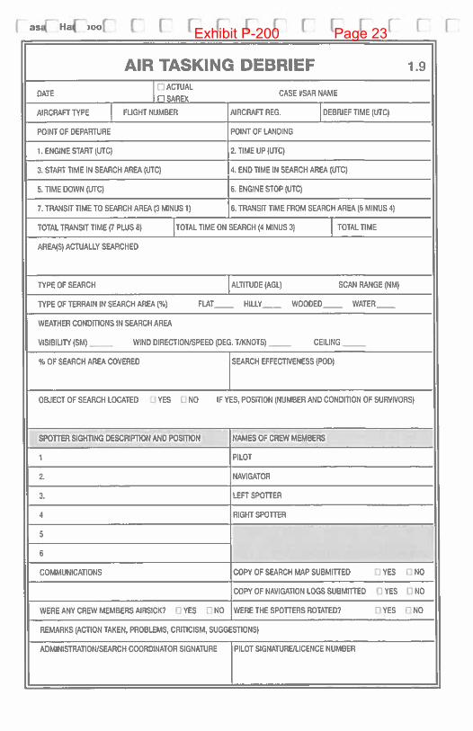
AIR TASKING DEBRIEF 1.9
DATEACTUAL
CASE #SAR NAME
AIRCRAFT TYPE FLIGHT NUMBER AIRCRAFT REG. DEBRIEF TIME (UTC(
POINT OF DEPARTURE POINT OF LANDLNG
1. ENGINE START (UTC) 2. TIME UP (UTC(
3, START TIME IN SEARCH AREA (UTC( 4. END TIME IN SEARCH AREA (UTC)
5. TIME DOWN (UTC( 6. ENGINE STOP (UTC(
7. TRANSIT TIME TD SEARCH AREA (3 MINUS 1) 8. TRANSIT TIME FROM SEARCH AREA (6 MINUS 4)
TOTAL TRANSIT TIME)? PLUS 6) TOTAL TIME ON SEARCH (4 MINUS 3) TOTAL TIME
AREA(S) ACTUALLY SEARCHED
TYPE OF SEARCH ALTITUDE (AGL( SCAN RANOE (NM)
TYPE OF TERRAIN IN SEARCH AREA (%) FLAT HILLY WOODED WATER
WEATHER CONDITIONS IN SEARCH AREA
VISIBILITY (SM) - WIND DIRECTION/SPEED (DEG. T/KNOTS) CEILING
% OF SEARCH AREA COVERED SEARCH EFFECTIVENESS (POD)
OBJECT OF SEARCH LOCATED 0 YES NO IF YES, POSITION (NUMBER AND CONDITION OF SURVIVORS)
SPO1ThR SIGHTING DESCRIPTION AND POSITION NAMES OF CREW MEMBERS
I PILOT
2. NAVIGATOR
3. LEFT SPOTTER
4 RIGHT SPOTTER
: flCOMMUNICATIONS COPY OF SEARCH MAP SUBMITTED 0 YES 0 NO
COPY OF NAVIGATION LOGS SUBMITTED 0 YES 0 NO
WERE ANY CREW MEMBERS AIRSICK? i YES F] NO WERE THE SPOTTERS ROTATED? [1 YES 0 NO
REMARKS (ACTION TAKEN, PROBLEMS, CRITICISM, SUGGESTIONS)
ADMINISTRATION/SEARCH COORDINATOR SIGNATURE PILOT SIGNATURE/LICENCE NUMBER
Exhibit P-200 Page 23
[LII II[ [[[111 II [
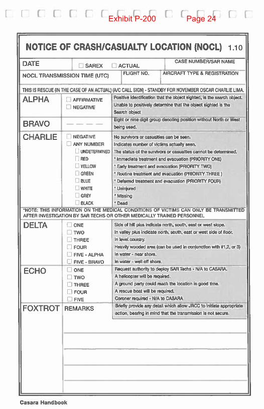
NOTICE OF CRASHICASUALTY LOCATION (NOCL) 1.10
CASE NUMBER/SAR NAMEDATE CSAREX C ACTUAL
NOCL TRANSMISSION TIME (UTC) FLIGHT NO. AIRCRAFT TYPE & REGISTRATION
THIS IS RESCUE (IN THE CASE OF AN ACTUAL) (NC CALL SIGN) - STANDBY FOR NOVEMBER OSCAR CHARLIE LIMA.
ALPHA C AFFIRMATIVE -- Positive identification that the object sighted, is the search object.
0 NEGATIVE Unable to positively determine that the object sighted is the
Search abject
BRAVO— Eight or nine digit grup denoting position without Noyest
CHARLIE C NEGATIVE Na survivors or casualties can be seen.
C ANY NUMBER Indicates number of victims actually seen.
UNDETERMINED The status ot the survivors or casualties cannot be determined.
Q RED • Immediate treatment and evacuation (PRIORITY ONE)
0 YELLOW Eady treatment and evacuation (PRIORITY TWO)
0 GREEN • Routine treatment and evacuation (PRIORITY THREE)
0 BLUE • Deferred treatment and evacuation (PRIORITY FOUR)
0 WHITE Uninjured
0 GREY * Missing
0 BLACK • Dead‘NOTE: THIS INFORMATION ON THE MEDICAL CONDITIONS OF VICTIMS CAN ONLY BE TRANSMITtEDAFTER INVESTIGATION DY SAR TECHS OR OTHER MEDICALLY TRAINED PERSONNEL
DELTA C ONE Side of hill plus Indicate north, south, east or west slope.
C TWO In valley plus indicate north, south, east or west side of floor.
C THREE In level country.
C FOUR Heavily wooded area (can be used in conjunction with #1,2, or 3)
C FIVE - ALPHA In water - near shore.
C FIVE - BRAVO In water - well off shore.
ECHO C ONE Request authority to deploy SAR Techs - N/A to CASARA.
C TWO A helicopter will be required.
C THREE A ground party could reach the location in good time.
C FOUR A rescue boat will be required.
C FIVE Coroner required - N/A to CASARA
FOXTROT REMARKSBriefly provide any detail whIch allow JRCC to initiate appropriate
action, bearing in mind that the transmission is not secure.
Casara Handbook
Exhibit P-200 Page 24

[:as{HJ’boj F I I I I [ [ [ [ [ [ [
CANADIAN SEARCH AREA DEFINITION METHOD (CSAD) 1.11
The use of the Canadian Search Area Definition (CSAD) requires the followinginformation:
1 the last known position (LKP);
2 the intended route; and
3 the intended destination.
The CSAD method applies to all intended track lengths. The two areas are:
I Area One — A rectangle 10 miles each side of track beginning 10 miles before LKPand extending 10 miles beyond destination; and
2 Area TWo — A rectangle 15 miles each side of track beginning at the LKP andextending 15 miles beyond destination. Area Two includes that portion of Area Onewhere overlapping occurs.
AREA ONEA
LKP lo%.i nEST
r AREA TWO
LKP DESTL.. 15NM
Where an enroute turning point includes a track direction change of greater than 20degrees the outside boundary of each area shall be an arc using the turning point ascentre and a radius equal to 10 miles for Area One and 15 miles for Area Two.
Exhibit P-200 Page 25
[_ C- I i r I r 1 1 1 1’ [ F i r [
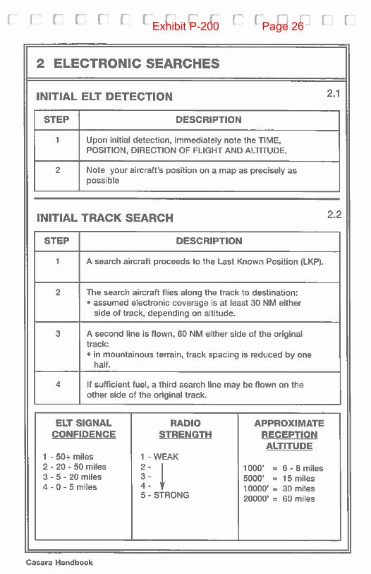
2 ELECTRONIC SEARCHES
INITIAL ELT DETECTION 2.1
STEP DESCRIPTION
2
Upon initial detection, immediately note the TIME,POSITION, DIRECTION OF FLIGHT AND ALTITUDE.
Note your aircraft’s position on a map as precisely aspossible
INITIAL TRACK SEARCH 2.2
STEP DESCRIPTION
1 A search aircraft proceeds to the Last Known Position (LKP).
2 The search aircraft flies along the track to destination:• assumed electronic coverage is at least 30 NM either
side of track, depending on altitude.
3 A second line is flown, 60 NM either side of the originaltrack:• in mountainous terrain, track spacing is reduced by one
half.
4 If sufficient fuel, a third search line may be flown on theother side of the original track.
ELT SIGNALCONFIDENCE
RADIOSTRENGTH
1 - 50+ miles2 - 20 - 50 miles3 - 5 - 20 miles4 - 0 - 5 miles
1 - WEAK
APPROXIMATERECEPTIONALTITUDE
2-3-4-5 - STRONG
1000’5000’10000’20000’
= 6 - 6 miles= 15 miles= 30 miles= 60 mites
Casara Handbook
Exhibit P-200 Page 26
[s(Hbo4 [[11[[[[[[[[2.3
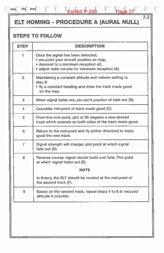
ELT HOMING - PROCEDURE A (AURAL NULL)
STEPS TO FOLLOW
STEP DESCRIPTION
1 Once the signal has been detected;• pin-point your aircraft position on map,• descend to a minimum reception alt,• adjust radio volume for minimum reception (A).
2 Maintaining a constant altitude and volume setting tostep 8;• fly a constant heading and draw the track made good
on the map.
3 When signal fades out, pin-point position of fade-out (B).
4 Calculate mid-point of track made good (C).
5 From this mid-point, plot at 90 degrees a new desiredtrack which extends on both sides of the track made good.
6. Return to the mid-point and fly (either direction) to makegood the new track.
7 Signal strength will change; plot point at which signalfads out (D).
S Reverse course: signal should build and fade. Plot pointat which signal fades out (E).
NOTE
In theory, the ELT should be located at the mid-point ofthe second track (9.
9 Based on the second track, repeat steps 4 to 8 at reducedaltitude if possible.
Exhibit P-200 Page 27

n I r r r r r r
2.3ELT HOMING - PROCEDURE A (AURAL NULL)(cont)
COMMENT
Repeating the procedure at a tower altitude may reduce the area in which theELT is located sufficiently to permit a visual search, using an expandingsquare or sector search.
ILLUSTRATION
NOTE
BExtreme Radiusof Signal
Accurate navigation is necessary for the Aural Null procedure to be effective.
0
A
ELTLocation
E
Casara Handbook
Exhibit P-200 Page 28
[:as4Habo4 [ [IL Ft EF’[ I [1 F2.4
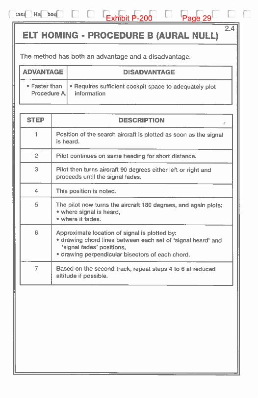
ELT HOMING - PROCEDURE B (AURAL NULL)
The method has both an advantage and a disadvantage.
ADVANTAGE DISADVANTAGE
• Faster than • Requires sufficient cockpit space to adequately plotProcedure A. information
STEP DESCRIPTION
1 Position of the search aircraft is plotted as soon as the signalis heard.
2 Pilot continues on same heading for short distance.
3 Pilot then turns aircraft 90 degrees either left or right andproceeds until the signal fades.
4 This position is noted.
5 The pilot now turns the aircraft 180 degrees, and again plots:• where signal is heard,• where it fades.
6 Approximate location of signal is plotted by:• drawing chord lines between each set of ‘signal heard’ and
‘signal fades’ positions,• drawing perpendicular bisectors of each chord.
7 Based on the second track, repeat steps 4 to 6 at reducedaltitude if possible.
Exhibit P-200 Page 29

I i i r r r r [ F__ F [ [
2.4ELT HOMING - PROCEDURE B (AURAL NULL)(cont)
STEP DESCRIPTION
8 Aircraft proceeds to the point at which all three perpendicularsintersect, and descends to a level appropriate for sighting.
Extreme Radiusof Signal
NOTE
Accurate navigation is necessary for the Aural Null procedure to be effective.
Casara Handbook
Exhibit P-200 Page 30

r ,as Ha. boa [ F F F F [] r r [• r— F”
ELT HOMING - USING L-TRONICS HOMER (LHIOA)
Set frequency, REC mode, SENS minimum, VOL at 12 o’clock.
In this mode the meter reads signal strength, left (weaker) toright (stronger).
Turn SENS up until the meter goes up scale and the signal isaudible.
Turn in a circle until the needle goes furthest upscale. In thisposition, the arrow on left ann of the antenna assembly will bepointing at the signal source.
Without changing controls, turn antenna until horizontal withthe ground. A noticeable increase in signal strength meanstransmitter is horizontal. Use special antenna assemblyshown in manual.
As volume increases and/or needle nears right-hand stop,decrease SENS.
The closer to target, the more rapidly volume and sensitivityincrease.
To elevate quality of bearing, turn a full circle. If multiplereading of about equal upscale movements results, move toanother location.
MIN MAX
2.5
GROUND OPERATION IN THE SIGNAL STRENGTH MODE
Use ground antenna only.
Exhibit P-200 Page 31

c: r i [‘ r r r r t r c r r r
2.6ELT HOMING -
USING L-TRONICS HOMER (LHIOA AND LA1OA)
GROUND AND AIR OPERATION IN THE LEFT-RIGHTHOMING MODE
1 Use either aircraft or ground antenna.
2 Set frequency, DF mode, SENS minimum, VOL at 12 o’clock
3 Turn SENS up until meter needle goes left or right and signalis audible.
4 Turn toward needle until it centers. You are facing the target.
5 Left to right needle swing is normal when walking, driving orflying. Follow headings that keep left and right swings aboutequal.
6 As volume increases and/or needle gets too sensitive,decrease SENS. Slight left-right swing and audible signal isenough.
7 The closer to target, the more rapidly volume and sensitivityincrease.
8 To evaluate the quality of the bearing, turn a full circle. If theneedle centers more than twice 180 degrees apart, move toanother location or fly a circle, keeping needle either left orright with a constant indication.
NTURN LEFT
L/TURN RIGHT
Casara Handbook
Exhibit P-200 Page 32
r- r r r r r r ri - —
as H boc [ I I I I I I L
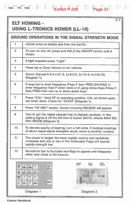
2.7ELT HOMING -
USING L-TRONICS HOMER (LL-16)
GROUND OPERATIONS IN THE SIGNAL STRENGTH MODE
1 Unfold antenna blades and then the handle.
2 To turn on and off, press and HOLD the ON/OFF button until itbeeps.
3 If light required press “Light”.
4 Press Up or Down Arrows to set volume.
5 Select channel 0-9 (1=121.5, 2=243.0, 3=121.6, 4=123.10)(Diagram 1).
6 If required to enter frequency Press F then FREQ (KEYPAD 1)enter frequency then F when done or if using Arrow Keys Press Fthen FREO then use up or down arrow keys.
7 Press CAL”. Hold OF in operating position. CAL on screen goesout when done. Check for “COOD (Diagram 1).
8 Press “DF-REC” button. Screen showing RECEIVE will appear.
9 Turn to get the tallest strength bar or highest numbers. In thissetting signal is off the left end of homer (NOTE: Arrows MAX SICREC MODE) (Diagram 2).
10 To elevate quality of bearing, turn a full circle. If multiple readingsof about equal signal strengths result, move to another location.
11 The closer to target, the more rapidly volume and sensitivityincreases and one or two of the Attenuator Flags will appearbeside strength bar.
12 Normal for bar to fluctuate and flags to appear and disappearwhen very close to the beacon.
FORE EXT LEFTI 2 3 AFT PWR RiGHT
I I FaEc rzci
I 4 5 6 Cr1?. OOW SETI Sf12 SETS !.P- ND
REC 8’ 9] J330 E LIVE
CAL0 ioc FuGMI IT jam
Diagram 1 Diagram 2
Casara Handbook
Exhibit P-200 Page 33
cisridndlik[ F inn F r
2.8
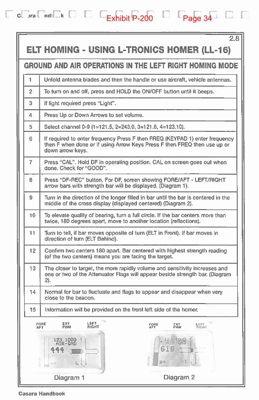
ELT HOMING - USING L-TRONICS HOMER (LL-16)
GROUND AND AIR OPERATIONS IN THE LEFT RIGHT HOMING MODE
1 Unfold antenna blades and then the handle or use aircraft, vehicle antennas.
2 To turn on and off, press and HOLD the ON/OFF button until it beeps.
3 If light required press “Light”.
4 Press Up or Down Arrows to set volume.
5 Select channel 0-9 (1=121.5, 2=243.0, 3=121.6, 4=123.10).
6 If required to enter frequency Press F then FREQ (KEYPAD 1) enter frequencythen F when done or if using Arrow Keys Press F then FREQ then use up ordown arrow keys.
7 Press ‘CAL”. Hold DF in operating position. CAL on screen goes out whendone. Check for “GOOD”.
8 Press “DF-REC” button. For DF, screen showing FORE/AFT - LEFT/RIGHTarrow bars with strength bar will be displayed. (Diagram 1).
9 Turn in the direction of the longer filled in bar until the bar is centered in themiddle of the cross display (displayed centered) (Diagram 2).
10 To elevate quality of bearing, turn a full circle. If the bar centers more thantwice, 180 degrees apart, move to another location (reflections).
11 Turn to tell, if bar moves opposite of turn (ELT in Front). If bar moves indirection of turn (ELT Behind).
12 Confirm two centers 180 apart. Bar centered with highest strength reading(of the two centers) means you are facing the target.
13 The closer to target, the more rapidly volume and sensitivity increases andone or two of the Aftenuator Flags will appear beside strength bar. (Diagram2).
14 Normal for bar to fluctuate and flags to appear and disappear when veryclose to the beacon.
15 Information will be provided on the front left side of the homer.
FORE EXT LEFT FORE EXT LEFTAFT PWR RIGHT AFT PWR RIGHT
rttL1Diagram 1 Diagram 2
Casara Handbook
Exhibit P-200 Page 34
FasIjHiboA IE[ [[[[F_Fl [F [
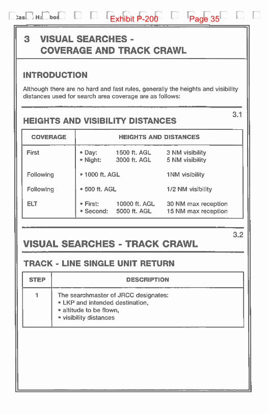
3 VISUAL SEARCHES -
COVERAGE AND TRACK CRAWL
INTRODUCTION
Although there are no hard and fast rules, generally the heights and visibilitydistances used for search area coverage are as follows:
3.1HEIGHTS AND VISIBILITY DISTANCES
COVERAGE HEIGHTS AND DISTANCES
First • Day: 1500ft. AOL 3 NM visibility• Night: 3000 ft. AOL 5 NM visibility
Following • 1000 ft. AOL 1 NM visibility
Following • 500 ft. AOL 1/2 NM visibility
ELT • First: 10000 ft. AOL 30 NM max reception• Second: 5000 ft. AOL 15 NM max reception
3.2VISUAL SEARCHES - TRACK CRAWL
TRACK - LINE SINGLE UNIT RETURN
STEP DESCRIPTION
1 The searchmaster of JRCC designates:• LKP and intended destination,• altitude to be flown,• visibility distances
Exhibit P-200 Page 35
C- r: F I rn r: F [ I I 1: 1; [ r
VISUAL SEARCHES- 3.2
TRACK CRAWL (cont)
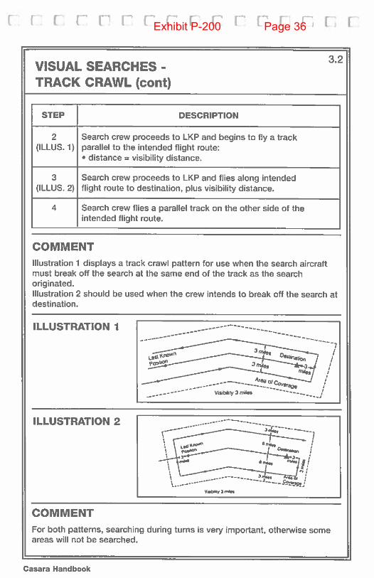
STEP DESCRIPTION
2(ILLUS. 1)
3(ILLUS. 2)
4
Search crew proceeds to LKP and begins to fly a trackparallel to the intended flight route:• distance = visibility distance.
Search crew proceeds to LKP and flies along intendedflight route to destination, plus visibility distance.
Search crew flies a parallel track on the other side of theintended flight route.
COMMENT
Illustration 1 displays a track crawl pattern for use when the search aircraftmust break off the search at the same end of the track as the searchoriginated.Illustration 2 should be used when the crew intends to break off the search atdestination.
ILLUSTRATION I
ILLUSTRATION 2
COMMENT
For both patterns, searching during turnsareas will not be searched.
is very important, otherwise some
vsy an_s
Casara Handbook
Exhibit P-200 Page 36

[ Ca 3 Hr Iboj [ [1 [ 1 1 [ 1 V 1 [ 1 V
VISUAL SEARCHES-
CREEPING LINE AHEAD (CLA)/PARALLEL TRACK
These are two types of patterns which require successive search legsadvancing across a search area. They are Creeping Line or Parallel Trackpatterns. Both are employed to provide uniform coverage over areas whereonly the approximate position of the target can be estimated. Such patternsare called Creeping Line when the legs are parallel to the shortest side of thesearch area.
Width
CREEPING LINE PATTERNCreeping Line patterns are suitable for rapid advancement along a giventrack or drift line.
A Parallel Track differs from a Creeping Line in that the legs are parallel to thelongest side of the search area.
PARALLEL TRACK
—
—
S
::zzzzziZzz:i:tParallel track patterns are more suitable for large areas since there are fewerturns and navigation is normally more accurate
Exhibit P-200 Page 37

c: r r [1 r r r r r i [ i:- L r r
VISUAL SEARCHES-
EXPANDING SQUARE
EXPANDING SQUARE SEARCH
STEP PROCEDURE
1 The searchmaster or JRCC designates:• LKP,• altitude to be flown,• visibility distance.• extension of search area.
2 Search crow proceeds to CSR
3 Fly lines at right angles to each other with a track spacing oftwo visibility distance(s), increasing by twice the visibilitydistance on completion of two lines.
4 For second coverage, rotate the search pattern 45 degreesleft or right.
COMMENT
For accuracy, assess the drift and apply corrections before the search starts.For simplicity, fly the cardinal headings. Accurate navigation is extremelyimportant for searches utilizing the expanding square search method.Searching while the aircraft turns is necessary. Each crew should decidewhich way they wish to make their turns, left or right.
ILLUSTRATION
8V
CommenceSearch Paint(CSPI
Last KnownPosition (LKP)
V = Visibility Distance
Casara Handbook
Exhibit P-200 Page 38

ca4aHjjboI ni inn F V[ r rr
VISUAL SEARCHES-
SECTOR SEARCH
The sector search is used when the last known position (LKP) is establishedwith a high degree of accuracy and the search area is relatively small.
The sector search could be used:
• when persons are lost in bushland and their whereabouts established in asmall area,
• on completion of an Emergency Locator Transmitter (ELT) or PersonalLocator Beacon (PLB) homing when the source of the signal cannot bereadily seen.
STEP PROCEDURE
1 The searchmaster or JRCC designates:• LKP,• altitude to be flown,• visibility distances.
2 Search crew proceeds to Commence Search Point (CSP) orLKR
3 Fly lines radiating from the center every 60 degrees.
4 For second coverage rotate the search pattern 30 degreesleft or right.
Exhibit P-200 Page 39

H r F r (1 r r r r r i r r [. r
3.5VISUAL SEARCHES -
SECTOR SEARCH (cont)
Angular displacement ofLong legs still the same
End of first search.Aircraft proceeds on offsetof 30 degrees and begins again
Commence SearchPoint (CSP)Start 1st search
Normally, sector search patterns should not have a radius greater than 10nautical miles (M) for aircraft or 5 M for vessels; another type of patternshould be used for search areas any larger than 300 square miles. Usually asix sector pattern is used, simplifying the navigation in that each turn is 120degrees to the right. If a second pattern is required, it is commenced 30degrees off the first.
Casara Handbook
Exhibit P-200 Page 40

[ aJ iHJ IDol 1 1 1 1 1 1 [ F [ F F I
VISUAL SEARCHES- 3.6
CONTOUR SEARCH
ASSESSING THE AREA
STEP PROCEDURE DESCRIPTION
1 Plot the area • receive assigned area and mark onmap
2 Study the • look for heights, orientation of ridgetopography lines, local air strips, contour
gradients, glaciers
3 Check the • check present and forecastweather weather
4 Proceed to • look for signs of strong winds orarea turbulence
5 Check out the • cross area 1 000 ft. above highestarea peak
• check the weather• confirm relationship of map to ground
6 Plan your • note all prominent featuressearch • plot escape mutes
COMMENT
The instruction here assumes an assigned altitude of 500 ft. and a scanningrange of 1/2 mile
FLYING THE CONTOUR
STEP PROCEDURE
1 Fly across the peak at 500 ft. AOL to allow good inspectionof the summit
2 Note the altitude.
Exhibit P-200 Page 41

r r r r r r r r r r r r ri. [ [
VISUAL SEARCHES -
CONTOUR SEARCH (cont)
FLYING THE CONTOUR (cont)
STEP PROCEDURE
3
4
5
Fly away from the mountain and make a descending turnto arrive at the same location, flying the opposite direction,500 ft. lower.
Fly the altitude “hugging” the mountain.
Turn away and repeat steps 3 and 4 as required.
ILLUSTRATION -
FLYING THE CONTOUR
NOTE
Pawns wi Iq*n w,th ‘WI 0 ngN hand ara band 01áaaft rnqti.r..0i slid ma I&,aI Ia ba sw,ad
——
Do nod tinbs& ac‘a. ata aMa
3.6
Casara Handbook
Exhibit P-200 Page 42

[Da&iH(o [ ri r [ ri iii F rVISUAL SEARCHES
- 3.6
CONTOUR SEARCH (cont)
TIPS REGARDING CONTOUR SEARCHES
TIP DESCRIPTION
1 Check the weather for the area - select best route andalternate or cancel out.
2 Keep your aircraft as light as possible.
3 Avoid areas of turbulence.
4 Keep your airspeed up in areas of downdrafts.
5 Stay away from whiteout conditions.
6 Never fly into a valley that is too narrow to permit a180 degree turn at your altitude.
7 Be aware of the effect of temperature on true altitude whentemperature is below ISA.
B Always have a planned emergency exit route.
9 In valleys, fly the right-hand rule.
10 Always be prepared to do 180 degree turn.
11 Be aware of the cable spans.
12 Never fly “UP” valleys.
CHECK LIST: HAVE YOUchecked the weather and terrain along your intended flight route?checked the weather and terrain along your alternate routes?identified an escape route at every point?identified safe altitudes for entering valleys?identified places where you might need to make sharp turns?identified possible areas of high velocity valley winds?allowed for greater turning radius and shallower climbs gradient?
Exhibit P-200 Page 43

1* r r r r’ r r r r r r r fl r r
4 LOCATION OF SEARCH OBJECT
4.1STEPS TO FOLLOW
STEP DESCRIPTION
1 Contact JRCC/searchmaster/CASARA search coordinatoror military aircraft;• for aircraft, use frequency provided by searchmaster in
preflight briefing• relay through nearest FSS or ATC unit.
2 Provide the following information using NOCL message(Form 1 .10):• track,• your aircraft identification,• nature of the sighting,• position and time of sighting,• available information about survivors,• how long you can remain on scene before diverting for
fuel,• any other pertinent information.
3 Request an ETA for on-scene of SAR aircraft, and transitaltitude;• if you can, hold an altitude higher than SAR transiting
aircraft to provide a homing target.
4 Provide whatever assistance you are able to give whenrequested.
5 All other aircraft remain on assigned task.
Casara Handbook
Exhibit P-200 Page 44

Ea54H400( [[ [ fr[
f[ [1 [ [ [
5 SPOTTING
5.1SPOTTER’S CHECK LIST
• PILOTS should ensure that spotters are thoroughly briefed on thefollowing:
OBJECT OF SEARCH • Aircraft - Vessel Person• Colour, Registration• Last known position• Number of persons• Signals available (ELT, EPIRB-PLB)
TYPE OF SEARCH
EXPECTED TERRAIN IN SEARCH AREA
EXPECTED WEATHER IN SEARCH AREA
SCANNING PROCEDURES
SPOHER ROTATION SCHEDULE
INTERCOM USE
EMERGENCY PROCEDURES IN EVENT OF FORCED LANDING (includingsurvival gear on board and ELT location and operating procedure.)
PLANNED STOPS (OVERNIGHT, LUNCH)
DRESS FOR OUTSIDE ENVIRONMENT
CLOCK PROCEDURE OF PILOT NOTIFICATION IF SEARCH OBJECTSIGHTED
PENCIL AND PAPER FOR SIGHTING DIAGRAM
NOTE
Ground to air emergency code on inside back cover.
Exhibit P-200 Page 45
F r• t 1’ [1 [ r [1 f r F I L H C] C
SCANNING PROCEDURES5.2
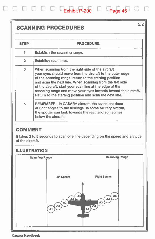
STEP PROCEDURE
1 Establish the scanning range.
2 Establish scan lines.
3 When scanning from the right side of the aircraftyour eyes should move from the aircraft to the outer edgeof the scanning range, return to the starting positionand scan the next line. When scanning from the left sideof the aircraft, start your scan line at the edge of thescanning range and move your eyes inwards toward the aircraft.Return to the starling position and scan the next line.
4 REMEMBER - in CASARA aircraft, the scans are doneat right angles to the fuselage. In some military aircraft,the spotter can look towards the rear, and sometimesbelow the aircraft.
COMMENT
It takes 2 to 8 seconds to scan one line depending on the speed and altitudeof the aircraft.
ILLUSTRATION
Casara Handbook
Exhibit P-200 Page 46
as Ha i0o! [ I F C I: [ I [ F r F [
REPORTING TO CREW
SEARCH OBJECT SPOrTED
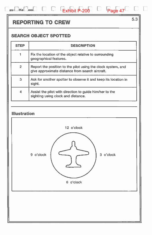
STEP DESCRIPTION
1 Fix the location of the object relative to surroundinggeographical features.
2 Report the position to the pilot using the clock system. andgive approximate distance from search aircraft.
3 Ask for another spotter to observe it and keep its location insight.
4 Assist the pilot with direction to guide him/her to thesighting using clock and distance.
Illustration
12 o’clock
9 o’clock 3 o’clock
6 o’clock
5.3
Exhibit P-200 Page 47

r 1: [ r [ F I ( I [• 1 I- [ H I [
6 NAVIGATION
6.1NAVIGATOR DUTIES
STEP DESCRIPTION
1 Study your map.
2 Envisage your intended mission:• from point of departure,• through the search operation,• to your return to the aerodrome.
3 Assess the features that will help you to navigate.
4 Calculate the time at which you will have to break off theflight so as to return with a safe fuel reserve. Verify thisreserve with the aircraft commander.
5 Calculate the distances from check-point to check-point.
6 Prepare a map of your search assignment. Accuratemap preparation is the cornerstone of an effective search.
7 Maintain an accurate log of all flight activity (see 1.6).Record NOCL information. Show to whom and timesent.
GEOREF SYSTEM6.2
DESCRIPTION
Every 1:500 000 scale aeronautical map is as follows:
• rectangles of one degree of latitude and one degree of longitude,• identified by a two-letter symbol, printed in purple on the lower left corner
of latitude,• each rectangle is divided into four smaller rectangles of 30 mm of longitude
by 30 mm of latitude,• identified by numbers 1 to 4, starting at the upper left corner and going
from left to right. The numbers are not printed on map,• these small rectangles are subdivided into four sub-areas measuring 15
mm of longitude by 15 mm of latitude,• identified by letters a, b, c, d in same sequence as above. The letters are
not printed on map.
Casara Handbook
Exhibit P-200 Page 48

as Hal ioo U r i• I [ F [ [ F [: I
GEOREF SYSTEM - ILLUSTRATION6.2
SEARCH AREA IDENTIFICATION USING GEOREF
STEPS TO FOLLOW
STEP DESCRIPTION
1 Rough in the boundaries of your area in pencil. Note theNC call-signs allocated to adjacent areas.
2 Study the area looking for terrain features and determinewhich search procedure would be best.
3 Plan flight path lines to be into wind to best eliminatedrift.
4 Draw search lines on your map.
5 Survey the lines looking for check-points.
6 Check the height of the terrain, add it to the intended searchaltitude, and write it down near the start of the first line.
7 Pick an altitude for transiting to search area, considering:terrain, traffic.
52dh
2
0I
3 4
5I 30
Ti_fl CF
cdjcd.-4-t-4--.ab:a b—-—4.—_4_—
cjd
CF
8I
F—i
Exhibit P-200 Page 49

E r F I r i i 1 1 I I F F [ F. [
7 CHECK LISTS
7.1PRE-SEARCH CHECK LIST
The pilot-in-command should complete the following before commencingsearch:
A. ONCE AIRBORNE - CONTACT JRCC/SM OR CASARA SEARCHCOORDINATOR AND ADVISE TIME OFF AND ETA FOR COMMENCESEARCH POINT.
B. MONITOR VHF EMERGENCY FREQUENCIES AND FREQUENCIESWHICH MAY BE USED BY THE MISSING CRAFT, AND BE ALERT FORBOTH MODULATED AND UNMODULATED SIGNALS.
C. MAINTAIN LOG TO ENSURE A COMPLETE RESUME OF ALL ACTIVITIESARE AVAILABLE FOR DEBRIEFING.
D. ARRIVE AT ASSIGNED STARTING POINT TO ENABLE AIRCRAFT TO BEESTABLISHED ON INITIAL SEARCH TRACK BEFORE REACHINGCOMMENCE SEARCH POINT (CSP).
E. ASSIGN SPOTTERS SCHEDULE IN WINDOWS.
F. ASSIGN SPOTTER SCANNING DISTANCE.
G. INTERCOM CHECK OR INTERCREW COMMUNICATION SIGNALS.
H. PRE-SEARCH BRIEFING COMPLETE.
I. AIRSPEED - SEARCH SPEED.
J. SPOTTERS - READY.
K. FLAPS - SET FOR SEARCH SPEED.
L. STALL SPEED - CALCULATED FOR SEARCH CONFIGURATION.
M. HOMING EQUIPMENT - SELECTED.
N. RADIO ALTIMETER - SET SEARCH ALTITUDE.
0. FUEL - SUFFICIENT FOR PLANNED MISSION.
P. LANDING LIGHT ON.
Casara Handbook
Exhibit P-200 Page 50
[asdHarrno1[ff[[IE[[[[[[
7.2ON-SEARCH CHECK LIST
A. CALL JRCC/SM OR CASARA SEARCH COORDINATOR AT COMMENCESEARCH POINT.
B. ALTITUDE- ASSIGNED SEARCH ALTITUDE.
C. SPOTTERS - IN POSITION - COMMENCING TO SEARCH.
D. CONTACT JRCC/SM OR CASARA SEARCH COORDINATOR HOURLYON THE HOUR, OR AS REQUIRED, FOR “OPS NORMAL” STATING:• POSITION,• WEATHER• FUEL IN HOURS AND MINUTES, EXCLUDING RESERVES.
E. WEATHER CHECKS - SEARCH AREA, DESTINATION, ALTERNATE.
F. FUEL - TO ALTERNATE.
G. TIME - UPDATE ESTIMATE OF TIME TO LEAVE SEARCH AREA.
H. MONITOR SPOTrER ROTATION SCHEDULE AND ENSURE SPOTtERSARE RESTING DURING BREAKS.
I. LOG - ALL SIGHTINGS, UNSEARCHED AREAS, WEATHER CONDITIONS(ie- Location of fog banks, etc.) (use Form 1.5).
POST-SEARCH PROCEDURE fl
A. ADVISE CREW OF DEPARTURE FROM SEARCH AREA.
B. ADVISE JRCC/SM OR CASARA SEARCH COORDINATOR OFDEPARTURE FROM SEARCH AREA.
C. ON LANDING - DEBRIEF WITH CREW, THEN:• DEBRIEF WITH JRCC/SM OR CASARA SEARCH COORDINATOR.
Exhibit P-200 Page 51

Hr rr 1 [1 fir r r r r [,ri[
7.4CREW DEBRIEF
A. COMPUTE SEARCH TIME.
B. COMPUTE TRANSIT TIME.
C. ASSESS SEARCH EFFECTIVENESS.
D. DETERMINE PERCENT OF SEARCH AREA COVERED.
E. ASSESS CREW AVAILABILITY FOR SUBSEQUENT TASKINGS -
PASS TO CREW CHIEFS.
F. ENSURE MAP MARKED WITH AIRCRAFT DENT, CREW NAMES,AND DATE/TIME. (Sighting Information - See Form 1.5).
C. QUESTIONS?
NOTE
Obtain record of fuel cost for later reimbursement..
JRCC I SM I CASARA SEARCH COORDINATOR 7.5
Provide the following:
A. LOG OF SIGHTINGS.(Sighting Information - See Form 1.5)
B. DIAGRAM OF SIGHTINGS.
C. SEARCH TIME.
D. TRANSIT TIME.
E. TYPE OF SEARCH CARRIED OUT.
F. SEARCH EFFECTIVENESS.
C. UNSEARCHED AREAS.
H. WEATHER CONDITIONS (SHOWN ON MAP) BOTH HAZARDOUS TOAVIATION AND PERTINENT TO SEARCH.
I. ALSO PROVIDE YOUR MAP WITH ALL THESE DEBRIEF POINTSWRITTEN ON IT FOR LATER REFERENCE.
Casara Handbook
Exhibit P-200 Page 52

[asHa,ooflf[f[[f[[[[1[
7.6INSURANCE - GENERAL INFORMATION
The CASARA National Organization maintains insurance for the followingpurposes;
a. Aircraft Hull and Liability Insurance.(The above insurance is purchased as secondary insurance and isintended to supplement the owner’s private insurance.)
b. Premises, Property and Operations Uability Insurance.
c. Personal Accident Insurance.
d. General Liability and Miscellaneous Articles Floater.
A copy of all policies has been forwarded to each Director. Refer to theindividual policy for specific limits and exclusions.
In all cases of claims or probable claims, the incident must be reported to thefollowing ASAP;
a. Provfferr Director and Zone Commander.
b. If SAR 0p . to SM and/or JRCC.
c. The private insurer of the volunteer aircraft.
d. CASARA Insurance agent: Brian Julien403-735-2424 (office)403-735-2396 (fax)
e. CASARA Administrator: 204-953-2290204-953-2293 (fax)
Use the fastest means of communication.
Provide nature, cause and extent of damage and injury, with identification ofpersons involved and names of witnesses, if possible.
Cooperate with involved third parties and exchange names and addresses, aswell as render aid if required..
THERE IS NO HULL INSURANCE COVERAGE WITH RESPECT TOULTRALIGHT AIRCRAFT, EXPERIMENTAL AIRCRAFT, ROTARY WINGAIRCRAFT OR MILITARY AIRCRAFT
UNDER NO CIRCUMSTANCES ADMIT LIABILITY.
Exhibit P-200 Page 53
r c r i r r r r r r [ r r r; F I
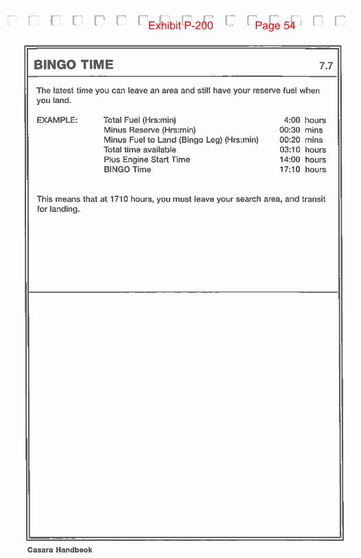
BINGO TIME 7.7
The latest time you can leave an area and still have your reserve fuel whenyou land.
EXAMPLE: Total Fuel (Hrs:min) 4:00 hoursMinus Reserve (Hrs:min) 00:30 minsMinus Fuel to Land (Bingo Leg) (Hrs:min) 00:20 minsTotal time available 03:10 hoursPlus Engine Start Time 14:00 hoursBINGO Time 17:10 hours
This means that at 1710 hours, you must leave your search area, and transitfor landing.
Casara Handbook
Exhibit P-200 Page 54
i r r-, r r r-’ r r r r,as Hairnoti L I L I I IJ
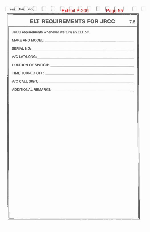
ELT REQUIREMENTS FOR JRCC 7.8
JRCC requirements whenever we turn an ELT off.
MAKE AND MODEL:
__________________
SERIAL NO:
_________________________
NC LAT/LONG:_______________________
POSITION OF SWITCH:
_________________
TIME TURNED OFF:
___________________
NC CALL SIGN: -_____________________
ADDITIONAL REMARKS:
-________________
Exhibit P-200 Page 55
[ V [ [ 13 1 1 C F F I F I [ F V
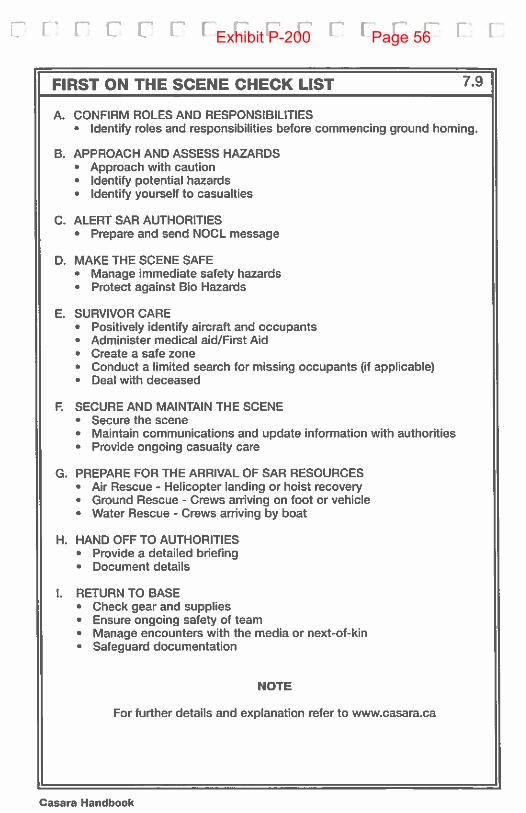
FIRST ON THE SCENE CHECK LIST 7.9
A. CONFIRM ROLES AND RESPONSIBILITIES• Identify roles and responsibilities before commencing ground homing.
B. APPROACH AND ASSESS HAZARDS• Approach with caution• Identify potential hazards• Identify yourself to casualties
C. ALERT SAR AUTHORITIES• Prepare and send NOCL message
D. MAKE THE SCENE SAFE• Manage immediate safety hazards• Protect against Bio Hazards
E. SURVIVOR CARE• Positively identify aircraft and occupants• Administer medical aid/First Aid• Create a safe zone• Conduct a limited search for missing occupants (if applicable)• Deal with deceased
F. SECURE AND MAINTAIN THE SCENE• Secure the scene• Maintain communications and update information with authorities• Provide ongoing casualty care
G. PREPARE FOR THE ARRIVAL OF SAR RESOURCES• Air Rescue - Helicopter landing or hoist recovery• Ground Rescue - Crews arriving on foot or vehicle• Water Rescue - Crews arriving by boat
H. HAND OFF TO AUTHORITIES• Provide a detailed briefing• Document details
I. RETURN TO BASE• Check gear and supplies• Ensure ongoing safety of team• Manage encounters with the media or next-of-kin• Safeguard documentation
NOTE
For further details and explanation refer to www.casara.ca
Casara Handbook
Exhibit P-200 Page 56

[ 1 I I’ I I F I I I [ I r F [ [1Exhibit P-200 Page 57

n r r r r r r r I i r r r r rExhibit P-200 Page 58

i r r F r I F F F’ F [ [ F [ i:Exhibit P-200 Page 59

[ 1’ [‘ F i: c•’ 1’ r [ r 1 F r [ F [Exhibit P-200 Page 60

[ [ F I I [ r [ [ 1 F’ [ r r rExhibit P-200 Page 61

[1 r r r r r r r r r i r r r rExhibit P-200 Page 62

H [ I I I [ r r r r r r r r r HExhibit P-200 Page 63

[ rr [ F 1 1 [ r U F [ F I ( IExhibit P-200 Page 64

[ I [ 1 F I r r I— I [ r r r nExhibit P-200 Page 65

r r r r r r r r i [ i r r rExhibit P-200 Page 66

rrr’r r rr I I ri LE[ IExhibit P-200 Page 67