expandable computer power storage systemblackouts. team 6 was tasked with developing a power storage...
TRANSCRIPT

1
Expandable Computer Power Storage
System
ECE 480 – Michigan State University
Design Team 6 Alan Everdeen, Leon Liang, Tommy MacBeth, Tim Wang

2
Executive Summary The power grid in India is very unreliable, leading to almost daily blackouts that
prevent the consistent use of some electrical devices. Currently there is no way,
besides the use of generators, to keep a computer lab up and running during these
blackouts. Team 6 was tasked with developing a power storage system that would be
able to power a computer lab consisting of a variable number of laptops for five hours at
a time. This system must be powered by solar energy and have a microcontroller-based
battery monitor that displays the remaining charge in the battery bank.
The team was able to successfully design a system that is capable of powering
multiple laptops for long periods of time using lead-acid deep-cycle batteries and a solar
panel array. The status of the battery is displayed on an LCD by means of a
microcontroller. The team’s design is also expandable through the addition of more
deep-cycle batteries and laptop power plugs.

3
Acknowledgements Team 6 would like to thank the following people for their help and support this semester:
Stephen Blosser – For assembling the frames for the solar panels and for being consistently available to answer questions Dr. Robert Mcgough – For his help and direction during the semester Gregg Mulder – For his advice on the design and for supplying the deep-cycle battery
4
Table of Contents Executive Summary ........................................................................................................ 2
Acknowledgements ......................................................................................................... 3
Table of Contents ............................................................................................................ 4
Chapter 1 ........................................................................................................................ 5
Introduction .................................................................................................................. 5
Background .................................................................................................................. 5
Chapter 2 ........................................................................................................................ 7
FAST Diagram ............................................................................................................. 7
Critical Customer Requirements .................................................................................. 7
Chapter 3 ...................................................................................................................... 13
Hardware Design ....................................................................................................... 13
Hardware Implementation .......................................................................................... 15
Software Design and Implementation ........................................................................ 18
Chapter 4 ...................................................................................................................... 20
Chapter 5 ...................................................................................................................... 27
Appendices ................................................................................................................... 30
Appendix 1 – Technical Roles .................................................................................... 30
Alan Everdeen ........................................................................................................ 30
Leon Liang .............................................................................................................. 31
Tommy MacBeth ..................................................................................................... 32
Tim Wang ............................................................................................................... 33
Appendix 2 – References ........................................................................................... 34
Appendix 3 – Technical Attachments ......................................................................... 35

5
Chapter 1
Introduction
Design team 6 was tasked with developing a power storage system that would
power a computer lab of laptops for long stretches of time. The objective of this design
is to power a computer lab consisting of multiple laptops for five hours at a time. The
design had to be solar powered and have a microcontroller-based battery monitor in
order to display the remaining charge. In order to do this, the system must have a solar
panel array and the means to store extra energy.
The system must also be expandable, which means that if more computers are
added to the lab in the future, the design must be able to accommodate the extra load.
This means that the system cannot be designed with only a certain number of laptops in
mind and that the system must be adaptable. The final design must be able to store
solar energy and be able to use that energy to in turn power the laptops in the computer
lab when the power goes out.
Background
The problem presented to the team lies with a school’s computer lab in India that
has an intermittent source of power. The power grid is extremely unreliable in India, and
blackouts are frequent, enough so that they are almost daily. The power goes out for as
long as five hours at a time, so the current computer lab cannot function at all during
that period. This requires the school to either turn on their diesel generators or wait out
the power outage, which is not viable when each class is only allotted a certain amount
of time in the lab. This means that the computer lab requires a constant power source
independent of the power grid.
Currently there are no systems on the market that are similar to what the team
was asked to design. There are solar chargers designed for one laptop at a time, but
there are no systems that can handle multiple laptops for five hours at a time. Unless

6
the sponsor wanted to purchase a single system for each laptop in the lab, there are no
solutions, commercial or otherwise, that solve the sponsor’s problem. The solution the
team was asked to design is much more versatile than similar commercial solutions,
and is of a much larger scale than most similar solutions. As such, this solution will be
very useful to the school as they will now be able to continue work in the computer lab
even if the power goes out.

7
Chapter 2
FAST Diagram
In order to help the team recognize exactly what was required of the project, a
FAST diagram was created. The FAST diagram is a Design Six Sigma tool used to
simplify complex systems and helps people of many different backgrounds understand
the system. Figure 1 displays the team’s FAST diagram and provides an overview of the
project solution.
Figure 1: FAST Diagram
Critical Customer Requirements
The needs of the sponsor were then determined using the House of Quality
technique that is a part of Design for Six Sigma. Our sponsor’s requirements in the
original project guidelines were as follows:
1. Support a growing number of computers during regular power outages
2. Store the charge in an easily obtainable device (easily obtainable in India)
3. Display the remaining system battery life
4. Incorporate solar cells into the design
Knowing these, the team posed several clarifying questions to the sponsor during
the first interview, and the team was then able to better rate the sponsor’s needs and
evaluate his needs using the House of Quality design measures. This mixture of
sponsor’s expectations with design measures yielded our Critical Customer

8
Requirements: cost, efficiency, availability, expandability, user safety and component
life expectancy. Recognizing the true needs of the customer was of the utmost
importance as it ensures that all project deliverables will meet (or exceed) their
expectations. It was apparent that our design needed to fulfill all of the requirements
explicitly outlined in the project description as well as those determined by the House of
Quality.
Different designs were then developed to address the needs determined by the
team, both as complete systems and solutions to specific problems within the system.
As new designs were created, they were judged by their effectiveness and overall
simplicity. The one component that all of the designs had in common was the use of
deep cycle batteries, but greatly varied otherwise. Of the many initial approaches, three
designs seemed to dominate.
1. The first design focused on making use of the power available from the power
grid. Essentially, while the power was on it would charge a bank deep cycle batteries
wired in parallel using a typically car battery charging circuit. These chargers are quite
common and could be purchased for a relatively small price. The battery indicator would
be placed at the battery bank. While charging the batteries the system could also power
the laptops like normal, and when a power outage did occur, a seamless transition from
wall voltage to battery backup would allow the laptops to be run without interruption. A
high-current step down transformer followed by a full-wave rectifier would be used to
convert the alternating-current supply into a direct-current setup up, which could then
charge the batteries while running the laptops.
2. Recognizing the sponsor’s interest in utilizing solar energy, the next two
designs incorporated solar panels as a power source instead of utilizing the intermittent
power grid. Knowing the final voltage needed to power the laptop computers and also
the voltage of the batteries that were to be used; this design was based to work around
a 24 V battery bank. A 24 V solar panel array would charge a 24V battery bank
composed of series-connected pairs that are then wired in parallel. As in the previous

9
design, the battery indicator would also be at the bank. The 24 V bank would then be
stepped down using a buck converter to the 19.5 V needed to power the laptop.
3. The last design was conceptually similar to design two, with one major
difference. The second design revolved around a 24 V battery bank, whereas design
three utilized a 12 V bank composed of singular batteries wired in parallel. Similar
changes were made to accommodate the lower voltage system in the solar panel array.
As with the other designs, the battery monitor was situated at the battery bank to
monitor the system voltage. Instead of stepping down the voltage after the battery bank,
the voltage would need to be stepped up to 19.5 V instead. This would be accomplished
using a boost converter.
Cost Efficiency Availability
Ease of Expanda-
bility User Safety
Life Expectancy Readability
Customer Preference Total
Power Input Wall Power 3 3 3 2 1 - - 12
Solar Panels 2 4 2 3 4 - 5 20
Store Charge
Automotive Battery 4 2 5 4 2 1 - 5 23
Marine Battery (Deep Cycle) 4 5 5 4 2 4 - - 24
Lithium Ion 1 5 1 1 4 4 - - 16
Battery Life Indication LED Bank 5 - - - - - 2 - 7
LCD Screen 4 - - - - - 5 5 14
Power Delivery
Boost Converter (DC) 4 4 3 5 4 - - - 20
Buck Converter (DC) 4 5 3 4 2 - - - 18
Inverter (AC) 1 1 3 1 4 - - - 10
Figure 2: Decision Matrix
To decide which solution was truly the best design, the team compared the three
alternatives against each other using a feasibility matrix and a decision matrix. The
decision matrix (shown in Figure 2) helped the team rate the different criterion of each
option possible and chose the best option. The feasibility matrix took into account the
important details that needed to be achieved in the final design and created an average
feasibility score that aided the team in picking a final design. The designs were ranked

10
on a scale of 1-10 for each category, which was then averaged at the end to determine
the feasibility score. Figure 2 below is the feasibility matrix used.
Design
# Description
Cost
Feasibility Design Complexity
Lead
Time Average Feasibility
1 Grid Powered 5 2 4 3.67
2 24 V Step Down System 9 3 5 5.67
3 12 V Step Up System 9 8 5 7.33
Figure 3: Feasibility Matrix
It became more apparent after viewing the results that design three would most
effectively address the Critical Customer Requirements determined in previous steps.
The total cost of the project is vital part of any design. Not only is it a major
constraint for the duration of our senior design project, but the price associated with our
chosen design’s future expansion is an important Critical Customer Requirement. From
our initial research, the estimate cost of the design is listed below in Figure 3.

11
Component Quantity Price
Solar Panels 2 $300 + Shipping
Charging Controller 1 $86 + Shipping
Microcontroller + LCD
Screen
1 $25 + Shipping
DC to DC Boost
Converter
4 $44 + Shipping
Misc. Integration
Components
$50
Deep Cycle Batteries 2 $200
Total Price = $705
Figure 4: Initial Budget
Figure 5 shows the Gantt chart that the team developed at the beginning of the
semester to help chart the expected progression of the design. The team followed the
Gantt chart closely, with very small deviations between what is shown in the chart and
the actual schedule. The only things that kept the team from adhering closer to the
Gantt chart was the variable time it took to receive the parts after they were shipped.
The full Gantt chart split up into more readable portions is included in Appendix 3.

12
Figure 5: Gantt Chart

13
Chapter 3
Hardware Design
One of the first major design decisions that had to be made was to determine the
best way to store the solar energy captured by the solar panels and in turn charge the
laptops in the computer lab. The first option that was considered were lead-acid car
batteries. These types of batteries are easy to come by and are relatively inexpensive.
Unfortunately, car batteries are designed to output large amounts of current for short
periods of time, which made that type of battery unsuitable for a design where a
constant output of current is required. Instead, the team decided to use deep-cycle lead-
acid batteries. Deep cycle batteries are designed to be regularly discharged and output
a steady supply of current, meaning that they are perfect for supplying power to a
computer lab for a long period of time. Also, deep-cycle batteries are the main choice
for many applications that involve solar power because of their ability to store large
amounts of power and steady discharge rate.
Figure 6: Deep Cycle Battery

14
Another major design decision that had to be made was whether or not to
assemble a solar panel array or to purchase a pre-assembled solar panel. One of the
big factors in that decision was the sponsor’s need to ship it to India. The sponsor did
not want to mail the panel to India, fearing mishandling or theft. The sponsor preferred
that the panel be small enough to fit in luggage that will be taken with him on the plane
to India when he goes to install the design. This led the team to consider whether or not
a pre-assembled panel would fit this design constraint. The voltage that the battery bank
needed in order to charge was another thing that had to be taken into consideration. If a
pre-built solar panel was bought, the team would be stuck choosing only from a small
selection of panels that had the correct voltage output and the correct size. In the end,
the team chose to assemble their own solar panel array in order to ensure that both the
size and voltage requirements were met.
A charge controller was needed in order to manage the output from the solar
panels to the battery. If there was nothing between the two, the battery could be
overcharged or the battery could discharge into the solar panels when there was not
enough sunlight to charge the battery. The charging controller chosen was a Sunforce
30 A digital charge controller. The reason this controller was chosen was because it is
specifically designed to charge a 12 V battery and it could handle the large currents
needed to power multiple laptops. The controller also prevents the solar panels from
overcharging the batteries and prevents the batteries from discharging into the solar
panels.
For the portion of the design that charges the laptops, something was needed to
step-up the voltage from the 12 V battery bank to the laptops, whose required input
voltages range from 14 – 20 V. The team chose to accomplish this task by using DC to
DC boost converters. Boost converters take an input voltage and step it up to a higher
voltage. This allowed the team to have multiple batteries in parallel rather than having
two batteries in series and stepping down the voltage. The boost converters also can
handle the laptops power requirements; most laptops that were researched for use with

15
this system only pull a maximum of 5 A, which is the maximum output allowed from the
boost converter.
For the battery monitor portion of the design, the MSP430G2553 microcontroller
was chosen to drive the monitor. The MSP430 was decided upon early in the design
because the team already had four of them left over from the lab portion of the course.
Extra research was done to ensure that it would be the correct choice, though. After it
was confirmed that the MSP430 could drive an LCD, code was found that allowed the
team to send information to the LED. Unfortunately, since the MSP430 can only read up
to 2.5 V through its analog to digital converter, a voltage divider circuit was designed to
step the 12 V battery signal down to 2.5 V.
Figure 7: MSP430 Launchpad
Hardware Implementation
For the construction of the solar panel array, the team decided to make three
solar panels of nine solar cells each for a total of 27 solar cells. Each solar cell is rated
to be 0.55 V, so the finished solar panel array would be 14.85 V. The team’s sponsor
assembled an enclosure for the solar panels, so the team only had to solder the solar
cells together and create connectors for the finished panels. Figure 8 shows the process
of soldering of the connective wire to the individual solar cells.

16
Figure 8: Soldering Solar Cells
Figure 9 below shows the completed solar panel. The solar panels are 21”x21”,
in order to allow the sponsor to transport the panels in his luggage on the plane to India.
The enclosure is made of aluminum for structural integrity and Plexiglas to allow light to
shine through. The whole enclosure is sealed with caulk to ensure that no dirt or other
particulate matter gets into the solar panel and disrupt the efficiency of the panels.
These panels are then connected together in series to create the 14.85 V output
expected; then the array is connected to the charge controller, which in turn is
connected to the battery.

17
Figure 9: Completed Solar Panel
For the portion of the design that connects the battery to the laptops, an
enclosure was built to house the boost converters and bus bar. A metal frame was
constructed and the bus bar was mounted to the bottom of the frame. The bus bar is
fused to 30 Amps, which is the maximum expected current from the battery bank. The
boost converters were then connected to the bus bar and mounted on the sides of the
box. The boost converters are fused at 6 Amps to ensure that the boost converters are
protected from any short-circuits. The battery monitor circuit was also mounted inside
the box, and then Plexiglas was put over the top of the enclosure to allow the user to
view the monitor and to check if any fuses are blown.
The battery monitor circuit was set up on a project board. The LCD was soldered
to the project board and the various voltage divider circuits were also soldered to the
project board. The MSP430 connectors were also soldered to the board so that the
MSP430 could sit on the side of the board and connect to the system. A picture of the
finished battery monitor is shown below in Figure 10.

18
Figure 10: Battery Monitor
Software Design and Implementation
For the software side of the project, the only sub-system that required
programming was the battery monitor. For the design portion of the battery monitor
software, the only thing that needed to be decided was how to display the information
on the LCD. It was chosen that the battery monitor would display the remaining percent
charge in 10 percent increments.
During the implementation portion of the battery monitor software, Texas
Instrument’s Code Composer Studio was used to develop the code and load it onto the
microcontroller. Code was found online that allowed the MSP430 to interface with the
LCD in 4-bit mode, which freed up a lot of I/O pins on the MSP430. This code can be
found through the website in Appendix 2, under “MSP430G2553 – LCD Interface
Information and Code”. The team then developed code that took the 2.5 V input from
the analog to digital converter and calculated how much charge was left in the battery.
This was determined by a linear drop in voltage from the expected 2.5 V input. For
example, a 2.5 V input from the analog to digital converter corresponds to a 12.5 V DC

19
signal from the battery bank, which would indicate that there is 100% charge in the
battery bank. A 2.2 V input from the analog to digital converter would be an 11 V DC
signal from the battery bank, and that corresponds to 0% charge left in the battery bank.
Simple calculations were done to figure out the 10% steps between those two voltage
readings, and then the resulting percent was sent to the LCD.

20
Chapter 4 After finalizing the design and building the first prototype, the team was ready to
begin testing. Many tests needed to be performed to ensure that the system would
function properly and be able to be used safely.
The team first tested the purchased boost converters that were used to step the
voltage up from the battery bank to provide the appropriate voltage at the laptop.
Instead of connecting the converters to the battery bank, the team first powered them
up using the lab bench power supplies set to 12 V. All of the boosters measured 19.5 V
exactly with the factory potentiometer settings, which conveniently was the voltage the
team needed for the specific Dell laptop.
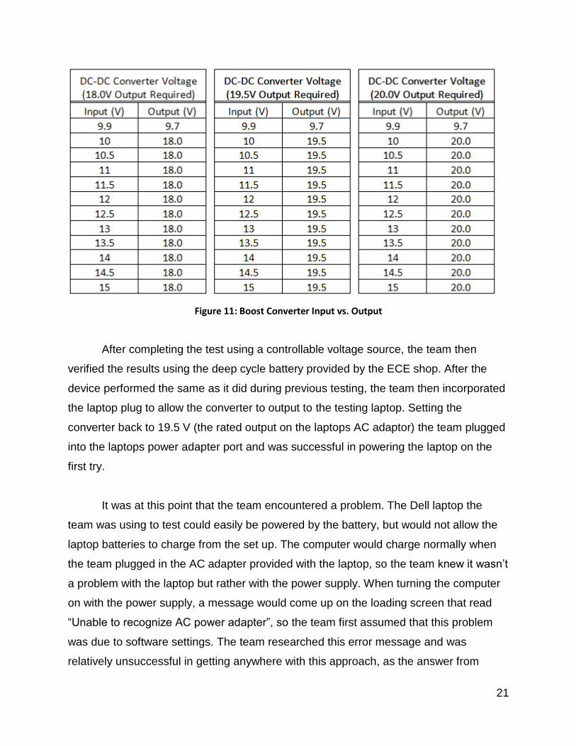
An interesting feature the team discovered when further testing the boost
converters is that after setting the output voltage, the input voltage could sway between
a large range and still output the same voltage. The team tested the device by setting
the potentiometer to output 20.00 V with input of 12 V then varied the input voltage and
recorded the results. The input voltage where the boost converter output would start to
deviate from the expected value was around 9.5 V. The boost converter would continue
to produce a steady output voltage until a higher input voltage than the set output
voltage occurred (when the booster no longer could “boost” the voltage”). It made sense
that the booster would not act as a step down converter, but it was reassuring that the
voltage from the battery could sway during discharge and produce a steady output.
Figure 11 below shows the input vs. output voltage relationships of the boost
converters:
21
Figure 11: Boost Converter Input vs. Output
After completing the test using a controllable voltage source, the team then
verified the results using the deep cycle battery provided by the ECE shop. After the
device performed the same as it did during previous testing, the team then incorporated
the laptop plug to allow the converter to output to the testing laptop. Setting the
converter back to 19.5 V (the rated output on the laptops AC adaptor) the team plugged
into the laptops power adapter port and was successful in powering the laptop on the
first try.
It was at this point that the team encountered a problem. The Dell laptop the
team was using to test could easily be powered by the battery, but would not allow the
laptop batteries to charge from the set up. The computer would charge normally when
the team plugged in the AC adapter provided with the laptop, so the team knew it wasn’t
a problem with the laptop but rather with the power supply. When turning the computer
on with the power supply, a message would come up on the loading screen that read
“Unable to recognize AC power adapter”, so the team first assumed that this problem
was due to software settings. The team researched this error message and was
relatively unsuccessful in getting anywhere with this approach, as the answer from
22
nearly every source was to try another AC power adapter. The team also tried a
multitude of ways to reset hardware drivers and, in a sense, “trick” the laptop into acting
normally, but in the end the team was unsuccessful with this approach.
The team then began reverse engineering the AC adapter provided with the
laptop. What was discovered quickly was that in the plug there was not only a lead and
ground wire, but also a smaller unknown wire which was routed to an integrated circuit
located in the brick of the adapter. Initial research was unsuccessful in finding out what
this unknown wire was or what it accomplished. The signal from this wire was measured
on the oscilloscope, and recorded. The waveform was not a pure sinusoid so the
attempts to mimic it with the function generator proved unsuccessful as well.
Finally the team was successful in touching base with a company selling laptop
charging components and received the crucial information about the blue wire from a
repairman. The blue wire turned out to provide a logic signal from the integrated circuit
located in the brick to the computer, which was then interpreted by the computer to
allow the battery to be charged. He did not know of any way to overcome this, but was
able to tell the team that these were common in all smart chargers, and listed the
brands that have smart chargers. According to this source, Dells and Alienware
machines use these in all of their laptops, as well as certain HP machines. Acer,
Gateway and Toshiba do not use smart chargers, but as the sponsor had expressed
interest in using Dell products so the team continued to investigate try and correct this
issue.
The team finished the project without successfully finding a way to overcome this
problem. It appears to truly mimic this signal and allow the computer to charge will
involve a much larger amount of reverse engineering using a logic analyzer.
Theoretically, if the digital signals could be recorded an IC could be developed to be
integrated into the expandable power supply and correct this issue. However, even if
this was theoretically all solved and implemented, there is no way for us to possibly
know if this signal works on any other models of Dell laptops except for the one the
team had tested. Since the sponsor has not officially chosen a laptop to be powered,

23
the team would not be able to guarantee that this problem would be fixed upon delivery
of the system. Additionally, if the sponsor chooses any other brand of machine other
than Dell, the signals would definitely vary from the testing and prove to be ultimately
meaningless.
An important test conducted prior to building the solar panel array was testing the
duration of the power supply. Using only the deep cycle battery as a power source, the
computer was left on doing various activities allowing the battery to discharge. Referring
to the data sheets provided with the battery, the team determined the voltage at which
point was healthy for the battery to be discharged. With this value, which was around
10.8 V, the team then recorded how long it took for the laptop to discharge the battery to
this voltage from a full charge of 12.8 V.
With the laptop consuming maximum amount of energy doing various high-load
activities, the battery would consistently last over seven hours, which was two hours
more than the minimum that was hoped to be achieved through initial requirements. It is
worth noting that though the team was only testing with one laptop at maximum load,
the team also only had access to a much smaller capacity than what would optimally be
implemented in India, as the battery used in testing is only rated for 30 Ampere-hours
(Ah) compared to some other batteries which have ratings of 80 Ah or more. While the
power supplied still depends on input from the solar panel array, the testing regarding
capacity of the battery bank proved to be more than sufficient to meet the Critical
Customer Requirements. A picture of the computer being powered by the deep-cycle
battery is shown below in Figure 12.

24
Figure 12: Battery Powering a Laptop
The remaining testing of the system now turned to the charging of the battery
bank. The charging controller was the first ordered component to arrive, so it was the
first part of the system to be tested. The team was able to mimic the solar panels using
the bench power supply. In this manner the team was successful in verifying that the
charging controller worked exactly as expected. When applying a reverse voltage
(simulating the batteries being connected backwards) the controller did not allow
reverse current flow, which protects the solar panel array. When voltage was applied
correctly, the controller successfully varied its output to most efficiently charge the
battery, a practice known as maximum power point tracking. This ensured that the

25
controller would efficiently harvest the sun’s energy when the solar panels were added
to the system.
There were a number of tests throughout the construction of the solar panel
array. Prior to each cell being soldered into a panel, the voltage was tested to make
sure the cell was not faulty. Similar voltage tests were repeated throughout the process
to ensure that upon completion the devices would perform as expected. When
completed the panels were tested both individually and as an array for their voltages
and short circuit currents. As shown in Figure 13, the completed solar panels were able
to produce 4.79 V each when subjected to a solar lamp, which corresponds to a 14.37 V
array when all of the panels are connected.
Figure 13: Testing of the Solar Panel
The battery monitor was also testing during this period. Since most deep-cycle
battery manufacturers do not recommend discharging the battery below 11 V, which
was determined to be the zero percent level for the battery monitor. Deep-cycle

26
batteries are around 12.5 V when fully charged, so that was set as the 100 percent
mark for the monitor. To test the code of the battery monitor, a power supply was
connected to the voltage divider circuit and varied from 12.5 V to 11 V in order to ensure
that the battery monitor showed the correct information on the display. Since the
difference between 12.5 V and 11 V is 1.5 V, the battery monitor needed to display 10
percent less for each 0.15 V drop from the power supply. The battery monitor passed
this test and was then transferred from a solderless breadboard to a project board.

27
Chapter 5 The goal of the system was to build an expandable computer power storage
system powered by solar panels so that a laptop computer lab would continue to
function without power from the power grid. The team came up with a design that uses
solar panels to charge deep-cycle batteries, and then use a DC-to-DC converter to
output the correct voltage and current to power the laptops. The team also has built an
LCD monitor to display the remaining battery life by measuring the voltage of the
batteries using a microcontroller’s analog to digital converter function.
The final cost of the project is shown in Figure 14. Throughout the project the
team was able to cut many costs through variety of ways. The most significant cost the
team cut was the purchasing of deep cycle batteries. Since it would be extremely
expensive to ship batteries to India the team was able to borrow these from the ECE
shop for the duration of our project. This allowed a fair amount of testing to be done and
provided proof of concept, but ideally batteries with larger capacity would have been
used to accomplish the charge duration goals. The design has been created under the
assumption that larger capacity batteries will be used at the final destination.
The pricing for DC-DC converters and the charging controller were fairly
accurate, being just slightly cheaper than anticipated. Based on the sponsor’s
experience in India the team decided to construct their own solar panels to both avoid
shipping costs and size the panels to fit in a carry-on aboard an international flight.

28
Component Quantity Price
Solar Panels 2 $225.97
Charging Controller 1 $87.69
Microcontroller + LCD Screen
1 $0.00
DC to DC Boost Converter 4 $36.68
Misc. Integration Components
$76.49
Deep Cycle Batteries 2 $0
Total Price =
$426.83
Figure 14: Final Cost
In order to reduce cost as well as meet the requirements of the sponsor, the
team built several smaller solar panels that could be connected together rather than
purchase commercial ones. After some research, the team was able to design and
deliver four solar panels that are small enough to be carried on a plane to India. The
power from these solar panels is able to sustain the system independently, and the
output is within the safety range of the charging controller as well.
The team had discovered that it was possible to power the computer without
using the commercial power adapter in order to reduce the power loss by the
transformer. Instead of using the factory power adapter, the team has bought several
DC-to-DC converters that will boost the voltage of the battery to power the laptop
computers. The design is significant for the system because reducing the power loss
means the computer lab will keep functioning even longer without the power grid.
Finally, in order to increase the user-friendliness of the system, the team
implemented a microcontroller battery monitor system to provide information about the
remaining charge of the battery. Since over-discharging the battery will reduce its

29
lifetime, it is crucial to keep a track of the remaining battery life. The microcontroller will
keep track of the voltage, and convert the voltage information to a percentage display
on a LCD screen in a one-hundred percent scale.
During the testing phase of the project, multiple segments of the design were
proven to work. The LCD battery monitor was able to display the correct remaining
charge percent when connected to a lab power supply and when connected to the
battery. The constructed solar panels all output 4.79 V each and the solar panel array
output 14.37 V when subjected to a solar lamp during testing. The design was also able
to power a single laptop for 7 hours before needing to recharge the battery.
However, the entire system is still not yet perfect. There are still some issues to
be worked on in the future for another team to improve the design. The first issue of the
system is that the power supply is only able to keep the laptop running without charging
the battery at the same time. The team has figured out that it is because there is a logic
chip built inside the laptop’s AC adapter that controls the charging process. The team
was not able to find a way to mimic the logic chip and charge the battery.
Another issue is the expandability of the system, due to the difference of the
internal resistance of the batteries. Since deep-cycle batteries are very expensive, and
the team does not have enough money in the budget to purchase two identical
batteries, it is very difficult to test the expandability of the system. This is because
putting in batteries with different internal resistances could possibly overcharge or over-
discharge one of the batteries and damage the system.
The team has successfully built and delivered a system that fulfills the basic
requirements set forth by the sponsor. At present, the system is able to store electrical
power from the solar panel and use it to power several laptop computers. However,
there is still room for improvement. And it is certain that with more time and budget the
team would be able to make any necessary improvement in order to develop a better
system.

30
Appendices
Appendix 1 – Technical Roles
Alan Everdeen
Alan’s technical contribution to the project was the design and
implementation of the microcontroller-based battery monitor. The
beginning stages of designing the battery monitor included determining
the best microcontroller to use. The microcontroller needed to balance
price, power consumption, and performance. Alan also had to research which LCD was
needed in order to ensure that the information that needed to be read was displayed
correctly on the screen and that the LCD could interface effectively with the
microcontroller. Also, Alan had to research the best way to monitor the status of the
battery to ensure that the remaining charge of the battery bank is accurately monitored.
After the most effective way to monitor the battery was determined, Alan had to create a
simple circuit to ensure that the microcontroller was not damaged by high voltage. The
microcontroller needed to interface with the LCD and the battery bank, so Alan wrote
code for the microcontroller that first takes input from the battery bank through the
analog to digital converter and processes it and then outputs the status of the battery
bank to the LCD.
Alan was also involved with the testing of the completed system. His contribution to the
testing was monitoring the battery monitor by ensuring that the monitor was displaying
the correct information relative to the voltage reading from the battery bank. This
involved running the battery down to empty and measuring the voltage of the battery
periodically and comparing the voltage reading to the expected output on the LCD.
After everything was tested and proven to work correctly, Alan then had to take the
circuit and plan out how to fit it on to a PCB. He then put all of the parts on the PCB,

31
soldered the circuit together, and tested the circuit again to ensure that everything was
working correctly.
Leon Liang
Leon was in charge of the charging circuit design and solar panel
assembly. Since parts of the project required the team to build smaller
solar panels for transportation purposes, Leon needed to research and
teach others how to correctly build solar panels from solar cells. Before
the team started to assemble solar panels, Leon had prepared a list of
all the tools and parts they were going to need in the assembly process. Also, Leon had
made a test solar cell to test the assembly techniques and the final outcome of his
research. After a few tests and the gathering of data, Leon was able to design the circuit
layout of the solar panels to ensure that they would provide the correct output voltage
and current when they were used to charge the deep cycle batteries.
Moreover, Leon was fully involved in the solar panel assembly process. Since
solar panel assembly is extremely time consuming, Leon could not finish such a task
without help from his teammates. Thus, Leon needed to teach them how the solar cells
worked and how to correctly assemble them using his experience from the testing
process. During the assembly process, Leon distributed the work amongst his
teammates, and Leon was in charge of soldering each individual solar cell. After each
soldering procedure, Leon had to test and monitor the quality of the final product to
ensure everything was working as expected because once the solar cells are sealed
inside the frame, it is nearly impossible to make any changes to them. The entire
building process took the team two days to finish. After finishing the assembly of the
four panels, Leon tested each of the panels with a multimeter in order to make sure that
the output voltage and current was correct for the system.

32
Tommy MacBeth
Tommy’s main technical contribution to the expandable computer
power supply design involved power delivery to the laptop computers,
where he was in charge of choosing, implementing and testing all
components after the battery bank. Early on, this required a fair amount
of research to determine which set-up would yield both the highest
efficiency and be the most user friendly.
Initially inverters were to be used to plug the computer AC adapters into, as it
would allow for any device to be plugged in. However, after the team decided to power
the system strictly with solar panels, it became apparent that the system would be most
efficient if kept completely DC, since the both the input and output were now DC
components. Tommy then created and analyzed multiple designs using various DC-DC
conversion methods. These designs were compared and discussed with the team in
order to arrive at the final configuration which utilized step-up converters. Tommy
chose a style of boost converter which allowed a variable output voltage to ensure
maximum compatibility for any future computer additions.
Once a suitable laptop was chosen for testing Tommy also researched
various specifications to make sure that no harm would come to the computer during
testing and also estimate the duration of the charging system before formal testing of
the completed design could be accomplished. After researching the power requirements
of the laptop, Tommy calibrated the system to output the correct voltage and began
testing to ensure the system performed as expected.
In addition to ensuring accurate power delivery to devices, he also made sure
that system protection was in place to safeguard users from potential shocks and
equipment from short circuit currents. This was completed by both strategically adding
fuses to the system and creating an enclosure for the 12 volt bus bar.

33
Tim Wang
Throughout the semester, Tim assisted in the solar panel testing
and researching aspects for this project. Tim was the primary contact
with the team sponsor, Stephen Blosser, from the Michigan State
University Resource Center for Persons with Disabilities (RCPD). Tim
met with the sponsor and discussed with him the calculations used to
determine the required dimension of the solar panels. In order to determine the
dimensions of solar panels and the materials the panels would be using, Tim took some
key elements into consideration, which included the strength of the panels’ center, ideal
panel material, the size of solar cells, the temperature sensitivity, and the limitation of
carry-on baggage. After meeting with Mr. Blosser, the team eventually determined that
the dimension of the solar panels should be 21” x 21”. Tim also helped build the solar
panels with Leon and Tommy. When building the solar panels, the team needed to be
very careful, as solar cells are very fragile. Tim was responsible for a large amount of
soldering the solar cells together, putting on connectors, and the testing of each of the
panels to ensure that they were functioning correctly.
Once a design was implemented, Tim did some preliminary testing on the DC-
DC converter and Solar panels. Due to the fact that sponsor was having trouble getting
a computer the help the team test, Tim provided an old, but functional, computer for
testing with the DC-DC converter. After testing, Tim determined that the DC-DC
converter can power the computer. He also tested how the input voltage may affect the
output voltage of DC-DC Converter.
34
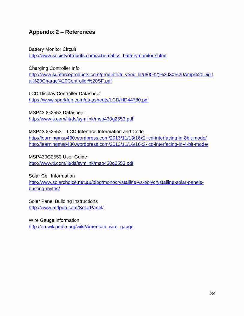
Appendix 2 – References
Battery Monitor Circuit
http://www.societyofrobots.com/schematics_batterymonitor.shtml
Charging Controller Info
http://www.sunforceproducts.com/prodinfo/fr_vend_lit/(60032)%2030%20Amp%20Digit
al%20Charge%20Controller%20SF.pdf
LCD Display Controller Datasheet
https://www.sparkfun.com/datasheets/LCD/HD44780.pdf
MSP430G2553 Datasheet
http://www.ti.com/lit/ds/symlink/msp430g2553.pdf
MSP430G2553 – LCD Interface Information and Code
http://learningmsp430.wordpress.com/2013/11/13/16x2-lcd-interfacing-in-8bit-mode/
http://learningmsp430.wordpress.com/2013/11/16/16x2-lcd-interfacing-in-4-bit-mode/
MSP430G2553 User Guide
http://www.ti.com/lit/ds/symlink/msp430g2553.pdf
Solar Cell Information
http://www.solarchoice.net.au/blog/monocrystalline-vs-polycrystalline-solar-panels-
busting-myths/
Solar Panel Building Instructions
http://www.mdpub.com/SolarPanel/
Wire Gauge information
http://en.wikipedia.org/wiki/American_wire_gauge

35
Appendix 3 – Technical Attachments
Figure 15: Gantt Chart Part 1

36
Figure 16: Gantt Chart Part 2