expanding the station backbone/ increasing crew … the station backbone/ increasing crew...
TRANSCRIPT
WWW.SHUTTLEPRESSKIT.COM
Updated September 5, 2002
Expanding the Station Backbone/Increasing Crew Capabilities
Expanding the Station Backbone/Increasing Crew Capabilities
STS- 112/9A Shuttle Press KitSTS- 112/9A Shuttle Press Kit
STS-112 Shuttle Press Kit National Aeronautics and Space Administration
Table of Contents
Mission Overview ..................................................................................................... 1
Timeline Overview ................................................................................................... 7
Mission Objectives ................................................................................................ 12
Mission Profile ....................................................................................................... 13
Crewmembers ........................................................................................................ 15
Rendezvous and Docking ..................................................................................... 24
Spacewalks
STS-112 Extravehicular Activities ............................................................................ 27
Payloads
Payload Overview..................................................................................................... 35
S1 Truss .................................................................................................................. 39
International Space Station S1 and P1 Truss Summary .......................................... 42
Crew and Equipment Translation Aid Cart A ........................................................... 45
Spatial Heterodyne Imager for Mesospheric Radicals (SHIMMER) ......................... 49
Experiments
Science Overview .................................................................................................... 50
DSOs and DTOs ...................................................................................................... 52
Ram Burn Observations ........................................................................................... 57
STS-112 Shuttle Press Kit National Aeronautics and Space Administration
Shuttle Reference Data
Shuttle Abort History ................................................................................................ 58
Shuttle Abort Modes ................................................................................................ 60
Shuttle Rendezvous Maneuvers .............................................................................. 64
Space Shuttle Main Engines .................................................................................... 65
Shuttle Solid Rocket Boosters .................................................................................. 67
Shuttle Super-lightweight Tank ................................................................................ 75
Acronyms and Abbreviations ............................................................................... 76
Media Assistance ................................................................................................... 86
Media Contacts ...................................................................................................... 88
STS-112 Shuttle Press Kit National Aeronautics and Space Administration
Mission Overview
Expanding Station Backbone, Increasing Crew Capabilities
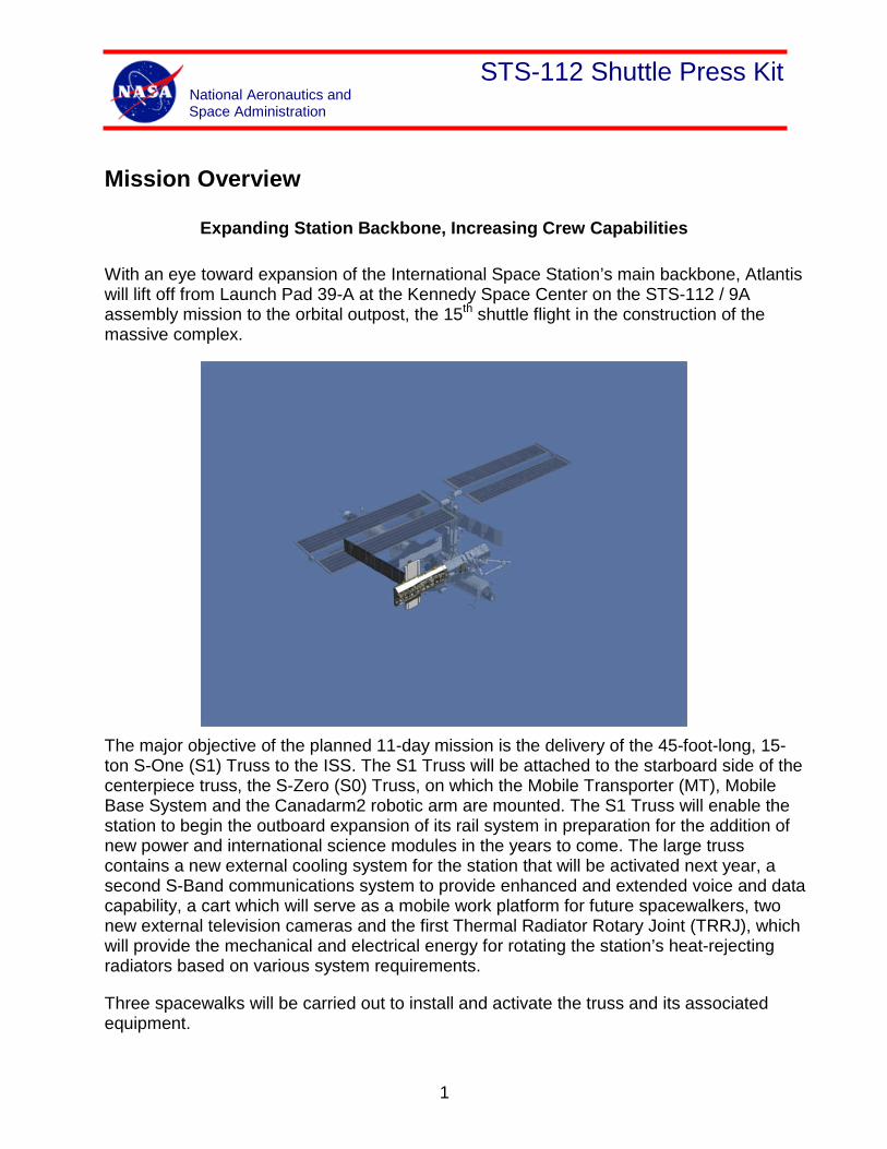
With an eye toward expansion of the International Space Station’s main backbone, Atlantis will lift off from Launch Pad 39-A at the Kennedy Space Center on the STS-112 / 9A assembly mission to the orbital outpost, the 15th shuttle flight in the construction of the massive complex.
The major objective of the planned 11-day mission is the delivery of the 45-foot-long, 15-ton S-One (S1) Truss to the ISS. The S1 Truss will be attached to the starboard side of the centerpiece truss, the S-Zero (S0) Truss, on which the Mobile Transporter (MT), Mobile Base System and the Canadarm2 robotic arm are mounted. The S1 Truss will enable the station to begin the outboard expansion of its rail system in preparation for the addition of new power and international science modules in the years to come. The large truss contains a new external cooling system for the station that will be activated next year, a second S-Band communications system to provide enhanced and extended voice and data capability, a cart which will serve as a mobile work platform for future spacewalkers, two new external television cameras and the first Thermal Radiator Rotary Joint (TRRJ), which will provide the mechanical and electrical energy for rotating the station’s heat-rejecting radiators based on various system requirements.
Three spacewalks will be carried out to install and activate the truss and its associated equipment.
1
STS-112 Shuttle Press Kit National Aeronautics and Space Administration
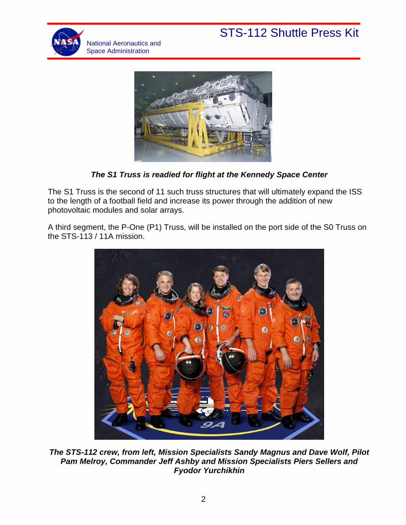
The S1 Truss is readied for flight at the Kennedy Space Center
The S1 Truss is the second of 11 such truss structures that will ultimately expand the ISS to the length of a football field and increase its power through the addition of new photovoltaic modules and solar arrays.
A third segment, the P-One (P1) Truss, will be installed on the port side of the S0 Truss on the STS-113 / 11A mission.
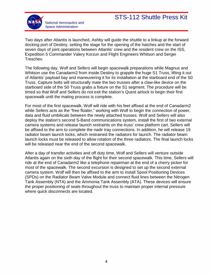
The STS-112 crew, from left, Mission Specialists Sandy Magnus and Dave Wolf, Pilot Pam Melroy, Commander Jeff Ashby and Mission Specialists Piers Sellers and
Fyodor Yurchikhin
2

STS-112 Shuttle Press Kit National Aeronautics and Space Administration
Atlantis’ mission to the ISS is commanded by Jeff Ashby (Capt., USN), who will be making his third flight into space after two previous missions as a pilot, including the STS-100 mission to the station in 2001 to deliver the Canadarm2. Ashby will be joined on the flight deck by Pilot Pam Melroy (Col., USAF), who is making her second flight to the ISS after piloting the STS-92 mission that brought the Z-One (Z1) Truss to the Unity module.
First-time shuttle flier Sandy Magnus (Ph.D.) will serve as Atlantis’ flight engineer and will be one of the operators of the Canadarm2 robotic arm once Atlantis reaches the ISS. The large arm will be employed for the installation of the S1 Truss and the transport of the spacewalkers as they conduct their connections of power and data cables and other external hardware to the truss itself. Magnus will be assisted in the robotics work by Expedition 5 Flight Engineer Peggy Whitson from the Destiny Laboratory of the station.
Veteran Astronaut David Wolf (M.D.) is one of two spacewalkers on STS-112, making his third flight into space, including a 119-day mission as a flight engineer on the former Russian space station Mir. Wolf conducted a spacewalk during his tenure on the Mir in 1998, collecting experiments from the exterior of the station along with his Commander, Anatoly Solovyev.
Piers Sellers (Ph.D.) is making his spaceflight debut on STS-112 as the other spacewalker who will join Wolf outside Atlantis for the truss and hardware installation tasks. The other first-time crewmember is Russian Engineer Fyodor Yurchikhin from RSC-Energia who will join Melroy as one of two spacewalk choreographers during the mission and who will work with Magnus in the transfer of experiments and payloads from Atlantis to the ISS during docked operations.
The International Space Station’s forward PMA
3
STS-112 Shuttle Press Kit National Aeronautics and Space Administration
Two days after Atlantis is launched, Ashby will guide the shuttle to a linkup at the forward docking port of Destiny, setting the stage for the opening of the hatches and the start of seven days of joint operations between Atlantis’ crew and the resident crew on the ISS, Expedition 5 Commander Valery Korzun and Flight Engineers Whitson and Sergei Treschev.
The following day, Wolf and Sellers will begin spacewalk preparations while Magnus and Whitson use the Canadarm2 from inside Destiny to grapple the huge S1 Truss, lifting it out of Atlantis’ payload bay and maneuvering it for its installation at the starboard end of the S0 Truss. Capture bolts will structurally mate the two trusses after a claw-like device on the starboard side of the S0 Truss grabs a fixture on the S1 segment. The procedure will be timed so that Wolf and Sellers do not exit the station’s Quest airlock to begin their first spacewalk until the mating process is complete.
For most of the first spacewalk, Wolf will ride with his feet affixed at the end of Canadarm2 while Sellers acts as the “free floater,” working with Wolf to begin the connection of power, data and fluid umbilicals between the newly attached trusses. Wolf and Sellers will also deploy the station’s second S-Band communications system, install the first of two external camera systems and release launch restraints on the truss’ crew platform cart. Sellers will be affixed to the arm to complete the nadir tray connections. In addition, he will release 19 radiator beam launch locks, which restrained the radiators for launch. The radiator beam launch locks must be released to allow rotation of the three radiators. The final launch locks will be released near the end of the second spacewalk.
After a day of transfer activities and off duty time, Wolf and Sellers will venture outside Atlantis again on the sixth day of the flight for their second spacewalk. This time, Sellers will ride at the end of Canadarm2 like a telephone repairman at the end of a cherry picker for most of the spacewalk. The second excursion is designed to set up the second external camera system. Wolf will then be affixed to the arm to install Spool Positioning Devices (SPDs) on the Radiator Beam Valve Module and connect fluid lines between the Nitrogen Tank Assembly (NTA) and the Ammonia Tank Assembly (ATA). These devices will ensure the proper positioning of seals throughout the truss to maintain proper internal pressure where quick disconnects are located.
4
STS-112 Shuttle Press Kit National Aeronautics and Space Administration
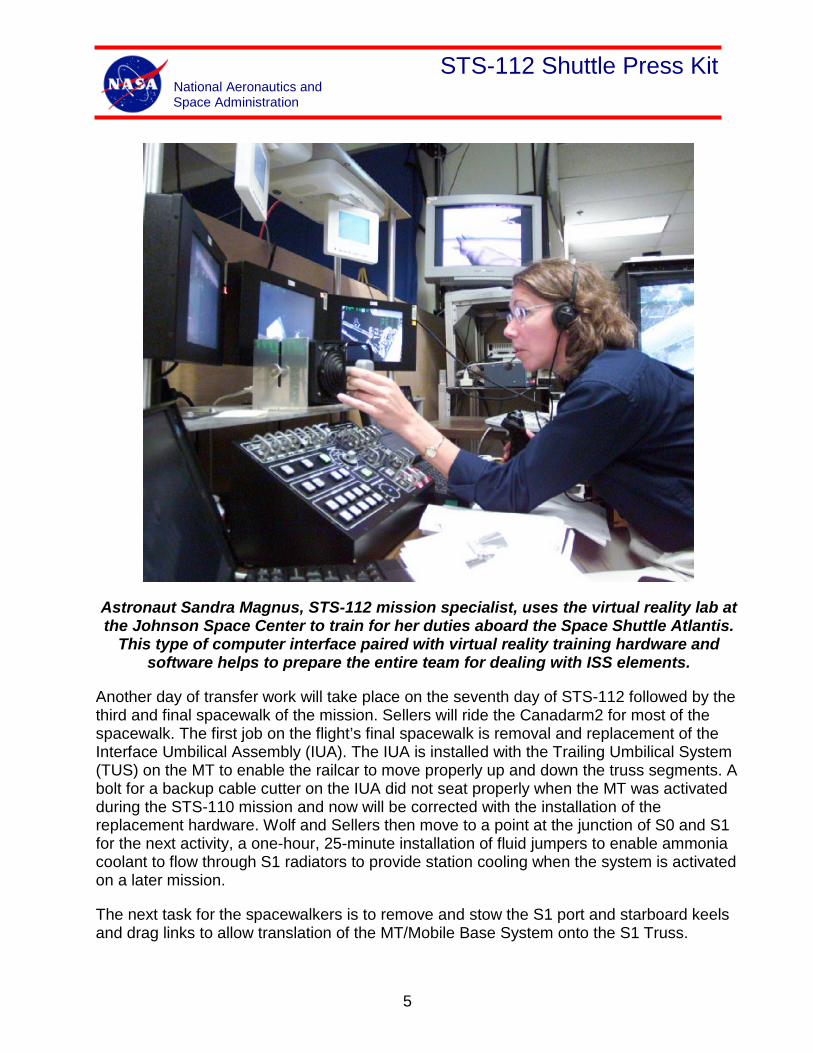
Astronaut Sandra Magnus, STS-112 mission specialist, uses the virtual reality lab at the Johnson Space Center to train for her duties aboard the Space Shuttle Atlantis.
This type of computer interface paired with virtual reality training hardware and software helps to prepare the entire team for dealing with ISS elements.
Another day of transfer work will take place on the seventh day of STS-112 followed by the third and final spacewalk of the mission. Sellers will ride the Canadarm2 for most of the spacewalk. The first job on the flight’s final spacewalk is removal and replacement of the Interface Umbilical Assembly (IUA). The IUA is installed with the Trailing Umbilical System (TUS) on the MT to enable the railcar to move properly up and down the truss segments. A bolt for a backup cable cutter on the IUA did not seat properly when the MT was activated during the STS-110 mission and now will be corrected with the installation of the replacement hardware. Wolf and Sellers then move to a point at the junction of S0 and S1 for the next activity, a one-hour, 25-minute installation of fluid jumpers to enable ammonia coolant to flow through S1 radiators to provide station cooling when the system is activated on a later mission.
The next task for the spacewalkers is to remove and stow the S1 port and starboard keels and drag links to allow translation of the MT/Mobile Base System onto the S1 Truss.
5
STS-112 Shuttle Press Kit National Aeronautics and Space Administration
Another task for the final scheduled spacewalk is Installation of SPDs onto the TRRJ stringer Quick Disconnects.
All three spacewalks are expected to last about 6 to 6 ½ hours.
The next day, Flight Day 9, the shuttle and station crews will complete some additional transfer work and get-ahead tasks for future assembly flights before saying goodbye to one another on Flight Day 10 as the hatches are closed between the vehicles. Melroy will be at the controls as Atlantis undocks from the ISS. She will back the orbiter away from the station to a point about 400 feet in front of the complex before initiating a flyaround of the outpost to enable her crewmates to conduct photo and television documentation of the newly expanded facility.
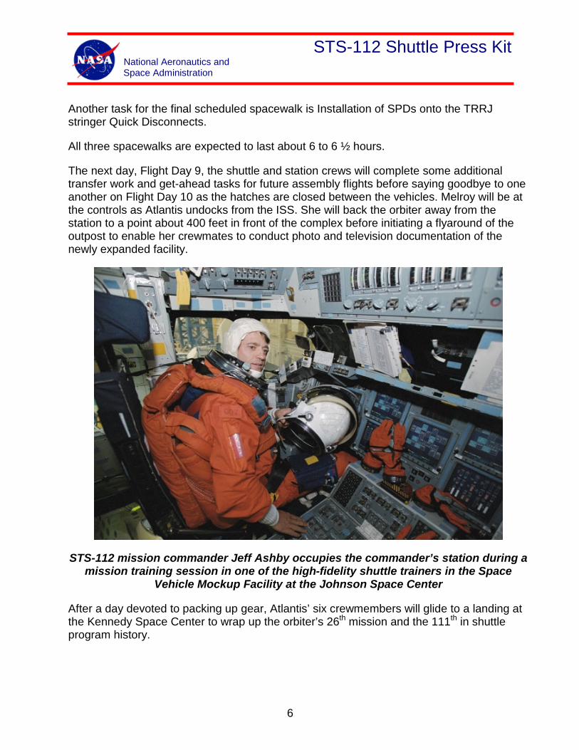
STS-112 mission commander Jeff Ashby occupies the commander’s station during a mission training session in one of the high-fidelity shuttle trainers in the Space
Vehicle Mockup Facility at the Johnson Space Center
After a day devoted to packing up gear, Atlantis’ six crewmembers will glide to a landing at the Kennedy Space Center to wrap up the orbiter’s 26th mission and the 111th in shuttle program history.
6
STS-112 Shuttle Press Kit National Aeronautics and Space Administration
Timeline Overview
Flight Day 1:
• Following launch, crew performs minimal activities before going to sleep.
• International Space Station crew has off duty and sleep shifts in preparation of shuttle docking.
Flight Day 2:
• Shuttle crew performs middeck ISS payload status checks, checkouts of the shuttle robotic arm, spacewalkers’ spacesuits, rendezvous tools and prepares for transfer.
• The shuttle RMS is left powered on in preparation of the S1 installation activities on Flight Day 4.
• The secondary payload SHIMMER is checked out and DTO 700-14/MAGR is set up.
• The shuttle crew goes to bed two hours earlier in support of tomorrow’s rendezvous activities.
• ISS crew has off duty and completes any sleep shifting required.
Flight Day 3:
• A shuttle wastewater dump is scheduled in the crew morning before the start of rendezvous activities.
• Docking occurs in the crew’s afternoon. Hatches are opened about two hours after docking.
• The first two CWCs are filled after the hatches are open. The CWCs used for water transfer are from ISS, so no CWC fills can be done before hatch opening.
• The spacesuits and airlock are prepared for tomorrow’s EVA activities.
• A setup of the shuttle oxygen configuration for the EVA pre-breathe protocol is scheduled late in the crew day.
7
STS-112 Shuttle Press Kit National Aeronautics and Space Administration
• An SSRMS tag-up is scheduled between MS2 and FE-1 to allow SSRMS operators preparation time for tomorrow morning’s S1 Truss installation. The shuttle CDR will participate as time is available to him.
• An EVA procedure review is scheduled for all crewmembers before pre-sleep. The procedure review gives the crew time to review tomorrow’s EVA plan.
Flight Day 4:
• The shuttle crew has two hours of post-sleep scheduled before the start of S1 installation activities and EVA preparation.
• During EVA preparation, the S1 Truss is installed by the SSRMS with the shuttle RMS used for viewing purposes.
• ISS power (channel ¼) must be powered down before the EVA crew connects the zenith side power umbilicals. MCC-H powers channel ¼ on and channel 2/3 is powered down before the EVA crew connects the nadir side umbilicals. A checkout will be performed by MCC-H after each string is powered on. Channel ¼ will be checked out before channel 2/3 is powered off.
• The EVA crew will deploy the S-band antenna while MCC is checking out channel ¼ and powering down string 2.
• Other EVA tasks performed this day are release of the radiator beam launch locks, SASA deploy, ETVCG outboard nadir installation and release of the CETA cart launch locks.
• The shuttle RMS is powered off after EVA 1 and will remain off until Flight Day 6.
Flight Day 5:
• Shuttle crew off duty is scheduled.
• Shuttle nitrogen transfer to ISS is started in late morning and will be terminated on Flight Day 9.
• MSFC payloads, PCG-STES 007 and 008 and the STELSYS CBOSS, are transferred this day.
• The EVA crewmembers perform activities in preparation for EVA 2 such as Extravehicular Mobility Unit (EMU) water recharge, tool configuration and airlock preparation.
• An EVA procedure review is scheduled for both crews before pre-sleep this evening.
8
STS-112 Shuttle Press Kit National Aeronautics and Space Administration
Flight Day 6:
• A one-hour shuttle reboost is scheduled during EVA prep.
• EVA 2 activities include Z1 to P6 and PVR SPDS, Z1 to Lab loop A umbilicals, ATA umbilical, ETVCG starboard installation, SPD installation on RBVM and the last of the launch lock release bolts.
• Two CWCs and a PWR (for spacesuit water recharge) are filled and transferred to the ISS.
• The ISS crew will perform the MSFC payload ZCG activities this day. ZCG has a microgravity constraint for 24 hours once activated.
• Overnight the MCC will check out the starboard ETVCG that was installed during EVA 2.
Flight Day 7:
• The shuttle crew reconfigures and initiates an oxygen transfer to the high-pressure gas tanks on Quest in the morning. Oxygen will be transferred for about eight hours.
• The ISS crew will perform the ISS TVIS Remove and Replace most of the day.
• The EVA crew performs EVA 3 preparation activities in the morning and transfer in the afternoon.
• The MSFC payload PGBA is transferred to the ISS by the shuttle crew.
• The crew photo and conference are scheduled in the afternoon.
• Once the oxygen transfer is completed, a reconfiguration to the shuttle oxygen pre-breather protocol is done late in the afternoon.
• A few hours after the TRRJ pointing checkout is completed, MCC will deploy the S1 radiator. The MS4 will take pictures of the radiator during the deployment.
• An EVA procedure review is scheduled for all crewmembers before pre-sleep.
Flight Day 8:
• Oxygen from the shuttle will be used for the pre-breathe activity.
• A one-hour shuttle reboost is scheduled during the EVA prep timeframe.
9
STS-112 Shuttle Press Kit National Aeronautics and Space Administration
• EVA 3 tasks include IUA R&R, S1 to S0 fluid jumper connections, removal of port and starboard keel pins, last of the TRRJ SPDs, TRRJ bolts and S1 to S1 clamps.
• Three CWCs are filled and transferred to the ISS. The total number of CWCs filled and transferred including the three from this day are 14.
Flight Day 9:
• The shuttle crew has four hours of off duty scheduled.
• The last of the transfer items are taken over to the ISS including the shuttle SAFERs.
• The EMUs are reconfigured in support of leaving a good EMU suit for an ISS crewmember. Once the EMUs are reconfigured, one will be left on the ISS and the other brought back on the shuttle.
• The MSFC payload CGBA is transferred to the ISS.
• The last two CWCs and PWR are filled and transferred to the ISS. A total of 16 CWCs are transferred to the ISS.
• A rendezvous tools checkout is scheduled. The checkout is done in preparation for undock the next day.
• A teardown of the shuttle oxygen configuration for the EVA pre-breathe protocol is scheduled late in the crew day.
Flight Day 10:
• The hatches are closed and the undock activities are completed.
• After flyaround of the ISS by the shuttle, the shuttle crew will perform SHIMMER data takes.
• A wastewater and condensate CWC water dump are scheduled.
• A shuttle crew only PAO event is scheduled in the afternoon.
10
STS-112 Shuttle Press Kit National Aeronautics and Space Administration
Flight Day 11:
• Shuttle crew prepares for landing tomorrow by performing cabin stow and end-of-mission checkouts.
• SHIMMER data takes are scheduled in the morning and a PAO event is in the afternoon.
Flight Day 12:
• DTO 700-14/MAGR entry setup is completed before deorbit prep.
• Shuttle lands.
11
STS-112 Shuttle Press Kit National Aeronautics and Space Administration
Mission Objectives
These major tasks, listed in order of International Space Station Program priority, are to be performed during this flight:
• Perform critical water transfer from shuttle to International Space Station
• Transfer, using the Space Station Remote Manipulator System, install and safe the Integrated Truss Segment (ITS) S1 to ITS S0 starboard side
• Deploy and safe the S1 S-Band Antenna Structural Assembly
• Transfer critical items per Flight 9A Transfer Priority List
• Perform mandatory daily maintenance for powered middeck and U.S. lab payloads
• Transfer remaining items per Flight 9A Transfer Priority List
• Install critical Spool Positioning Devices
• Complete S1 remaining Zenith and Nadir tray utility connections
• Perform Thermal Radiator Rotary Joint checkout
• Deploy S1 central radiator
• Disconnect the Squib Firing Units harness reposition to the radiator beam line heaters and activate S1 fluid line secondary heaters
• IUA remove and replace
• Connect S0 to S1 fluid jumpers
• Connect Ammonia Tank Assembly nitrogen and ammonia lines
• Install second group of Spool Positioning Devices
• Configure inboard section of the MT/CETA translation path
• Release CETA cart
• Complete additional ISS consumables transfer
• Configure outboard section of the MT/CETA translation path
12
STS-112 Shuttle Press Kit National Aeronautics and Space Administration
Mission Profile
Crew
Commander: Jeffrey S. Ashby
Pilot: Pamela Ann Melroy
Mission Specialist 1: David A. Wolf
Mission Specialist 2: Sandra H. Magnus
Mission Specialist 3: Piers J. Sellers
Mission Specialist 4: Fyodor Nikolayevich Yurchikhin
Launch
Orbiter: Atlantis (OV-104)
Launch Site: Kennedy Space Center Launch Pad 39A
Launch Date: No Earlier Than Oct. 2, 2002
Launch Window: 5 Minutes
Altitude: 122 Nautical Miles (Orbital Insertion); 215 NM (Rendezvous)
Inclination: 51.6 Degrees
Duration: 10 Days 19 Hrs. 12 Min.
Vehicle Data
Shuttle Liftoff Weight: 4,521,436 lbs.
Orbiter/Payload Liftoff Weight: 256,917 lbs.
Orbiter/Payload Landing Weight: 201,476 lbs.
13
STS-112 Shuttle Press Kit National Aeronautics and Space Administration
Software Version: OI-29
Space Shuttle Main Engines:
SSME 1: 2048 SSME 2: 2051 SSME 3: 2047
External Tank: ET-115A (Super Light Weight Tank)
SRB Set: BI115PF
Shuttle Aborts
Abort Landing Sites
RTLS: Kennedy Space Center Shuttle Landing Facility
TAL: Primary – Zaragoza; Alternates Ben Guerir, Moron
AOA: Kennedy Space Center Shuttle Landing Facility
Landing
Landing Date: Oct. 13, 2002
Primary Landing Site: Kennedy Space Center
Shuttle Landing Facility
14
STS-112 Shuttle Press Kit National Aeronautics and Space Administration
Crewmembers
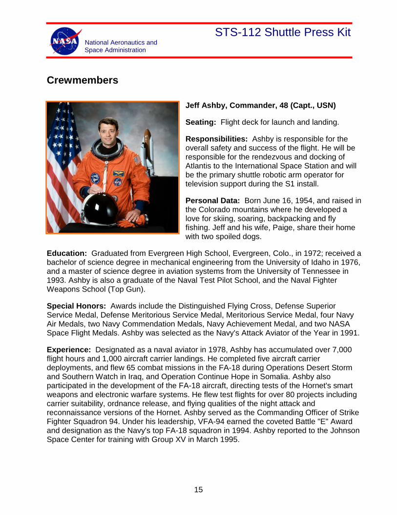
Jeff Ashby, Commander, 48 (Capt., USN)
Seating: Flight deck for launch and landing.
Responsibilities: Ashby is responsible for the overall safety and success of the flight. He will be responsible for the rendezvous and docking of Atlantis to the International Space Station and will be the primary shuttle robotic arm operator for television support during the S1 install.
Personal Data: Born June 16, 1954, and raised in the Colorado mountains where he developed a love for skiing, soaring, backpacking and fly fishing. Jeff and his wife, Paige, share their home with two spoiled dogs.
Education: Graduated from Evergreen High School, Evergreen, Colo., in 1972; received a bachelor of science degree in mechanical engineering from the University of Idaho in 1976, and a master of science degree in aviation systems from the University of Tennessee in 1993. Ashby is also a graduate of the Naval Test Pilot School, and the Naval Fighter Weapons School (Top Gun).
Special Honors: Awards include the Distinguished Flying Cross, Defense Superior Service Medal, Defense Meritorious Service Medal, Meritorious Service Medal, four Navy Air Medals, two Navy Commendation Medals, Navy Achievement Medal, and two NASA Space Flight Medals. Ashby was selected as the Navy's Attack Aviator of the Year in 1991.
Experience: Designated as a naval aviator in 1978, Ashby has accumulated over 7,000 flight hours and 1,000 aircraft carrier landings. He completed five aircraft carrier deployments, and flew 65 combat missions in the FA-18 during Operations Desert Storm and Southern Watch in Iraq, and Operation Continue Hope in Somalia. Ashby also participated in the development of the FA-18 aircraft, directing tests of the Hornet's smart weapons and electronic warfare systems. He flew test flights for over 80 projects including carrier suitability, ordnance release, and flying qualities of the night attack and reconnaissance versions of the Hornet. Ashby served as the Commanding Officer of Strike Fighter Squadron 94. Under his leadership, VFA-94 earned the coveted Battle "E" Award and designation as the Navy's top FA-18 squadron in 1994. Ashby reported to the Johnson Space Center for training with Group XV in March 1995.
15
STS-112 Shuttle Press Kit National Aeronautics and Space Administration
Spaceflights:
STS-93 - Ashby's first spaceflight was in July 1999 as pilot aboard Space Shuttle Columbia which deployed the Chandra X-ray Observatory. Chandra is the third in a series of NASA's Great Observatories following the Hubble Space Telescope and the Compton Gamma Ray Observatory. Chandra was designed to conduct comprehensive studies of the universe, and has enabled scientists to study exotic phenomena such as exploding stars, quasars, and black holes.
STS-100 - Ashby flew as pilot aboard Space Shuttle Endeavour in April 2001, on assembly flight 6A of the International Space Station. This was the most complex robotics flight in the history of the Space Shuttle Program, responsible for installing both the Canadian-built robotic arm, and the Italian-made Logistics Module "Raffaello". Ashby operated the shuttle robotic arm to lift a pallet containing the space station robotic arm from Endeavour's payload bay, and attached it to the International Space Station. After undocking Endeavour from the station, Ashby piloted a unique separation and fly-around profile that enabled IMAX-3D images of the International Space Station.
Ashby has flown a total of 267 orbits around the Earth and logged over 400 hours in space.
16
STS-112 Shuttle Press Kit National Aeronautics and Space Administration
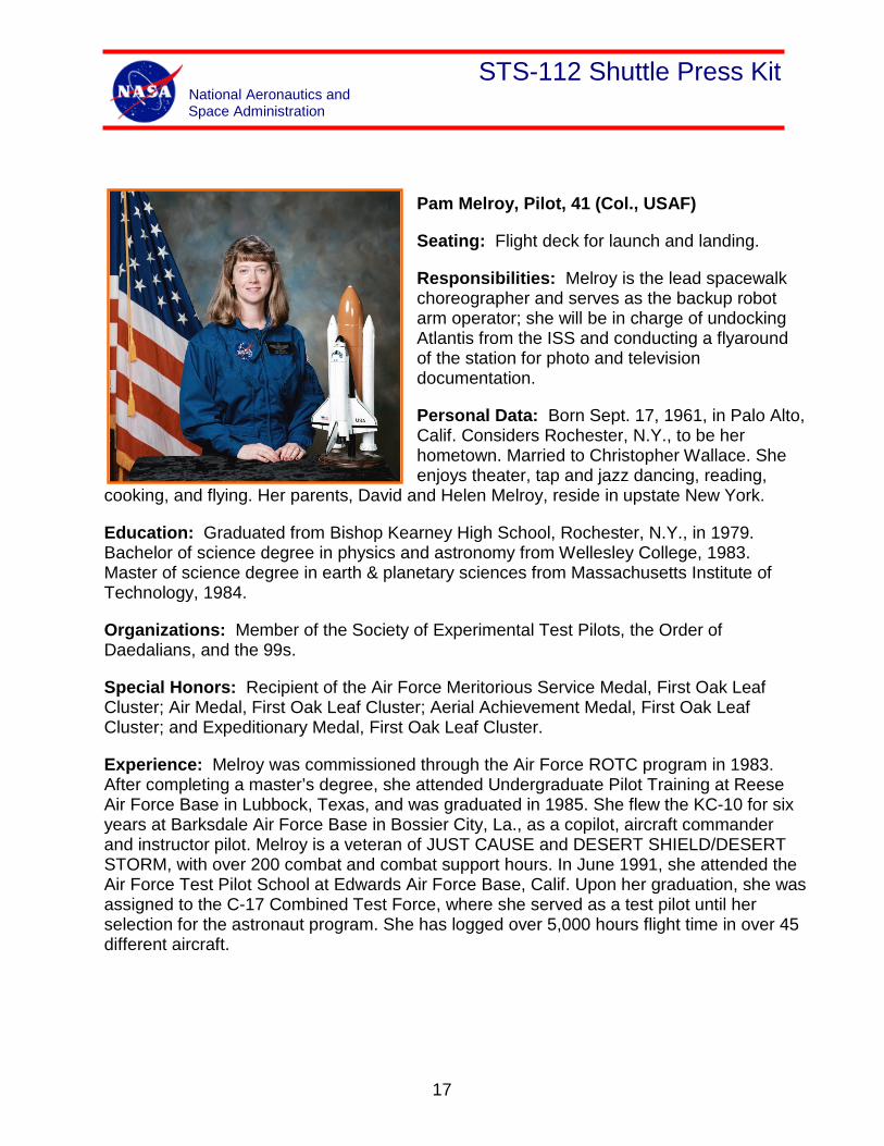
Pam Melroy, Pilot, 41 (Col., USAF)
Seating: Flight deck for launch and landing.
Responsibilities: Melroy is the lead spacewalk choreographer and serves as the backup robot arm operator; she will be in charge of undocking Atlantis from the ISS and conducting a flyaround of the station for photo and television documentation.
Personal Data: Born Sept. 17, 1961, in Palo Alto, Calif. Considers Rochester, N.Y., to be her hometown. Married to Christopher Wallace. She enjoys theater, tap and jazz dancing, reading,
cooking, and flying. Her parents, David and Helen Melroy, reside in upstate New York.
Education: Graduated from Bishop Kearney High School, Rochester, N.Y., in 1979. Bachelor of science degree in physics and astronomy from Wellesley College, 1983. Master of science degree in earth & planetary sciences from Massachusetts Institute of Technology, 1984.
Organizations: Member of the Society of Experimental Test Pilots, the Order of Daedalians, and the 99s.
Special Honors: Recipient of the Air Force Meritorious Service Medal, First Oak Leaf Cluster; Air Medal, First Oak Leaf Cluster; Aerial Achievement Medal, First Oak Leaf Cluster; and Expeditionary Medal, First Oak Leaf Cluster.
Experience: Melroy was commissioned through the Air Force ROTC program in 1983. After completing a master’s degree, she attended Undergraduate Pilot Training at Reese Air Force Base in Lubbock, Texas, and was graduated in 1985. She flew the KC-10 for six years at Barksdale Air Force Base in Bossier City, La., as a copilot, aircraft commander and instructor pilot. Melroy is a veteran of JUST CAUSE and DESERT SHIELD/DESERT STORM, with over 200 combat and combat support hours. In June 1991, she attended the Air Force Test Pilot School at Edwards Air Force Base, Calif. Upon her graduation, she was assigned to the C-17 Combined Test Force, where she served as a test pilot until her selection for the astronaut program. She has logged over 5,000 hours flight time in over 45 different aircraft.
17
STS-112 Shuttle Press Kit National Aeronautics and Space Administration
NASA Experience: Selected as an astronaut candidate by NASA in December 1994, Melroy reported to the Johnson Space Center in March 1995. She completed a year of training and evaluation and is qualified for flight assignment as a shuttle pilot. Initially assigned to astronaut support duties for launch and landing, she has also worked Advanced Projects for the Astronaut Office. She was the pilot on STS-92 in 2000 and has logged over 309 hours in space.
Spaceflight Experience: STS-92 Discovery (Oct. 11-24, 2000) was launched from the Kennedy Space Center, Fla., and returned to land at Edwards Air Force Base, Calif. During the 13-day flight, the seven-member crew attached the Z1 Truss and Pressurized Mating Adapter 3 to the International Space Station using Discovery's robotic arm and performed four spacewalks to configure these elements. This expansion of the ISS opened the door for future assembly missions and prepared the station for its first resident crew. The STS-92 mission was accomplished in 202 orbits, traveling 5.3 million miles in 12 days, 21 hours, 40 minutes and 25 seconds.
18
STS-112 Shuttle Press Kit National Aeronautics and Space Administration
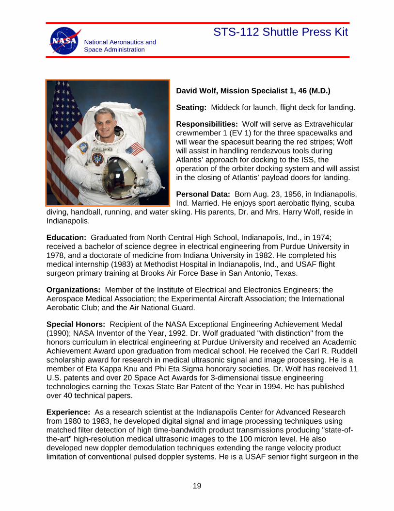
David Wolf, Mission Specialist 1, 46 (M.D.)
Seating: Middeck for launch, flight deck for landing.
Responsibilities: Wolf will serve as Extravehicular crewmember 1 (EV 1) for the three spacewalks and will wear the spacesuit bearing the red stripes; Wolf will assist in handling rendezvous tools during Atlantis’ approach for docking to the ISS, the operation of the orbiter docking system and will assist in the closing of Atlantis’ payload doors for landing.
Personal Data: Born Aug. 23, 1956, in Indianapolis, Ind. Married. He enjoys sport aerobatic flying, scuba
diving, handball, running, and water skiing. His parents, Dr. and Mrs. Harry Wolf, reside in Indianapolis.
Education: Graduated from North Central High School, Indianapolis, Ind., in 1974; received a bachelor of science degree in electrical engineering from Purdue University in 1978, and a doctorate of medicine from Indiana University in 1982. He completed his medical internship (1983) at Methodist Hospital in Indianapolis, Ind., and USAF flight surgeon primary training at Brooks Air Force Base in San Antonio, Texas.
Organizations: Member of the Institute of Electrical and Electronics Engineers; the Aerospace Medical Association; the Experimental Aircraft Association; the International Aerobatic Club; and the Air National Guard.
Special Honors: Recipient of the NASA Exceptional Engineering Achievement Medal (1990); NASA Inventor of the Year, 1992. Dr. Wolf graduated "with distinction" from the honors curriculum in electrical engineering at Purdue University and received an Academic Achievement Award upon graduation from medical school. He received the Carl R. Ruddell scholarship award for research in medical ultrasonic signal and image processing. He is a member of Eta Kappa Knu and Phi Eta Sigma honorary societies. Dr. Wolf has received 11 U.S. patents and over 20 Space Act Awards for 3-dimensional tissue engineering technologies earning the Texas State Bar Patent of the Year in 1994. He has published over 40 technical papers.
Experience: As a research scientist at the Indianapolis Center for Advanced Research from 1980 to 1983, he developed digital signal and image processing techniques using matched filter detection of high time-bandwidth product transmissions producing "state-of-the-art" high-resolution medical ultrasonic images to the 100 micron level. He also developed new doppler demodulation techniques extending the range velocity product limitation of conventional pulsed doppler systems. He is a USAF senior flight surgeon in the
19
STS-112 Shuttle Press Kit National Aeronautics and Space Administration
Air National Guard (1982 to present) and is a member of the Board of Directors of the National Inventors Hall of Fame. He has logged over 2,000 hours of flight time including air combat training as a weapons systems officer (F4 Phantom jet), T-38 Talon, and competition aerobatics (PITTS Special and Christen Eagle).
NASA Experience: In 1983, Dr. Wolf joined the Medical Sciences Division, Johnson Space Center, Houston, Texas. He was responsible for development of the American Flight Echocardiograph for investigating cardiovascular physiology in microgravity. Upon completion he was assigned as chief engineer for design of the space station medical facility. In 1986 he was assigned to direct development of the Space Bioreactor and associated tissue engineering and cancer research applications using controlled gravitational conditions. This resulted in the state-of-the-art NASA rotating tissue culture systems. He has particular expertise in the design of real-time computer process control systems, communications, bioprocessing, physiology, fluid dynamics, and aerospace medicine. Dr. Wolf is an active public speaker.
Selected as a NASA astronaut in January 1990, Dr. Wolf became qualified for spaceflight in July 1991. His technical assignments have included Orbiter vehicle processing and test at Kennedy Space Center (1991-1992) and spacecraft communications (CAPCOM) (1994-1995). He is qualified for Extravehicular Activity (Spacewalk), Remote Manipulator System (Robot Arm), and Rendezvous. He was CAPCOM for the first and third Shuttle-Mir rendezvous. He trained at the Gagarin Cosmonaut Training Center in Star City, Russia, in preparation for a long-duration stay aboard Mir. Most recently, he was assigned to the EVA Development Group focusing on assembly techniques for the International Space Station. Dr. Wolf has logged 142 days in space including a 4-hour EVA in a Russian Orlan spacesuit. He was a mission specialist on STS-58, and served as Board Engineer 2 for 119 days aboard the Russian Space Station Mir.
Spaceflight Experience: STS-58 Columbia (Oct. 16 to Nov. 1, 1993) was a 14-day dedicated Spacelab life sciences research mission. During this record length shuttle mission, the crew conducted neurovestibular, cardiovascular, cardiopulmonary, metabolic, and musculoskeletal research using microgravity to reveal fundamental physiology normally masked by Earth gravity. Mission duration was 336 hours, 13 minutes, 01 second. On Sept. 25, 1997, Dr. Wolf launched aboard Space Shuttle Atlantis as part of the STS-86 crew. Following docking, Sept. 28, 1997, marked the official start of his 119 days aboard Mir. He returned with the crew of STS-89 aboard Shuttle Endeavour on Jan. 31, 1998. Mission duration was 119 days.
20
STS-112 Shuttle Press Kit National Aeronautics and Space Administration
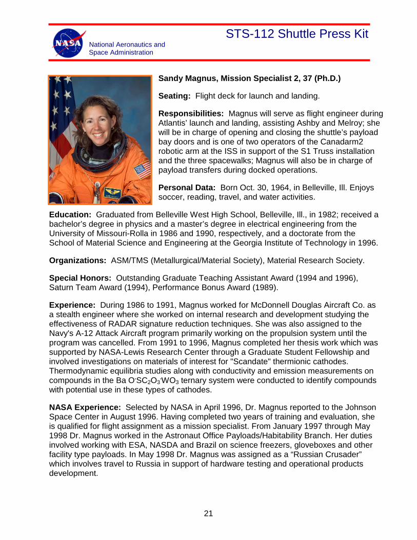
Sandy Magnus, Mission Specialist 2, 37 (Ph.D.)
Seating: Flight deck for launch and landing.
Responsibilities: Magnus will serve as flight engineer during Atlantis’ launch and landing, assisting Ashby and Melroy; she will be in charge of opening and closing the shuttle’s payload bay doors and is one of two operators of the Canadarm2 robotic arm at the ISS in support of the S1 Truss installation and the three spacewalks; Magnus will also be in charge of payload transfers during docked operations.
Personal Data: Born Oct. 30, 1964, in Belleville, Ill. Enjoys soccer, reading, travel, and water activities.
Education: Graduated from Belleville West High School, Belleville, Ill., in 1982; received a bachelor’s degree in physics and a master’s degree in electrical engineering from the University of Missouri-Rolla in 1986 and 1990, respectively, and a doctorate from the School of Material Science and Engineering at the Georgia Institute of Technology in 1996.
Organizations: ASM/TMS (Metallurgical/Material Society), Material Research Society.
Special Honors: Outstanding Graduate Teaching Assistant Award (1994 and 1996), Saturn Team Award (1994), Performance Bonus Award (1989).
Experience: During 1986 to 1991, Magnus worked for McDonnell Douglas Aircraft Co. as a stealth engineer where she worked on internal research and development studying the effectiveness of RADAR signature reduction techniques. She was also assigned to the Navy's A-12 Attack Aircraft program primarily working on the propulsion system until the program was cancelled. From 1991 to 1996, Magnus completed her thesis work which was supported by NASA-Lewis Research Center through a Graduate Student Fellowship and involved investigations on materials of interest for "Scandate" thermionic cathodes. Thermodynamic equilibria studies along with conductivity and emission measurements on compounds in the Ba O.SC2O3
.WO3 ternary system were conducted to identify compounds with potential use in these types of cathodes.
NASA Experience: Selected by NASA in April 1996, Dr. Magnus reported to the Johnson Space Center in August 1996. Having completed two years of training and evaluation, she is qualified for flight assignment as a mission specialist. From January 1997 through May 1998 Dr. Magnus worked in the Astronaut Office Payloads/Habitability Branch. Her duties involved working with ESA, NASDA and Brazil on science freezers, gloveboxes and other facility type payloads. In May 1998 Dr. Magnus was assigned as a “Russian Crusader” which involves travel to Russia in support of hardware testing and operational products development.
21
STS-112 Shuttle Press Kit National Aeronautics and Space Administration
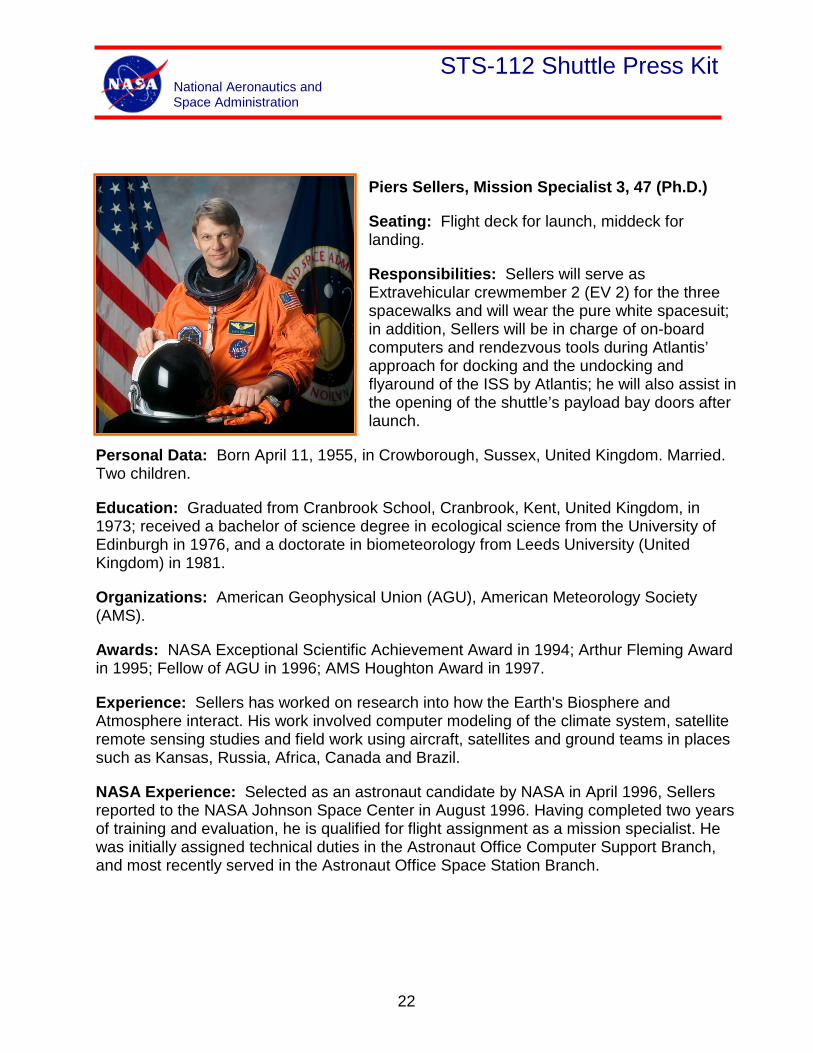
Piers Sellers, Mission Specialist 3, 47 (Ph.D.)
Seating: Flight deck for launch, middeck for landing.
Responsibilities: Sellers will serve as Extravehicular crewmember 2 (EV 2) for the three spacewalks and will wear the pure white spacesuit; in addition, Sellers will be in charge of on-board computers and rendezvous tools during Atlantis’ approach for docking and the undocking and flyaround of the ISS by Atlantis; he will also assist in the opening of the shuttle’s payload bay doors after launch.
Personal Data: Born April 11, 1955, in Crowborough, Sussex, United Kingdom. Married. Two children.
Education: Graduated from Cranbrook School, Cranbrook, Kent, United Kingdom, in 1973; received a bachelor of science degree in ecological science from the University of Edinburgh in 1976, and a doctorate in biometeorology from Leeds University (United Kingdom) in 1981.
Organizations: American Geophysical Union (AGU), American Meteorology Society (AMS).
Awards: NASA Exceptional Scientific Achievement Award in 1994; Arthur Fleming Award in 1995; Fellow of AGU in 1996; AMS Houghton Award in 1997.
Experience: Sellers has worked on research into how the Earth's Biosphere and Atmosphere interact. His work involved computer modeling of the climate system, satellite remote sensing studies and field work using aircraft, satellites and ground teams in places such as Kansas, Russia, Africa, Canada and Brazil.
NASA Experience: Selected as an astronaut candidate by NASA in April 1996, Sellers reported to the NASA Johnson Space Center in August 1996. Having completed two years of training and evaluation, he is qualified for flight assignment as a mission specialist. He was initially assigned technical duties in the Astronaut Office Computer Support Branch, and most recently served in the Astronaut Office Space Station Branch.
22
STS-112 Shuttle Press Kit National Aeronautics and Space Administration
Fyodor Yurchikhin, Mission Specialist 4, 43 (Ph.D., RSC-Energia)
Seating: Middeck for launch and landing.
Responsibilities: Yurchikhin will assist Melroy in the preparation of the spacewalk hardware for the three spacewalks by Wolf and Sellers; he will also assist Magnus in the transfer of water and payloads from Atlantis to the ISS during docked operations and will serve as an expert in Russian module systems on the ISS during the joint phase of the flight.
Personal Data: Born Jan. 3, 1959, in Batumi, Autonomous Republic of Ajara in Georgia. Married to Larisa Anatolievna
Yurshikina, born in Shyolkovo, Moscow region. They have two daughters. His father, Nikolai Fyodorovich Yurchikhin, and mother, Mikrula Sofoklevna Yurchikhina, reside in Sindos, Greece. He also has a brother, two years younger. Hobbies include collecting stamps and space logos, sports, history of cosmonautics, and promotion of space. He also enjoys reading history, science fiction and the classics.
Education: After graduation from high school in Batumi in 1976, he entered the Moscow Aviation Institute named after Sergey Ordzhonikidze. He finished studying in 1983, and is qualified as a mechanical engineer, specializing in airspace vehicles. In 2001, he graduated from the Moscow Service State University with a Ph.D. in economics.
Experience: After graduating from the S. Ordzhonikidze Moscow Aviation Institute, Yurchikhin worked at the Russian Space Corporation Energia from September 1983 until August 1997. He began working as a controller in the Russian Mission Control Center, and held the positions of engineer, senior engineer, and lead engineer, eventually becoming a lead engineer for Shuttle-Mir and NASA-Mir Programs.
In August 1997, he was enrolled in the RSC Energia cosmonaut detachment as a cosmonaut-candidate.
From January 1998 to November 1999, he completed his basic training course. In November 1999, he was qualified as a test cosmonaut. In January 2000, he started training in the test-cosmonaut group for the ISS Program.
23
STS-112 Shuttle Press Kit National Aeronautics and Space Administration
Rendezvous and Docking
Atlantis’ rendezvous and docking with the International Space Station begins with the precisely timed launch of the shuttle on a course for the station. During the first two days of the mission, periodic engine firings will gradually bring Atlantis to a point about 9½ statute miles behind the station, the starting point for a final approach to the station.
About 2½ hours before the scheduled docking time on Flight Day 3, Atlantis will reach that point, about 50,000 feet behind the ISS. There Atlantis' jets will be fired in a Terminal Intercept (TI) burn to begin the final phase of the rendezvous. Atlantis will close the final miles to the station during the next orbit.
As Atlantis closes in, the shuttle’s rendezvous radar system will begin tracking the station and providing range and closing rate information to the crew. During the final approach, Atlantis can do as many as four small mid-course corrections at regular intervals. Just after the fourth correction is completed, Atlantis will reach a point about half a mile below the station. There, about an hour before the scheduled docking, Commander Jeff Ashby will take over manual control of the approach.
Ashby will slow Atlantis' approach and fly to a point about 600 feet directly below the station, from which he will begin a quarter-circle of the ISS, slowly moving to a position in front of the complex, in line with its direction of travel. Pilot Pamela Melroy will help Ashby in controlling Atlantis' approach. Mission Specialist Dave Wolf also will play key roles in the rendezvous, using a handheld laser ranging device and operating the docking mechanism to latch the station and Atlantis together after the two spacecraft make contact. Mission Specialist Sandra Magnus will be backup on the docking system and Mission Specialist Piers Sellers will fill the backup role with the handheld laser ranging device.
24
STS-112 Shuttle Press Kit National Aeronautics and Space Administration
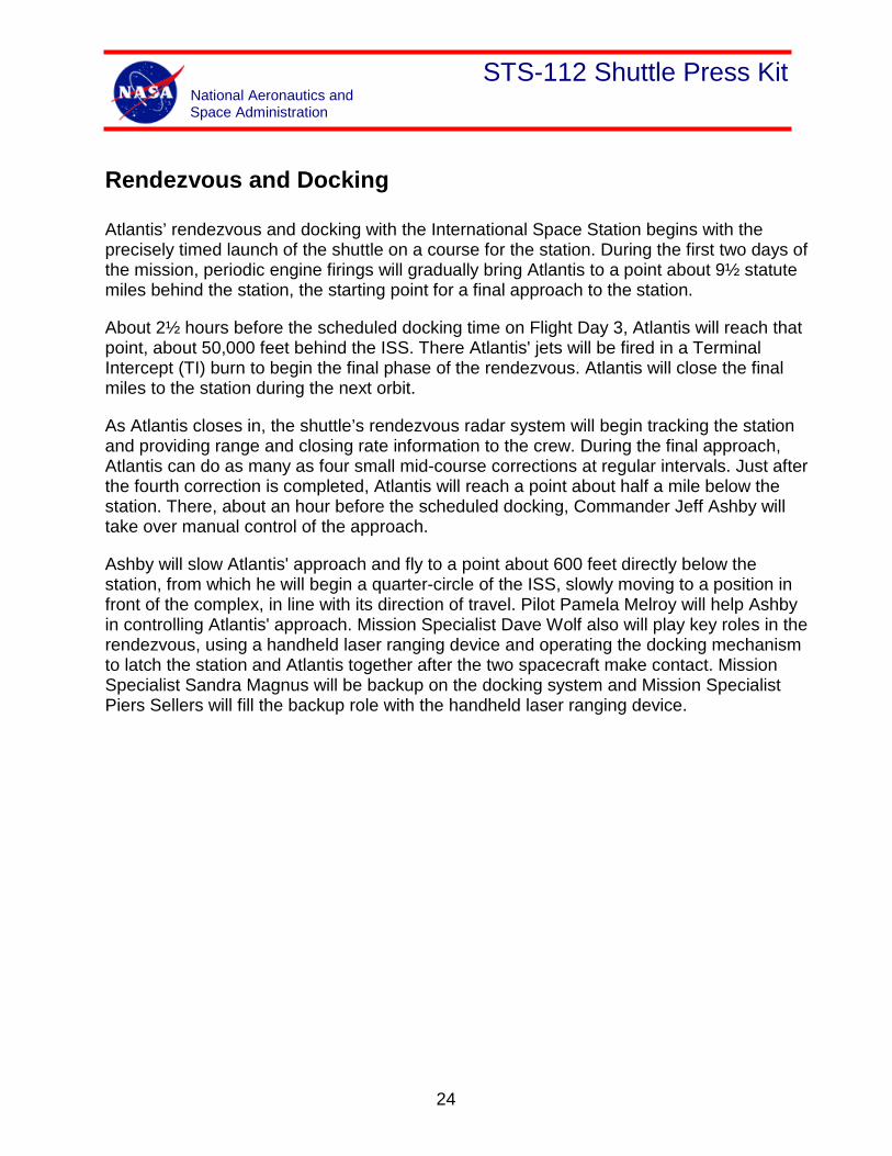
Ashby will fly the quarter-circle of the station while slowly closing in on the complex, stopping at a point a little more than 300 feet directly in front of the station. From there, he will begin slowly moving Atlantis toward the station at about a tenth of a mile per hour. Using a view from a camera mounted in the center of Atlantis' docking mechanism as a key alignment aid, Ashby will precisely center the docking ports of the two spacecraft. Ashby will fly to a point where the docking mechanisms are 30 feet apart, and pause to check the alignment.
For Atlantis' docking, Ashby will maintain the shuttle's speed relative to the station at about one-tenth of a foot per second (though both spacecraft are traveling at about 17,500 mph), and keep the docking mechanisms aligned to within a tolerance of three inches. When Atlantis makes contact with the station, preliminary latches will automatically attach the two spacecraft. Immediately after Atlantis docks, the shuttle's steering jets will be deactivated to reduce the forces acting at the docking interface. Shock absorber-type springs in the docking mechanism will dampen any relative motion between the shuttle and the station.
25
STS-112 Shuttle Press Kit National Aeronautics and Space Administration
Once that motion between the spacecraft has been stopped, Wolf will secure the docking mechanism, sending commands for Atlantis' docking ring to retract and to close a final set of latches between the shuttle and station.
Undocking, Separation and Flyaround
Once Atlantis is ready to undock, Wolf will send a command to release the docking mechanism. At initial separation of the spacecraft, springs in the docking mechanism will gently push the shuttle away from the station. Atlantis’ steering jets will be shut off to avoid any inadvertent firings during this initial separation.
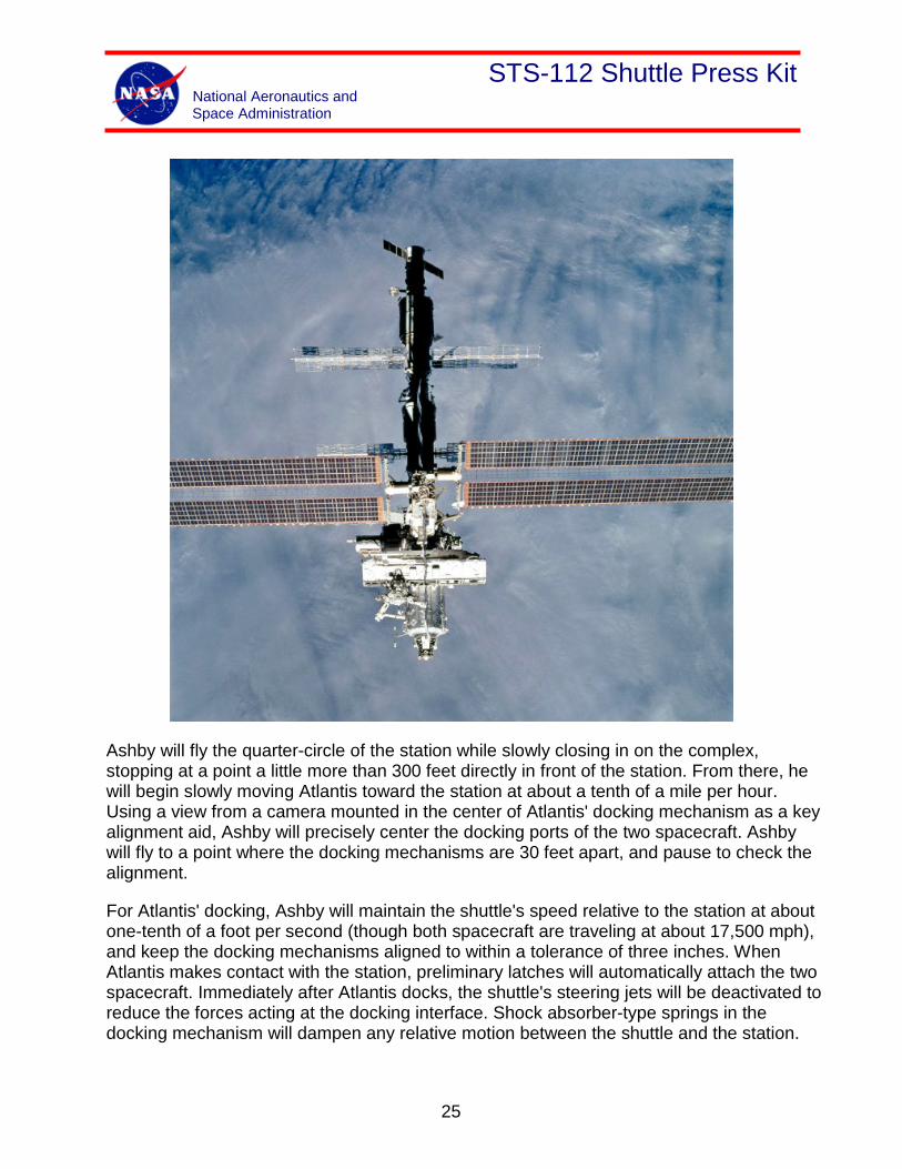
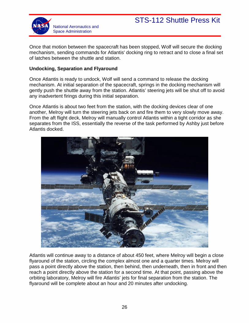
Once Atlantis is about two feet from the station, with the docking devices clear of one another, Melroy will turn the steering jets back on and fire them to very slowly move away. From the aft flight deck, Melroy will manually control Atlantis within a tight corridor as she separates from the ISS, essentially the reverse of the task performed by Ashby just before Atlantis docked.
Atlantis will continue away to a distance of about 450 feet, where Melroy will begin a close flyaround of the station, circling the complex almost one and a quarter times. Melroy will pass a point directly above the station, then behind, then underneath, then in front and then reach a point directly above the station for a second time. At that point, passing above the orbiting laboratory, Melroy will fire Atlantis’ jets for final separation from the station. The flyaround will be complete about an hour and 20 minutes after undocking.
26
STS-112 Shuttle Press Kit National Aeronautics and Space Administration
Spacewalks
STS-112 Extravehicular Activity
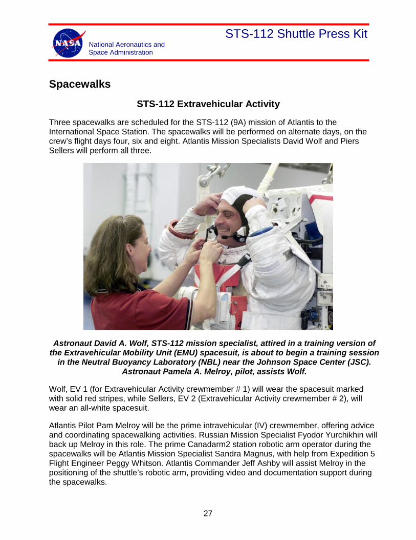
Three spacewalks are scheduled for the STS-112 (9A) mission of Atlantis to the International Space Station. The spacewalks will be performed on alternate days, on the crew’s flight days four, six and eight. Atlantis Mission Specialists David Wolf and Piers Sellers will perform all three.
Astronaut David A. Wolf, STS-112 mission specialist, attired in a training version of the Extravehicular Mobility Unit (EMU) spacesuit, is about to begin a training session
in the Neutral Buoyancy Laboratory (NBL) near the Johnson Space Center (JSC). Astronaut Pamela A. Melroy, pilot, assists Wolf.
Wolf, EV 1 (for Extravehicular Activity crewmember # 1) will wear the spacesuit marked with solid red stripes, while Sellers, EV 2 (Extravehicular Activity crewmember # 2), will wear an all-white spacesuit.
Atlantis Pilot Pam Melroy will be the prime intravehicular (IV) crewmember, offering advice and coordinating spacewalking activities. Russian Mission Specialist Fyodor Yurchikhin will back up Melroy in this role. The prime Canadarm2 station robotic arm operator during the spacewalks will be Atlantis Mission Specialist Sandra Magnus, with help from Expedition 5 Flight Engineer Peggy Whitson. Atlantis Commander Jeff Ashby will assist Melroy in the positioning of the shuttle’s robotic arm, providing video and documentation support during the spacewalks.
27
STS-112 Shuttle Press Kit National Aeronautics and Space Administration
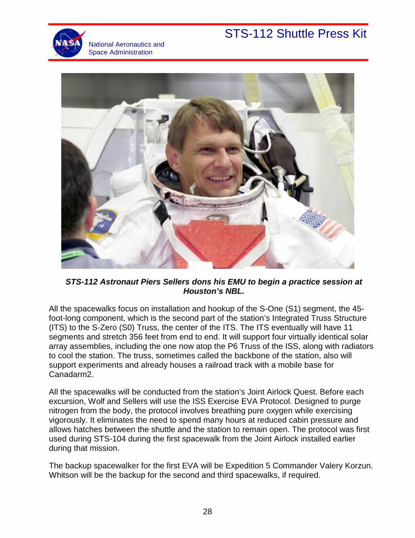
STS-112 Astronaut Piers Sellers dons his EMU to begin a practice session at Houston’s NBL.
All the spacewalks focus on installation and hookup of the S-One (S1) segment, the 45-foot-long component, which is the second part of the station’s Integrated Truss Structure (ITS) to the S-Zero (S0) Truss, the center of the ITS. The ITS eventually will have 11 segments and stretch 356 feet from end to end. It will support four virtually identical solar array assemblies, including the one now atop the P6 Truss of the ISS, along with radiators to cool the station. The truss, sometimes called the backbone of the station, also will support experiments and already houses a railroad track with a mobile base for Canadarm2.
All the spacewalks will be conducted from the station’s Joint Airlock Quest. Before each excursion, Wolf and Sellers will use the ISS Exercise EVA Protocol. Designed to purge nitrogen from the body, the protocol involves breathing pure oxygen while exercising vigorously. It eliminates the need to spend many hours at reduced cabin pressure and allows hatches between the shuttle and the station to remain open. The protocol was first used during STS-104 during the first spacewalk from the Joint Airlock installed earlier during that mission.
The backup spacewalker for the first EVA will be Expedition 5 Commander Valery Korzun. Whitson will be the backup for the second and third spacewalks, if required.
28
STS-112 Shuttle Press Kit National Aeronautics and Space Administration
Spacewalk No. 1, Flight Day Four: Connect power, data and fluid umbilicals between S0 and S1, release radiator beam launch locks, deploy the S-Band Antenna Support Assembly, release launch restraints on the Crew and Equipment Translation Aid and install the first of two External TV Camera Groups.
Before Wolf and Sellers emerge from the airlock, Magnus and Whitson will use the station’s robotic arm to grapple S1, remove it from Atlantis’ cargo bay and move it to the end of S0. After a claw and then bolts attach the ends of the two segments, Wolf and Sellers will emerge from the Joint Airlock and begin setting up for the first spacewalk.
Toward the end of that process, Wolf will attach and enter a foot restraint on the end of the station’s Canadarm2. Magnus will maneuver him to the cable tray atop S1. Once he is clear, Sellers will move to the forward side of S1, where he will release the five radiator launch locks nearest the S0 connection.
Meanwhile, Wolf will open thermal covers over cable trays atop S0 and S1, then demate connectors on the S0 side from temporary attachment points and connect their free ends to receptacles on S1. Sellers will open a circuit breaker, then close it once Wolf completes those connections.
After those 50-minute tasks, Wolf and Sellers will collaborate to deploy the S-Band Antenna Support Assembly (SASA). That task is expected to take about an hour and 15 minutes. The new component will increase the S-band data and voice communications capability from the ISS to ground controllers.
Wolf, at the end of Canadarm2, will be maneuvered to SASA’s launch position at the center of truss between the two keel pin assemblies of S1. There he will use a Pistol Grip Tool (PGT) to release four launch bolts and two mast bolts. He and Sellers will remove the SASA from its launch position and Wolf will carry it, while Magnus maneuvers him on the arm to the installation site near the inboard end of S1. Sellers, meanwhile, will move to the installation site and release two clamps.
Wolf will soft dock the SASA to its support bracket, then tighten a stanchion bolt about nine turns until it drops out of its launch position. Still using the PGT, he will tighten that bolt about 21 more turns until it reaches a hard stop, completing the SASA physical installation.
The next task for Wolf is to demate the ends of four connectors and install them to provide power and data links to the SASA. Sellers will then remove a shroud covering the antenna, bundle it and temporally stow it. Finally, Wolf will release four SASA gimbal locks with the PGT and rotate them away from SASA’s high-gain antenna. Then Sellers will hand Wolf the shroud bundle, and Wolf will take it with him on the arm to the launch position of the Crew and Equipment Translation Aid (CETA).
29
STS-112 Shuttle Press Kit National Aeronautics and Space Administration
The CETA is a kind of handcar for the truss’ rail line, with which spacewalkers eventually will be able to push themselves and equipment along much of the 356-foot length of the completed main truss.
Wolf will release a brake shaft launch lock with the PGT and then use it to release two portside brake handle launch clamp bolts. He will deploy dynamic and parking brake handles and lock sliders. That complete, he will release four bolts that will free two portside launch handle brackets, and put the brackets in a trash bag.
After setting the CETA parking brake, Wolf will turn his attention to its main launch bolts. He will release four scissor bolts, break the torque on four launch restraint bolts and fully release four others, stowing them in the trash bag. Then he will release the CETA parking brake and push it along its rails to a point near the center of S0. There he will repeat the portside work on CETA’s starboard side.
During Wolf’s 75-minute CETA activity, Sellers will first release three more radiator beam launch locks on the new S1 truss. Then he will demate the ends of a total of nine power, video and data cables from their temporary positions on S0 and mate them to receptacles on S1.
Installation of the S1’s outboard nadir external camera will occupy Wolf and Sellers for about the next hour and 15 minutes. Wolf will remove the camera, launched on Atlantis’ middeck, and the tilt pad cover from the camera’s light before taking the camera from its large bag. He will then maneuver with the assembly to the starboard keel, where he will attach the assembly, driving its center jacking bolt about 28 turns with a PGT.
Wolf will next release two camera stanchion launch restraint bolts, then slide the camera out of its keel interface and move it to its installation location. With a PGT he will tighten a stanchion bolt about nine turns until it drops out of its launch position, then tighten it about another 21 turns until it reaches a hard stop.
The spacewalkers will then mate eight connectors to take power, data and images to and from the camera. Wolf and Sellers then will temporarily remove the camera so they can install four more connectors. Wolf will reinstall it using the PGT to tighten its center-jacking bolt about 28 turns.
Near the end of the first spacewalk, Wolf will connect a series of cables linking S0 and S1 on the Utilities Nadir Tray. The spacewalkers each will release five Radiator Beam Launch Locks.
After about half an hour of EVA cleanup the spacewalkers will re-enter the airlock.
30
STS-112 Shuttle Press Kit National Aeronautics and Space Administration
Spacewalk No. 2, Flight Day Six: Install Lab Camera, install Spool Positioning Devices (SPDs), release CETA launch locks, connect Ammonia Tank Assembly (ATA) umbilicals and release radiator beam launch locks.
For the second of the three spacewalks, Sellers will ride at the end of the arm and Wolf will free-float. After about half an hour for setup after leaving the airlock, Sellers will ride the arm to a position near the left side of the Z1 truss and its junction with the U.S. laboratory Destiny. Wolf will make his way to the aft side of the Z1-P6 truss junction.
There, both astronauts will remove insulation covers on booties covering quick disconnect (QD) fittings in ammonia lines, part of the station’s thermal cooling systems. Sellers will install two one-inch “spool positioning devices” (SPDs) to better match the position of the bodies of two QDs at the base of the Z1 truss while Wolf will conduct a similar task at the Z1-P6 truss interface.
The installation involves rotating the QD locking collar to the unlock position, attaching a circular section of the SPD to the QD, then adding a clamp-like device to tension it there before finally checking the SPD installation and performing a pull test on the QD. Wolf is to spend 45 minutes on that task, Sellers 30 minutes.
Next, Wolf will maneuver to the CETA cart, where he will spend about 25 minutes releasing the starboard brake system as well as the swing arm and coupler restraints.
Sellers, meanwhile, will ride the arm to the ammonia tank assembly at the inboard end of S1. There he will demate two dustcaps and install the ends of two umbilicals on the Ammonia Tank Assembly (ATA). The umblicials on the Nitrogen Tank Assembly (NTA) on the outboard side of S0 are attached there with QDs, which he will use to make the new connection. He will reinstall the dustcaps he removed from the ATA on the fittings that held the QDs on the NTA.
The next task is a repeat of the camera group installation on the first spacewalk, involving both Wolf and Sellers. This installation, however, will be on the U.S. laboratory Destiny. Installation steps are virtually identical, though the players are reversed with Sellers still affixed at the end of the arm.
With the camera installation complete, Sellers will leave the arm’s foot restraint and move to the CETA light stanchion to retrieve a bag of SPDs, then move to the starboard camera group he and Wolf installed two days before to temporarily stow the bag. Then he will move to the inboard end of S1 where he will begin installing SPDs on one-inch ammonia lines on Radiator Beam Valve Module (RBVM) No. 1.
The RBVM allows or prevents transfer of ammonia supply or return to or from the Radiator ORU, allows remote controlled venting of the radiator fluid loop for replacement of the Radiator ORU, and provides automatic pressure relief when the Radiator ORU is over pressurized. The RBVM also measures pressure and temperature of the fluid line, provides
31
STS-112 Shuttle Press Kit National Aeronautics and Space Administration
temperature measurements of Radiator ORU environment, provides instrumentation monitoring data, and receives valve actuation command data. There are 12 RBVMs on the space station. Each measures 17 in. x 27 in. x 6 in. and weighs 56 lbs.
Meanwhile, Wolf will replace Sellers on the arm foot restraint. Magnus will move him to the CETA light station where he will pick up his own SPD bag, then maneuver to the outboard end of S1. There, he will begin installing SPDs on one-inch ammonia line QDs at RBVM No. 6.
The two spacewalkers will install a total of 24 SPDs during this 2¼-hour task.
The last task scheduled for the second spacewalk is releasing Radiator Beam Launch Locks. Both Wolf and Sellers will use pistol grip tools to release the launch locks, turning each of three bolts 60 to 62 rotations. The task is scheduled for 15 minutes.
A 30-minute cleanup period will wrap up the spacewalk, with the two astronauts entering the Joint Airlock and repressurizing it to end the EVA.
Spacewalk No. 3, Flight Day 8: Interface Umbilical Assembly (IUA) removal and replacement, fluid jumper installation, drag link/keel pin removal, Thermal Radiator Rotary Joint (TRRJ) SPD installation, S1/S3 line clamps and Segment to Segment Attachment System (SSAS) ready to latch test, and Squib Firing Unit (SFU) reconfiguration.
After the 30-minute setup period, the first job on the flight’s final spacewalk is removal and replacement of the Interface Umbilical Assembly (IUA). The IUA is installed with the Trailing Umbilical System (TUS) on the Mobil Transporter (MT), the railcar that supports the base for the station’s robotic arm.
The TUS incorporates a reel for the trailing umbilical, a power and data cable linking the station and the MT as it moves along the tracks on the truss. Program officials decided to replace the IUA after a bolt securing a backup cable cutter could not be removed during its initial installation on the STS-110 mission last April.
Wolf and Sellers will move from the airlock to the MT, on the tracks of S0. They first will remove the TUS cable, with Sellers keeping it under tension while being careful not to bend or crimp it. Wolf will loosen three cable connections, then remove the cable cutter before temporarily stowing the TUS cable.
To remove the IUA itself, Wolf detaches four cable connections linking it to the MT. Then Sellers, using a pistol grip tool, removes four bolts attaching the IUA assembly to the MT. Finally he removes the IUA from its “soft dock” connection and hands it to Wolf.
32
STS-112 Shuttle Press Kit National Aeronautics and Space Administration
Installation of the new IUA is basically the same operation in reverse, with Sellers soft docking the new unit and attaching it to the MT with four bolts. Wolf then makes the seven connections between the IUA, the MT and the TUS.
Wolf and Sellers move to a point at the junction of S0 and S1 for the next activity, a one-hour, 25-minute installation of fluid jumpers to enable ammonia coolant to flow between the two truss segments. Sellers releases two jumpers on S0, then moves into the Canadarm2 foot restraint for a ride to the jumper install position at the lower segment-to-segment utility carrier. There he will join Wolf, waiting nearby in a portable foot restraint.
Wolf will mate and install SPDs on two jumper connections on the S0 side, while Sellers performs a similar task on the S1 side. Each connection will involve a pull test and a three-minute leak check. Wolf reinstalls thermal covers while Sellers closes S1 and S0 utility tray shrouds. Then Sellers, still on the arm, and Wolf, move on to S1’s port drag link.
They will work together to release that drag link, a large metal rod used as a launch restraint. Wolf will release a bolt attaching the drag link to the keel, while Sellers releases a similar bolt attaching the drag link to S1. Sellers takes the drag link to its stowage location on the S1 framework and attaches it.
While Sellers attaches the drag link, Wolf moves to the port keel pin, another launch support device, first tightening two keel scissor bolts, then releasing two keel pin bolts and rotating keel pin latches free. Once rotated Wolf reinstalls the bolt, removes two pit-pins. Sellers reinstalls the keel pin a nearby.
The processes are repeated on the S1 starboard drag link and keel pin.
Wolf and Sellers, now off the arm, will move to the CETA handrail cart where each will take a 1½ -inch SPD to be installed on ammonia lines near a Thermal Radiator Rotary Joint on S0. Wolf will release bolts securing that joint in its launch position.
The last task is to perform a test of the Segment-to-Segment Attachment System (SSAS) at the outboard end of S1. The SSAS there consists of a remotely operated claw and three motorized bolt assemblies. Wolf will depress ready to latch indicators on each for several seconds. This will verify the readiness of the S1 segment to receive other starboard truss components on future flights.
Finally, while Wolf does the SSAS test, Sellers will reconfigure the Squib Firing Unit (SFU) power connector. The SFU is used to release radiator panels for deployment.
A final 30-minute cleanup period will precede the entry of both spacewalkers into the airlock and its repressurization to complete the mission’s final spacewalk.
*************
33
STS-112 Shuttle Press Kit National Aeronautics and Space Administration
Thermal Radiator Rotary Joint
The Thermal Radiator Rotary Joint (TRRJ) Orbital Replacement Unit (ORU) provides mechanical and electrical energy for rotating the ISS heat rejection radiators for varying heat rejection rates responding to system requirements. The TRRJ rotational capabilities are controlled by the Rotary Joint Motor Controllers (RJMC), which also power the Drive Lock Assemblies (DLA). The RJMC receives signal control from the rotary joint MDMs. The TRRJ is installed into the S1 and P1 truss segments before launch on Flights 9A and 11A.
Key Data:
Size: 3.4 ft. x 4.5 ft. x 5.2 ft.
Weight: 992 lb
Number on space station: 2
Components: Primary structure is made of aluminum and the drive and rotational elements are steel; the flex hoses are corrugated corrosion resistant steel interfacing with corrosion resistant steel tubing and aluminum quick disconnects. Primary structure includes a Flex Hose Rotary Coupler, the Bearing Assay, the DLA and RJMC. There are EVA handholds to assist in EVA operations for electrical and fluid interconnects during on-orbit assembly.
34
STS-112 Shuttle Press Kit National Aeronautics and Space Administration
Payload Overview
The primary cargo element to be delivered on Mission 9A is the second truss segment, Starboard 1 (S1), of the main International Space Station Integrated Truss Structure (ITS). The ITS will eventually be used to support the four power-generating Photo-Voltaic Modules (PVMs) of the ISS, the permanent External Active Thermal Control Subsystem (EATCS). The ITS will also provide a translation path for the Mobile Servicing System (MSS) along specially designed truss rails. The truss rails allow the Space Station Remote Manipulator System (SSRMS) to be positioned at various locations along the truss for performing maintenance tasks, element installations, and providing EVA assistance.
Integrated within the S1 truss segment are various hardware components and their associated cabling for powering and controlling the starboard side systems of the ITS. S1 contains almost all of the hardware components for Loop A of the EATCS, which will be activated during Mission 12A.1 to replace the Early External Active Thermal Control Subsystem (EEATCS). Once operational, the EATCS will provide a permanent system of thermal control for all U.S. On-Orbit Segment Internal Active Thermal Control Subsystem (IATCS) water loops and a number of external truss avionics. The EATCS equipment on S1 includes a Pump Module (PM) Assembly, an Ammonia Tank Assembly (ATA), a Nitrogen Tank Assembly (NTA), three radiator Orbital Replacement Units (ORUs), six Radiator Beam Valve Modules (RBVMs), a Thermal Radiator Rotary Joint (TRRJ), and numerous ammonia fluid lines, junction boxes, heaters and coldplates.
35
STS-112 Shuttle Press Kit National Aeronautics and Space Administration
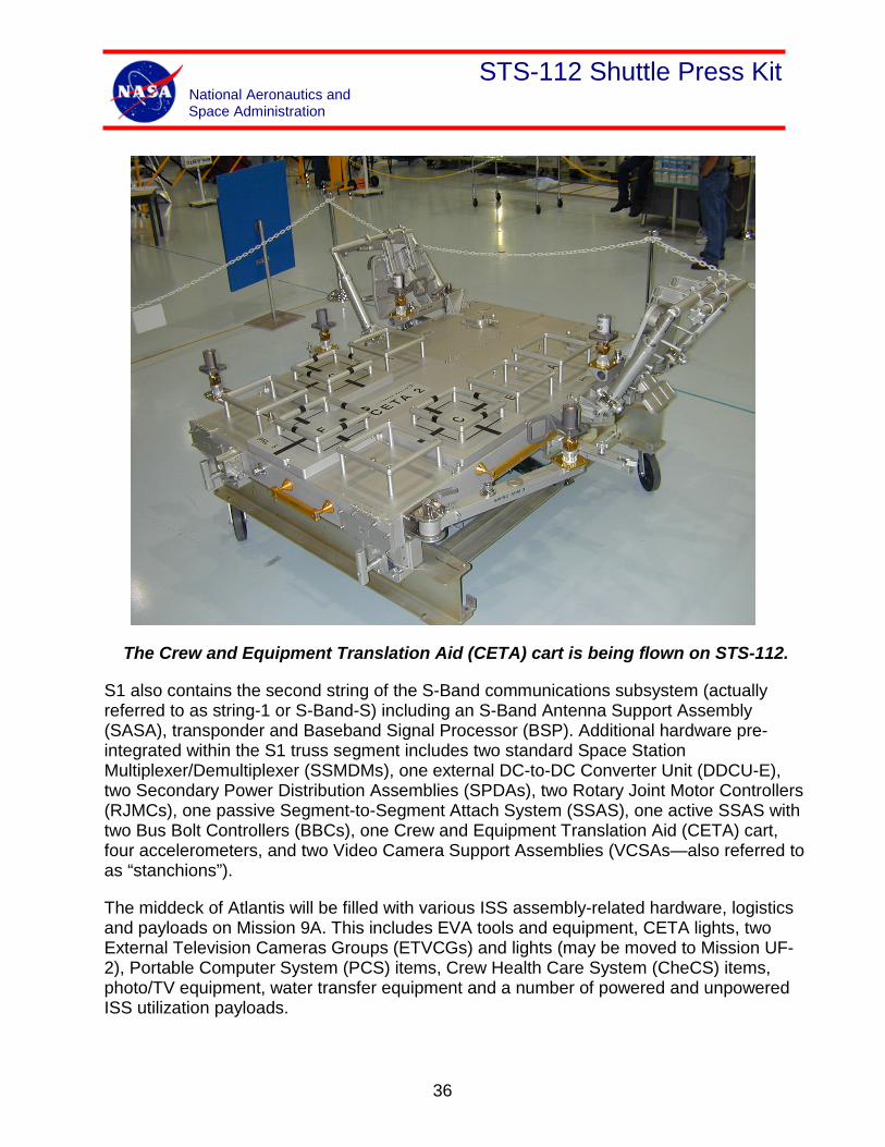
The Crew and Equipment Translation Aid (CETA) cart is being flown on STS-112.
S1 also contains the second string of the S-Band communications subsystem (actually referred to as string-1 or S-Band-S) including an S-Band Antenna Support Assembly (SASA), transponder and Baseband Signal Processor (BSP). Additional hardware pre-integrated within the S1 truss segment includes two standard Space Station Multiplexer/Demultiplexer (SSMDMs), one external DC-to-DC Converter Unit (DDCU-E), two Secondary Power Distribution Assemblies (SPDAs), two Rotary Joint Motor Controllers (RJMCs), one passive Segment-to-Segment Attach System (SSAS), one active SSAS with two Bus Bolt Controllers (BBCs), one Crew and Equipment Translation Aid (CETA) cart, four accelerometers, and two Video Camera Support Assemblies (VCSAs—also referred to as “stanchions”).
The middeck of Atlantis will be filled with various ISS assembly-related hardware, logistics and payloads on Mission 9A. This includes EVA tools and equipment, CETA lights, two External Television Cameras Groups (ETVCGs) and lights (may be moved to Mission UF-2), Portable Computer System (PCS) items, Crew Health Care System (CheCS) items, photo/TV equipment, water transfer equipment and a number of powered and unpowered ISS utilization payloads.
36
STS-112 Shuttle Press Kit National Aeronautics and Space Administration
Unpowered ISS utilization payloads launched on Mission 9A (ascent) will include:
• Plant Generic Bioprocessing Apparatus—Stowage (PGBA-S)
• PGBA Muffler
• Two Cellular Biotechnology Operating Science System (CBOSS) Cryodewars (StelSys Experiment)
• Human Research Facility Resupply (HRF-Res)
• Zeolite Crystal Growth—Sample Stowage (ZCG-SS)
Powered ISS utilization payloads launched on Mission 9A (ascent) will include:
• Commercial Generic Bioprocessing Apparatus (CGBA)
• PGBA
• Protein Crystal Growth Single-locker Thermal Enclosure System-7 (PCG-STES-7)
Unpowered ISS utilization payloads returning on Mission 9A (descent) will include:
• EarthKAM—Experiment Unique Equipment (EarthKAM-EUE)
• Advanced Astroculture—Growth Chamber (ADVASC-GC)
• ADVASC—Sample (ADVASC-S2D)
• ADVASC—Sample (ADVASC-S3D)
• ZCG—SS
• HRF—Increment 4 samples/data
• Microencapsulation Electrostatic Processing System (MEPS-S10)
• ZCG—Stowage
• Two CBOSS Cryodewars (StelSys Experiment)
Powered ISS utilization payloads returning on Mission 9A (descent) will include:
• PCG-STES-9
• PCG-STES-10
37
STS-112 Shuttle Press Kit National Aeronautics and Space Administration
Secondary Payloads
The Spatial Heterodyne Imager for Mesospheric Radicals (SHIMMER) consists of a telescope, interferometer, imaging optics, and Charge Coupled Device (CCD) camera all housed in a single enclosure. The SHIMMER will be used to evaluate a powerful new technique for Ultraviolet (UV) remote sensing referred to as Spatial Heterodyne Spectroscopy (SHS). The SHIMMER instrument will make global maps of the vertical density distribution of the atmospheric trace gas hydroxyl (OH) in the altitude region between 40 and 90 km. The SHIMMER hardware is stowed in two standard middeck lockers for launch and entry and is removed for on-orbit operations. The SHIMMER will be mounted to the orbiter side hatch window during on-orbit operations using a payload-provided mounting bracket and light baffle.
Payloads of Opportunity
The objective of the Ram Burn Observation (RAMBO) payload is to help calibrate the RAMBO satellite. This requires retrograde, posigrade, and out-of-place burns. The location of the RAMBO satellite is classified.
38
STS-112 Shuttle Press Kit National Aeronautics and Space Administration
S1 Truss Extends International Space Station Backbone
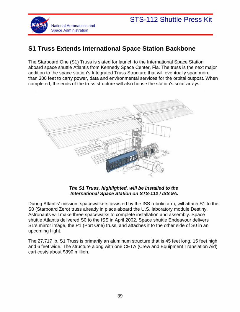
The Starboard One (S1) Truss is slated for launch to the International Space Station aboard space shuttle Atlantis from Kennedy Space Center, Fla. The truss is the next major addition to the space station’s Integrated Truss Structure that will eventually span more than 300 feet to carry power, data and environmental services for the orbital outpost. When completed, the ends of the truss structure will also house the station’s solar arrays.
The S1 Truss, highlighted, will be installed to the International Space Station on STS-112 / ISS 9A.
During Atlantis’ mission, spacewalkers assisted by the ISS robotic arm, will attach S1 to the S0 (Starboard Zero) truss already in place aboard the U.S. laboratory module Destiny. Astronauts will make three spacewalks to complete installation and assembly. Space shuttle Atlantis delivered S0 to the ISS in April 2002. Space shuttle Endeavour delivers S1’s mirror image, the P1 (Port One) truss, and attaches it to the other side of S0 in an upcoming flight.
The 27,717 lb. S1 Truss is primarily an aluminum structure that is 45 feet long, 15 feet high and 6 feet wide. The structure along with one CETA (Crew and Equipment Translation Aid) cart costs about $390 million.
39
STS-112 Shuttle Press Kit National Aeronautics and Space Administration
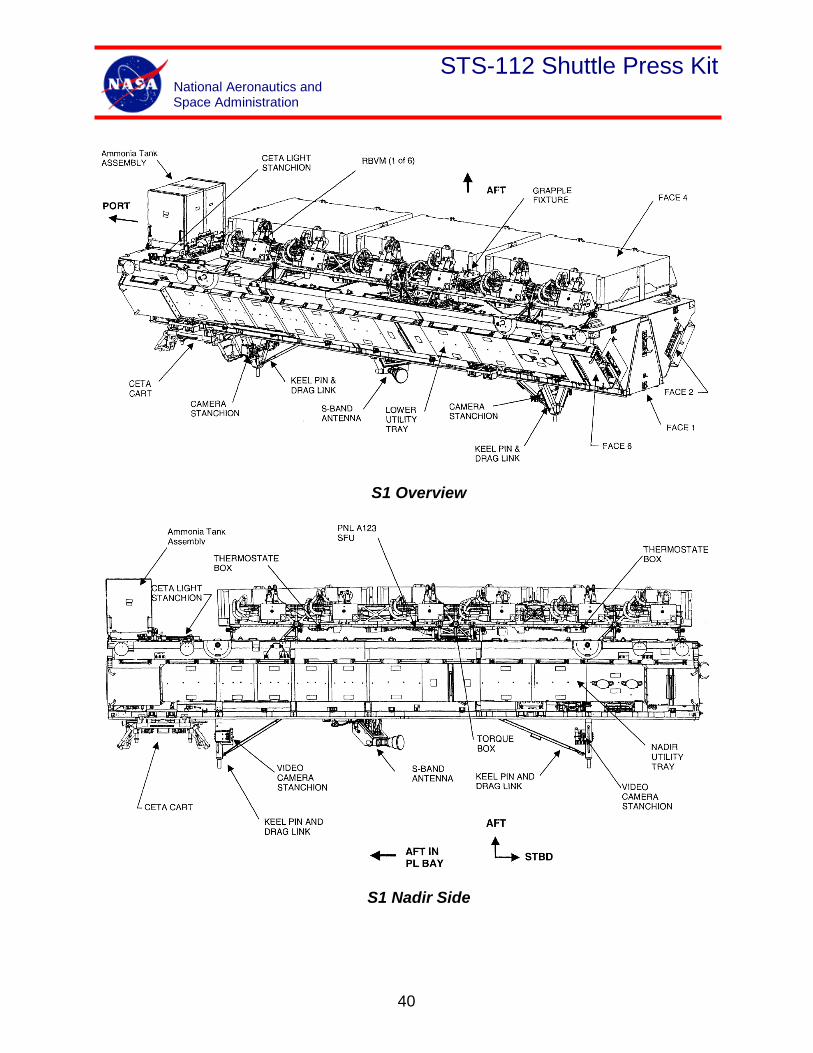
S1 Overview
S1 Nadir Side
40
STS-112 Shuttle Press Kit National Aeronautics and Space Administration
Boeing began construction of the truss in May 1998 in Huntington Beach, Calif., and completed the work in Huntsville, Ala., in March 1999. The S1 moved to Kennedy Space Center, Fla., in October 1999 for flight processing. Boeing delivered the S1 to NASA in June 2002 for final preparations and preflight checks.
Both S1 and eventually P1 provide structural support for the Active Thermal Control System, the Mobile Transporter, a CETA cart and antennas. The S1 has an S-band system; the P1 a UHF system. Both trusses also have mounts for cameras and lights.
Additionally, both S1 and P1 carry one radiator each as part of the space station’s cooling and heating system. The radiators are deployed in orbit and use 99.9 percent pure ammonia. The radiator assembly also rotates to keep itself in the shade and away from the sun. Each radiator has 18 launch locks securing the assembly during launch. The locks will be removed during a spacewalk before deploying the radiators.
The addition of S1 also extends the Mobile Transporter (MT) rail line. The MT car travels along the length of the truss structure and carries spacewalkers, tools, construction items and the space station robotic arm. Flying aboard S1 is one of two CETA carts that move spacewalkers along the MT rails to worksites along the truss structure. The cart is manually operated by a spacewalker and can also be used as a work platform. S1 and P1 carry one cart each.
The P1 Truss differs slightly from S1 and could be considered a mirror image. It has the same capabilities as the S1 except that P1 carries a UHF antenna. The P1 also carries a second CETA cart.
41
STS-112 Shuttle Press Kit National Aeronautics and Space Administration
International Space Station S1 and P1 Truss Summary
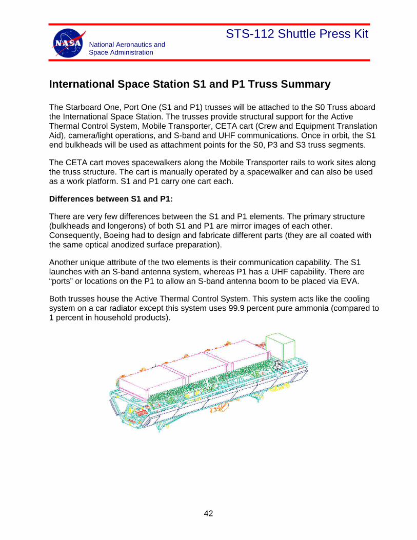
The Starboard One, Port One (S1 and P1) trusses will be attached to the S0 Truss aboard the International Space Station. The trusses provide structural support for the Active Thermal Control System, Mobile Transporter, CETA cart (Crew and Equipment Translation Aid), camera/light operations, and S-band and UHF communications. Once in orbit, the S1 end bulkheads will be used as attachment points for the S0, P3 and S3 truss segments.
The CETA cart moves spacewalkers along the Mobile Transporter rails to work sites along the truss structure. The cart is manually operated by a spacewalker and can also be used as a work platform. S1 and P1 carry one cart each.
Differences between S1 and P1:
There are very few differences between the S1 and P1 elements. The primary structure (bulkheads and longerons) of both S1 and P1 are mirror images of each other. Consequently, Boeing had to design and fabricate different parts (they are all coated with the same optical anodized surface preparation).
Another unique attribute of the two elements is their communication capability. The S1 launches with an S-band antenna system, whereas P1 has a UHF capability. There are “ports” or locations on the P1 to allow an S-band antenna boom to be placed via EVA.
Both trusses house the Active Thermal Control System. This system acts like the cooling system on a car radiator except this system uses 99.9 percent pure ammonia (compared to 1 percent in household products).
42
STS-112 Shuttle Press Kit National Aeronautics and Space Administration
Facts in brief:
• Manufacturer: Boeing
• Dimensions: 45 ft. x 15 ft. x 6 ft.
• Weight: 27,717 lbs. (S1); 30,871 lbs. (P1)
• Cost: $390 million each (one CETA cart launched on each truss element)
• Structure: Primarily aluminum
• Major components: Primary structure is made of aluminum and includes seven bulkheads per segment, four longerons per segment, heat transport subsystem, radiator support beam(s), trailing umbilical system, on-orbit video camera, electrical equipment, S-band antenna support equipment
• Purpose: To carry power, data and environmental services along the integrated truss structure. Also to provide active thermal protection to electrical components throughout the station.
• Construction: Started assembly at Boeing plant in Huntington Beach, Calif., in May 1998; moved to Boeing facility in Huntsville, Ala., in March 1999 for completion and then to Boeing Florida Operations at Kennedy Space Center, Fla., in October 1999 for flight processing. S1 handed off to NASA in June 2002.
• Major subcontractors: Lockheed Martin, Honeywell, Allied Signal, Hamilton Standard and ITT Cannon.
• Installation: S1 to be installed during mission STS-112/9A, P1 to be installed during STS-113/11A.
• Radiator assembly: The entire radiator beam assembly (upper portion of the elements) rotates to keep the radiators in the shade. There are 18 launch locks that keep this radiator beam assembly together during launch – all removed/stowed by EVA (special training for astronaut Piers Sellers on flight 9A).
43
STS-112 Shuttle Press Kit National Aeronautics and Space Administration
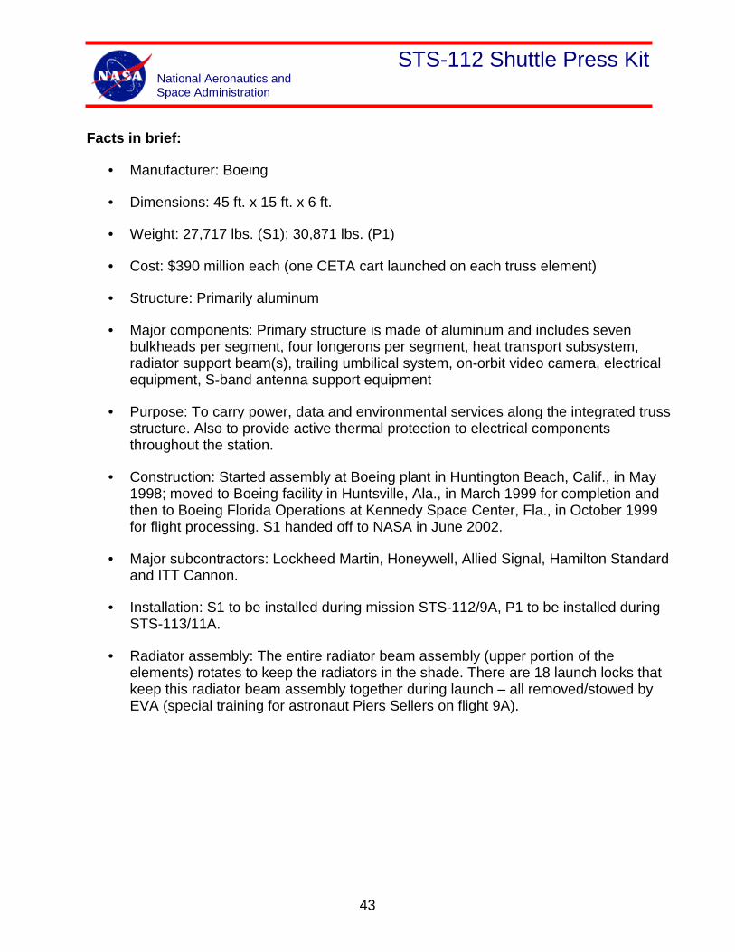
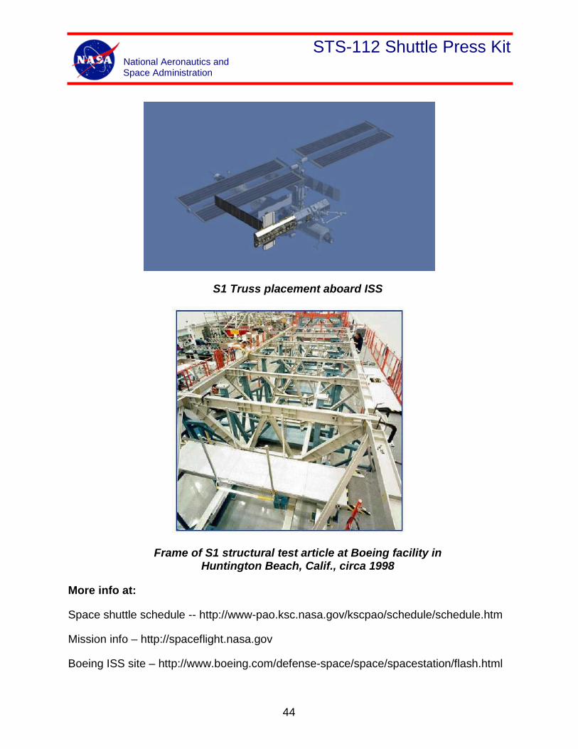
S1 Truss placement aboard ISS
Frame of S1 structural test article at Boeing facility in Huntington Beach, Calif., circa 1998
More info at:
Space shuttle schedule -- http://www-pao.ksc.nasa.gov/kscpao/schedule/schedule.htm
Mission info – http://spaceflight.nasa.gov
Boeing ISS site – http://www.boeing.com/defense-space/space/spacestation/flash.html
44
STS-112 Shuttle Press Kit National Aeronautics and Space Administration
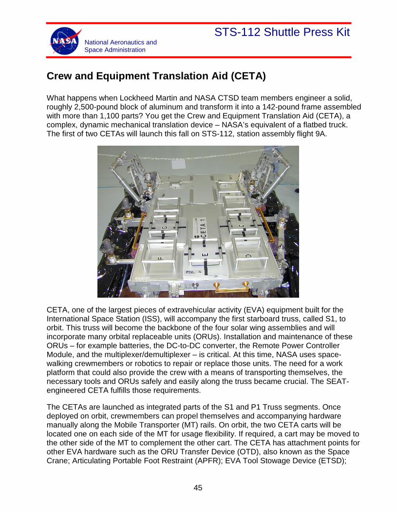
Crew and Equipment Translation Aid (CETA)
What happens when Lockheed Martin and NASA CTSD team members engineer a solid, roughly 2,500-pound block of aluminum and transform it into a 142-pound frame assembled with more than 1,100 parts? You get the Crew and Equipment Translation Aid (CETA), a complex, dynamic mechanical translation device – NASA’s equivalent of a flatbed truck. The first of two CETAs will launch this fall on STS-112, station assembly flight 9A.
CETA, one of the largest pieces of extravehicular activity (EVA) equipment built for the International Space Station (ISS), will accompany the first starboard truss, called S1, to orbit. This truss will become the backbone of the four solar wing assemblies and will incorporate many orbital replaceable units (ORUs). Installation and maintenance of these ORUs – for example batteries, the DC-to-DC converter, the Remote Power Controller Module, and the multiplexer/demultiplexer – is critical. At this time, NASA uses space-walking crewmembers or robotics to repair or replace those units. The need for a work platform that could also provide the crew with a means of transporting themselves, the necessary tools and ORUs safely and easily along the truss became crucial. The SEAT-engineered CETA fulfills those requirements.
The CETAs are launched as integrated parts of the S1 and P1 Truss segments. Once deployed on orbit, crewmembers can propel themselves and accompanying hardware manually along the Mobile Transporter (MT) rails. On orbit, the two CETA carts will be located one on each side of the MT for usage flexibility. If required, a cart may be moved to the other side of the MT to complement the other cart. The CETA has attachment points for other EVA hardware such as the ORU Transfer Device (OTD), also known as the Space Crane; Articulating Portable Foot Restraint (APFR); EVA Tool Stowage Device (ETSD);
45
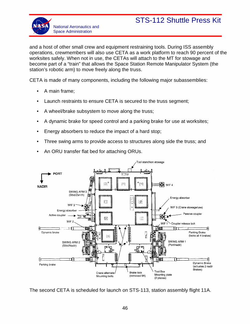
STS-112 Shuttle Press Kit National Aeronautics and Space Administration
and a host of other small crew and equipment restraining tools. During ISS assembly operations, crewmembers will also use CETA as a work platform to reach 90 percent of the worksites safely. When not in use, the CETAs will attach to the MT for stowage and become part of a “train” that allows the Space Station Remote Manipulator System (the station’s robotic arm) to move freely along the truss.
CETA is made of many components, including the following major subassemblies:
• A main frame;
• Launch restraints to ensure CETA is secured to the truss segment;
• A wheel/brake subsystem to move along the truss;
• A dynamic brake for speed control and a parking brake for use at worksites;
• Energy absorbers to reduce the impact of a hard stop;
• Three swing arms to provide access to structures along side the truss; and
• An ORU transfer flat bed for attaching ORUs.
The second CETA is scheduled for launch on STS-113, station assembly flight 11A.
46
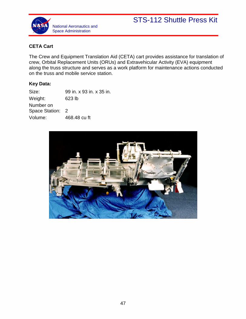
STS-112 Shuttle Press Kit National Aeronautics and Space Administration
CETA Cart
The Crew and Equipment Translation Aid (CETA) cart provides assistance for translation of crew, Orbital Replacement Units (ORUs) and Extravehicular Activity (EVA) equipment along the truss structure and serves as a work platform for maintenance actions conducted on the truss and mobile service station.
Key Data: Size: 99 in. x 93 in. x 35 in. Weight: 623 lb Number on Space Station: 2 Volume: 468.48 cu ft
47
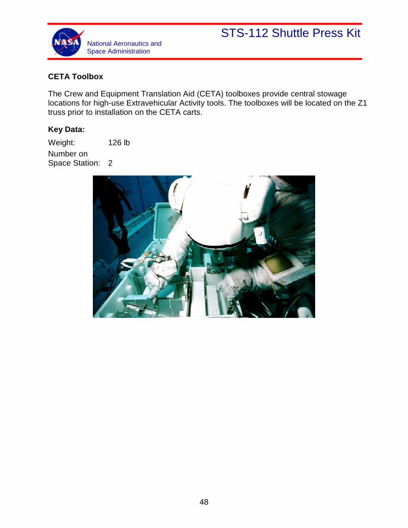
STS-112 Shuttle Press Kit National Aeronautics and Space Administration
CETA Toolbox
The Crew and Equipment Translation Aid (CETA) toolboxes provide central stowage locations for high-use Extravehicular Activity tools. The toolboxes will be located on the Z1 truss prior to installation on the CETA carts.
Key Data: Weight: 126 lb Number on Space Station: 2
48
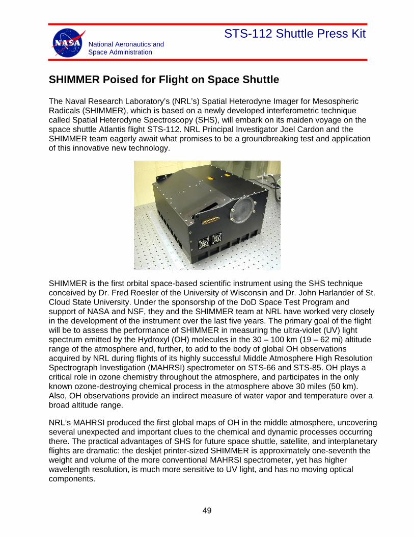
STS-112 Shuttle Press Kit National Aeronautics and Space Administration
SHIMMER Poised for Flight on Space Shuttle
The Naval Research Laboratory’s (NRL’s) Spatial Heterodyne Imager for Mesospheric Radicals (SHIMMER), which is based on a newly developed interferometric technique called Spatial Heterodyne Spectroscopy (SHS), will embark on its maiden voyage on the space shuttle Atlantis flight STS-112. NRL Principal Investigator Joel Cardon and the SHIMMER team eagerly await what promises to be a groundbreaking test and application of this innovative new technology.
SHIMMER is the first orbital space-based scientific instrument using the SHS technique conceived by Dr. Fred Roesler of the University of Wisconsin and Dr. John Harlander of St. Cloud State University. Under the sponsorship of the DoD Space Test Program and support of NASA and NSF, they and the SHIMMER team at NRL have worked very closely in the development of the instrument over the last five years. The primary goal of the flight will be to assess the performance of SHIMMER in measuring the ultra-violet (UV) light spectrum emitted by the Hydroxyl (OH) molecules in the 30 – 100 km (19 – 62 mi) altitude range of the atmosphere and, further, to add to the body of global OH observations acquired by NRL during flights of its highly successful Middle Atmosphere High Resolution Spectrograph Investigation (MAHRSI) spectrometer on STS-66 and STS-85. OH plays a critical role in ozone chemistry throughout the atmosphere, and participates in the only known ozone-destroying chemical process in the atmosphere above 30 miles (50 km). Also, OH observations provide an indirect measure of water vapor and temperature over a broad altitude range.
NRL’s MAHRSI produced the first global maps of OH in the middle atmosphere, uncovering several unexpected and important clues to the chemical and dynamic processes occurring there. The practical advantages of SHS for future space shuttle, satellite, and interplanetary flights are dramatic: the deskjet printer-sized SHIMMER is approximately one-seventh the weight and volume of the more conventional MAHRSI spectrometer, yet has higher wavelength resolution, is much more sensitive to UV light, and has no moving optical components.
49
STS-112 Shuttle Press Kit National Aeronautics and Space Administration
STS-112 Science Overview
Three new experiments and fresh supplies to continue research already under way on the Expedition 5 mission aboard the International Space Station will be launched on the STS-112 mission. Four completed experiments will be returned to Earth.
Expedition 5 began on June 5 when Space Shuttle Endeavour was launched to the Station with a new crew to replace the crew of Expedition 4. New laboratory equipment, as well as new experiments, will arrive onboard the International Space Station during Expedition 5.
Expedition 5 features a total of 24 new and continuing investigations – 10 human life sciences studies, six in microgravity, five in space product development, and three technology or education payloads.
NASA’s Marshall Space Flight Center in Huntsville, Ala., manages all science research experiment operations aboard the station, coordination of the science mission planning work of a variety of international sources, as well as payload training for the station crew and payload operations ground personnel.
Experiments headed for the space station on STS-112 are:
Commercial Generic Bioprocessing Apparatus (CGBA): CGBA will carry out investigations on the behavior of renal cortical cells and infectious agents, specifically yeast and salmonella, in the space environment on this shuttle flight. The experiment results will be used to help design improved bioreactor systems that optimize the ability to maintain long-term, large volume cultures on diverse cell types for pharmaceutical and medical applications. At the end of the flight, it will serve as a refrigerator to stabilize biological samples from the Plant Growth Bioprocessing Apparatus during their return to Earth for post-flight analyses.
Plant Growth Bioprocessing Apparatus (PGBA): An evolution of a space shuttle experiment, PGBA will investigate the effects of microgravity on plants. It will test the hypothesis that metabolic pathways are altered, resulting in differing ratios of materials normally devoted to structural integrity of the plant. The alteration of structural components is important to the paper, wood and food industries. This is the first flight for the PGBA experiment and the third CGBA flight.
Protein Crystal Growth Single-locker Thermal Enclosure System (PCG-STES): Following flights on Expeditions 2 and 4, this facility again provided a temperature-controlled environment for growing high-quality protein crystals of selected proteins in microgravity for analyses on the ground to determine the proteins’ molecular structure. Research may contribute to advances in medicine, agriculture and other fields.
50
STS-112 Shuttle Press Kit National Aeronautics and Space Administration
Zeolite Crystal Growth (ZCG): The shuttle will bring fresh zeolite samples for processing in the ZCG furnace, launched to the station in April 2002, and installed in EXPRESS Rack 2. ZCG is a commercial experiment attempting to grow zeolite crystals in microgravity, which will behave more efficiently in possible applications in chemical processes, petroleum manufacturing and other applications on Earth.
Experiments returning to Earth on STS-112 are:
Advanced Astroculture (ADVASC): A private agricultural seed company grew soybean plants in this experiment to determine if these space-grown plants produce seeds with a unique chemical composition. The major objective of the experiment was to determine whether soybean plants can produce seeds in a microgravity environment. Secondary objectives included determination of the chemical characteristics of the seeds produced in space and any microgravity impact on the plant growth cycle.
Protein Crystal Growth Single-locker Thermal Enclosure System (PCG-STES): The completed samples processed so far during Expedition 5 will be returned to Earth for analysis by scientists located around the world.
Microencapsulation Electrostatic Processing System (MEPS): Samples processed on board the station will be returned as part of this ongoing research. This commercial experiment is aimed at developing a process for producing large quantities of multi-layered microcapsules of drugs that could be placed in the human body. This process could provide new treatments for diseases such as cancer and drug resistant infection.
StelSys: Liver cell tissue samples cultured during Expedition 5 will be returned. One of the specialized functions of the liver is to break down drugs or toxins into less harmful and more water-soluble substances that can be excreted from the body. The StelSys experiment was designed to test this function of human liver cells in microgravity vs. the function of duplicate cells on Earth.
Zeolite Crystal Growth (ZCG): Crystals grown during Expedition 5 will be returned for analysis. ZCG is a commercial experiment attempting to grow zeolite crystals in microgravity, which will behave more efficiently in possible applications in chemical processes, petroleum manufacturing and other applications on Earth.
On the Internet:
For fact sheets, imagery and more on Expedition 5 experiments and payload operations, click on:
http://www.scipoc.msfc.nasa.gov
51
STS-112 Shuttle Press Kit National Aeronautics and Space Administration
Experiments
DSOs and DTOs
Detailed Supplementary Objectives (DSOs) are space and life science investigations. Their purpose is to:
• Determine the extent of physiological deconditioning resulting from spaceflight
• Test countermeasures to those changes and
• Characterize the environment of the space shuttle and/or space station relative to crew health.
Detailed Test Objectives (DTOs) are aimed at testing, evaluating or documenting space shuttle systems or hardware, or proposed improvements to the space shuttle or space station hardware, systems and operations.
Such experiments aboard during STS-112 are:
DSO 490-B
Bioavailability and Performance Effects of Promethazine During Space Flight
Promethazine (PMZ) is the anti-motion sickness medication of choice for treating Space Motion Sickness (SMS) during shuttle missions. The side effects associated with PMZ include dizziness, drowsiness, sedation, and impaired psychomotor performance, which could impact crew performance of mission operations. Early anecdotal reports from crewmembers indicate that these central nervous system side effects of PMZ are absent or greatly attenuated in microgravity.
The premise of this DSO is to evaluate the effects of microgravity on PMZ bioavailability, performance, side effects, and efficacy in the treatment of SMS; establish dose-response relationship of PMZ and the bioavailability of PMZ through intramuscular (IM), oral, and suppository routes of administration; and compare these results with preflight evaluations.
52
STS-112 Shuttle Press Kit National Aeronautics and Space Administration
DSO 493
Monitoring Latent Virus Reactivation and Shedding in Astronauts
The premise of this DSO is to determine the frequency of induced reactivation of herpes viruses, herpes virus shedding and clinical disease after exposure to the physical, physiological and psychological stressors associated with spaceflight.
DSO 498
Space Flight and Immune Function
The premise of this DSO is to characterize the effects of space flight on selected immune elements that are important in maintaining an effective defense against infectious agents. The roles of neutrophils, monocytes, and cytotoxic cells -- important elements of the immune response -- will be studied as part of this DSO.
DSO 499
Eye Movements and Motion Perception Induced by Off-Vertical Axis Rotation (OVAR) at Small Angles of Tilt After Spaceflight
The purpose of this study is to examine changes in spatial neural processing of gravitational tilt information following adaptation to microgravity. Postflight oculomotor and perceptual responses during off-vertical axis rotation will be compared with preflight baselines to track the time course of recovery. Comparison of data from short-duration and long-duration (ISS) crewmembers will assess the effect of flight duration.
DSO 501
Effects of Short-Duration Space Flight on Type 1/Type 2 Cytokine Balance and Its Endocrine Regulation (Pre and Post Flight Only)
Stress factors of space flight will affect the immune system in vivo and change the in vitro immune response to mitogens in the presence of stress hormones such as cortisol. It is thought that chronic stress-sensitization of immunocytes in vivo may result in:
1. A higher tolerance of immunocompetent cells to “stress” challenge in vitro, or
2. Exhausting the immune system and resulting in a deeper suppression of immunocyte functions in response to mitogen in cortisol-treated culture.
53
STS-112 Shuttle Press Kit National Aeronautics and Space Administration
The purpose of the proposed study is to investigate the effect of space flight on Type 1/Type 2-cytokine balance and a role of the neuro-endocrine system in it. The investigation is designed to answer questions such as:
• Does stress alter a distribution of Type 1 and/or Type 2 T-cells?
• Does stress affect a secretion of Type 1 and/or Type 2 cytokines in cell culture?
• Are any changes that occur neuro-endocrine induced or modulated?
DSO 503-S
Test of Midodrine as a Countermeasure Against Postflight Orthostatic Hypotension
Following exposure to spaceflight, upright posture can result in the inability to maintain adequate arterial pressure and cerebral perfusion (orthostatic or postural hypotension). This may result in presyncope (lightheadedness) or syncope (loss of consciousness) during re-entry or egress.
The purpose of this experiment is to evaluate a new pharmacological countermeasure for protection from postflight orthostatic hypotension. This experiment will measure the efficacy of midodrine in reducing the incidence and/or severity of orthostatic hypotension in returning astronauts. Efficacy will be evaluated with an expanded tilt test.
DSO 634
Sleep-Wake Actigraphy and Light Exposure During Spaceflight
Disruption of sleep during spaceflight, both short and long-duration, is associated with inappropriately timed (non-24 hour) or insufficiently intense light exposure. Sleep disruption and circadian misalignment will lead to subjective dissatisfaction with self-reported sleep quality and daytime alertness. Both of these conditions are associated with insomnia and associated impairment of alertness and cognitive performance that could impair mission success.
This experiment will use state-of-the-art ambulatory technology to monitor sleep-wake activity and light exposure patterns obtained in-flight. This data should help better understand the effects of space flight on sleep as well as aid in the development of effective countermeasures for both short and long-duration spaceflight.
54
STS-112 Shuttle Press Kit National Aeronautics and Space Administration
DSO 635
Spatial Reorientation Following Space Flight
Spatial orientation is altered during and after space flight by a shift of central vestibular processing (from a gravitational frame-of-reference to an internal, head-centered frame-of-reference) that occurs during adaptation to microgravity and is reversed during the first few days after return to Earth. Discordant sensory stimuli during the postflight re-adaptive period will temporarily disorient/ destabilize the subject by triggering a shift (state change) to the previously learned, internally referenced, microgravity-adapted pattern of spatial orientation and sensorimotor control.
The purpose of this DSO is to examine both the adaptive changes in the spatial reference frame used for coding spatial orientation and sensorimotor control as well as the fragility of the adaptive process and the feasibility of driving state changes in central vestibular processing via discordant sensory stimuli using balance control tests and eye movement responses to pitch-axis rotation in a short-arm centrifuge. The findings are expected to demonstrate the degree to which challenging motion environments may affect postflight adaptation or readaptation and lead to a better understanding of safe postflight activity regimens. The findings are also expected to demonstrate the feasibility of triggering state changes between sensorimotor control sets using a centrifuge device.
DTO 264
Space Station RMS Dynamic Model Validation
The purpose of DTO 264 is to assure stable Shuttle control system performance, and acceptable loads on the space shuttle remote manipulator system (SSRMS) induced by the shuttle jet firings.
During planned SSRMS handling of payloads, a brief pause is requested at a specific planned SSRMS geometric configuration in the operations preplanned trajectory. At this configuration, crew inputs to SSRMS motion will be commanded followed by an SSRMS brakes on command.
This will be performed three times to excite two lateral bending modes and one torsion mode of the SSRMS. The SSRMS data system in the end effector will be active to measure the SSRMS transient load response. Two flights are chosen to assess SSRMS dynamic characteristics while attached to a light space-limited payload and a heavy (airlock) payload.
55
STS-112 Shuttle Press Kit National Aeronautics and Space Administration
DTO 700-14
Single-String Global Positioning System
The purpose of the Single-String Global Positioning System (GPS) is to demonstrate the performance and operations of the GPS during orbiter ascent, on-orbit, entry and landing phases. It uses a modified military GPS receiver processor and the existing orbiter GPS antennas. This DTO has been previously manifested on 24 flights.
DTO 805
Crosswind Landing Performance
DTO 805 is to demonstrate the capability to perform a manually controlled landing in the presence of a 90-degree, 10-15 knots steady state crosswind. This DTO has been previously manifested on 72 flights.
56
STS-112 Shuttle Press Kit National Aeronautics and Space Administration
Experiments
Ram Burn Observations (RAMBO)
Ram Burn Observations (RAMBO) is a Department of Defense experiment that observes shuttle Orbital Maneuvering System engine burns for the purpose of improving plume models. On STS-112 the appropriate sensors will observe selected rendezvous and orbit adjust burns.
57
STS-112 Shuttle Press Kit National Aeronautics and Space Administration
Shuttle Reference Data
Shuttle Abort History
RSLS Abort History:
(STS-41 D) June 26, 1984
The countdown for the second launch attempt for Discovery’s maiden flight ended at T-4 seconds when the orbiter’s computers detected a sluggish valve in main engine #3.The main engine was replaced and Discovery was finally launched on August 30, 1984.
(STS-51 F) July 12, 1985
The countdown for Challenger’s launch was halted at T-3 seconds when on-boardcomputers detected a problem with a coolant valve on main engine #2. The valve wasreplaced and Challenger was launched on July 29, 1985.
(STS-55) March 22, 1993
The countdown for Columbia’s launch was halted by on-board computers at T-3seconds following a problem with purge pressure readings in the oxidizer preburner onmain engine #2 Columbia’s three main engines were replaced on the launch pad, andthe flight was rescheduled behind Discovery’s launch on STS-56. Columbia finallylaunched on April 26, 1993.
(STS-51) August 12, 1993
The countdown for Discovery’s third launch attempt ended at the T-3 second markwhen on-board computers detected the failure of one of four sensors in main engine #2which monitor the flow of hydrogen fuel to the engine. All of Discovery’s main engineswere ordered replaced on the launch pad, delaying the Shuttle’s fourth launch attemptuntil September 12, 1993.
(STS-68) August 18, 1994
The countdown for Endeavour’s first launch attempt ended 1.9 seconds before liftoffwhen on-board computers detected higher than acceptable readings in one channel of asensor monitoring the discharge temperature of the high pressure oxidizer turbopump inmain engine #3. A test firing of the engine at the Stennis Space Center in Mississippi onSeptember 2nd confirmed that a slight drift in a fuel flow meter in the engine caused aslight increase in the turbopump’s temperature. The test firing also confirmed a slightlyslower start for main engine #3 during the pad abort, which could have contributed tothe higher temperatures. After Endeavour was brought back to the Vehicle
58
STS-112 Shuttle Press Kit National Aeronautics and Space Administration
AssemblyBuilding to be outfitted with three replacement engines, NASA managers set October2nd as the date for Endeavour’s second launch attempt.
Abort to Orbit History:
(STS-51 F) July 29, 1985
After an RSLS abort on July 12, 1985, Challenger was launched on July 29, 1985. Fiveminutes and 45 seconds after launch, a sensor problem resulted in the shutdown ofcenter engine #1, resulting in a safe "abort to orbit" and successful completion of themission.
59
STS-112 Shuttle Press Kit National Aeronautics and Space Administration
Shuttle Reference Data
Shuttle Abort Modes
RSLS ABORTS
These occur when the onboard shuttle computers detect a problem and command a halt inthe launch sequence after taking over from the Ground Launch Sequencer and before SolidRocket Booster ignition.
ASCENT ABORTS
Selection of an ascent abort mode may become necessary if there is a failure that affectsvehicle performance, such as the failure of a space shuttle main engine or an orbitalmaneuvering system. Other failures requiring early termination of a flight, such as a cabinleak, might also require the selection of an abort mode. There are two basic types of ascent abort modes for space shuttle missions: intact aborts
and contingency aborts. Intact aborts are designed to provide a safe return of the orbiter toa planned landing site. Contingency aborts are designed to permit flight crew survivalfollowing more severe failures when an intact abort is not possible. A contingency abort would generally result in a ditch operation.
INTACT ABORTS
There are four types of intact aborts: abort to orbit (ATO), abort once around (AOA), transoceanic abort landing (TAL) and return to launch site (RTLS).
Return to Launch Site
The RTLS abort mode is designed to allow the return of the orbiter, crew, and payload tothe launch site, Kennedy Space Center, approximately 25 minutes after lift-off.The RTLS profile is designed to accommodate the loss of thrust from one space shuttle main engine between lift-off and approximately four minutes 20 seconds, at which time not enough main propulsion system propellant remains to return to the launch site. An RTLS can be considered to consist of three stages--a powered stage, during which the space shuttle main engines are still thrusting; an ET separation phase; and the glide phase, during which the orbiter glides to a landing at the Kennedy Space Center. The powered RTLS phase begins with the crew selection of the RTLS abort, which is done after solid rocket booster separation. The crew selects the abort mode by positioning the abort rotary switch to RTLS and depressing the abort push button. The time at which the RTLS is selected depends on the reason for the abort. For example, a three-engine RTLS is selected at the last moment, approximately three minutes 34 seconds into the mission; whereas an RTLS chosen due to
60
STS-112 Shuttle Press Kit National Aeronautics and Space Administration
an engine out at lift-off is selected at the earliest time, approximately two minutes 20 seconds into the mission (after solid rocket booster separation).
After RTLS is selected, the vehicle continues downrange to dissipate excess main propulsion system propellant. The goal is to leave only enough main propulsion system propellant to be able to turn the vehicle around, fly back towards the Kennedy Space Center and achieve the proper main engine cutoff conditions so the vehicle can glide to the Kennedy Space Center after external tank separation. During the downrange phase, a pitch-around maneuver is initiated (the time depends in part on the time of a space shuttle main engine failure) to orient the orbiter/external tank configuration to a heads up attitude, pointing toward the launch site. At this time, the vehicle is still moving away from the launch site, but the space shuttle main engines are now thrusting to null the downrange velocity. In addition, excess orbital maneuvering system and reaction control system propellants are dumped by continuous orbital maneuvering system and reaction control system engine thrustings to improve the orbiter weight and center of gravity for the glide phase and landing.
The vehicle will reach the desired main engine cutoff point with less than 2 percent excess propellant remaining in the external tank. At main engine cutoff minus 20 seconds, a pitchdown maneuver (called powered pitch-down) takes the mated vehicle to the required external tank separation attitude and pitch rate. After main engine cutoff has been commanded, the external tank separation sequence begins, including a reaction control system translation that ensures that the orbiter does not recontact the external tank and that the orbiter has achieved the necessary pitch attitude to begin the glide phase of the RTLS.
After the reaction control system translation maneuver has been completed, the glide phase of the RTLS begins. From then on, the RTLS is handled similarly to a normal entry.
Transoceanic Abort Landing
The TAL abort mode was developed to improve the options available when a space shuttle main engine fails after the last RTLS opportunity but before the first time that an AOA can be accomplished with only two space shuttle main engines or when a major orbiter system failure, for example, a large cabin pressure leak or cooling system failure, occurs after the last RTLS opportunity, making it imperative to land as quickly as possible.
In a TAL abort, the vehicle continues on a ballistic trajectory across the Atlantic Ocean to land at a predetermined runway. Landing occurs approximately 45 minutes after launch. The landing site is selected near the nominal ascent ground track of the orbiter in order to make the most efficient use of space shuttle main engine propellant. The landing site also must have the necessary runway length, weather conditions and U.S. State Department approval. Currently, the three landing sites that have been identified for a due east launch are Moron, Spain; Dakar, Senegal; and Ben Guerur, Morocco (on the west coast of Africa).
61
STS-112 Shuttle Press Kit National Aeronautics and Space Administration
To select the TAL abort mode, the crew must place the abort rotary switch in the TAL/AOA position and depress the abort push button before main engine cutoff. (Depressing it after main engine cutoff selects the AOA abort mode.) The TAL abort mode begins sending commands to steer the vehicle toward the plane of the landing site. It also rolls the vehicle heads up before main engine cutoff and sends commands to begin an orbital maneuvering system propellant dump (by burning the propellants through the orbital maneuveringsystem engines and the reaction control system engines). This dump is necessary to increase vehicle performance (by decreasing weight), to place the center of gravity in the proper place for vehicle control, and to decrease the vehicle's landing weight.
TAL is handled like a nominal entry.
Abort to Orbit
An ATO is an abort mode used to boost the orbiter to a safe orbital altitude when performance has been lost and it is impossible to reach the planned orbital altitude. If a space shuttle main engine fails in a region that results in a main engine cutoff under speed, the Mission Control Center will determine that an abort mode is necessary and will inform the crew. The orbital maneuvering system engines would be used to place the orbiter in a circular orbit.
Abort Once Around
The AOA abort mode is used in cases in which vehicle performance has been lost to such an extent that either it is impossible to achieve a viable orbit or not enough orbital maneuvering system propellant is available to accomplish the orbital maneuvering system thrusting maneuver to place the orbiter on orbit and the deorbit thrusting maneuver. In addition, an AOA is used in cases in which a major systems problem (cabin leak, loss of cooling) makes it necessary to land quickly. In the AOA abort mode, one orbital maneuvering system thrusting sequence is made to adjust the post-main engine cutoff orbit so a second orbital maneuvering system thrusting sequence will result in the vehicle deorbiting and landing at the AOA landing site (White Sands, N.M.; Edwards Air Force Base; or the Kennedy Space Center). Thus, an AOA results in the orbiter circling the Earth once and landing approximately 90 minutes after lift-off.
After the deorbit thrusting sequence has been executed, the flight crew flies to a landing at the planned site much as it would for a nominal entry.
CONTINGENCY ABORTS Contingency aborts are caused by loss of more than one main engine or failures in other systems. Loss of one main engine while another is stuck at a low thrust setting may also necessitate a contingency abort. Such an abort would maintain orbiter integrity for in-flight crew escape if a landing cannot be achieved at a suitable landing field.
62
STS-112 Shuttle Press Kit National Aeronautics and Space Administration
Contingency aborts due to system failures other than those involving the main engines would normally result in an intact recovery of vehicle and crew. Loss of more than one main engine may, depending on engine failure times, result in a safe runway landing. However, in most three-engine-out cases during ascent, the orbiter would have to be ditched. The inflight crew escape system would be used before ditching the orbiter.
ABORT DECISIONS
There is a definite order of preference for the various abort modes. The type of failure and the time of the failure determine which type of abort is selected. In cases where performance loss is the only factor, the preferred modes would be ATO, AOA, TAL and RTLS, in that order. The mode chosen is the highest one that can be completed with the remaining vehicle performance.
In the case of some support system failures, such as cabin leaks or vehicle cooling problems, the preferred mode might be the one that will end the mission most quickly. In these cases, TAL or RTLS might be preferable to AOA or ATO. A contingency abort is never chosen if another abort option exists.
The Mission Control Center-Houston is prime for calling these aborts because it has a more precise knowledge of the orbiter's position than the crew can obtain from onboard systems. Before main engine cutoff, Mission Control makes periodic calls to the crew to tell them which abort mode is (or is not) available. If ground communications are lost, the flight crew has onboard methods, such as cue cards, dedicated displays and display information, to determine the current abort region.
Which abort mode is selected depends on the cause and timing of the failure causing the abort and which mode is safest or improves mission success. If the problem is a space shuttle main engine failure, the flight crew and Mission Control Center select the best option available at the time a space shuttle main engine fails.
If the problem is a system failure that jeopardizes the vehicle, the fastest abort mode that results in the earliest vehicle landing is chosen. RTLS and TAL are the quickest options (35 minutes), whereas an AOA requires approximately 90 minutes. Which of these is selected depends on the time of the failure with three good space shuttle main engines.
The flight crew selects the abort mode by positioning an abort mode switch and depressing an abort push button.
63
STS-112 Shuttle Press Kit National Aeronautics and Space Administration
Shuttle Reference Data
Space Shuttle Rendezvous Maneuvers
COMMON SHUTTLE RENDEZVOUS MANEUVERS
OMS-1 (Orbit insertion) - Rarely used ascent abort burn
OMS-2 (Orbit insertion) - Typically used to circularize the initial orbit following ascent, completing orbital insertion. For ground-up rendezvous flights, also considered a rendezvous phasing burn
NC (Rendezvous phasing) - Performed to hit a range relative to the target at a future time
NH (Rendezvous height adjust) - Performed to hit a delta-height relative to the target at a future time
NPC (Rendezvous plane change) - Performed to remove planar errors relative to the target at a future time
NCC (Rendezvous corrective combination) - First on-board targeted burn in the rendezvous sequence. Using star tracker data, it is performed to remove phasing and height errors relative to the target at Ti
Ti (Rendezvous terminal intercept) - Second on-board targeted burn in the rendezvous sequence. Using primarily rendezvous radar data, it places the Orbiter on a trajectory to intercept the target in one orbit
MC-1, MC-2, MC-3, MC-4 (Rendezvous midcourse burns) - These on-board targeted burns use star tracker and rendezvous radar data to correct the post-Ti trajectory in preparation for the final, manual proximity operations phase
64
STS-112 Shuttle Press Kit National Aeronautics and Space Administration
Shuttle Reference Data
Space Shuttle Main Engines
Developed in the 1970s by NASA's Marshall Space Flight Center in Huntsville, Ala., the Space Shuttle Main Engine is the most advanced liquid-fueled rocket engine ever built. Its main features include variable thrust, high performance, reusability, high redundancy, and a fully integrated engine controller.
The shuttle’s three main engines are mounted on the Orbiter aft fuselage in a triangular pattern. Spaced so that they are movable during launch, the engines are used – in conjunction with the Solid Rocket Boosters – to steer the shuttle vehicle.
Each of these powerful main engines is 14 feet (4.2 meters) long, weighs approximately 7,000 pounds (3,150 kilograms) and is 7.5 feet (2.25 meters) in diameter at the end of its nozzle.
The engines operate for about eight-and-one-half minutes during liftoff and ascent -- burning more than 500,000 gallons (1.9 million liters) of super-cold liquid hydrogen and liquid oxygen propellants stored in the huge external tank attached to the underside of the shuttle. The engines shut down just before the shuttle, traveling at about 17,000 mph (28,000 kilometers per hour), reaches orbit.
The Main Engine operates at greater temperature extremes than any mechanical system in common use today. The fuel, liquefied hydrogen at -423 degrees Fahrenheit (-253 degrees Celsius) is the second coldest liquid on Earth. When it and the liquid oxygen are combusted, the temperature in the main combustion chamber is 6,000 degrees Fahrenheit (3,316 degrees Celsius), hotter than the boiling point of iron.
The main engines use a staged combustion cycle so that all propellants entering the engines are used to produce thrust or power -- more efficiently than any previous rocket engine. In a staged combustion cycle, propellants are first burned partially at high pressure and relatively low temperature -- then burned completely at high temperature and pressure in the main combustion chamber. The rapid mixing of the propellants under these conditions is so complete that 99 percent of the fuel is burned.
At normal operating level, the engines generate 490,847 pounds of thrust (measured in a vacuum). Full power is 512,900 pounds of thrust; minimum power is at 316,100 pounds of thrust.
The engine can be throttled by varying the output of the pre-burners, thus varying the speed of the high-pressure turbopumps and, therefore, the flow of the propellant.
65
STS-112 Shuttle Press Kit National Aeronautics and Space Administration
At approximately 26 seconds into launch the main engines are throttled down to 316,000 pounds of thrust to keep the dynamic pressure on the vehicle below a specified level -- about 580 pounds per square foot or max q. Then, the engines are throttled back up to normal operating level at approximately 60 seconds. This reduces stress on the vehicle.
The main engines are throttled down again at approximately seven minutes 40 seconds into the mission to maintain 3 g’s – three times the Earth’s gravitational pull – again reducing stress on the crew and the vehicle. This acceleration level is about one-third the acceleration experienced on previous crewed space flights.
Approximately 10 seconds before Main Engine Cutoff or MECO, the cutoff sequence begins; about three seconds later the main engines are commanded to begin throttling at 10-percent thrust per second to 65-percent thrust. This is held for approximately 6.7seconds, and the engines are shut down.
The engine performance has the highest thrust for its weight of any engine yet developed. In fact, one Space Shuttle Main Engine generates sufficient thrust to maintain the flight of two-and-one-half 747 airplanes.
The Space Shuttle Main Engine is also the first rocket engine to use a built-in electronic digital controller, or computer. The controller will accept commands from the Orbiter for engine start, change in throttle, shutdown, and monitor engine operation. In the event of a failure, the controller automatically corrects the problem or safely shuts down the engine.
NASA continues to increase the reliability and safety of shuttle flights through a series of enhancements to the Space Shuttle Main Engines. The engines were modified in 1988, 1995, 1998 and 2001. Modifications include new high-pressure fuel and oxidizer turbopumps that reduce maintenance and operating costs of the engine, a two-duct powerhead that reduces pressure and turbulence in the engine, a single-coil heat exchanger that lowers the number of post flight inspections required. Another modification incorporates a large-throat main combustion chamber that improves the engine’s reliability by reducing pressure and temperature in the chamber.
NASA projects an upcoming enhancement – the Advanced Health Management System – will further improve safety, reliability and performance. The Advanced Health Management System is a high tech system that couples optical and vibration sensors with advanced processing and computing technology. It will monitor the main engines and “see” any problems. After the orbiter lands, the engines are removed and returned to a processing facility at Kennedy Space Center, Fla., where they are rechecked and readied for the next flight. Some components are returned to the main engine’s prime contractor, Rocketdyne Propulsion & Power unit of the Boeing Company, Canoga Park, Calif., for regular maintenance. The main engines are designed to operate for 7.5 accumulated hours.
66
STS-112 Shuttle Press Kit National Aeronautics and Space Administration
Shuttle Reference Data
Space Shuttle Solid Rocket Boosters
The two SRBs provide the main thrust to lift the space shuttle off the pad and up to an altitude of about 150,000 feet, or 24 nautical miles (28 statute miles). In addition, the two SRBs carry the entire weight of the external tank and orbiter and transmit the weight load through their structure to the mobile launcher platform.
Each booster has a thrust (sea level) of approximately 3,300,000 pounds at launch. They are ignited after the three space shuttle main engines' thrust level is verified. The two SRBs provide 71.4 percent of the thrust at lift- off and during first-stage ascent. Seventy- five seconds after SRB separation, SRB apogee occurs at an altitude of approximately 220,000 feet, or 35 nautical miles (40 statute miles). SRB impact occurs in the ocean approximately 122 nautical miles (140 statute miles) downrange.
The SRBs are the largest solid-propellant motors ever flown and the first designed for reuse. Each is 149.16 feet long and 12.17 feet in diameter.
Each SRB weighs approximately 1,300,000 pounds at launch. The propellant for each solid rocket motor weighs approximately 1,100,000 pounds. The inert weight of each SRB is approximately 192,000 pounds.
Primary elements of each booster are the motor (including case, propellant, igniter and nozzle), structure, separation systems, operational flight instrumentation, recovery avionics, pyrotechnics, deceleration system, thrust vector control system and range safety destruct system.
Each booster is attached to the external tank at the SRB’s aft frame by two lateral sway braces and a diagonal attachment. The forward end of each SRB is attached to the external tank at the forward end of the SRB’s forward skirt. On the launch pad, each booster also is attached to the mobile launcher platform at the aft skirt by four bolts and nuts that are severed by small explosives at lift-off.
During the downtime following the Challenger accident, detailed structural analyses were performed on critical structural elements of the SRB. Analyses were primarily focused in areas where anomalies had been noted during postflight inspection of recovered hardware.
One of the areas was the attach ring where the SRBs are connected to the external tank. Areas of distress were noted in some of the fasteners where the ring attaches to the SRB motor case. This situation was attributed to the high loads encountered during water impact. To correct the situation and ensure higher strength margins during ascent, the attach ring was redesigned to encircle the motor case completely (360 degrees). Previously, the attach ring formed a C and encircled the motor case 270 degrees.
67
STS-112 Shuttle Press Kit National Aeronautics and Space Administration
Additionally, special structural tests were performed on the aft skirt. During this test program, an anomaly occurred in a critical weld between the hold-down post and skin of the skirt. A redesign was implemented to add reinforcement brackets and fittings in the aft ring of the skirt.
These two modifications added approximately 450 pounds to the weight of each SRB.
The propellant mixture in each SRB motor consists of an ammonium perchlorate (oxidizer, 69.6 percent by weight), aluminum (fuel, 16 percent), iron oxide (a catalyst, 0.4 percent), a polymer (a binder that holds the mixture together, 12.04 percent), and an epoxy curing agent (1.96 percent). The propellant is an 11-point star-shaped perforation in the forward motor segment and a double-truncated-cone perforation in each of the aft segments and aft closure. This configuration provides high thrust at ignition and then reduces the thrust by approximately a third 50 seconds after lift-off to prevent overstressing the vehicle during maximum dynamic pressure.
The SRBs are used as matched pairs and each is made up of four solid rocket motor segments. The pairs are matched by loading each of the four motor segments in pairs from the same batches of propellant ingredients to minimize any thrust imbalance. The segmented-casing design assures maximum flexibility in fabrication and ease of transportation and handling. Each segment is shipped to the launch site on a heavy-duty rail car with a specially built cover.
The nozzle expansion ratio of each booster beginning with the STS-8 mission is 7-to-79. The nozzle is gimbaled for thrust vector (direction) control. Each SRB has its own redundant auxiliary power units and hydraulic pumps. The all-axis gimbaling capability is 8 degrees. Each nozzle has a carbon cloth liner that erodes and chars during firing. The nozzle is a convergent-divergent, movable design in which an aft pivot-point flexible bearing is the gimbal mechanism.
The cone- shaped aft skirt reacts the aft loads between the SRB and the mobile launcher platform. The four aft separation motors are mounted on the skirt. The aft section contains avionics, a thrust vector control system that consists of two auxiliary power units and hydraulic pumps, hydraulic systems and a nozzle extension jettison system.
The forward section of each booster contains avionics, a sequencer, forward separation motors, a nose cone separation system, drogue and main parachutes, a recovery beacon, a recovery light, a parachute camera on selected flights and a range safety system.
Each SRB has two integrated electronic assemblies, one forward and one aft. After burnout, the forward assembly initiates the release of the nose cap and frustum and turns on the recovery aids. The aft assembly, mounted in the external tank/SRB attach ring, connects with the forward assembly and the orbiter avionics systems for SRB ignition commands and nozzle thrust vector control. Each integrated electronic assembly has a
68
STS-112 Shuttle Press Kit National Aeronautics and Space Administration
multiplexer/ demultiplexer, which sends or receives more than one message, signal or unit of information on a single communication channel.
Eight booster separation motors (four in the nose frustum and four in the aft skirt) of each SRB thrust for 1.02 seconds at SRB separation from the external tank. Each solid rocket separation motor is 31.1 inches long and 12.8 inches in diameter.
Location aids are provided for each SRB, frustum/drogue chutes and main parachutes. These include a transmitter, antenna, strobe/converter, battery and salt water switchelectronics. The location aids are designed for a minimum operating life of 72 hours and when refurbished are considered usable up to 20 times. The flashing light is an exception. It has an operating life of 280 hours. The battery is used only once.
The SRB nose caps and nozzle extensions are not recovered.
The recovery crew retrieves the SRBs, frustum/drogue chutes, and main parachutes. The nozzles are plugged, the solid rocket motors are dewatered, and the SRBs are towed back to the launch site. Each booster is removed from the water, and its components are disassembled and washed with fresh and deionized water to limit salt water corrosion. The motor segments, igniter and nozzle are shipped back to Thiokol for refurbishment.
Each SRB incorporates a range safety system that includes a battery power source, receiver/ decoder, antennas and ordnance.
HOLD-DOWN POSTS
Each solid rocket booster has four hold-down posts that fit into corresponding support posts on the mobile launcher platform. Hold-down bolts hold the SRB and launcher platform posts together. Each bolt has a nut at each end, but only the top nut is frangible. The top nut contains two NASA standard detonators, which are ignited at solid rocket motor ignition commands.
When the two NSDs are ignited at each hold-down, the hold-down bolt travels downward because of the release of tension in the bolt (pretensioned before launch), NSD gas pressure and gravity. The bolt is stopped by the stud deceleration stand, which contains sand. The SRB bolt is 28 inches long and is 3.5 inches in diameter. The frangible nut is captured in a blast container.
The solid rocket motor ignition commands are issued by the orbiter''s computers through the master events controllers to the hold-down pyrotechnic initiator controllers on the mobile launcher platform. They provide the ignition to the hold-down NSDs. The launch processing system monitors the SRB hold-down PICs for low voltage during the last 16 seconds before launch. PIC low voltage will initiate a launch hold.
69
STS-112 Shuttle Press Kit National Aeronautics and Space Administration
SRB IGNITION
SRB ignition can occur only when a manual lock pin from each SRB safe and arm device has been removed. The ground crew removes the pin during prelaunch activities. At T minus five minutes, the SRB safe and arm device is rotated to the arm position. The solid rocket motor ignition commands are issued when the three SSMEs are at or above 90- percent rated thrust, no SSME fail and/or SRB ignition PIC low voltage is indicated and there are no holds from the LPS.
The solid rocket motor ignition commands are sent by the orbiter computers through the MECs to the safe and arm device NSDs in each SRB. A PIC single-channel capacitor discharge device controls the firing of each pyrotechnic device. Three signals must be present simultaneously for the PIC to generate the pyro firing output. These signals--arm, fire 1 and fire 2--originate in the orbiter general-purpose computers and are transmitted to the MECs. The MECs reformat them to 28-volt dc signals for the PICs. The arm signal charges the PIC capacitor to 40 volts dc (minimum of 20 volts dc).
The fire 2 commands cause the redundant NSDs to fire through a thin barrier seal down a flame tunnel. This ignites a pyro booster charge, which is retained in the safe and arm device behind a perforated plate. The booster charge ignites the propellant in the igniter initiator; and combustion products of this propellant ignite the solid rocket motor initiator, which fires down the length of the solid rocket motor igniting the solid rocket motor propellant.
The GPC launch sequence also controls certain critical main propulsion system valves and monitors the engine-ready indications from the SSMEs. The MPS start commands are issued by the onboard computers at T minus 6.6 seconds (staggered start--engine three, engine two, engine one--all approximately within 0.25 of a second), and the sequence monitors the thrust buildup of each engine. All three SSMEs must reach the required 90- percent thrust within three seconds; otherwise, an orderly shutdown is commanded and safing functions are initiated.
Normal thrust buildup to the required 90-percent thrust level will result in the SSMEs being commanded to the lift-off position at T minus three seconds as well as the fire 1 command being issued to arm the SRBs. At T minus three seconds, the vehicle base bending load modes are allowed to initialize (movement of approximately 25.5 inches measured at the tip of the external tank, with movement towards the external tank).
At T minus zero, the two SRBs are ignited, under command of the four onboard computers; separation of the four explosive bolts on each SRB is initiated (each bolt is 28 inches long and 3.5 inches in diameter); the two T-0 umbilicals (one on each side of the spacecraft) are retracted; the onboard master timing unit, event timer and mission event timers are started; the three SSMEs are at 100 percent; and the ground launch sequence is terminated.
70
STS-112 Shuttle Press Kit National Aeronautics and Space Administration
The solid rocket motor thrust profile is tailored to reduce thrust during the maximum dynamic pressure region.
ELECTRICAL POWER DISTRIBUTION
Electrical power distribution in each SRB consists of orbiter-supplied main dc bus power to each SRB via SRB buses A, B and C. Orbiter main dc buses A, B and C supply main dc bus power to corresponding SRB buses A, B and C. In addition, orbiter main dc bus C supplies backup power to SRB buses A and B, and orbiter bus B supplies backup power to SRB bus C. This electrical power distribution arrangement allows all SRB buses to remain powered in the event one orbiter main bus fails.
The nominal dc voltage is 28 volts dc, with an upper limit of 32 volts dc and a lower limit of 24 volts dc.
HYDRAULIC POWER UNITS
There are two self-contained, independent HPUs on each SRB. Each HPU consists of an auxiliary power unit, fuel supply module, hydraulic pump, hydraulic reservoir and hydraulic fluid manifold assembly. The APUs are fueled by hydrazine and generate mechanical shaft power to a hydraulic pump that produces hydraulic pressure for the SRB hydraulic system. The two separate HPUs and two hydraulic systems are located on the aft end of each SRB between the SRB nozzle and aft skirt. The HPU components are mounted on the aft skirt between the rock and tilt actuators. The two systems operate from T minus 28 seconds until SRB separation from the orbiter and external tank. The two independent hydraulic systems are connected to the rock and tilt servoactuators.
The APU controller electronics are located in the SRB aft integrated electronic assemblies on the aft external tank attach rings.
The APUs and their fuel systems are isolated from each other. Each fuel supply module (tank) contains 22 pounds of hydrazine. The fuel tank is pressurized with gaseous nitrogen at 400 psi, which provides the force to expel (positive expulsion) the fuel from the tank to the fuel distribution line, maintaining a positive fuel supply to the APU throughout its operation.
The fuel isolation valve is opened at APU startup to allow fuel to flow to the APU fuel pump and control valves and then to the gas generator. The gas generator's catalytic action decomposes the fuel and creates a hot gas. It feeds the hot gas exhaust product to the APU two-stage gas turbine. Fuel flows primarily through the startup bypass line until the APU speed is such that the fuel pump outlet pressure is greater than the bypass line's. Then all the fuel is supplied to the fuel pump.
The APU turbine assembly provides mechanical power to the APU gearbox. The gearbox drives the APU fuel pump, hydraulic pump and lube oil pump. The APU lube oil pump
71
STS-112 Shuttle Press Kit National Aeronautics and Space Administration
lubricates the gearbox. The turbine exhaust of each APU flows over the exterior of the gas generator, cooling it, and is then directed overboard through an exhaust duct.
When the APU speed reaches 100 percent, the APU primary control valve closes, and the APU speed is controlled by the APU controller electronics. If the primary control valve logic fails to the open state, the secondary control valve assumes control of the APU at 112-percent speed.
Each HPU on an SRB is connected to both servoactuators on that SRB. One HPU serves as the primary hydraulic source for the servoactuator, and the other HPU serves as the secondary hydraulics for the servoactuator. Each sevoactuator has a switching valve that allows the secondary hydraulics to power the actuator if the primary hydraulic pressure drops below 2,050 psi. A switch contact on the switching valve will close when the valve is in the secondary position. When the valve is closed, a signal is sent to the APU controller that inhibits the 100-percent APU speed control logic and enables the 112-percent APU speed control logic. The 100-percent APU speed enables one APU/HPU to supply sufficient operating hydraulic pressure to both servoactuators of that SRB.
The APU 100-percent speed corresponds to 72,000 rpm, 110-percent to 79,200 rpm, and 112-percent to 80,640 rpm.
The hydraulic pump speed is 3,600 rpm and supplies hydraulic pressure of 3,050, plus or minus 50, psi. A high-pressure relief valve provides overpressure protection to the hydraulic system and relieves at 3,750 psi.
The APUs/HPUs and hydraulic systems are reusable for 20 missions.
THRUST VECTOR CONTROL
Each SRB has two hydraulic gimbal servoactuators: one for rock and one for tilt. The servoactuators provide the force and control to gimbal the nozzle for thrust vector control.
The space shuttle ascent thrust vector control portion of the flight control system directs the thrust of the three shuttle main engines and the two SRB nozzles to control shuttle attitude and trajectory during lift-off and ascent. Commands from the guidance system are transmitted to the ATVC drivers, which transmit signals proportional to the commands to each servoactuator of the main engines and SRBs. Four independent flight control system channels and four ATVC channels control six main engine and four SRB ATVC drivers, with each driver controlling one hydraulic port on each main and SRB servoactuator.
Each SRB servoactuator consists of four independent, two-stage servovalves that receive signals from the drivers. Each servovalve controls one power spool in each actuator, which positions an actuator ram and the nozzle to control the direction of thrust.
72
STS-112 Shuttle Press Kit National Aeronautics and Space Administration
The four servovalves in each actuator provide a force-summed majority voting arrangement to position the power spool. With four identical commands to the four servovalves, the actuator force-sum action prevents a single erroneous command from affecting power ram motion. If the erroneous command persists for more than a predetermined time, differential pressure sensing activates a selector valve to isolate and remove the defective servovalve hydraulic pressure, permitting the remaining channels and servovalves to control the actuator ram spool.
Failure monitors are provided for each channel to indicate which channel has been bypassed. An isolation valve on each channel provides the capability of resetting a failed or bypassed channel.
Each actuator ram is equipped with transducers for position feedback to the thrust vector control system. Within each servoactuator ram is a splashdown load relief assembly to cushion the nozzle at water splashdown and prevent damage to the nozzle flexible bearing.
SRB RATE GYRO ASSEMBLIES
Each SRB contains two RGAs, with each RGA containing one pitch and one yaw gyro. These provide an output proportional to angular rates about the pitch and yaw axes to the orbiter computers and guidance, navigation and control system during first-stage ascent flight in conjunction with the orbiter roll rate gyros until SRB separation. At SRB separation, a switchover is made from the SRB RGAs to the orbiter RGAs.
The SRB RGA rates pass through the orbiter flight aft multiplexers/ demultiplexers to the orbiter GPCs. The RGA rates are then mid-value- selected in redundancy management to provide SRB pitch and yaw rates to the user software. The RGAs are designed for 20 missions.
SRB SEPARATION
SRB separation is initiated when the three solid rocket motor chamber pressure transducers are processed in the redundancy management middle value select and the head-end chamber pressure of both SRBs is less than or equal to 50 psi. A backup cue is the time elapsed from booster ignition.
The separation sequence is initiated, commanding the thrust vector control actuators to the null position and putting the main propulsion system into a second-stage configuration (0.8 second from sequence initialization), which ensures the thrust of each SRB is less than 100,000 pounds. Orbiter yaw attitude is held for four seconds, and SRB thrust drops to less than 60,000 pounds.
The SRBs separate from the external tank within 30 milliseconds of the ordnance firing command.
73
STS-112 Shuttle Press Kit National Aeronautics and Space Administration
The forward attachment point consists of a ball (SRB) and socket (ET) held together by one bolt. The bolt contains one NSD pressure cartridge at each end. The forward attachment point also carries the range safety system cross-strap wiring connecting each SRB RSS and the ET RSS with each other.
The aft attachment points consist of three separate struts: upper, diagonal and lower. Each strut contains one bolt with an NSD pressure cartridge at each end. The upper strut also carries the umbilical interface between its SRB and the external tank and on to the orbiter.
There are four booster separation motors on each end of each SRB. The BSMs separate the SRBs from the external tank. The solid rocket motors in each cluster of four are ignited by firing redundant NSD pressure cartridges into redundant confined detonating fuse manifolds.
The separation commands issued from the orbiter by the SRB separation sequence initiate the redundant NSD pressure cartridge in each bolt and ignite the BSMs to effect a clean separation.
74
STS-112 Shuttle Press Kit National Aeronautics and Space Administration
Shuttle Reference Data
Space Shuttle Super Light Weight Tank (SLWT)
The super lightweight external tank (SLWT) made its first shuttle flight June 2, 1998, on mission STS-91. The SLWT is 7,500 pounds lighter than the standard external tank. The lighter weight tank will allow the shuttle to deliver International Space Station elements (such as the service module) into the proper orbit.
The SLWT is the same size as the previous design. But the liquid hydrogen tank and the liquid oxygen tank are made of aluminum lithium, a lighter, stronger material than the metal alloy used for the shuttle's current tank. The tank's structural design has also been improved, making it 30% stronger and 5% less dense.
The SLWT, like the standard tank, is manufactured at Michoud Assembly, near New Orleans, Louisiana, by Lockheed Martin.
The 154-foot-long external tank is the largest single component of the space shuttle. It stands taller than a 15-story building and has a diameter of about 27 feet. The external tank holds over 530,000 gallons of liquid hydrogen and liquid oxygen in two separate tanks. The hydrogen (fuel) and liquid oxygen (oxidizer) are used as propellants for the shuttle's three main engines.
75
STS-112 Shuttle Press Kit National Aeronautics and Space Administration
Acronyms and Abbreviations
A/L Airlock AA Antenna Assembly AAA Avionics Air Assembly ABC Audio Bus Coupler AC Assembly Complete ACBM Active CBM ACS Assembly Contingency System Atmosphere Control and Supply Attitude Control System ACU Arm Computer Unit ADVASC-GC Advanced Astroculture – Growth Chamber AEA Antenna Electronics Assembly AOH Assembly Operations Handbook APAS Androgynous Peripheral Attachment System APCU Assembly Power Converter Unit APDS Androgynous Peripheral Docking System APFR Articulating Portable Foot Restraint APM Attached Pressurized Module APPCM Arm Pitch Plane Change Mode APS Automated Payload Switch AR Atmosphere Revitalization ARCU American-to-Russian Converter Unit ARIS Active Rack Isolation System ARS Air Revitalization System Atmosphere Revitalization System ASCR Assured Safe Crew Return ATA Ammonia Tank Assembly ATCS Active Thermal Control System ATU Audio Terminal Unit AUAI Assembly Contingency System/UHF Audio Interface AVV Accumulator Vent Valve
BBC Bus Bolt Controller BC Bus Controller BCDU Battery Charge/Discharge Unit BCU Backup Control Unit Bus Controller Unit BDU Backup Drive Unit BG Beta Gimbal BGA Beta Gimbal Assembly BGDTS Beta Gimbal Deployment Transition Structure
76

STS-112 Shuttle Press Kit National Aeronautics and Space Administration
BGHS Beta Gimbal Housing Subassembly BIT Built-In Test BITE Built-In Test Equipment BMRRM Bearing Motor and Roll Ring Module BSP Baseband Signal Processor
C&C Command and Control C&DH Command and Data Handling C&M Control and Monitor C&T Communication and Tracking C&W Caution and Warning C/A-code Coarse/Acquisition-code C/L Crew Lock CA Control Attitude CAS Common Attach System CBM Common Berthing Mechanism CBOSS Cellular Biotechnology Operating Science System CCAA Common Cabin Air Assembly CCD Cursor Control Device CCMS Concentric Cable Management System CCTV Closed-Circuit Television CDRA Carbon Dioxide Removal Assembly CDS Command and Data Software CETA Crew and Equipment Translation Aid CEU Control Electronics Unit CGBA Commercial Generic Bioprocessing Apparatus CHeCS Crew Health Care System CHX Condensing Heat Exchanger CLA Camera and Light Assembly CLPA Camera and Light/Pan-Tilt Assembly CMG Control Moment Gyroscope COAS Crew Optical Alignment Sight COTS Commercial-Off-the-Shelf CR Change Request CRPCM Canadian RPCM CSA Canadian Space Agency Computer Systems Architecture CSCI Computer Software Configuration Item CVIU Common Video Interface Unit CVT Current Value Table CVV Carbon dioxide Vent Valve CWC Contingency Water Collection
77
STS-112 Shuttle Press Kit National Aeronautics and Space Administration
DAIU Docked Audio Interface Unit DAP Digital Autopilot DC Docking Compartment DCP Display and Control Panel DCSU Direct Current Switching Unit DDCU DC-to-DC Converter Unit DLA Drive Locking Assembly DMS-R Data Management System-Russian DPA Digital Pre-Assembly DTO Detailed Test Objective
E/L Equipment Lock EACP EMU Audio Control Panel EV Audio Control Panel EAIU EMU Audio Interface Unit EATCS External Active Thermal Control Subsystem ECU Electronics Control Unit ED Engagement Drive EDDA External Maneuvering Unit Don/Doff Assembly EEATCS Early External Active Thermal Control Subsystem EFGF Electrical Flight Grapple Fixture EIA Electrical Interface Assembly EMU Extravehicular Mobility Unit EPCE Electrical Power Consuming Equipment EPS Electrical Power System ESSMDM Enhanced Space Station Multiplexer/Demultiplexer E-Stop Emergency Stop ESU End Stop Unit ETSD EVA Tool Stowage Device ETVCG External Television Cameras Group EUE Experiment Unique Equipment EVA Extravehicular Activity EV-CPDS Extra-Vehicular - Charged Particle Directional Spectrometer EVR Extravehicular Robotic EVSU External Video Switching Unit EXPRESS EXpedite the PRocessing of Experiments to the Space Station EXT Experimental Terminal EXT External
FC Firmware Controller FCC Flat Collector Circuit FCV Flow Control Valve FDIR Failure, Detection, Isolation, and Recovery FDS Fire Detection and Suppression
78
STS-112 Shuttle Press Kit National Aeronautics and Space Administration
FET Field Effect Transistor FGB Functional Cargo Block FPU Fluid Pumping Unit FQDC Fluid Quick Disconnect Coupling FRD Flight Requirements Document FRGF Flight Releasable Grapple Feature FWCI Firmware Configuration Item
GFE Government-Furnished Equipment GFI Ground Fault Interrupter GLONASS Global Navigational Satellite System GNC Guidance, Navigation, and Control GPRV Gas Pressure Regulating Valve GPS Global Positioning System GUI Graphical User Interface
HC Hand Controller HCA Hollow Cathode Assembly HDR High Data Rate HEPA Efficiency Particulate Air HGA High Gain Antenna HHL Hand Held Lidar HPGT High Pressure Gas Tank HRFM High Rate Frame Multiplexer HRF-Res Human Research Facility Resupply HRM High Rate Modem
I/O Input/Output IAS Internal Audio Subsystem IATCS Internal Active Thermal Control System IDA Integrated Diode Assembly IDRD Increment Definition and Requirements Document IEA Integrated Equipment Assembly IFHX Interface Heat Exchanger IMCS Integrated Mission Control System IMU Impedance Matching Unit IMV Intermodule Ventilation IOC Input/Output Controller IOCU Input/Output Controller Unit IP International Partner IRU In-Flight Refill Unit ISO Isolation ISPR International Standard Payload Rack ISS International Space Station ISSPO International Space Station Program Office
79
STS-112 Shuttle Press Kit National Aeronautics and Space Administration
ISSSH International Space Station Systems Handbook ITS Integrated Truss Structure IUA Interface Umbilical Assembly IVA Intravehicular Activity IVSU Internal Video Switch Unit
JEM Japanese Experiment Module JEU Joint Electronic Unit
Lab Laboratory LB-RWS RWS Local Bus LCA Lab Cradle Assembly Loop Crossover Assembly LCD Liquid Crystal Display LDI Local Data Interface LDR Low Data Rate LDU Linear Drive Unit LED Light-Emitting Diode LEE Latching End Effector LEU LEE Electronics Unit LFDP Load Fault Detection Protection LGA Low Gain Antenna LT Low Temperature LTA Launch-to-Activation LTL Low Temperature Loop LTU Load Transfer Unit LVLH Local Vertical/Local Horizontal
MA Mechanical Assembly MAM Manual Augmented Mode MBA Motorized Bolt Assembly MBM Manual Berthing Mechanism MBS Mobile Remote Servicer Base System MBSU Main Bus Switching Unit MC Midcourse Correction MCA Major Constituent Analyzer MCAS MBS Common Attach System MCC Mission Control Center MCC-H Mission Control Center–Houston MCC-M Mission Control Center–Moscow MCDS Multifunction Cathode Ray Tube Display System MCS MCU Control Software Motion Control System MCU MBS Computer Unit MDA Motor Drive Assembly
80
STS-112 Shuttle Press Kit National Aeronautics and Space Administration
MDK Middeck MEPS Microencapsulation Electrostatic Processing System METOX Metal Oxide MFCV Manual Flow Control Valve MIP Mission Integration Plan MLI Multi-Layer Insulation MPEV Manual Pressure Equalization Valve MPLM Multi-Purpose Logistics Module MRS Mobile Remote Servicer MSD Mass Storage Device MSFC Marshall Space Flight Center MSG Microgravity Science Glovebox MSS Mobile Servicing System MT Mobile Transporter MT Moderate Temperature MTL Moderate Temperature Loop MTS Module to Truss Segment MTSAS Module to Truss Segment Attachment System MTWsN Move To Worksite number N
NASA National Aeronautics and Space Administration NCC Nominal Corrective combination burn NCG Non-Condensable Gas NET No Earlier Than NIA Nitrogen Interface Assembly NIV Nitrogen Introduction Valve Nitrogen Isolation Valve NSI NASA Standard Initiator NTA Nitrogen Tank Assembly
OCA Orbital Communications Adapter OCJM Operator Commanded Joint Position Mode OCPM Operator-Commanded POR Mode OCS Operations and Control Software ODS Orbiter Docking System OIU Orbiter Interface Unit OIV Oxygen Isolation Valve OMI On-Orbit Maintainable Items OMS Orbital Maneuvering System OPS LAN Operations Local Area Network ORBT Optimized RBar Targeting ORCA Oxygen Recharge Compressor Assembly ORU Orbital Replacement Unit OTD ORU Transfer Device
81
STS-112 Shuttle Press Kit National Aeronautics and Space Administration
P&S Pointing and Support P/L Payload PAS Payload Attach System PBA Portable Breathing Apparatus PC Personal Computer PCA Pressure Control Assembly PCBM Passive CBM PCC Power Converter Controller PCG-STES Protein Crystal Growth – Single Locker Thermal Enclosure PCMCIA Personal Computer Memory Card International Adapter P-code Precision code PCP Pressure Control Panel PCR Portable Computer Receptacle PCS Portable Computer System PCT Post-Contact Thrusting PCU Plasma Contactor Unit PCVP Pump and Control Valve Package PDGF Power Data Grapple Fixture PDU Power Drive Unit PEHG Payload Ethernet Hub Gateway PFCS Pump and Flow Control Subassembly PFE Portable Fire Extinguisher PFMC Pump/Fan Motor Controller PGBA-S Plant Generic Bioprocessing Apparatus – Stowage PGSCs Portable General Support Computers PJAM Prestored Joint Position Autosequence Mode PL Payload PLB Payload Bay PM Pump Module PMA Pressurized Mating Adapter POA Payload/ORU Accommodation POR Points of Reference POST Power On Self-Test PP Planning Period PPA Pump Package Assembly PPAM Prestored POR Autosequence Mode ppO2 partial pressure of oxygen PPRV Positive Pressure Relief Valve Prox-Ops Proximity Operations PTCS Passive Thermal Control System PTU Pan/Tilt Unit PVCA Photovoltaic Controller Application PVCE Photovoltaic Controller Element PVCU Photovoltaic Controller Unit
82
STS-112 Shuttle Press Kit National Aeronautics and Space Administration
PVM Photo-Voltaic Module PVR Photovoltaic Radiator PVTCS Photovoltaic Thermal Control System PWR Portable Water Reservoir PYR Pitch, Yaw, Roll
QD Quick Disconnect
R/P Receiver/Processor RACU Russian-to-American Converter Unit RAIU Russian Audio Interface Unit RAM Random Access Memory RAMV Rheostat Air Mix Valve RBI Remote Bus Isolator RBVM Radiator Beam Valve Module RCS Reaction Control System RF Radio Frequency RFCA Rack Flow Control Assembly RFG Radio Frequency Group RGA Rate Gyro Assembly RHC Rotational Hand Controller RHX Regenerative Heat Exchanger RJMC Rotary Joint Motor Controller RMS Remote Manipulator System RPCM Remote Power Controller Module RPDA Remote Power Distribution Assembly RPOP Rendezvous and Proximity Operations Program RS Russian Segment RSP Resupply Stowage Platform RSR Resupply Stowage Rack RSTS Rack Standalone Temperature Sensor RSU Roller Suspension Unit RT Remote Terminal RTD Resistive Thermal Device RTL Ready To Latch RWS Robotic Workstation
S Starboard SARJ Solar Alpha Rotary Joint SASA S-Band Antenna Support Assembly SASA S-band Antenna Support Assembly SAW Solar Array Wing SCA Switchgear Controller Assembly SCI Signal Conditioning Interface
83
STS-112 Shuttle Press Kit National Aeronautics and Space Administration
SCU Service and Cooling Umbilical Sync and Control Unit SD Smoke Detector SDO Solenoid Driver Output SDS Sample Delivery System SEM Shunt Electronics Module SEPS Secondary Electrical Power Subsystem SFCA System Flow Control Assembly SFU Squib Firing Unit SGANT Space-to-Ground Antenna SIGI Space Integrated Global Positioning System/Inertial Navigation
System SJRM Single Joint Rate Mode SM Service Module SMCC Shuttle Mission Control Center SOC State of Charge SOV Shutoff Valve SPCE Servicing Performance and Checkout Equipment SPDA Secondary Power Distribution Assembly SPDM Special Purpose Dexterous Manipulator SPG Single Point Ground SSAS Segment-to-Segment Attach System SSBA Space Station Buffer Amplifier SSC Station Support Computer Subsystem Computer SSMDM Space Station Multiplexer/Demultiplexer SSP Standard Switch Panel SSRMS Space Station Remote Manipulator System SSU Sequential Shunt Unit STCR Starboard Thermal Control Radiator STR Starboard Thermal Radiator
TC Terminal Computer TCCS Trace Contaminant Control Subassembly TCCV Temperature Control and Check Valve TCS Thermal Control System Trajectory Control Sensor TD Translation Drive TDRS Tracking and Data Relay Satellite TDRSS Tracking and Data Relay Satellite System TEA Torque Equilibrium Attitude TFR Translation Foot Restraint THC Temperature and Humidity Control Translational Hand Controller
84
STS-112 Shuttle Press Kit National Aeronautics and Space Administration
TI Transition Initiation TORF Twice Orbital-Rate Flyaround TORU Teleoperator Control Mode TORVA Twice Orbital rate +Rbar to +Vbar Approach TRC Transmitter Receiver Controller TRRJ Thermal Radiator Rotary Joint TSP Twisted Shielded Pairs TTCR Trailing Thermal Control Radiator TUS Trailing Umbilical System TV Television TWMV Three-Way Mixing Valve
UDG User Data Generation UHF Ultra-High Frequency UIA Umbilical Interface Assembly UIP Utility Interface Panel ULCAS Unpressurized Logistics Carrier Attach System UMA Umbilical Mechanism Assembly UOP Utility Outlet Panel USOS U.S. On-Orbit Segment
VAJ Vacuum Access Jumper VBSP Video Baseband Signal Processor VCP Video Camera Port VCSA Video Camera Support Assembly VDS Video Distribution System VDU Video Distribution Unit VES Vacuum Exhaust System VGS Video Graphics Software VRCV Vent/Relief Control Valve VRIV Vent/Relief Isolation Valve VRS Vacuum Resource System VRV Vent/Relief Valve VSC Video Signal Converter VTR Video Tape Recorder
WHS Workstation Host Software WIF Worksite Interface WRM Water Recovery and Management WS Water Separator WVA Water Vent Assembly
ZCG-SS Zeolite Crystal Growth – Sample Stowage ZSR Zero-g Stowage Rack
85
STS-112 Shuttle Press Kit National Aeronautics and Space Administration
Media Assistance
NASA Television Transmission
NASA Television is available through the GE2 satellite system which is located on Transponder 9C, at 85 degrees west longitude, frequency 3880.0 MHz, audio 6.8 MHz.
The schedule for television transmissions from the orbiter and for mission briefings will be available during the mission at Kennedy Space Center, Fla.; Marshall Space Flight Center, Huntsville, Ala.; Dryden Flight Research Center, Edwards, Calif.; Johnson Space Center, Houston, Texas; and NASA Headquarters, Washington, DC. The television schedule will be updated to reflect changes dictated by mission operations.
Status Reports
Status reports on countdown and mission progress, on-orbit activities and landing operations will be produced by the appropriate NASA news center.
Briefings
A mission press briefing schedule will be issued before launch. During the mission, status briefings by a flight director or mission operations representative and when appropriate, representatives from the payload team, will occur at least once each day. The updated NASA television schedule will indicate when mission briefings are planned.
Internet Information
Information is available through several sources on the Internet. The primary source for mission information is the NASA Human Space Flight Web, part of the World Wide Web. This site contains information on the crew and its mission and will be updated regularly with status reports, photos and video clips throughout the flight. The NASA Shuttle Web's address is:
http://spaceflight.nasa.gov
General information on NASA and its programs is available through the NASA Home Page and the NASA Public Affairs Home Page:
http://www.nasa.gov
or
http://www.nasa.gov/newsinfo/index.html
86
STS-112 Shuttle Press Kit National Aeronautics and Space Administration
Shuttle Pre-Launch Status Reports
http://www-pao.ksc.nasa.gov/kscpao/status/stsstat/current.htm
Information on other current NASA activities is available through the Today@NASA page:
http://www.nasa.gov/today/index.html
The NASA TV schedule is available from the NTV Home Page:
http://spaceflight.nasa.gov/realdata/nasatv/schedule.html
Resources for educators can be found at the following address:
http://education.nasa.gov
Access by CompuServe
Users with CompuServe accounts can access NASA press releases by typing "GO NASA" (no quotes) and making a selection from the categories offered.
87
STS-112 Shuttle Press Kit National Aeronautics and Space Administration
Media Contacts
Dwayne Brown NASA Headquarters Washington [email protected] Space Shuttle/Space Station Policy 202-358-1726 Debbie Rahn NASA Headquarters Washington [email protected] International Partners 202-358-1638 Donald Savage NASA Headquarters Washington [email protected] Space Science Policy, Budget 202-358-1727 Eileen Hawley Johnson Space Center Houston [email protected] Astronauts/Mission Operations 281-483-5111 George Diller Kennedy Space Center Kennedy Space Center, Fla. [email protected] Space Shuttle Launch Operations 321-867-2468 Bruce Buckingham Kennedy Space Center Kennedy Space Center, Fla. [email protected] Launch Operations 321-867-2468
88
STS-112 Shuttle Press Kit National Aeronautics and Space Administration
Kari Kelley Allen The Boeing Company Houston [email protected] International Space Station 281-226-4844 Glen Golightly The Boeing Company Huntington Beach, Calif. [email protected] Space Shuttle 714-372-4742 Dan Beck Boeing Rocketdyne Canoga Park, Calif. [email protected] Space Shuttle Main Engines 818-586-4572 Jessica Rye United Space Alliance Kennedy Space Center, Fla. [email protected] Shuttle Processing 321-861-4358 Dave Drachlis Marshall Space Flight Center Huntsville, Ala. [email protected] Space Shuttle 256-544-0034
89