experiences of cesc in smart grid initiatives –lt network ...consumer end power fail indicator lt...
TRANSCRIPT

Anjan Mitra / Arka Ghosh
Experiences of CESC in Smart Grid Initiatives – LT Network Automation

About 120 year old fully IntegratedEnergy Utility Oldest private electricity utility in India Brought thermal power in India
Coal Mining – Generation – Distribution
Licensed Area: 567 sq.km serving twin cities of Kolkata, Howrah& suburbs
3.0 million consumers T&D network around 19,500 ckt. km Maximum Demand: 2042 MW AT&C Loss is one of the lowest in India
F
F
F
F Generating Stations
Kolkata
CESC – An Overview
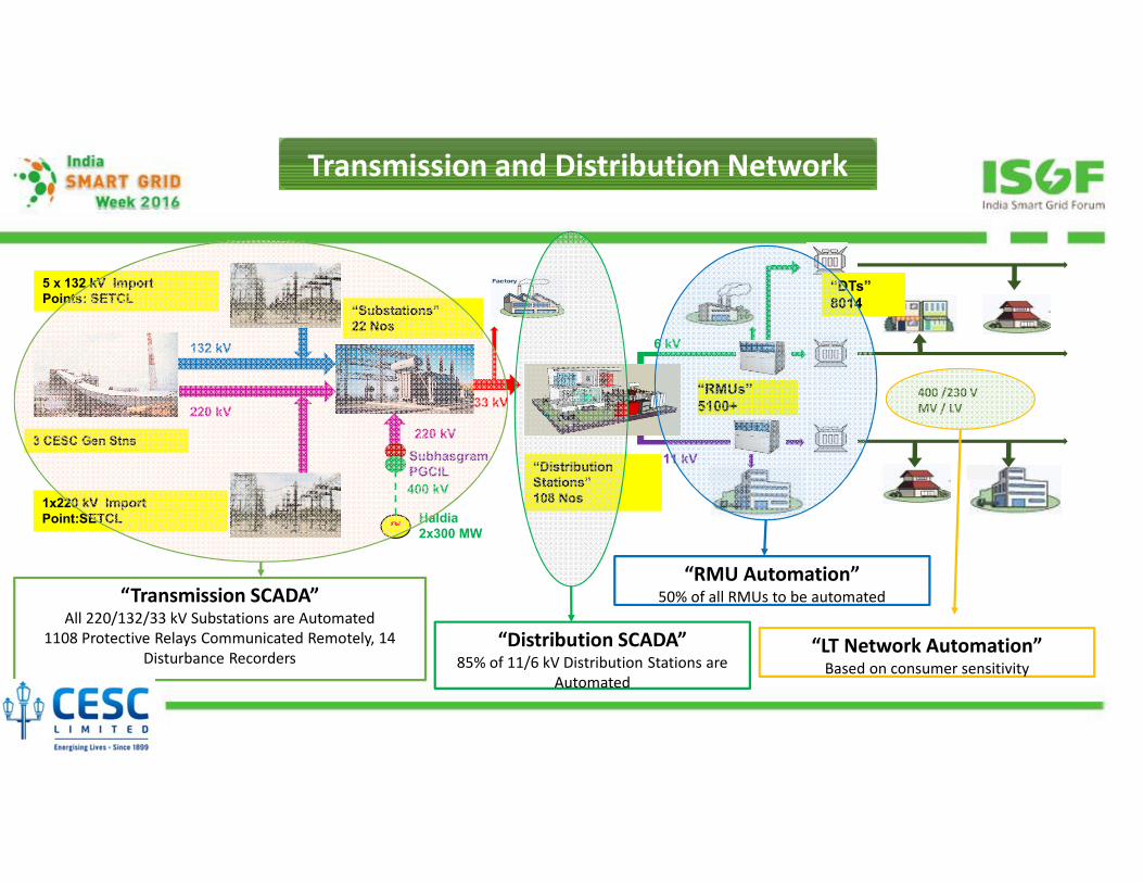
Transmission and Distribution Network
6 kV
11 kV
33 kV
132 kV
220 kV
“Substations”22 Nos
“Distribution Stations”108 Nos
“DTs”8014
5 x 132 kV ImportPoints: SETCL
3 CESC Gen Stns
400 /230 VMV / LV
“RMUs”5100+
1x220 kV ImportPoint:SETCL ~
Haldia2x300 MW
400 kV
SubhasgramPGCIL
220 kV
“Transmission SCADA”All 220/132/33 kV Substations are Automated
1108 Protective Relays Communicated Remotely, 14 Disturbance Recorders
“Distribution SCADA”85% of 11/6 kV Distribution Stations are
Automated
“RMU Automation”50% of all RMUs to be automated
“LT Network Automation”Based on consumer sensitivity

4
The LV network forms the last mile network connectivity for an overwhelming majority of ourconsumers
LV network topology: Open ring main with single point neutral earthing.
Overview of LT Network in CESC

5
Challenges in LT Network
• The LV network was a relatively neglected domain until recently.
• In the year 2011-2012, the organisation shifted its focus to LV distribution network.
• The major pain points faced in LT network are:• Distributed nature of the network and poor network visibility.
• High frequency of supply outages due to Fusing and Faults.
• Existence of Low Voltage Pockets
• Paucity of space for installation of network assets.
• High turn around time for sensitive LV consumers.
• These pain points, coupled with the organisational urge to ensure that our consumers haveaccess to better quality of power at cheaper costs motivated us to revisit our traditionalpractices pertaining to LV distribution network.

LT Network Automation
LT Control Room
LT Pillar Box with MFMs
Consumer end Power Fail Indicator
LT Auto-change-over System
over SMS
over OFC
over SMS
Call Centre with LT Outage Details
GIS based LT Outage Management
• GIS-centric LT Control Room• Field Force equipped with Tabs

7
Objectives of LT Network Automation
Less Outage Duration in LT
Network
Less Outage Duration in LT
Network
Constant Supply Monitoring of
Important Consumers
Constant Supply Monitoring of
Important Consumers
Energy Audit Operations
Energy Audit Operations
Loss Control Measures
Loss Control Measures
Supply Monitoring during important
events and festivals
Supply Monitoring during important
events and festivals

8
Projects
Smart Re-Engineered Pillar BoxesSmart Re-Engineered Pillar Boxes
Smart Pillar Box AutomationSmart Pillar Box Automation
LT Power Failure IndicatorLT Power Failure Indicator
LT Compact SubstationsLT Compact Substations
Smart LT Auto-Changeover SystemsSmart LT Auto-Changeover Systems
Crew Management for Field- force automationCrew Management for Field- force automation

9
Problems Faced in Conventional Pillar Boxes:
• Protection: No. 14 SWG Copper wire
• High frequency of fusing
• Rewireable copper fuses prone to failure due to ageing.
• Fusing current a function of Skill of workmen.
• Live line Operation: Safety Hazard
Re engineered Pillar Boxes:• Compact design: Operation only from the front.
• HRC fuses in place of rewireable fuse wires.
• Better reliability of supply
• Fuse replacement does not require skill.
• HRC fuses ensures safety in operation
• Nearly 11200 Pillar Boxes installed till date
Smart Re-engineered Pillar Box

10
Pillar Box Automation
• Installation of Automation Unit in Re-engineered Pillar Box.
• Proactive information in case of Fusing through SMS alerts.
• Pinpointed information of Fusing.
• Faster restoration of supply in case of outage.
• Reduction in Process Cycle Time.
Remote monitoring of Pillar Boxes
• CTs installed on cable cores.
• Electrical Parameters transmitted to remote control centre through RTUs via Fibre Network
• Proactive remedial action.
• Pilot project done for pillar boxes supplying to major Durga Puja pandals in Kolkata
Automated Pillar box
SMART Pillar Box Automation

11
O/F Network
RMUFRTU
Pillar Box
Pillar Box
MFM Box
DMS at Control
Centre
Existing RMU Automation System
IEC 60870-5-104
Modbus I/O s
CTs, Ph-Volts
CTs, Ph-Volts
SMART Pillar Box Automation

12
Fuse Fail Contacts
Door Open Contact
Consumer Service Point
Auckland Square
LT Control Room
Packet Switched Gigabit Ethernet Network
LT Pillar Box Monitoring System
SMS Gateway
SMS Server/ Web Server
GSM Network
Internet Cloud
LT Power Failure Indicators

13
SMS to GUI Conversion Scheme

14
Pains associated with Low Voltage Pockets
• Low Voltage pockets crop up in our distribution network mainly due to OverloadedTransformers, Long Distributors and High Concentration of Reactive Loads.
• Pockets are eliminated by CAPEX intensive processes of LV network remodelling andcommissioning of new transformers.
• Traditional methods make little economic sense for smaller pockets.
The way out: LTCSS
• LTCSS comprises of a Voltage Regulator and a capacitor bank, installed individually or in acombination at strategic points.
• It is an Autotransformer, in conjugation with a capacitor bank to compensate internalreactive power requirement.
• Suited for low voltages due to long length of distributor.
• Capacitor banks are also installed in areas with Reactive loads which reduces line losses bymodulating the reactive current.
Voltage Regulator
Low Voltage Compact Substations

15
• Aimed at reduction of turnaround time for supply failure forsensitive LV consumers.
• Two feeds are kept ready at supply point for automatic changeoverfrom one to the other in case of supply failure.
• The two feeds are obtained from different MV sources, which arefed from separate power transformers.
• Practically Uninterrupted supply & increased customer satisfaction.
• Also as the supply is being changed over SMS alerts are generatedand sent to predefined mobiles.
Smart LT Auto change-over Systems

16
Crew management in managing customer complaints
• Aimed at reducing the movement of front end personnel
• Front end personnel supplied with APPs loaded smart phones enabling acceptance of customer complaints and providing feedback on the go.
• Reduction of Process Cycle time.
• Minimisation of Error due to manual intervention in the process.
Process flow for Crew Management System
Crew Management for Field-force Automation

17
Technical Loss Minimisation
Enhanced Customer satisfaction
Improved Network Performance
Cost Savings
Benefits

18
• Large-scale rollout of LT Pillar Box Automation in the coming fiscals.
• LT Voltage Imbalance Auto Correction Techniques
• Smart Metering (AMI) of a large section of the consumer base in Kolkata city
• Need based deployment of LT Power Failure Indicator & Smart Auto Changeovers
Roadmap of LT Network Automation

“THANK YOU”