experiment 21: geometric optics - university of mississippi · experiment 21: geometric optics...
TRANSCRIPT

Experiment 21: Geometric Optics
Figure 21.1: Geometric Optics Equipment
Figure 21.2: Mirror Placement: The “Plexi-Ray Kit” contains a small piece of cork or plastic to stabilize the mirrorduring your experiment. The mirror must sit on the paper, not on the stabilizer.
EQUIPMENT
Plexi-Ray KitCorkboardPaper (9 sheets per 2-member team)(2) Protractors(2) 30-cm Rulers(2) White Pins(2) Color PinsLens Cleaning Towelettes (TA’s Table) - optical elements may need to be cleaned
119

120 Experiment 21: Geometric Optics
Advance Reading
Text: Geometric optics, law of reflection, law of refrac-tion, index of refraction, total internal reflection, criti-cal angle, parallax, real image, virtual image, speed oflight.
Objective
The objective of this experiment is to study the be-havior of light using the ray model.
Theory
We will investigate light reflecting from objects as wellas light that is transmitted through objects.
An image viewed in mirror is a virtual image as areimages for some lenses. Light rays do not actuallypass through a virtual image. A virtual image cannotbe projected on a screen. The image seen in a mirrordoes not appear to be at the surface of the mirror, butrather to be located some distance behind the surface.The image appears to be located the same distancebehind a plane (flat) mirror as the object is in frontof the mirror. We investigate virtual images for planemirrors in Part 1 and Part 2 of this experiment; wewill investigate virtual images from a lens in Experi-ment 22.
The Law of Reflection states that when light reflectsfrom a smooth, flat surface (e.g., a plane mirror), theangle of incidence equals the angle of reflection:
✓i
= ✓r
(21.1)
In geometric optics, all angles are measured with re-spect to the normal (the perpendicular). We investi-gate this law in Part 3 of this experiment.
When light passes from a vacuum into a transparentmedium, it slows down. The ratio of the speed of lightin a vacuum, c, to the speed of light through a trans-parent medium, v, is the index of refraction, n, ofthat medium. n � 1 at all times, since:
n =c
v(21.2)
The speed of light in a vacuum, c, has been defined:299,792,458 m/s, or approximately 3⇥ 108 m/s. Notethat each material has its own index of refraction; n isa property of the medium.
Figure 21.3: Refraction
The Law of Refraction (Snell’s Law) describes thebehavior of a ray of light that passes from one mediuminto another:
n1 sin ✓1 = n2 sin ✓2 (21.3)
where n1 and n2 are the indices of refraction for thetwo media, ✓1 is the angle of incidence, and ✓2 is theangle of refraction. We investigate the law of refractionin Part 4 of this experiment.
Total Internal Reflection is a special case in whichlight is unable to cross the boundary between the twomedia. Consider Eq. 21.3 and a specific combination ofmedia, such as glass and air, with light passing througha medium of higher n (n1) into a medium of lower n(n2). As ✓1 increases, ✓2 increases more rapidly. ✓1can reach a value that results in ✓2 being equal to 90�.When this happens, the light will not exit the medium.It will be totally internally reflected. This ✓1 angle iscalled the critical angle, ✓
C
:
✓1 = ✓C
when ✓2 = 90� (21.4)
Note that each combination or media can have a dif-ferent ✓
C
. Note also that total internal reflection onlyhappens when light passes from a medium of higherindex of refraction into a medium of lower index ofrefraction. Total internal reflection is a part of our ev-eryday world - fiber optics, for example, used for cableTV. We investigate total internal reflection in Part 5of this experiment.

Experiment 21: Geometric Optics 121
Parallax is the e↵ect whereby the position or directionof an object appears to di↵er when viewed from di↵er-ent positions. This means that the object and the twoobservations points are not collinear. Fig. 21.4 andFig. 21.5 represent the e↵ect.
The apparent change in direction can be useful for de-termining the distance from Earth to a star. The dia-gram below is, of course, not to scale.
Figure 21.4: Parallax - One Object
Parallax is larger when the object is closer. Whileparallax can present problems when making measure-ments, it is very useful for determining the position ofa virtual image.
Consider two objects that are aligned from your ini-tial position (they appear to be one object). Whenyou change your position, each object will appear tobe displaced but by a di↵erent amount. The objectsappear to separate (Fig. 21.5). They are no longeraligned with your position.
Figure 21.5: Parallax - Two Objects
We make use of parallax (2 objects) in Part 1 and, ifyou so choose, Part 2 of this experiment.
Since a virtual image cannot be projected on a screen,it can be di�cult to determine its location. Consideran object whose image is observed in a mirror. Theimage is a virtual image. To determine the positionof a virtual object, one can align a real object (pin)with a virtual object (image of a di↵erent pin). If theobserver changes their position and the two objects donot separate, the real and virtual objects are in thesame location.

122 Prelab 21: Geometric Optics
Name:
1. State the law of reflection. Write the equation. (10 pts)
2. State the law of refraction. Write the equation. (10 pts)
3. What is the definition of a virtual image? (10 pts)
4. What is total internal reflection? (10 pts)
5. Define critical angle. (10 pts)
6. Define parallax. (10 pts)
7. Write Snell’s Law. Using Eq. 21.4, derive the equation for the critical angle: ✓C
= . (40 pts)

Experiment 21: Geometric Optics 123
PROCEDURE
1. Read through Step 6 before beginning. All arrange-ments (paper) should be aligned with the edge ofthe table.
2. Measure all normal lines with a protractor to ensurethey are 90�; do not estimate. Draw the lines longenough to allow accurate measurements using theprotractor. Do not fold the paper!
3. When placing more than one pin, separate them asmuch as possible (e.g., one pin close to the mir-ror, the other pin close to the edge of the paper).This will increase accuracy and improve your re-sults. When aligning objects and images, close oneeye.
PART 1: Parallax
4. For Part 1, you will use a virtual image (the mirrorimage of a pin); use the image of the white pin asthe first object and a real object (a color pin) as asecond object. If the second object is placed at alocation other than the location of the first object,note that when you change your position there isa shift in the apparent position of the two objects.You will see two images (Fig. 21.5); they will notbe aligned.
5. When parallax occurs, there are two possibilities:
• The pin is in front of the virtual image. Par-allax is larger for the pin.
• The pin is behind the virtual image. Parallaxis smaller for the pin.
6. If the pin is placed at the same location as the vir-tual image and you change your position, there willbe no change in the apparent position of the twoobjects (i.e., there will be no separation of the ob-jects). You will see only one image, thus eliminatingparallax.
Figure 21.6: Parallax
7. Refer to Fig. 21.6. Draw a line across the center ofa sheet of paper (baseline) and a line normal to thebaseline down the center of the paper.
8. Place the paper on the corkboard and place theback of the mirror on the baseline (Fig. 21.2). Placea white pin midway on the normal in front of themirror. The image of this pin will be object 1.
9. Place a color pin on the normal behind the mirror.This pin will be object 2.
10. Observe from an orientation to the right or left ofthe normal. If object 1 and object 2 are not aligned,move object 2 towards or away from you, along thenormal, until they are aligned. (Your partner willhelp you stay on the normal.)
11. Measure and record the distance from the mirror tothe white pin, d0, and the distance from the mirrorto the second pin, d
i
.

124 Experiment 21: Geometric Optics
PART 2: Image from a Mirror
12. Team performs once; take turns for each vertex.
13. Refer to Fig. 21.7. Draw a baseline across the centerof a sheet of paper. Place the triangular plexiglassin the center of the front half of the paper, tracearound it, then return it to the kit. Label the ver-tices of the triangle A, B, and C. Place the paperon the corkboard and the mirror on the baseline.
14. You may use either the parallax method or the fol-lowing method to determine the position and di-mensions of the virtual image of the triangle.
15. Consider Fig. 21.7. Two points are required to des-ignate a particular line (e.g., two a0 or two a00).(Always separate the pins as much as possible toimprove your results.) Two intersecting lines desig-nate a particular point (e.g., A0).
Figure 21.7: Image from a Mirror
16. Place a white pin at vertex A; the image of thewhite pin is the object. Observe from the left andalign two color pins (sighting pins) with the object.
17. Mark the positions, then remove the pins and labelthe positions of the sighting pins a0.
18. Repeat, observing from the right. Mark the sightingpin positions as a00.
19. Repeat for vertices B and C (obtaining two sightlines for each vertex).
20. Draw a line through the two a0 points, the lengthof the paper. Repeat for each pair of points. Markthe intersection of the a0 and a00 lines as A0. Repeatfor B0 and C 0.
21. Connect the points A0, B0, and C 0. Measure andcompare the dimensions of the object and imagetriangle.
PART 3: Reflection
22. Refer to Fig. 21.8. Draw a baseline across a sheetof paper, near the top. Draw a line normal to thebaseline down the center of the paper. Draw a lineto the left of the normal (incident line) with angle✓i
between 25� and 35�.
Figure 21.8: Reflection
Experiment 21: Geometric Optics 125
23. Place the two white pins on the incident line. Labelthese positions P1 and P2.
24. Look at the mirror from the right side of the normalso that you can see the image of the first two pins.Adjust your position so that the images of the whitepins are aligned; align two color pins with them.
25. Label these two points P3 and P4.
26. Draw a line connecting point P3 and P4 to the base-line. Measure and record ✓
i
and ✓r
.
PART 4: Refraction
27. Place the plexiglass square at the center of a sheetof paper and trace around it.
28. In the upper-left corner of the traced square, drawa line normal to the square, about 2 cm from thecorner (Fig. 21.9).
29. Draw an incident line (✓ between 25� and 35�).Place the paper on the corkboard, the square on itstraced outline, and two white pins on the incidentline. Label their positions P1 and P2.
30. Look through the plexiglass square from the edgeopposite the pins and close your left eye. (It willhelp if your partner holds a piece of paper behindthe square to block images of other objects in theroom.)
31. Adjust your position until the two white pins arealigned, then place two sighting pins (color pins)that align with the image of the two white pins.Label these points P3 and P4.
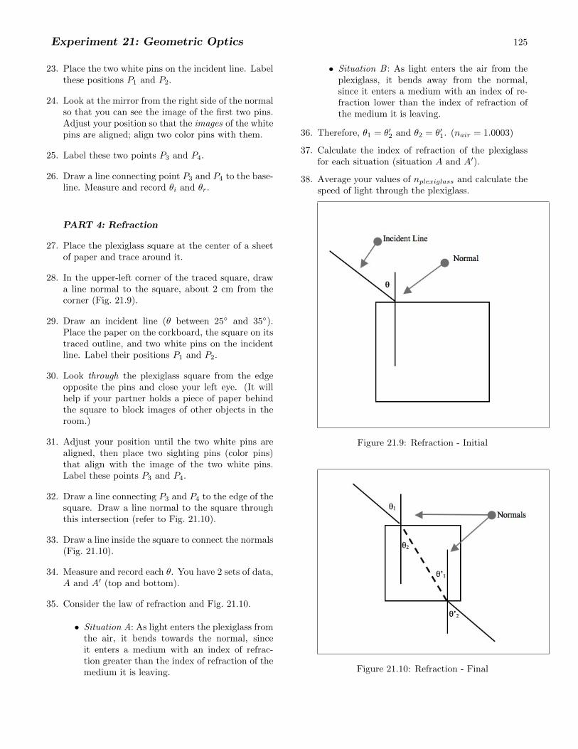
32. Draw a line connecting P3 and P4 to the edge of thesquare. Draw a line normal to the square throughthis intersection (refer to Fig. 21.10).
33. Draw a line inside the square to connect the normals(Fig. 21.10).
34. Measure and record each ✓. You have 2 sets of data,A and A0 (top and bottom).
35. Consider the law of refraction and Fig. 21.10.
• Situation A: As light enters the plexiglass fromthe air, it bends towards the normal, sinceit enters a medium with an index of refrac-tion greater than the index of refraction of themedium it is leaving.
• Situation B : As light enters the air from theplexiglass, it bends away from the normal,since it enters a medium with an index of re-fraction lower than the index of refraction ofthe medium it is leaving.
36. Therefore, ✓1 = ✓02 and ✓2 = ✓01. (nair
= 1.0003)
37. Calculate the index of refraction of the plexiglassfor each situation (situation A and A0).
38. Average your values of nplexiglass
and calculate thespeed of light through the plexiglass.
Figure 21.9: Refraction - Initial
Figure 21.10: Refraction - Final

126 Experiment 21: Geometric Optics
PART 5: Total Internal Reflection
39. Place the plexiglass triangle in the center of a sheetof paper and trace around it. Draw a line normal tothe bottom edge (the long side), about 1 cm fromthe left corner (Fig. 21.11). Place the paper andtriangle on the corkboard; place two white pins onthe normal line with their positions labeled P1 andP2.
40. Look through the right side of the bottom edge ofthe triangle and adjust your position until the twowhite pins are aligned. (It will help if your partnerholds a piece of paper behind the triangle to blockimages of other objects in the room.) Now align twocolor pins with the white pins as viewed through theplexiglass. Label these position P3 and P4.
41. Return the triangle and pins to the kit; place thepaper on the table.
42. Draw the path of the light ray by:
• Extending the normal (P1P2) to the far edgeof the triangle
• Connecting P3 and P4, extending the line tothe far edge of the triangle
• Connecting the line segments (P1P2 to P3P4)at the top (far edges of the triangle)
43. Draw a line normal to the edge of the triangle whereeach light ray (P1P2 and P3P4) intersects the faredge of the triangle.
44. Measure ✓1 and ✓2 at each location where the lightreflects internally. You have two sets of data, A andA0 (right and left).
Figure 21.11: Total Internal Reflection
QUESTIONS
1. Calculate ✓C
for plexiglass in air (using your aver-age value of “n” from Part 4).
2. What is the shortest height a plane mirror must beso that a person who is 1.6 meters tall is able tosee his or her whole body? Draw a ray diagram tosupport your answer.