experiment 26 reflection and refraction
TRANSCRIPT

Experiment 26 Reflection and Refraction Advanced Reading: University Physics Vol.3 by OpenStax, Chapter 1 Section 1.2-1.4 and Chapter 2 Section 2.1. Equipment: 1 Plexi-Ray kit 2 corkboards 2 protractors 2 30 cm rulers Objective: The object of this experiment is to study the phenomena of reflection, virtual image formation, refraction and total internal reflection. Theory:
The Law of Reflection states that the angle of the incident ray equals the angle of the reflected ray, or . See Figure 26-1. In this experiment the formation of a virtual image by a plane mirror will examined. A virtual image is an image that cannot be projected on a screen, but the image can be seen by the eye (e.g., the image from a plane mirror).
Figure 26 -1
In general the speed of light in any material is less that the speed of light in a vacuum, so the index of refraction defined as the ratio
and is always greater than or equal to one.
The Law of Refraction (Snell's Law) relates how a ray of light will behave when passing from one media to the other. It is given by Eq. 26-1
Optical ray kit used in lab
where and are the indices of refraction for the two different media and and are the angles measured with respect to a line normal to the interface. If < the refracted ray bends towards the normal. See Figure 26-2.
If > the refracted ray bends away from the normal.
θi = θr
n ≡ speed of light in vacuum
speed of light in medium=cv
n1 sinθ1 = n2 sinθ2
n1 n2θ1 θ2
n1 n2
n1 n2
Figure 26-2 (Image from A+ Physics webpage)
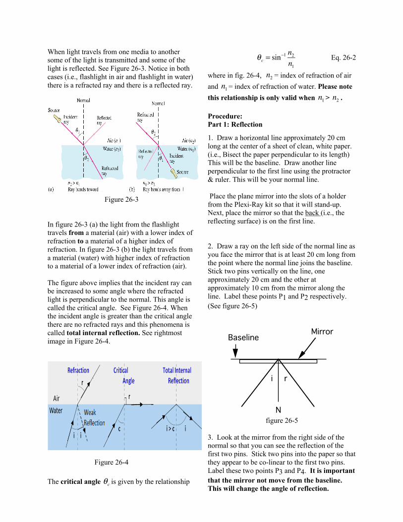
When light travels from one media to another some of the light is transmitted and some of the light is reflected. See Figure 26-3. Notice in both cases (i.e., flashlight in air and flashlight in water) there is a refracted ray and there is a reflected ray.
Figure 26-3
In figure 26-3 (a) the light from the flashlight travels from a material (air) with a lower index of refraction to a material of a higher index of refraction. In figure 26-3 (b) the light travels from a material (water) with higher index of refraction to a material of a lower index of refraction (air). The figure above implies that the incident ray can be increased to some angle where the refracted light is perpendicular to the normal. This angle is called the critical angle. See Figure 26-4. When the incident angle is greater than the critical angle there are no refracted rays and this phenomena is called total internal reflection. See rightmost image in Figure 26-4.
The critical angle is given by the relationship
Eq. 26-2
where in fig. 26-4, = index of refraction of air and = index of refraction of water. Please note this relationship is only valid when > . Procedure: Part 1: Reflection
1. Draw a horizontal line approximately 20 cm long at the center of a sheet of clean, white paper. (i.e., Bisect the paper perpendicular to its length) This will be the baseline. Draw another line perpendicular to the first line using the protractor & ruler. This will be your normal line. Place the plane mirror into the slots of a holder from the Plexi-Ray kit so that it will stand-up. Next, place the mirror so that the back (i.e., the reflecting surface) is on the first line. 2. Draw a ray on the left side of the normal line as you face the mirror that is at least 20 cm long from the point where the normal line joins the baseline. Stick two pins vertically on the line, one approximately 20 cm and the other at approximately 10 cm from the mirror along the line. Label these points P1 and P2 respectively. (See figure 26-5)
figure 26-5
3. Look at the mirror from the right side of the normal so that you can see the reflection of the first two pins. Stick two pins into the paper so that they appear to be co-linear to the first two pins. Label these two points P3 and P4. It is important that the mirror not move from the baseline. This will change the angle of reflection.
θc
θc = sin−1 n2n1
n2n1
n1 n2
MirrorBaseline
N
.i r
Figure 26-4

4. Draw a line that connects points P3 and P4. Measure the angle of incidence and the angle of reflection and compare to theory. 5. Repeat steps 2-4 for another set of points. Part 2: Refraction. 6. Place the plexiglass (or glass square) at the center of another sheet of clean white paper and trace around it. In the upper-left corner of the traced square, draw a line normal to the square 1 cm from the corner of the square that crosses the side of the square. (see figure 26-6).
Figure 26-6 7. Draw a line left of the normal and place pins on the line as done in part 1 of this experiment. Look through the plexiglass square from the side opposite pins and place pins two pins in the page so that it appears that all the pins are collinear. Label these two points P3 and P4. Take the pins out and draw a line through the points beginning at the edge of the square. Where the line joins the edge of the square, draw another normal line that crosses the side of the edge of the square. 8. Measure the angles that the incident and transmitted (refracted) ray makes to the normal N when the ray enters the block. Repeat these measurements for the ray as it leaves the block Use these angles to calculate the index of refraction of the material. See Figure 26-6. 9. Repeat for a different set of points.
Part 3 Total Internal Reflection 10. Place the plexiglass triangle on a sheet of paper and trace around the edges. Put two pins in the page at points and such that the line defined by the 2 points is perpendicular to the base of the triangle. (See Figure 26-7)
figure 26-7
11. Stick two more pins into the page so that all four pins appear co-linear. Remove the triangle from the page and draw rays showing the path of the light ray. (The result may be surprising.) Part 4 Image from a plane mirror 12. The image seen in any plane mirror does not appear to be at the surface of the mirror, but rather, to be located some distance behind the surface This image is known as a virtual image. The image appears to be located the same distance behind the mirror as the object is in front of the mirror. (See figure 26-8) 13. Draw a line bisecting a sheet of clean, white paper. Place the triangular plexiglass in the middle of one of the bisected halves and trace around it. Remove the triangular piece. Label the vertices A, B, C. Place the mirror on the line bisecting the paper with the silvered surface exactly on the line. See figure 26-8.
N
N
i
r
r
i
P1 P2
.
.P1
P2

14. Stick a pin into the cork board at the vertex labeled A and from a point of observation, use two more pins to mark a sight line to the image of the point A pin. Remove the sighting pins and mark the pin pricks with an 'a'. Repeat this again from a different observation point. Do this again for the pins a vertices B and C, obtaining two sight lines for each vertex. (see figure 26-8) 15. Remove all the pins and the mirror. Draw a line connecting the first two 'a' pin pricks, extending the line fully across the page. Do this for all pairs of pin pricks. Mark the intersection of the 'a' lines with an A' and the intersection of the 'b' and 'c' lines with a B' and C' respectively. 16. Connect the point A', B', and C'. Measure the dimensions of the virtual image and compare the dimensions with the object triangle.
Figure 26-8
A B
Ca'
a'
a'
a'
A' B'
C' Mirror
Object
Image

Experiment 26 Reflection and Refraction
Worksheet Section: _______ Name: ___________________
Lab Procedure: (Attach the sheets of paper that you draw the ray diagrams to the end of this worksheet)
Part 1: Law of Reflection Record the incident and reflected angles including the uncertainty of the angles in your measurement.
Does the angle of incidence equal the angle of reflection in this experiment? Uncertainty should be considered. Discuss your results.
Part 2: Index of Refraction
Record the four sets (2 sets each when light enters and leaves the block) of index calculation along with the uncertainties. (You can find an example of the uncertainty calculation in the additional file. For a group of 2, each lab partner should calculate two sets of data.)
Ray 𝜃! 𝜃" n 𝛿𝑛 1 2 3 4
What is the average value for the index? navg = ___________________
Part 3: Total Internal Reflection 1. Use the index of the plexiglass you measured in part 2 and calculate the critical angle of total internal reflection 𝜃# . Show all of your steps. 2. What are the incident angles you measured in the experiment? Label the two incident angles you measured on the right diagram. Are those incident angles larger or smaller than the critical angle of total internal reflection that you calculated?
Part 4: Image from a Plane Mirror Record the side lengths and the angles of the image that you measured in the table below. (Use the labels as shown in the diagram on the right.)
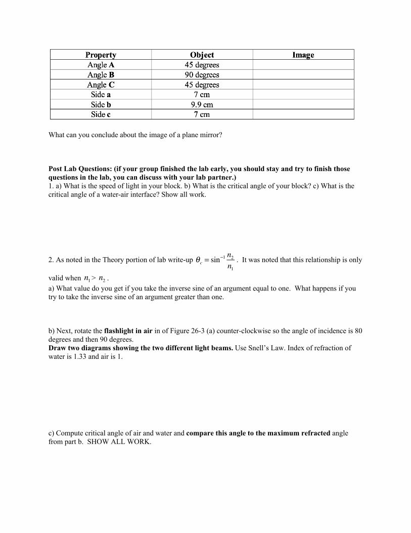
What can you conclude about the image of a plane mirror? Post Lab Questions: (if your group finished the lab early, you should stay and try to finish those questions in the lab, you can discuss with your lab partner.) 1. a) What is the speed of light in your block. b) What is the critical angle of your block? c) What is the critical angle of a water-air interface? Show all work.
2. As noted in the Theory portion of lab write-up . It was noted that this relationship is only
valid when > . a) What value do you get if you take the inverse sine of an argument equal to one. What happens if you try to take the inverse sine of an argument greater than one. b) Next, rotate the flashlight in air in of Figure 26-3 (a) counter-clockwise so the angle of incidence is 80 degrees and then 90 degrees. Draw two diagrams showing the two different light beams. Use Snell’s Law. Index of refraction of water is 1.33 and air is 1. c) Compute critical angle of air and water and compare this angle to the maximum refracted angle from part b. SHOW ALL WORK.
θc = sin−1 n2n1
n1 n2

3. Continue with the simulation that you did in the prelab There is a “Mystery B” material provided in the simulation, try to set up this simulation and do some measurements to figure out what this material is. Describe your method (step by step approach of how you designed this virtual lab) and your result below. (For this problem, if you discussed with your lab partner, you can compare whose plan is easier to do and whose plan is more accurate.) 4. Also use the simulation, learn about Intensity. Set the simulation to any combination of materials and incident angle you like. Click and pull the Intensity Reader to read the intensity of the incident beam, the reflected beam and the refracted beam. Record your reading here: (try two different settings) Trail 1: Intensity reading of the incident light ________; Intensity reading of the reflected light _______; Intensity reading of the refraction light ________; Trail 2: Intensity reading of the incident light ________; Intensity reading of the reflected light _______; Intensity reading of the refraction light ________; What can you conclude about the relation between the energy intensities of those three lights? Now put the setting to when total internal reflection happens at around the critical angle. Measure how the energy intensity of the reflected light and the refracted light changes when the angle is around the critical angle. What can you conclude?