experiment 6 - ieu.edu.trhomes.ieu.edu.tr/maskar/eee331/lab/eee331-exp-6n.pdf · eee 331 analog...
TRANSCRIPT
6-1
İzmir University of Economics EEE 331 Analog Electronics - Lab
EXPERIMENT 6 Power Amplifiers
A. Background Class A Stage
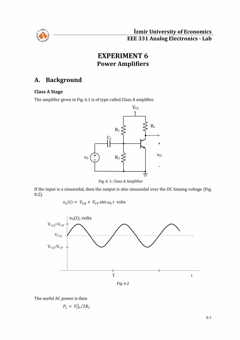
The amplifier given in Fig. 6.1 is of type called Class A amplifier.
If the input is a sinusoidal, then the output is also sinusoidal over the DC biasing voltage (Fig. 8.2).
volts
Fig. 6.2
The useful AC power is then
vO(t), volts
VCQ
T t
VCQ+VCP
VCQ-VCP
vS
+
vO -
R2
R1 RL
VCC
C1
Fig. 6. 1. Class A Amplifier
6-2
For the power delivered to the circuit, the power spent over the base circuitry is neglected and the average power delivered from the power supply is obtained as:
The power efficiency is defined as
or
The maximum efficiency is reached if
and and
Under these conditions, the efficiency becomes:
i.e.., the 25 percent of the power delivered to the circuit is obtained as useful load power.
Class B Stage
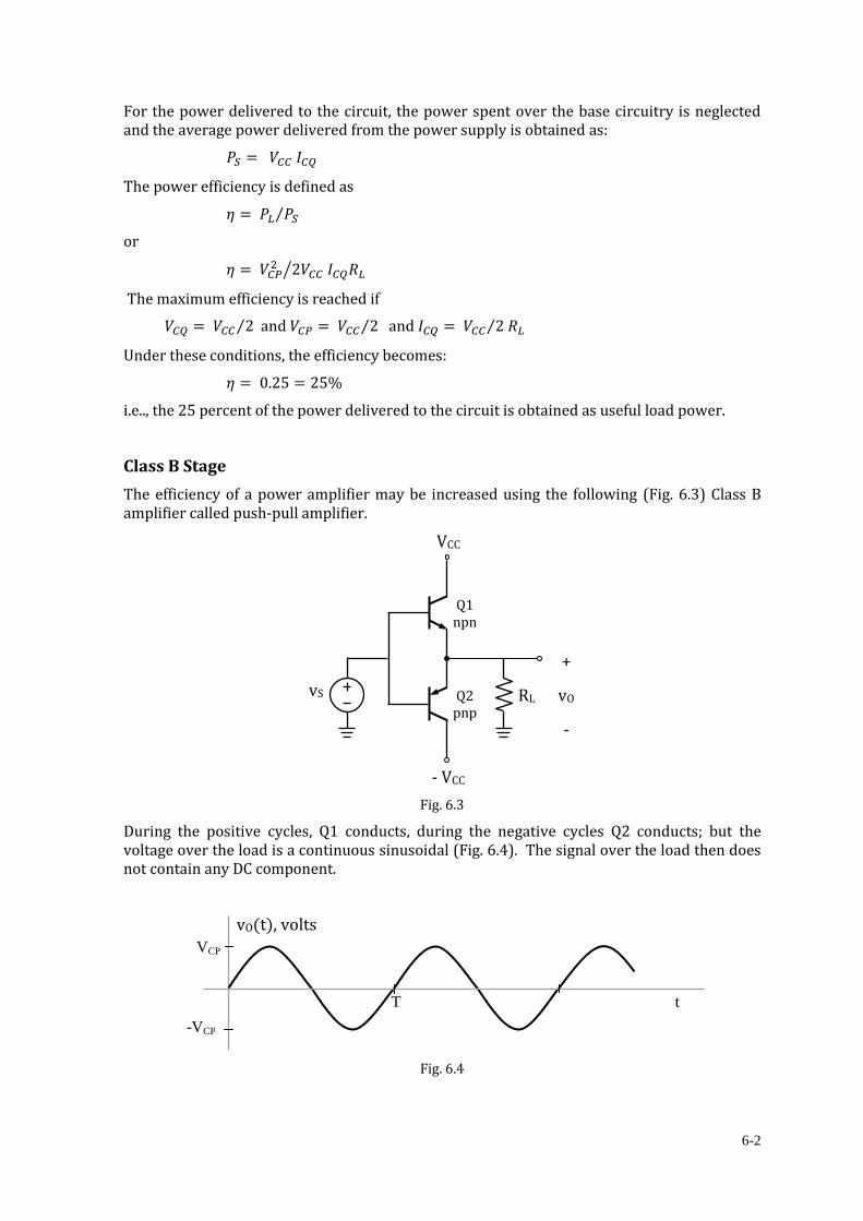
The efficiency of a power amplifier may be increased using the following (Fig. 6.3) Class B amplifier called push-pull amplifier.
Fig. 6.3
During the positive cycles, Q1 conducts, during the negative cycles Q2 conducts; but the voltage over the load is a continuous sinusoidal (Fig. 6.4). The signal over the load then does not contain any DC component.
Fig. 6.4
vO(t), volts
T t
VCP
-VCP
vS
+
vO
-
RL
VCC
- VCC
Q1 npn
Q2 pnp

6-3
For the Class B amplifier then
and the power from the above power supply proportional to VCC and the average current through the collector of Q1.
The collector current of Q1 is a half-wave rectified sine wave (Fig. 6.5).
Fig. 6.5
The average (DC) value of the collector current is then
or
and
The total power from the two sources is therefore
Hence the efficiency is
As it can be seen from the above result, the efficiency is linearly proportional to VCP. The maximum efficiency is reached when VCP = VCC, then
Class AB Amplifier
Because of the turn-on voltages of base-emitter junctions of the transistors, the output voltage is distorted and not a pure sine wave (Fig. 6.6). This distortion is called cross-over distortion.
Fig. 6.6
vO(t), volts
T t
VCP – VBE1(on)
-VCP + VEB1(on)
iC1(t), volts
T t
ICP
ICP= VCP/RL
6-4
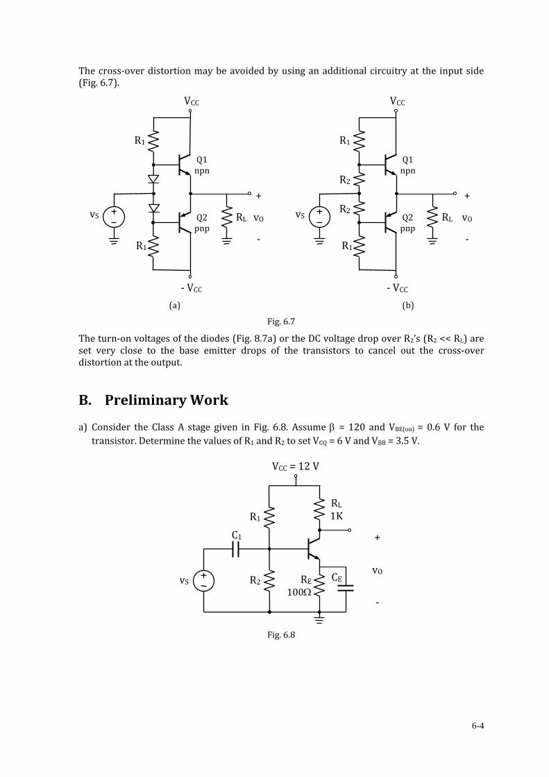
The cross-over distortion may be avoided by using an additional circuitry at the input side (Fig. 6.7).
(a) (b)
Fig. 6.7
The turn-on voltages of the diodes (Fig. 8.7a) or the DC voltage drop over R2’s (R2 << RL) are set very close to the base emitter drops of the transistors to cancel out the cross-over distortion at the output.
B. Preliminary Work a) Consider the Class A stage given in Fig. 6.8. Assume = 120 and VBE(on) = 0.6 V for the
transistor. Determine the values of R1 and R2 to set VCQ = 6 V and VBB = 3.5 V.
Fig. 6.8
vS
+
vO
-
R2
R1 RL
1K
VCC = 12 V
C1
RE 100
CE
vS
+
vO
-
RL
VCC
- VCC
Q1 npn
Q2 pnp
R1
R1
R2
R2 vS
+
vO
-
RL
VCC
- VCC
Q1 npn
Q2 pnp
R1
R1

6-5
C. Experimental Work
1. Set up the circuit given in Fig. 6.9 with the resistors you have determined in Preliminary
Work. (CE = 100 F, C1 = 10 F. Be careful with the polarities of the capacitors)
Fig. 6.9
(a) Measure VCQ. If VCQ ≠ 6V, make necessary modifications to set VCQ = 6 V.
(b) Apply a sinusoidal signal to the input at f = 1 kHz.
(c) Measure IS and calculate PS.
IS = ……. mA => PS = VCC IS = …………… mW
(d) Now adjust VCP = 3 V. Plot vO below. What is the maximum VCP that you can get?
VCP(max) = …………. Volts
vS
+
vO
-
R2
R1 RL
1K
VCC = 12 V
C1
BD 135
A
IS
CE RE 100
6-6
(e) Calculate the efficiencies for the following VCP values.
VCP PL PS
3 V
VCP(max)(……..V)
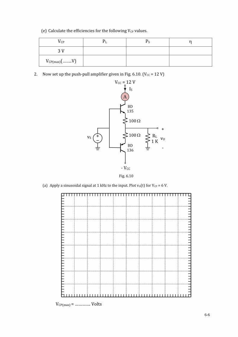
2. Now set up the push-pull amplifier given in Fig. 6.10. (VCC = 12 V)
Fig. 6.10
(a) Apply a sinusoidal signal at 1 kHz to the input. Plot vO(t) for VCP = 6 V.
VCP(max) = …………. Volts
vS
+
vO
-
RL 1 K
- VCC
BD 135
BD 136
100
100
VCC = 12 V
A
IS

6-7
(b) Calculate the efficiencies for the following VCP values.
VCP PL PS
6 V
VCP(max)(……..V)
(c) Set up the following Class AB Amplifier. Apply a sinusoidal signal at 1 kHz to the
input. Plot vO(t) for VCP = 6 V.
Fig. 6.11
vS
+
vO
-
RL 1 K
- VCC
BD 135
BD 136
100
100
VCC = 12 V
R1