experiment document format and instructions for … · experiment document format and instructions...
TRANSCRIPT

Biomedical Systems Test and Project Management Office / SM3
Experiment Document Format and Instructions for Human Life Sciences Flight
Research Experiments
September 2003
CCB CONTROLLED
LS-20079-2A
National Aeronautics andSpace Administration
Lyndon B. Johnson Space CenterHouston, Texas 77058

PROJECT DOCUMENT APPROVAL SHEET
DOCUMENT NUMBER: DATE: NO. OF LS-20079-2A 09/17/03 PAGES: 75
TITLE:
Experiment Document Format and Instructions for Human Life Sciences Flight
Research Experiments
APPROVED: SM3/Michelle Kamman Original Signature on File Flight Experiment Lead
APPROVED: SM/Cindy Haven Original Signature on File Human Life Science Research Program Manager
DATE PREPARED BY CHANGE APPROVALS CHANGE NUMBER
JSC FORM 604 (REV JUL 81) NASA-JSC

DOCUMENT NUMBER
LS-20079-2 DOCUMENT CHANGE/
REVISION LOG PAGE 1 OF 1
CHANGE/ REVISION DATE DESCRIPTION OF CHANGE PAGES
AFFECTED
Basic 06/26/02 Baseline Issue – Reference CCBD: SM3-Temp-0001, HJED-E1-0001, and IJED-D079-2-0001
All
A 09/17/03 Complete Revision. Reference CCBD: HJED-D079-2-0001-001 All
Altered pages must be typed and distributed for insertion. JSC FORM 276 (REV APR 81) NASA-JSC

PROJECT DOCUMENT APPROVAL SHEET
DOCUMENT NUMBER: DATE: NO. OF LS-XXXXX PAGES:
TITLE:
Experiment
Title
APPROVED: Experiment Systems Manager
APPROVED: Principal Investigator
APPROVED: SM3/Program Flight Projects Manager
APPROVED: SM3/Flight Experiment Lead
DATE PREPARED BY CHANGE APPROVALS CHANGE NUMBER
JSC FORM 604 (REV JUL 81) NASA-JSC

Experiment No.: Date:
LS-XXXXX i
TABLE OF CONTENTS
Section Page 1.0 INTRODUCTION 1-1 1.1 PURPOSE 1-1 1.2 SCOPE 1-1 1.3 EXPERIMENT MANAGEMENT APPROACH 1-3 1.3.1 Background 1-3 1.3.2 Human Research Facility 1-3 1.3.3 Documents 1-4 1.3.3.1 Applicable Documents 1-4 1.3.3.2 Reference Documents 1-4 1.3.4 Experiment Support Team Definition 1-5 1.3.5 Experiment Life Cycle 1-6 1.3.5.1 Experiment Definition 1-7 1.3.5.2 Experiment Design 1-8 1.3.5.3 Experiment Implementation 1-11 1.3.5.4 Postflight Reporting and Data Archival 1-13 1.3.6 Flight Experiment Deselection 1-14 1.4 EXPERIMENT DOCUMENT DATA FIDELITY GUIDELINES 1-16 2.0 SCIENCE OVERVIEW 2-1 2.1 SCIENCE OVERVIEW 2-1 2.2 OPERATIONAL OVERVIEW 2-2 2.3 MEASUREMENTS 2-3 2.4 SUPPORTING STUDIES 2-4 2.5 EVALUATION ACTIVITIES 2-5 3.0 DATA COLLECTION REQUIREMENTS 3-1 3.1 GROUND DATA COLLECTION SESSIONS 3-1 3.2 IN-FLIGHT DATA COLLECTION SESSIONS 3-5 3.3 EXPERIMENT BLOCK DIAGRAM 3-9 3.4 DEPLOYED OPERATIONAL ENVELOPE 3-10 3.5 EQUIPMENT LOCATION REQUIREMENTS 3-11 3.6 TEMPERATURE CONTROLLED STOWAGE (REFRIGERATOR, FREEZER) 3-12 3.7 TRASH STOWAGE 3-13 3.8 LIMITED-LIFE AND LATE LOAD/EARLY ACCESS ITEMS LISTS 3-15 3.8.1 Limited Life Items 3-15 3.8.2 Late Load/Early Access Items 3-16 3.9 PHOTO/VIDEO REQUIREMENTS 3-17 4.0 CREW SUBJECT SELECTION, PROFICIENCY AND TRAINING REQUIREMENTS 4-1 4.1 SUBJECT SELECTION 4-1 4.2 CREW SKILL REQUIREMENTS 4-2 4.3 TRAINING REQUIREMENTS 4-3 4.4 TRAINING REQUIREMENTS DEFINITION 4-4 4.5 TRAINING REQUIREMENTS SUMMARY 4-7 4.6 CREW SKILL PROFICIENCY 4-8 5.0 EXPERIMENT FLIGHT SYSTEM REQUIREMENTS 5-1 5.1 EXPERIMENT SYSTEM FUNCTIONAL REQUIREMENTS 5-1 5.2 EXPERIMENT SYSTEM REQUIREMENTS DOCUMENTS 5-2

Experiment No.: Date:
LS-XXXXX ii
TABLE OF CONTENTS (Cont’d)
Section Page 6.0 EXPERIMENT HARDWARE 6-1 6.1 EXPERIMENT FLIGHT HARDWARE 6-1 6.2 BASELINE DATA COLLECTION HARDWARE 6-2 6.3 EXPERIMENT UNIQUE EQUIPMENT SYSTEM DEVELOPMENT SUMMARY 6-3 6.4 MISSION RESOURCE REQUIREMENTS 6-4 7.0 EXPERIMENT SOFTWARE 7-1 7.1 EXPERIMENT SOFTWARE INFORMATION 7-1 7.2 EXPERIMENT FLIGHT SOFTWARE INSTALLATION PLATFORM REQUIREMENTS 7-3 8.0 JSC, KSC GROUND PROCESSING 8-1 8.1 JSC GROUND PROCESSING 8-1 8.2 KSC PROCESSING 8-2 8.2.1 Support Requirements 8-2 9.0 DATA REQUIREMENTS AND MANAGEMENT 9-1 9.1 DATA MANAGEMENT REQUIREMENTS 9-2 9.1.1 Telescience Support Center Data Management Requirements 9-2 9.2 FILE UPLINK/DOWNLINK AND COMMANDING REQUIREMENTS 9-4 9.3 ARCHIVED DATA REQUIREMENTS 9-5 9.3.1 Preflight and Postflight Baseline Data Collection Data 9-6 9.3.2 Investigators Data Analyses 9-7 9.4 MISCELLANEOUS DATA REQUIREMENTS 9-8 10.0 DOCUMENTATION REQUIREMENTS 10-1 10.1 EXPERIMENT MANAGEMENT DOCUMENTATION 10-1 10.1.1 Experiment Management Plan 10-1 10.1.2 Experiment Activities and Milestones Schedule 10-1 10.1.3 Progress Reports 10-2 10.2 SCIENCE SUPPORT DOCUMENTATION 10-2 10.2.1 Human Research Protocol 10-2 10.2.2 Experiment Operating Procedures 10-3 10.2.3 Experiment Manual 10-3 10.2.4 Supporting Studies Impact Reports 10-3 10.2.5 Final Supporting Study Reports 10-4 10.2.6 Science Verification Report 10-4 10.3 EXPERIMENT UNIQUE SOFTWARE DOCUMENTATION 10-4 10.4 SAFETY DOCUMENTATION 10-4 10.4.1 Payload Safety Data 10-4 10.4.2 Payload Ground Safety Data 10-5 10.4.3 Baseline Data Collection Safety Data 10-6

Experiment No.: Date:
LS-XXXXX iii
LIST OF TABLES
Table Page 1.1 EXPERIMENT OVERVIEW 1-2 1.4-1 EXPERIMENT DOCUMENT DATA FIDELITY GUIDELINES 1-16 2.1 SCIENCE OVERVIEW 2-1 2.2 OPERATIONAL OVERVIEW 2-2 2.3 EXPERIMENT MEASUREMENTS 2-3 2.4 SUPPORTING STUDIES 2-4 2.5 EVALUATION ACTIVITIES 2-5 3.1-X GROUND EXPERIMENT SESSION OVERVIEW 3-2 3.2-X IN-FLIGHT EXPERIMENT SESSION OVERVIEW 3-5 3.5-X EQUIPMENT LOCATION REQUIREMENTS 3-11 3.6 TEMPERATURE CONTROLLED STOWAGE 3-12 3.7 TRASH STOWAGE ESTIMATES 3-13 3.8.1 LIMITED-LIFE ITEMS REQUIREMENTS LIST 3-15 3.8.2 LATE LOAD/EARLY ACCESS REQUIREMENTS LIST 3-16 3.9 PHOTO/TV REQUIREMENTS 3-17 4.1 SUBJECT SELECTION REQUIREMENTS 4-1 4.2 CREW SKILL REQUIREMENTS 4-2 4.4-X TRAINING SESSION DESCRIPTION 4-4 4.5 TRAINING SUMMARY 4-7 4.6 CREW SKILL PROFICIENCY 4-8 5.1 EXPERIMENT SYSTEM FUNCTIONAL REQUIREMENTS 5-1 5.2 EXPERIMENT SYSTEM REQUIREMENTS DOCUMENTS 5-2 6.1 EXPERIMENT FLIGHT HARDWARE LIST 6-1 6.2 BASELINE DATA COLLECTION HARDWARE 6-2 6.3 EUE SYSTEM DEVELOPMENT SUMMARY LIST 6-3 6.4 MISSION RESOURCE REQUIREMENTS 6-4 7.1 EXPERIMENT SOFTWARE INFORMATION 7-1 7.2 SOFTWARE INSTALLATION PLATFORM REQUIREMENTS 7-3 8.1 JSC GROUND PROCESSING REQUIREMENTS 8-1 8.2 LAUNCH/LANDING SITE REQUIREMENTS 8-5 9.1.1 TSC DATA MANAGEMENT REQUIREMENTS 9-2 9.1.2 REMOTE SITE DATA MANAGEMENT REQUIREMENTS 9-3 9.2 FILE UPLINK/DOWNLINK AND COMMANDING REQUIREMENTS 9-4 9.3 FLIGHT MEDIA REQUIREMENTS 9-5 9.3.1 PRE AND POSTFLIGHT DATA REQUIREMENTS 9-6 9.3.2 INVESTIGATORS DATA ANALYSES 9-7 9.4 MISCELLANEOUS DATA REQUIREMENTS 9-8 10.1 DOCUMENTATION REQUIREMENTS 10-1

Experiment No.: Date:
LS-XXXXX iv
LIST OF FIGURES
Figure Page 1.3.5-1 Experiment Life Cycle 1-7 3.3.X Experiment Block Diagram 3-9 3.4.X Deployed Operational Envelope Illustration 3-10

Experiment No.: Date:
LS-XXXXX v
ACRONYMS AND ABBREVIATIONS A Ascent AC Alternating Current Acq. Acquisition ACC Personal Access and Training Requirements ADM KSC Administrative Support AEMC Advanced Environmental Monitoring and Control AEVA Advanced Extravehicular Activity AFT Advanced Food Technology AHST Advanced Human Support Technology ALS Advanced Life Support AO Announcement of Opportunity Assoc Associated ATP Authorization to Proceed B Preflight, Preflight BDC, Battery BA Battery BB Biological/Biomedical BDC Baseline Data Collection BP Behavior and Performance bpm bitmap BR&C Biomedical Research & Countermeasures BRP Biological Research Program C Controlled or Ground Control, Compressible ºC Degrees Celsius CBT Computer Based Training CCB Configuration Control Board CD Compact Disc CD-ROM Compact Disk – Read Only Memory CDR Critical Design Review CHE Chemicals CHeCS Crew Health Care System cm Centimeters CO Contracting Officer COM Communications COTR Contracting Officer’s Technical Representative COTS Commercial Off-the-Shelf CP Cardiovascular/Pulmonary CPHS Committee for the Protection of Human Subjects D Descent, Diameter DAT Payload Data Transmission and Recording DFRC Dryden Flight Research Center dpi dots per inch DRD Data Requirements Document E Early; Landing ECG Electrocardiogram ED Experiment Document EEE Electrical, Electronic, and Electromagnetic EMG Electromyogram/Electromyography EMP Experiment Management Plan ERR Experiment Requirements Review ESA European Space Agency

Experiment No.: Date:
LS-XXXXX vi
ACRONYMS AND ABBREVIATIONS (Cont’d) ESM Experiment Systems Manager ESS Experiment Support Scientist EST Experiment Support Team EUE Experiment Unique Equipment EUSW Experiment Unique Software EXP Reusable and Expendable Supplies; Experiment EXPRESS EXpedite the PRocessing of Experiments to Space Station F Final FD Flight Day FDX Flight Day X FEPC Flight Equipment Processing Center FLU Fluid Resources FRD Functional Requirements Document FTP File Transfer Protocol g gravity GASMAP Gas Analyzer System for Metabolic Analysis Physiology GFE Ground Facility Equipment GFS Government Furnished Software GN2 Gaseous Nitrogen GSE Ground Support Equipment GSP Ground Support Personnel H Hard, Height He Helium h/w Hardware HAZ Hazardous Disposal, Storage, and Handling HD Hardware Developer HFM HRF High Fidelity Mockup HLS Human Life Sciences HLS IS HLS Increment Scientist HOB Hardware Onboard HOSC Huntsville Operations Support Center HQ Headquarters (NASA) hr Hour HRD Hardware Requirements Document HRF Human Research Facility HRMRB Human Research Multilateral Review Board HSR Hygiene, Sanitation, Radiation Hz Hertz I In-flight, In-flight ISS IC Increment Coordinator ICD Interface Control Document, Drawing ID Identification IDD Interface Definition Document IDD Interface Design Document IDRD Increment Definition and Requirements Document IIRD Integrated Increment Requirements Document IMN Immunological IP International Partner IPLAT International Payload Label Approval Team IS Increment Scientist

Experiment No.: Date:
LS-XXXXX vii
ACRONYMS AND ABBREVIATIONS (Cont’d) ISC Increment Science Coordinator ISLRA International Space Life Sciences and Space Sciences Research Announcement ISS International Space Station ISSP International Space Station Program IVoDS Internet Voice Distribution System JSC Johnson Space Center kg Kilogram KSC Kennedy Space Center kW Max. Power kWh Energy L Launch, Late, Line, Length L- Launch minus (days before launch) LCD Liquid Crystal Diode LED Light Emitting Diode LLIL Limited Life Item List LSDA Life Sciences Data Archive LSE Laboratory Support Equipment M Monitored, Middeck M/C Monitor/Controlled MCC-H Mission Control Center-Houston MD Middeck MET Mission Elapsed Time, Metabolic min minutes ml milliliter MLE Middeck Locker Equivalent mm millimeter MON Monitoring MP MPLM MPLM Multi-Purpose Logistics Module MRI Magnetic Resonance Imaging MS Musculoskeletal MSDS Material Safety Data Sheet MSFC Marshall Space Flight Center N/A Not Applicable NASA National Aeronautics and Space Administration NEU Neurological NP No Preference NRA NASA Research Announcement NRD Normal Refuse Dry NRT Near Real-Time NRW Normal Refuse Wet NUT Nutritional O On-Orbit Training Obj. Objective OBT On-board Training OFF Offline Processing Area and Electrical Power Requirements OIS-D Operational Intercommunication System, Digital ONL On Line Processing Area and Electrical Power Requirements

Experiment No.: Date:
LS-XXXXX viii
ACRONYMS AND ABBREVIATIONS (Cont’d) OPF Orbiter Processing Facility Ops Operations OTH Other Requirements P Postflight, Preflight, Progress, Preliminary PC Portable Computer PCMCIA Personal Computer Memory Card International Association PCS Portable Computer System PD Payload Developer PDR Preliminary Design Review PE Project Engineer PGSC Payload and General Support Computer PHO Photographic and Video Support PI Principal Investigator POCCB Portable Onboard Computer Control Board POIC Payload Operations and Integration Center PRP Personal Responsibility Program psig Pounds Per Square Inch Gauge PSRP Payload Safety Review Panel PTP Payload Tactical Plan PWQ Process Waste Questionnaire Pwr Power Qty Quantity R Postflight or Rack Mounted R+ Return plus (days after landing) RA Radiation Req’t. Requirement RPO Research Program Office RT Real Time S Stowed, In-flight Shuttle S/W Software S-POCCB Station Portable Onboard Computer Control Board SH Sharps SHFE Space Human Factors Engineering SLF Shuttle Landing Facility SLSD Space and Life Sciences Directorate SOW Statement of Work SP SpaceHab SRD System Requirements Document SSC Space Station Computer SSE Station Support Equipment SSMTF Space Station Mockup and Trainer Facility SSPF Space Station Processing Facility STO Flight Hardware, Ground Support Equipment and Container Storage STE KSC Ground Support Equipment and Special Test Equipment SVT Science Verification Test T Training T/S Transportation/Shipping TF Trichlorotrifluoroethane TRR Test Readiness Review

Experiment No.: Date:
LS-XXXXX ix
ACRONYMS AND ABBREVIATIONS (Cont’d) TSC Telescience Support Center TSS Technical Support Services TTA Technical Task Agreement URC User Requirements Collection U.S. United States USP User Room Area and Electrical Power Support USPCC United States Payload Control Center VAC Volts Alternating Current Vdc Volts Direct Current VDD Version Description Document VHS Video Home System VPN Virtual Private Network W Width, Watt wkstn workstation

Experiment No.: Date:
LS-XXXXX 1-1
1.0 INTRODUCTION
1.1 PURPOSE The Experiment Document (ED) serves the following purposes: a. It provides a vehicle for Principal Investigators (PIs) to formally specify the requirements for
performing their experiments. b. It provides a technical Statement of Work (SOW). c. It provides experiment investigators and hardware developers with a convenient source of
information about Human Life Sciences (HLS) requirements for the development and/or integration of flight experiment projects.
d. It is the primary source of experiment specifications for the HLS Research Program Office (RPO). Inputs from this document will be placed into a controlled database that will be used to generate other documents.
1.2 SCOPE This document establishes and controls requirements for PI activities, selection and training of flight crew members, integration and ground processing of flight experiment equipment, and collection, processing, and archiving of experiment data. The PI is responsible for all of the requirements defined in this ED. National Aeronautics and Space Administration (NASA) representatives will complete the sections/tables identified as “not to be filled out by the PI” (if applicable to the experiment). Following the Experiment Requirements Review (ERR), Preliminary Design Review (PDR), and Critical Design Review (CDR), the entire ED will be presented to the SM3 Configuration Control Board (CCB) for baseline approval. Once the document has been placed under configuration control, any changes to the document will require approval of the SM3 CCB prior to implementation. Table 1.4.1 provides a guideline for the expected fidelity of the data included in the various sections of the ED depending on the review level for the experiment. The activities associated with the various design reviews can be found in Sections 1.3.5.1.3, 1.3.5.2.5 and 1.3.5.2.6.

Experiment No.: Date:
LS-XXXXX 1-2
TABLE 1.1. EXPERIMENT OVERVIEW
Investigation Title: Experiment ID: Ops Name:
Payload Category: Sub-Category: Subjects
Required: Subjects Desired:
Name Address E-mail Fax Telephone Principal Investigator
Co-Investigator Co-Investigator Co-Investigator Co-Investigator
Technical Personnel Technical Personnel
Name and Address of Organization Conducting the Research: Sponsoring Agency:
Instructions for the table entries are provided below: Investigation Title - Title of experiment on original proposal Experiment ID - Identification (ID) assigned by NASA Ops Name - NASA-assigned name, with PI concurrence, for tracking purposes (20 character limit)
NOTE: Preferably, not an acronym, however no strict requirement beyond PI/Experiment Support Team (EST) concurrence.
Payload Category - A code designating the science or technology discipline associated with the investigation. For the purposes of the ED, the only categories currently used within HLS RPO are: BR&C = Biomedical Research & Countermeasures AHST = Advanced Human Support Technology IP = International Partners. The BR&C Program is a research program to identify and characterize health, environmental, and other operational human biomedical risks associated with living in space, and to identify strategies, tools or technologies to mitigate those risks. The AHST program performs research and technology development to provide new technologies and next-generation systems that will enable humans to live and work safely and effectively in space. If this changes at a later date, NASA will fill in the appropriate code.
Sub-Categories - A code designating the type of functional objective being performed by the investigation. The sub-categories for BR&C are:
BP = Behavior and Performance MON = Monitoring CP = Cardiovascular/Pulmonary MS = Musculoskeletal HSR = Hygiene, Sanitation, Radiation
NEU = Neurological IMN = Immunological NUT = Nutritional MET = Metabolic
The AHST flight projects fall under one of fire elements, which are listed below as sub-categories: ALS = Advanced Life Support AEVA = Advanced Extravehicular Activity AFT = Advanced Food Technology AEMC = Advanced Environmental Monitoring and Control SHFE = Space Human Factors Engineering

Experiment No.: Date:
LS-XXXXX 1-3
Subjects Required - Minimum number of subjects required for generation of statistical significance
Subjects Desired - Optimum number of subjects for study Principal Investigator - The individual who submitted the proposal in response to the
Announcement of Opportunity (AO), NASA Research Announcement (NRA) or International Space Life Sciences and Space Sciences Research Announcement (ISLRA)
Co-I(s) - Co-Investigators officially recognized by NASA Headquarters (HQ) Technical Personnel - Individuals who will assist in the conduction of the investigation; e.g.,
Program Manager, Technical Specialist, etc. Name & Address of Org. Conducting the Research
- Usually parent institution of PI, or funding organization
Sponsoring Agency - National agency approving conduct of experiment; e.g., NASA, European Space Agency (ESA), etc.
1.3 EXPERIMENT MANAGEMENT APPROACH
1.3.1 Background
Numerous medical investigations on human responses to a microgravity environment have been performed beginning early in the Mercury Program. These investigations have served to dispel many physiological concerns regarding the human space explorer; however, many unanswered questions remain. Microgravity-induced physiological changes pose not only interesting research questions but also represent the areas in which medical sciences must develop effective countermeasures if humans are to live and work in space for extended periods of time. The microgravity environment is also essential to research and technology development that provides new technologies and next-generation systems that will enable humans to live and work safely and effectively in space. Special emphasis is placed on those technologies that will have a dramatic impact on the reduction of required mass, power, volume, crew time, and increased safety and reliability. NASA conducts life sciences research by soliciting research proposals from the external and internal scientific communities consistent with the strategic goals of the agency. Selected investigations are assigned to an implementing center under a specific research program. The implementing center is responsible for facilitating the conduct of the experiment by providing the resources necessary to achieve the proposed objectives. In order to effectively execute these investigations in the space environment, it is necessary to combine skills from various organizations, including NASA and its investigators as well as the PI and the sponsoring institution. These experiment teams jointly define and develop the investigation from selection through to the completion phase.
1.3.2 Human Research Facility The Human Research Facility (HRF) is a facility class payload that is currently manifested onboard the International Space Station (ISS). It consists of a suite of Human Life Sciences hardware necessary to support a multidisciplinary research program that encompasses basic, applied, and operational research. The HRF provides hardware necessary to study the effects of the space environment on human systems and to develop, where appropriate, methods to counteract these effects to ensure safe and efficient crew operations. The development and use of the HRF is managed within the Space and Life Sciences Directorate (SLSD) at the Johnson Space Center (JSC). All hardware elements to be used during human research on ISS may not necessarily be housed in the HRF racks. The ability to conduct thorough, multidisciplinary investigations will depend on the interaction of the HRF with the Biological Research Program (BRP), the Crew Health Care System (CHeCS) Program, Laboratory Support Equipment (LSE), and other hardware provided by either the investigator or international partners (IPs).

Experiment No.: Date:
LS-XXXXX 1-4
The hardware available onboard the ISS for use by science investigations, and a description thereof, will be available through the solicitation process. Investigators are strongly encouraged to use the available hardware and limit the need for unique capabilities. A description of the HRF complement of hardware currently available can be found at http://hrf.jsc.nasa.gov/hrf_hardware_home.htm.
1.3.3 Documents The documents listed in this section include specifications, models, standards, guidelines, handbooks, and other special publications that are applicable to this document.
1.3.3.1 Applicable Documents An applicable document is a document that contains additional requirements beyond the scope of the ED that must be adhered to by life sciences flight experiment investigators and flight experiment equipment developers. The investigator and/or hardware developer shall regard the exact issue of each of the applicable documents shown in the following listing, to the extent that it is specifically stipulated in this ED, to be a part of this ED and, as such, to constitute a requirement of the experiment to which this ED applies. Whenever there is a conflict between the ED and an applicable document, the ED shall be the governing document. The applicable documents are listed below, along with the sections of the ED to which they apply. Document No. Rev, Document Title ED Section(s) LS-10133-8 Use of Human Subjects in Hardware Development 4.3 NT-QAS-027 Test Readiness Review 4.3 SM3-WI 008 Payload and Experiment Reviews 1.3.5.1.3,
1.3.5.2.5, 1.3.5.2.6
HRF-TRG-04 Human Research Facility Training Support Guide 4.3 JSC 20483 JSC Institutional Review Board: Guidelines for
Investigators Proposing Human Research for Space Flight and Related Investigations
1.3.5.2.4
LSDP 97-1 1 Life Sciences Flight Experiment Management Policy
1.3.3.2 Reference Documents Generally speaking, reference documents provide supplemental data and information that give the investigator and/or hardware developer a more complete understanding of requirements that are stated in the ED and its applicable documents. The PI will find that it is useful to be familiar with the contents of these documents. The reference documents have been listed below. In a few cases a relevant document is listed even though there is no specific requirement for it in the ED. Document No. Document Title JSC 17057 GFE Limited Cycle Time/Age Life Item Requirements LS-40072 Experiment Software Document Guidelines LS-40107 Principal Investigator Guidelines for Submittal of Information and Data to the Life
Sciences Data Archive LS-70053-2 JSC Telescience Support Center (TSC) Capabilities Document LS-71000 Program Requirements Document for the Human Research Facility LS-71003 Concept of Operations for the Human Research Facility

Experiment No.: Date:
LS-XXXXX 1-5
Document No. Document Title LS-71020 Software Development Plan for the Human Research Facility (HRF) LS-71042-4 Interface Definition Document (IDD) for the Human Research Facility Workstation LS-71042-14-4 Interface Definition Document (IDD) for the Human Research Facility Rack 2
Workstation (R2WS) LS-71046-1 Interface Definition Document for the Human Research Facility Portable Computer
(PC) LS-71062-8 Interface Design Document for the Human Research Facility Common Software LS-71143 Space and Life Sciences Criticality 3 Experiment Unique Equipment Systems
Requirements Document Template for Human Research Facility Program SSP50011-03 Concept of Operations and Utilization, Vols. I, II, and III SSP 50313 Display and Graphics Commonality Standard SSP 50503 International Space Station Onboard Training Media Requirements SSP 52054 ISS Program Payloads Certification of Flight Readiness Implementation Plan, Generic SSP 57000 Pressurized Payloads Interface Requirements Document
1.3.4 Experiment Support Team Definition Following the experiment selection process, NASA HQ issues an Authorization to Proceed (ATP) to the definition phase. An EST will then provide Science implementation support to the PI. The goal of the EST is to satisfy science requirements, meet ISS Program requirements, and deliver the product on time and within budget. Support levels may vary from experiment to experiment depending on the needs of the individual PI and experiment. The EST consists of the following individuals: • NASA Experiment Systems Manager/Contracting Officer’s Technical Representative
(ESM/COTR): is the NASA lead for the EST and is responsible for the overall implementation of the experiment. The ESM is the primary interface with programmatic organizations, such as NASA HQ and the ISS Program Office. The ESM makes recommendations to management regarding the experiment feasibility, mission/increment resources, experiment readiness, etc., and ensures that project milestones are met. For those PIs who are under formal contract, the ESM also serves as the COTR and serves as the point of contact between the PI and the NASA centers concerned with procurement and financial management. The COTR provides technical management of the contract and certifies expenditures.
• Principal Investigator (PI): has the primary responsibility for development and implementation of experiment requirements. The PI defines the experiment objectives and resources, such as crew time, hardware capabilities, and sample collection, necessary to accomplish these objectives. In addition, the PI is responsible for flight objectives, Committee for the Protection of Human Subjects (CPHS) protocols, experiment procedures, Baseline Data Collection (BDC), and may be responsible for Experiment Unique Software (EUSW), and Experiment Unique Equipment (EUE) development. The PI, or his designee, will monitor the in-flight experiment operations and interact, as appropriate, with the flight and ground crews to achieve the experiment objectives.
• Project Lead: oversees all elements of the definition, development, and execution of the experiment including NASA-provided EUE development. The project lead is the main point of contact to all NASA organizations as well as the PI for their assigned experiments. They are responsible for the overall coordination of the experiment activities, creating and maintaining the experiment schedule, and resolving conflicts identified by the experiment team.
• Experiment Support Scientist (ESS): serves as the primary scientific liaison between the PI team and various NASA organizations throughout the entire experiment life cycle. The ESS will manage science requirements and familiarize the PI team with Program requirements, mission resources, station interfaces, and station/crew resource limitations. The ESS will support ED development, crew training, BDC, and in-flight operations.

Experiment No.: Date:
LS-XXXXX 1-6
• Project Engineer (PE): is responsible for experiment development, integration, and operations. The PE is also responsible for the provision of NASA-provided EUE and experiment Ground Support Equipment (GSE). He also provides and/or functionally tests hardware plus consumables per training session, consumables management, verification, engineering analysis and shipping/logistics support.
Other key individuals for experiment development are: • Increment Coordinator (IC): is responsible for the overall implementation of preflight, in-flight,
and post-flight increment requirements. The IC integrates the requirements of all HLS experiments assigned to an increment to ensure science objectives are met with the most efficient use of available resources.
• Increment Science Coordinator (ISC): is the HLS science lead tasked with coordinating all HLS experiments for space missions. Serves as Increment Scientist (IS) counterpart for analyzing, integrating, and coordinating implementation of HLS research activities.
• HLS Increment Scientist (HLS IS): is responsible for promoting the integrated set of all HLS investigations on the ISS Flight Increment. The HLS IS works with the ESS, ESM, and PI to represent the requirements of the investigation to the Shuttle and ISS Programs. The HLS IS is responsible for bringing forward all of the requirements and issues of all the HLS investigations to the Increment Research Team for resolution. Issues not Increment specific are brought to the Research Planning Working Group.
• Training Personnel: are responsible for the development and implementation of experiment-specific training requirements. They will coordinate training/facility schedules, provide and/or assist in training activities, develop On-orbit Training (OBT) lessons, and coordinate and implement Ground Support Personnel (GSP) training for ground controllers.
• Operations Personnel: are responsible for the integration of multiple experiments within an increment. They will assist in the development of ISS Program documentation, experiment timelines, procedures and console tools, and perform logistics and maintenance activities as required to support the experiment.
• Life Sciences Data Archive (LSDA) Personnel: ensure that a complete record for each HLS space flight research experiment is archived by collecting, cataloging, and archiving experiment data, documents, and publications. Archive personnel work with the EST to ensure all pre- and postflight BDC sessions and in-flight data (downlink or flight media) collected are copied and archived and a complete set of data are officially provided to the PI via the ESM. NASA LSDA is the collection of this information and data and is accessible via a Web site (http://lsda.jsc.nasa.gov). The goal of the LSDA is to provide life sciences data from current Shuttle missions and the ISS, as well as from the last 40 years.
• Hardware Developer (HD): term applies to the organization that carries out the design, fabrication, and testing of experiment flight equipment. The HD can be the PI, a Co-investigator, a NASA organization, an IP or any organization designated for this task by one of these entities.
• JSC Contracting Officer (CO): The CO, and only the CO, has the authority to initiate, administer, and/or terminate contracts and make other decisions related to the contract, and is acting on behalf of the United States (U.S.) Government.
1.3.5 Experiment Life Cycle
The individual phases of a typical ISS life sciences experiment are briefly described in the following sections. Selected flight experiments will typically proceed through the experiment definition, design, implementation phases. Experiments must successfully complete the experiment definition phase before being selected for flight and proceeding into the design and implementation phases. The experiment definition phase defines the preliminary science, facility, and resource requirements. The design phase defines the experiment requirements within the available resources and constraints of the flight platform. Interfaces with the vehicle and crew are also defined and agreed upon and EUE is designed. The implementation phase includes EUE fabrication and testing, experiment integration

Experiment No.: Date:
LS-XXXXX 1-7
planning, in-flight data collection and post-flight data analysis. The experiment concludes with a postflight report of the results and return of processed and analyzed data to NASA. Experiment reviews serve as control gates between or within phases of the experiment life cycle. An ERR is held at the end of the definition phase to examine the feasibility of accomplishing the experiment within the HLS and ISS Program capabilities. If approved for flight, the experiment will enter the design phase. During design phase, a PDR may be held to assure acceptability of the implementation approach and to baseline the design approach. If there is EUE involved, a separate PDR can be held to baseline the specific EUE design approach. The design phase culminates with a CDR, which is a technical review of the detailed design of the experiment to determine the compliance of the completed design with the science and mission requirements. If necessary, a separate CDR will be held to establish the detailed baseline for fabrication and certification of the experiment EUE. A general schedule for an experiment life cycle is presented in Figure 1.3.5-1. The actual elapsed time required for each of the phases will vary depending on the nature of the experiment and the flight vehicle (Shuttle or ISS).
Figure 1.3.5-1. Experiment Life Cycle
1.3.5.1 Experiment Definition The experiment definition phase is a feasibility assessment period for the proposed experiment where the preliminary science, equipment, facility, and resource requirements are defined. In particular, the EST will finalize the science objectives and constraints, define pre/post and in-flight requirements, define training requirements, define mission resource requirements, and document functional EUE requirements. The EST will also formulate a list of hardware required to support all activities during the experiment life cycle. The experiment definition phase culminates in an ERR.
1.3.5.1.1 Definition Funding Award NASA will award minimal funding in the form of a grant or cooperative agreement to the PI team to initiate the experiment definition phase. NASA COTRs will monitor funding and ensure deliverables are provided on schedule.

Experiment No.: Date:
LS-XXXXX 1-8
1.3.5.1.2 Document Development The ESM, along with the EST and in cooperation with the PI, will be responsible for initiating the development of the following documentation as part of the experiment definition phase. • Statement of Work (SOW): The SOW forms the basis for the contract between NASA and the PI
or sponsoring organization and defines the tasks and requirements of experiment contracts. SOWs may be written for specific phases of the experiment life cycle.
• Experiment Document (ED): The ED will act as a formal agreement between NASA and the PI detailing the technical requirements of the experiment and the resources requested for implementation. The ED provides a detailed description of each experiment to include: objectives, requirements for resources, hardware, and crews, data collection, timelines, ground and mission support, and reporting procedures. The ED will be baselined at various reviews throughout experiment development. NASA maintains the ED under configuration control.
1.3.5.1.3 Experiment Requirements Review
The experiment definition phase culminates in an ERR. The purpose of an ERR is to present the results of the definition phase and examine the feasibility of accomplishing the experiment within the HLS and ISS Program capabilities. This review also forms the basis for further development and implementation of requirements and serves as a forum to define preventive and corrective actions, which maintain the quality of the experiment development process. At the conclusion of a successful review, the ED is baselined and placed under configuration control. At a minimum, the following items will be included as part of the ERR review package, and will be presented at the ERR: 1. Draft ED including:
• Experiment Overview • Mission resource requirements • Pre and Post-Flight scenarios • In-flight scenarios • Summary of proposed training requirements • System Functional Requirements • List of hardware required to support ground testing, pre/post, and in-flight activities.
2. Milestone Schedule including initial assessment of critical path 3. Description of changes from original proposal 4. HLS Flight Manifest Assessment
1.3.5.2 Experiment Design The design phase begins after NASA HQ gives approval to proceed following a NASA review of the experiment as defined at ERR. This phase begins with a formal funding award to PI. During this phase, experiment crew procedures will be developed by the PI, verified by the EST, and submitted to mission management for review. This is an iterative process that also involves development of training materials, timelines, and flight operations information. If required, the design of any EUE is completed during this phase. As the requirements for implementation of the experiment mature during the development process, assessments are made regarding requested versus available capabilities. In addition, experiments targeted for the same flight period will be analyzed to identify overlaps or conflicts between activities and/or science objectives. Experiment products may then be modified in order to maximize science return within identified constraints.

Experiment No.: Date:
LS-XXXXX 1-9
1.3.5.2.1 Experiment Funding Award Negotiations between NASA and the PI’s organization, which begin during the Experiment Definition phase, culminate in the awarding of funding to cover costs necessary to carry the experiment through the design and implementation phases.
1.3.5.2.2 Hardware/Software Design
Supplemental hardware and/or software to support unique aspects of the experiment, referred to as EUE, will be designed by the PI, IP, and/or NASA during this phase. If the development of EUE is the responsibility of NASA, a PE will be assigned to the EST to develop, build, and certify the EUE in accordance with that piece of the equipment’s requirements document. For PI-developed EUE, design and fabrication requirements and conditions will be agreed upon by both NASA and the PI and will be documented in the ED and System Requirements Document (SRD) (and/or the PI contract). In general, the PI will provide all required documentation with the EUE.
1.3.5.2.3 Crew Procedure Development
Working with the ESS, the PI team will put together draft crew procedures for operations on Shuttle/ISS.
1.3.5.2.4 Preliminary Design Review
A PDR, if required by the ESM for the experiment, will be conducted to assure acceptability of the implementation approach, and to baseline the design. A hardware system PDR can be held in conjunction with the experiment PDR if NASA systems and design engineering or the investigator have completed their analysis on the hardware system design and have sufficient details to prove it meets the intent of the experiment specification(s). The product of a PDR is approval of the design approach and authorization for the investigator or developer to proceed with further design. The NASA ESM must approve any changes to the basic design approach, as appropriate, prior to implementation. At a minimum, the following items, if applicable, will be included as part of the PDR review package and presented at the PDR. 1. Integrated Experiment Schedule (identify critical path) 2. Updated ED 3. Experiment Overview 4. Updated Mission Resource Requirements 5. Refined Pre/Post-flight scenarios 6. Refined In-flight scenarios 7. Block Diagrams 8. Proposed Operations Nomenclature 9. Phase 0/I Safety Report 10. Summary of changes from ERR Additionally, if EUE is required for this experiment, the following items should either be addressed in separate Hardware System PDR or included in the Experiment PDR. 1. Power and Data Interfaces 2. Environmental Constraints 3. System Requirements Document (SRD) Draft 4. Interface Control Documents (preliminary)

Experiment No.: Date:
LS-XXXXX 1-10
5. Hardware Drawings (preliminary) 6. Software Design Document (preliminary) 7. Software Displays 8. Electrical, Electronic, and Electromagnetic (EEE) Parts Analysis 9. Engineering Design Analyses (preliminary)
1.3.5.2.5 Critical Design Review The CDR occurs at the end of the experiment design phase. The CDR if required by the ESM for the experiment, is a technical review of the detailed design of the experiment to determine the compliance of the completed design with the science and mission requirements. A hardware system CDR shall be held in conjunction with the experiment CDR if NASA systems and design engineering or the PI have completed the hardware system design and have sufficient details to prove it meets the intent of the experiment specification(s). The product of a CDR is formal (baselined and placed under SM3 CCB control) approval of specific experiment documentation, which further defines the design of the experiment. At a minimum, the following items, if applicable, will be included as part of the CDR review package and presented at the CDR. 1. Integrated Experiment Schedule (identify critical path) 2. Final ED 3. Phase II Safety Report 4. Baselined Operations Nomenclature 5. Crew Procedures 6. Preliminary International Payload Label Approval Team (IPLAT) Report 7. Preliminary Human Factors Report 8. Summary of changes from PDR 9. Deltas from PDR or other latest review Additionally, if EUE is required for this experiment, the following items should either be addressed in separate Hardware System CDR or included in the Experiment CDR. Documents should all be baseline versions unless indicated otherwise. 1. Power and Data Interfaces 2. Environmental Constraints 3. System Requirements Document (SRD) 4. Interface Control Documents 5. Hardware Drawings 6. Software Design Document 7. Software Displays 8. EEE Parts Analysis 9. Engineering Design Analyses
1.3.5.2.6 Phase II Safety Review Near the time of the experiment CDR, the experiment, as a component of the HLS increment complement, will be taken before the Payload Safety Review Panel (PSRP) for the Phase II Safety

Experiment No.: Date:
LS-XXXXX 1-11
Review. Verification reports for hazards associated with a given experiment will be presented and the proposed actions for closing these reports will be given.
1.3.5.3 Experiment Implementation
1.3.5.3.1 Experiment Flight Assignment JSC will make recommendations to NASA HQ for assignment of experiments to increments based on ISSP-provided information on flight resources. However, a flight assignment is not necessary to begin experiment development, and as increment requirements mature, assignments may be changed or rescinded.
1.3.5.3.2 Committee for the Protection of Human Subjects Protocol Submittal Life Sciences Research and Training/BDC Protocols are submitted to the JSC CPHS during this period. These research protocols are documents which provide comprehensive experiment protocols, as well as descriptions, procedures, informed consent forms, and schedules for the conduct of training and BDC activities. This protocol will be prepared for any experiment using humans as subjects, and will be submitted to the JSC CPHS approximately two months prior to the informed consent briefing of the increment to which that experiment has been manifested. Documents should be prepared and submitted in accordance with “JSC Institutional Review Board: Guidelines for Investigators Proposing Human Research for Space Flight and Related Investigations” (JSC 20483). The committee will review the protocol and issue actions or approval as appropriate. All actions must be closed before training may be held with the crew, although an informed consent briefing may be held with provisional approval from the CPHS. Following review by the CPHS, experiments that will be manifested on the ISS must also be approved by the Human Research Multilateral Review Board (HRMRB). The HRMRB is the international version of the CPHS. The Board reviews protocols to ensure that research involving human subjects on the ISS will not endanger the health, safety, or well-being of the subjects. The process for HRMRB approval is the same as the CPHS process. This means that the same information (e.g., master protocol, informed consent forms, etc.) submitted to the CPHS should be submitted to the HRMRB. All CPHS actions must be closed before submitting protocol to HRMRB. Protocols must be renewed at both the CPHS and HRMRB on a biannual/annual basis.
1.3.5.3.3 Experiment Training The objective of training is to transfer the knowledge and skills necessary to perform the increment-specific experiment activities in order to facilitate in-flight operations. The ESS will oversee and coordinate training activities to ensure that science objectives are being met for all increment operations. The EST in coordination with the PI will conduct training, maintain training records, and certify the GSP proficiency. Due to the frequency of mission increments, simultaneous training of many crews and GSP will need to be coordinated. Training for experiments utilizing the HRF will take place primarily at JSC facilities that include the HRF High Fidelity Mockup (HFM) or hardware development laboratories for those pieces of hardware that are not integrated into the HFM. Experiment data flow familiarization, GSP training and simulations support will occur at the JSC Telescience Support Center (TSC) in JSC Building 30. The HFM is accommodated in an ISS element (module) of the Space Station Mockup and Trainer Facility (SSMTF) located in JSC Building 9C. The HFM accommodates two HRF racks, associated stowage, and shared hardware in an environment spatially similar to the ISS element.
1.3.5.3.4 Hardware/Software Development Fabrication After successful completion of the CDR and the Experiment Design Phase, JSC authorizes the production of EUE. All requirements for EUE will be documented in an experiment specific requirements document.

Experiment No.: Date:
LS-XXXXX 1-12
1.3.5.3.5 Certification/Acceptance Testing Hardware contracted by NASA to be built for an experiment will be received at JSC during the implementation phase. Upon receipt, the project lead will oversee certification and acceptance tests as agreed to in the experiment requirements document.
1.3.5.3.6 Science Verification Testing A Science Verification Test (SVT) is an end-to-end test of a complete flight system to verify that the data products produced meet the PI’s specifications and scientific objectives. This is one of the last major activities performed with the flight hardware before it is shipped either for integration, or to the Flight Equipment Processing Center (FEPC) for stowage. “End-to-end” means testing the flow of data from all origins (man-in-the-loop, computers, cameras, etc.) to all destinations (tapes, hard drives, console displays, remote site, etc.). The SVT should provide a representative data set and therefore does not require a complete flight protocol for every test. The easiest and most reliable way to produce flight-like data sets is to follow the crew procedures or a subset or a variation of the crew procedures to both set-up the hardware and run the test. The version of the procedures used should be noted in the SVT report and any deviations should be described in detail so that the test can be repeated, if necessary. After the SVT, the SVT data is sent to the PI team for verification and analysis. Once the PI has reviewed the data, a letter is written to the ESM certifying that the SVT data is acceptable and that, from the PI’s perspective, the experiment is ready to fly. The Experiment System Manager will be responsible for forwarding the letter to the appropriate parties. The PI is usually given 30 days for review and analysis of the data if time permits. If modifications to any aspect of the experiment system are necessary, these should be accomplished either during or immediately after the SVT. This activity is required as stated in the experiment SOW. For those experiments for which an SOW is not written, an SVT is highly recommended.
1.3.5.3.7 Experiment Integration An IC will be assigned from the HRF to oversee the implementation of preflight, in-flight, and postflight increment requirements. The EST will participate in development of the following integrated increment operations documents as defined by the HRF and ISS Program. • Increment Definition and Requirements Document (IDRD) Annex 5: Payload Tactical Plan (PTP)
and Increment Data Sets contain the HRF and Payload program agreements for resources and support for an increment.
• Integrated Increment Requirements Document (IIRD) defines the integrated experiment and HLS requirements for the increment. This will be baselined at the Biomedical Systems Test and Project Management Office (HRF) CCB and provide a controlled document of information of HLS experiment requirements.
• Increment Specific BDC Plan defines the requirements for experimental pre- and postflight data collection performed for an increment including the duration of each session, the crew members being tested, the hardware requirements, and the collection schedule. Plans for contingencies, such as launch slips, shortened missions, and alternate landing sites will be outlined in this plan. All BDC sessions will be contingent upon the launch date and crew availability. With appropriate assistance from the EST, the PI will conduct the BDC sessions, sample collection and retrieval activities at launch and landing, as required.
• Data Sharing Plan will enumerate HLS data generated by experiments covered under HLS project management per flight. This document will be generated from the measurements listed in each experiment’s ED and will be distributed among all HLS investigators on an increment for data sharing purposes. This plan will act as a vehicle for the sharing of data among teams to enhance their own investigations.

Experiment No.: Date:
LS-XXXXX 1-13
• Increment Training Plan defines a unique training plan for each increment based on the knowledge, skill, and ability of the crewmembers as well as the specific in-flight experimental activities to be performed.
1.3.5.3.8 Phase III Safety Review
Before experiment execution can begin, the experiment team must show that all hazard reports have been closed with appropriate actions. This occurs at the Phase III Safety Review.
1.3.5.3.9 Baseline Data Collection HLS and/or the PI will provide the facility and hardware necessary to support the coordination and implementation of BDC activities. Data collection will be performed per the PI’s accepted proposal with consideration given to crew availability, schedules and operational considerations. The primary data collection facility for HLS experiments will be located in JSC Building 266. Data collection will also be performed at launch and landing sites including Kennedy Space Center (KSC), Dryden Flight Research Facility (DFRF), and in Russia.
1.3.5.3.10 In-flight Operations It is the investigator’s responsibility to monitor his or her experiment operations. The EST will be available to assist the PI to support real-time operations and data acquisition as well as timeline replanning, as needed. ISS operations support will take place at the following facilities: • Marshall Space Flight Center (MSFC) Huntsville Operations Support Center (HOSC) will perform
the basic data management functions. It will receive and demultiplex raw data, perform data processing and recording, and distribute data to the appropriate facilities.
• United States Payload Control Center (USPCC) will be located at the MSFC HOSC. The USPCC provides accommodations for users that do not have their own TSC and that require a place to perform ground-tended payload operations.
• Payload Operations and Integration Center (POIC) will be located at the MSFC HOSC. The POIC will receive data and will be the interface for payload uplink commands.
• Telescience Support Centers are located within the U.S. and international communities. Selected facilities will receive real-time and non-real time data and provide capabilities similar to the USPCC at locations more conveniently located to the payload user. Each TSC will interface with the USPCC and POIC via voice and electronic communication.
• The JSC TSC will be located in JSC Building 30, and will be the focal point for all HLS operations and data activities. The JSC TSC will receive and process both HLS science and facility data and will transmit experiment-specific data to remote investigators. The JSC TSC will also provide temporary storage of experiment data for up to six months after the mission. PIs can use the TSC during experiment operations or operate remotely. Because of the continuous nature of ISS missions, there will be simultaneous and continuous operations in the TSC.
• Mission Control Center-Houston (MCC-H) will be used by the TSC for external data, voice, and video communications.
• Remote PI Sites will allow investigators to perform telescience on their investigations without having to travel to the TSC. The TSC will collect, receive, and transmit data to/from these sites. HLS GSP will aid the PIs in their interactions with their investigations.
1.3.5.4 Postflight Reporting and Data Archival
The following items are required in all flight NRA-related PI contracts within the Bioastronautics Office at JSC. The same items are required of JSC-employed (intramural) investigators. The PI shall submit the following post-flight reports to the NASA ESM, IS, and/or ESS at the prescribed dates.

Experiment No.: Date:
LS-XXXXX 1-14
• Operational Accomplishments Report, which is due one month or after each mission or each increment concludes
• Final Science Report, optimally one year after the PI receives all data from NASA from the final ISS Increment on which the experiment is manifested
These requirements are outlined in the Post-flight Reporting Guide, which can be found at http://iss-www.jsc.nasa.gov/ss/issapt/rpwg/Reference%20Information.htm for ISS. The experiment life cycle shall formally end with the submittal of the final experiment report and return of processed and analyzed data to NASA. Data shall be archived by the NASA LSDA. Working with LSDA personnel, the PI is responsible for furnishing the following data products: 1. An inventory of raw, analyzed and summarized data 2. Preflight and postflight BDC data 3. In-flight data, both telemetered as well as stored on onboard flight media 4. All analyses performed by the PI, including data submitted via postflight reports and data
published in journals 5. A written verification of the entire experiment package as it will be archived. NASA shall provide
the experiment package and verification letter. Data may also be published in NASA flight reports or in scientific journals at the discretion of the PI. All analyzed data are required to be submitted to the LSDA. LSDA requires data in an analyzable form; therefore, data used to generate results found in publications should be submitted. LSDA understands the right to publish and understands the sensitivity involved in submitting the data prior to publication. The LSDA will not release any information to the Internet if it jeopardizes publication; however, collection and cataloging of the data is required. Approximately one year after each flight, PIs may be required to travel to JSC to brief subjects regarding the data results of the investigation. This briefing will improve subjects’ awareness of their data results. NASA will specify specific details regarding the briefing prior to the meeting.
1.3.6 Flight Experiment Deselection A flight experiment may be deselected immediately after the definition phase, or anytime during the experiment life cycle for the good of the government. An annual review of the flight experiments in the definition phase will be conducted by the Life Sciences Directorate to determine whether deselection is appropriate. The Program Managers at the Lead Centers may also make recommendations for deselection. Those experiments that are deselected may be considered for ground-based research based on appropriate peer review or may be canceled altogether. Eight conditions, originating at NASA HQ, have been documented as deselection criteria: violation of one or more of these may warrant deselection. The eight conditions are listed below: 1. Definition activities have indicated that the experiment is technically infeasible or of such high
risk that successful completion is unlikely. 2. Ground based studies conducted as part of the definition phase, or related research in the field,
produce results that demonstrate the hypothesis of the flight experiment is flawed. 3. The projected costs of the experiment as determined during definition are significantly greater
than those contained in the original proposal. 4. The investigator does not maintain a reasonable publication record in peer reviewed journals on
the specific research area to which the flight experiment is directed, or on the results from previous flight experiments.

Experiment No.: Date:
LS-XXXXX 1-15
5. The experiment has been in the definition phase for three or more years due either to the lack of flight opportunities or the failure on the part of the investigator to complete definition activities.
6. Weaknesses identified in the scientific evaluation of the original proposal were not addressed during the definition phase.
7. The original proposal has been compromised due to technical limitations (e.g., sample sizes accommodated) identified during the definition phase.
8. Funding limitations require reduction in the size of the flight program. In such cases, the original proposal and critiques, the cost of the investigation, the ongoing publication record, and the length of time the investigation has been in definition will be considered in determining which experiments will be deselected.

Experiment No.: Date:
LS-XXXXX 1-16
1.4 EXPERIMENT DOCUMENT DATA FIDELITY GUIDELINES The following table defines the expected fidelity of each section/table prior to each experiment review. Preliminary (P) indicates the data is immature and subject to change while Final (F) indicates high fidelity information that is not expected to change for the life of the experiment. Following an experiment review (ERR, PDR, CDR), the entire ED will be presented to the SM3 CCB for baseline. All changes to the information in the ED following a baseline, whether conceptual or final, should be noted in a change log and presented at the next experiment review. However, any changes to the ED that are significant enough to affect cost and/or schedule should be presented to the SM3 CCB for approval as soon as possible prior to the next applicable review.
TABLE 1.4-1. EXPERIMENT DOCUMENT DATA FIDELITY GUIDELINES SECTIONS/TABLES ERR PDR CDR 1.0 INTRODUCTION 1.1 Experiment Overview F 2.0 SCIENCE OVERVIEW 2.1 Science Overview F 2.2 Operational Overview F 2.3 Experiment Measurements P F 2.4 Supporting Studies F 2.5 Evaluation Activities P F 3.0 DATA COLLECTION REQUIREMENTS 3.1.X Ground Experiment Session Overview P F 3.2.X In-flight Experiment Session Overview P P F 3.3-X Experiment Block Diagram P F 3.4.X Deployed Operational Envelope Sketch P P F 3.5-X Equipment Location Requirements P F 3.6 Temperature Controlled Stowage P F 3.7 Trash Stowage Estimates P P F 3.8-1 Limited-Life Items Requirements List (Flight) P P F 3.8-2 Late Load/Early Access Requirements List (Flight) P P F 3.9 Photo/TV Requirements P P F 4.0 CREW SUBJECT SELECTION, PROFICIENCY, AND TRAINING REQUIREMENTS 4.1 Subject Selection Requirements F 4.2 Crew-Skill Requirements F

Experiment No.: Date:
LS-XXXXX 1-17
TABLE 1.4-1. EXPERIMENT DOCUMENT DATA FIDELITY GUIDELINES (Cont’d)
SECTIONS/TABLES ERR PDR CDR 4.3-x Training Session Description P P F 4.4 Training Requirements Summary P P F 4.5 Crew Skill Proficiency P P F 5.0 FLIGHT EXPERIMENT PERFORMANCE REQUIREMENTS 5.1 Experiment System Functional Requirements F 5.2 Experiment System Requirements Documents P F 6.0 EXPERIMENT HARDWARE 6.1 Experiment Flight Hardware List P P F 6.2 Baseline Data Collection Hardware P F 6.3 EUE System Development Summary List F 6.4 Mission Resources Requirements P P F 7.0 EXPERIMENT SOFTWARE 7.1 Experiment Software Information F 7.2 Software Installation Platform Requirements P F 8.0 JSC, KSC GROUND PROCESSING 8.1 JSC Ground Processing Requirements P P F 8.2 Launch Site Requirements P P F 9.0 DATA REQUIREMENTS AND MANAGEMENT 9.1.1 TSC Data Management Requirements P P F 9.1.2 Remote Site Data Management Requirements P P F 9.2 File Uplink/Downlink and Commanding Requirements P P F 9.3 Flight Media Requirements P P F 9.3.1 Pre and Post flight Data Requirements P P F 9.3.2 Investigators Data Analyses 9.4 Miscellaneous Data Requirements
Legend: P - Preliminary F - Final

Experiment No.: Date:
LS-XXXXX 2-1
2.0 SCIENCE OVERVIEW
2.1 SCIENCE OVERVIEW The Science overview provides information that will be used at the programmatic level.
TABLE 2.1. SCIENCE OVERVIEW
Experiment Description: Associated Experiments Hypotheses: Objectives: New Information Expected: Relevance to Space and/or Earth-Based Research:
Instructions for the table entries are provided below: Experiment Description - Provide a one paragraph description of the experiment. Hypotheses - State the primary hypothesis(es) of the flight experiment. Objectives - Describe the primary objectives of the flight experiment. If there are multiple
objectives the investigator shall list them in order of importance and assign each one a number.
New Information Expected
- Describe the expected findings of the flight experiment.
Relevance to Space and/or Earth-Based Research
- Describe the relevance to space and/or earth-based research of the flight experiment. Also in a broader sense, describe how the proposed experiment will help mankind.
Associated Experiments - The NASA experiment number and title of any experiments sharing responsibility, conduct, and/or products of session.

Experiment No.: Date:
LS-XXXXX 2-2
2.2 OPERATIONAL OVERVIEW The experiment design table below, Table 2.2, provides an overview of the experiment flow, approach and sequence of execution. A listing of sessions and performance timeframes should be sufficiently detailed to clearly summarize the overall design of preflight, in-flight, and postflight experiment activities. Approximate crew time of each session should also be included. The total preflight, in-flight, and post-flight crew time should be summed at the bottom of Table 2.2. Note that a mission length of approximately 180 days for long-duration flights and 12 days for short-duration flights should be assumed when totaling crew time requirements. The timeframe designation may be descriptive (i.e., weekly, within the first week of flight, etc.) or in the form of L-X, FDX, etc. Days prior to crew launch will be designated L-X, whereas days in-flight will be considered Flight Days (FD). FDX will designate X days after launch, with launch on FD1. Sessions to be performed on the shuttle prior to docking to ISS may be designated in a FDX format. Post-flight crew time requirements will be indicated by R+X, with landing day designated as R+0. A session is defined as a separate (unique activity for scheduling), distinguishable, continuous, timelineable event. Therefore, setting up of hardware, conducting a protocol on numerous subjects and stowing of hardware can be thought of as steps in one session. If the protocol should be treated differently because of the objective, hardware involved, protocol length, or data generated, it should be treated as a separate session.
TABLE 2.2. OPERATIONAL OVERVIEW
Preflight Crew Time (l g)
In-flight Crew Time (l g)
Postflight Crew Time (l g)
Total Crew Time

Experiment No.: Date:
LS-XXXXX 2-3
2.3 MEASUREMENTS The accompanying table shall be automatically generated from ground and flight sessions. NO PI INPUT IS REQUIRED FOR THIS TABLE. The investigator shall list all parameters to be measured in the tables of Sections 3.1 and 3.2. Each measurement shall be associated with an objective (see Table 2.1) and identified on the table by the objective number and a measurement name. Measurements on control and test subjects during preflight, in-flight, and postflight phases shall be included on this table. Measurements to be made during each phase will be listed only once. Units, range of each measurement, and a description of the acquisition method shall be included in this table.
TABLE 2.3. EXPERIMENT MEASUREMENTS
Measurement Name Session ID(s) Obj. # Units Range Accuracy Sample Rate
Acquisition Method Comments
.

Experiment No.: Date:
LS-XXXXX 2-4
2.4 SUPPORTING STUDIES Supporting studies are investigative efforts required to supplement the implementation of the proposed experiment. Such studies could possibly be needed to clarify the experimental concept or to develop new procedures for collecting the experimental data. Regardless of their purposes, such studies must be in direct support of the flight experimental investigation. Study results will be presented to NASA and approved before the experiment can proceed to the development phase. Development and testing of state-of-the-art experimental equipment is not regarded as a supporting study.
TABLE 2.4. SUPPORTING STUDIES
Study # Study Title # of
Subjects Study Site
Study Start Date
(Months prior to launch)
Study End Date
(Months prior to launch)
Report Date Objectives
NASA Facility, Equipment, Services or S/W dev. Required (Y or N)
Comments
Instructions for the table entries are provided below: Study # - Number the supporting studies for this experiment sequentially starting with the number one. (If no supporting studies are required,
indicate by N/A as not applicable.) Study Title - Identify each individual supporting study by title. Provide a brief, identifying title that communicates the nature of the study to be
performed. # of Subjects/Study Site - Provide the number of subjects required for the study as well as the site at which the study will be accomplished. Study Start/End Date - Define the timeframe for accomplishing each supporting study and indicate how many months before launch each study is to begin
and end. Report Date - Date that supporting study results will be submitted to NASA. Objectives - Identify the objective(s) of each supporting study. This should include an explanation of the relationship of each supporting study
to the investigation's objectives, and the impact of the study on the flight experiment implementation schedule. NASA Facility, Equipment, or Services Required
- Define any government facilities, services, or equipment support required as part of a supporting study. Provide a description of the support required (KC-135 flights, etc.). If software development is required for supporting studies, specify who will provide the software.
Comments - Provide comments on any additional information needed.

Experiment No.: Date:
LS-XXXXX 2-5
2.5 EVALUATION ACTIVITIES This table provides a place to capture activities such as tests or analyses that will be performed to assess the ability of the system design to meet the science objectives and hardware requirements.
TABLE 2.5. EVALUATION ACTIVITIES
Evaluation Activity Purpose Functional Requirement(s) Repetitions Support
Personnel Hardware needed to
support activity
Estimated Performance
Date
Instructions for the table entries are provided below: Evaluation Activity - Name of the test or activity to be performed. Activities may include feasibility tests, functional tests, engineering
evaluations, cycle tests, life tests, KC-135 flights, calibrations, radiation evaluations, etc. Purpose - Provide an explanation of the reason the activity is being performed. Functional Requirement(s)
- List all functional requirements from Table 5.1 being tested or evaluated by the activity.
Repetitions - Enter the number of times the activity will be performed. Support Personnel - Enter the number of personnel required to perform the activity. This includes support personnel and test subjects. Required Hardware - Provide a list of all the hardware (flight, non-flight, and GSE needed to successfully perform the activity. Estimated Performance Date
- Indicate the day(s) preflight (L-X), in-flight (Flight Day - FDX), postflight (R+X) on which the session is to be performed. For activities that will occur more than once, provide a date for each of the repetitions.

Experiment No.: Date:
LS-XXXXX 3-1
3.0 DATA COLLECTION REQUIREMENTS
3.1 GROUND DATA COLLECTION SESSIONS The investigator shall prepare a copy of Table 3.1-X to describe the requirements necessary for properly implementing each preflight and postflight data collection session, as well as each ground control session, if necessary. Ground control sessions refer to any ground-based experiment(s) necessary to provide control data synchronized with the in-flight experiment. A launch slip of any significance may necessitate the repeat of a preflight data collection. The criteria for this repeated session should be dictated by the investigator, although it will be reviewed by NASA for implementation feasibility before execution.

Experiment No.: Date:
LS-XXXXX 3-2
TABLE 3.1-X. GROUND EXPERIMENT SESSION OVERVIEW
Session ID Session Title Assoc. Exp. Session
Projected Scheduled Days (L-, FD, R+) Session Time (min) Crewtime
Usage (min) Location
Session Scenario No. Session Flow Operators Subjects Projected Time Maximum Time Minimum Time
1 2 3
Scheduling Constraints Session Constraints Session Unique Information
Hardware Required Hardware Name Qty. Provided by Comments
Measurement Name Obj. # Units Range Accuracy Sample Rate
AcquisitionMethod
Storage Media Comments
Samples Acquired Sample Name Units Volume/Accuracy Comments
Facility Requirements Timeframe for Facility Access
Environmental Parameter List Parameter Name Units Monitored or
Controlled Record Description
If a launch slip of days occurs, the L- session(s) will need to be repeated.

Experiment No.: Date:
LS-XXXXX 3-3
Instructions for the table entries are provided below: Session ID - The session ID numbers are created by using the last two digits of the year of
announcement (NRA or AO), followed by an E and the last three digits of the assigned experiment number. This should be followed by sequential numbers, and either a B for preflight, R for postflight, or C for ground control (e.g., 96-E001-1B).
Session Title - Provide the session name. Associated Experiment Session
- If session is linked with activities of this or other experiments, indicate that session ID.
Projected Scheduled Days
- Indicate the day(s) preflight (L-X), in-flight (Flight Day - FDX), or postflight (R+X) on which the session is to be scheduled.
Session Time/Crewtime Usage
- Enter the number of minutes required for one performance of the session. Include all time that the crewmember is required to be at the session. Transportation time to other facilities should also be included, and detailed as a step in the session flow. Unattended operations should also be included, with subject and operator numbers at 0. Session Time is the duration of the whole session. Crewtime usage is the time where crew attendance is required. In most cases, assuming single crewmember operations, session time is equal to the sum of crewtime usage and unattended operations time.
Location - Indicate the location of the session. For preflight sessions on Shuttle launch missions before L-3 days, or Soyuz launches before L-3 months, this location will be JSC. For Russian based launches after L-3 months (closer to launch), the location could be Russia (either Moscow or Star City). Postflight tests on Shuttle-based landings within the first few days postflight will take place at the landing site (probably KSC), then at JSC. Ground control tests may be performed at any of the test sites or at the PI institution. If a session will be performed at a location other than those listed here for any reason, i.e., Magnetic Resonance Imaging (MRI), list location if known.
Session Scenario - Provide a short description of what is to be implemented through the performance of the session.
Session Flow - The time, crewmember, and steps involved to complete the session are plotted out in the session flow. This should be concise and at a level consistent to procedure call-out blocks. Provide a session flow listing indicated time annotated activities within the session, including breaks if required.
Session Step - An incremental, timelineable sequence. Operators/Subjects - The number of subjects and operators should be indicated. Do not identify
crewmembers by position. Any position specific constraints should be detailed in Scheduling Constraints.
Projected/Maximum/ Minimum Time
- Estimated time needed to complete the step, with the different times allowing for inefficiencies vs. proficiency.
Scheduling Constraints - Provide any scheduling constraints associated with the session (e.g., time of day, post-prandial, must be performed by crewmember X, must be performed before/after session X, etc.). Indicate, where possible, any points in the session where delays or discontinuities could or should be scheduled. If breaks are scheduled, state whether the crewmember may leave or if activities are to be restricted.
Session Constraints - List any resources that would constrain the performance and/or successful implementation of the session. Information that identifies what is required, what is desirable, and what is unacceptable for data quality should be identified here (i.e., “Since procedure X is a housekeeping only activity, if it is not performed, it will not impact the quality of data return”). Provide any other constraints or monitoring needs for the session that do not involve the scheduling of the session (i.e., subject requirements, dietary and exercise constraints).
Session Unique Information
- List any information that is unique to the session in this section. If multiple iterations of a session are to be performed with only slight changes (i.e., slight changes in protocol) provide a brief implementation protocol matrix in this section for quick reference by GSP.
Hardware Required - Identify individual hardware items required as well as all components or sub-assemblies, and parts of kits for each data collection session.
Experiment No.: Date:
LS-XXXXX 3-4
Hardware Name - Identify the name of the hardware required for the session. Be consistent with names used in other sections of this document.
Quantity - Identify the quantity of the indicated hardware item needed for the session. Provided by - Identify the supplier of the hardware listed (PI or NASA). Comments - Provide any additional information that clarifies the hardware requirements. Measurement Name - The individual measurements shall each be identified by a short descriptive name. A
measurement can be defined as an estimate of a physiological parameter (e.g., Electrocardiogram (ECG), blood pressure, epinephrine concentration, cardiac output, EMG, etc.).
Objective Number - Identify the experiment objective(s) (from Table 2.1) which correspond to the listed measurement.
Units - Identify the units in which the measurement will be obtained. Range - Identify the range over which the measurement will be made. Accuracy - Specify the accuracy or tolerance required of the measurement acquisition method, if
applicable. Sample Rate - Provide the sampling rate of data collected. Acquisition Method - Identify the short title for the method used to obtain the measurement. This may
identify the hardware item used to obtain the measurement and should indicate the need for a NASA-provided ground data system.
Storage Media - Identify the media in which the measurement will be stored. Comments - Use this for any specific comments about the measurement. Samples Acquired - Identify the biological samples to be obtained during the session. If no samples are
collected during this session, the entry is N/A. Sample Name - The individual samples shall be identified by a short name describing the sample to be
delivered to the investigator. For biological samples, assign sequential numbers to each blood draw beginning with the preflight table and continuing through the in-flight, postflight, and ground control experiment tables. The same numbering system should be applied to required samples of urine, saliva, etc. Example: Blood Draw - Baseline
Units - Identify the units in which the sample will be obtained. Volume/Accuracy - Specify the volume or amount required for the sample followed by the accuracy. Comments - Use this column for any specific comments about the sample. If the sample requires
special handling, state the requirements. Facility Requirements - Provide a description of the facilities required to support this pre and postflight data
collection session. Include information on size of room, environmental conditions, power requirements (voltage, number of outlets, etc.) and any special facility characteristics required for the collection of this data (tables, sinks, etc.), or any special processing facilities.
Timeframe for Facility Access
- Identify the time prior to the first session that the facility will be needed for hardware setup, checkout, etc.
Environmental Parameter List
- The investigator shall identify any environmental parameters which must be monitored or controlled during the session.
Parameter Name - List the parameter name that must be controlled or monitored (e.g., ambient temperature, humidity, carbon dioxide levels).
Units - Provide the units that are needed to define the parameter (e.g., °C). Monitored or Controlled - Indicate if parameter is to be monitored (M), controlled (C), or both (M/C). Record Description - Indicate the range over which the parameters should be controlled and how the record
is to be kept (e.g., +/- 2 °C, magnetic tape). Launch Slip Repeat of Sessions
- The mission launch date may move beyond its original projected date after preflight BDC has started, or completed. If this slip is longer than a certain time (week, month, etc.), one or more of the preflight sessions may be deemed necessary to be repeated. State which sessions will need to be repeated and the slip duration necessary to repeat any of the sessions.

Experiment No.: Date:
LS-XXXXX 3-5
3.2 IN-FLIGHT DATA COLLECTION SESSIONS
TABLE 3.2-X. IN-FLIGHT EXPERIMENT SESSION OVERVIEW
Session ID Session Title Assoc. Exp. Session Projected Scheduled Days (FD)
Session Time (min) Crewtime Usage (min) Location Session Scenario
No. Session Flow Operators Subjects Projected Time (1g)
Max Time (1g)
Min Time (1g)
Downlink Required? (Y/N)
Ground commanding Required? (Y/N)
Timelining Constraints Session Constraints Session Unique Information
Hardware Required Hardware Name Part No. Qty. Provided
By Late/Early
Access L/E/L+E/N
Limited Life
Item?(Y/N)
Power Source (B/L/N)
Stowed/Rack Mounted/
MD Locker Replacement
(S/R/MD)
Cold Stowage Required(A, D, I)
Temp Range Comments
Software Required Y N Measurement Name Obj. # Units Range Accuracy Sample Rate Acq. Method Comments
Samples Acquired Samples Name Units Volume/
Accuracy
Late/EarlyAccess
L/E/L+E/N
Cold Stowage Required (A, D, I)
Temp Range Comments
35 mm Still Camera? Electronic Still Camera? Video?
Environmental Parameter List Parameter Name Units Monitored or Controlled Record Description

Experiment No.: Date:
LS-XXXXX 3-6
The investigator shall prepare a copy of Table 3.2-X to describe the requirements necessary for properly implementing each in-flight data collection. Instructions for the table entries are provided below: Session ID - Create a unique session ID number for each session by using the last two digits of the
year of announcement (NRA or AO), followed by an E and the last three digits of the assigned experiment number. This should be followed by sequential numbers and an I for in-flight (e.g., 96-E001-1I).
Session Title - Provide the session name. Associated Experiment Session
- If the session is linked with activities of this or other experiments, indicate that session ID.
Projected Scheduled Days - Include the timeframe, flight day (FDX), or brief text indicating the preliminary plan/schedule for each in-flight session.
Session Time/Crewtime Usage
- Enter the number of minutes required for one performance of the session. Include all time that the crewmember is required to be at the session. Unattended operations should also be included, with subject and operator numbers at 0. Session Time is the duration of the whole session. Crewtime usage is the time where crew attendance is required. In most cases, assuming single crewmember operations, session time is equal to the sum of crewtime usage and unattended operations time.
Location - Indicate where the session should be performed (i.e., Shuttle middeck, Space Station (specific module if required or known)).
Session Scenario - Provide a short description of what is to implemented through the performance of the session.
Session Flow - The time, crewmember, and steps involved to complete the session are plotted out in the session flow. This should be concise and at a level consistent to procedure call-out blocks. In the Session Flow table, provide a session flow listing indicated time annotated activities within the session, including breaks if required.
Session Step - An incremental, timelineable sequence. Operators/Subjects - The number of subjects and operators should be indicated. Do not identify
crewmembers by position. Any position specific constraints should be detailed in Scheduling Constraints.
Projected/Maximum/ Minimum Time
- Estimated time needed to complete the step, with the different times allowing for inefficiencies vs. proficiency. Times should be terrestrial (1-g) estimates, and not an estimate of extended step durations incurred by performing in a microgravity (0-g) environment.
Downlink/Ground Commanding Required
- When Downlink or ground commanding is required, or desired, for that step in the session flow, then it should be designated with a Y or N. If a Y is indicated then the associated information should be provided in tables in Section 9.3.
Timelining Constraints - Provide any scheduling constraints associated with the session (e.g., time of day, post-prandial, must be performed by crewmember X, must be performed before/after session X). Indicate, where possible, any points in the session where delays or discontinuities could or should be scheduled. If breaks are scheduled, state whether the crewmember may leave or if activities are to be restricted.
Session Constraints - List any resources that would constrain the performance and/or successful implementation of the session. Information that identifies what is required, what is desirable, and what is unacceptable for data quality should identified here (i.e., “As procedure X is a housekeeping only activity, if it is not performed, it will not impact the quality of data return”). Provide any other constraints or monitoring needs for the session that do not involve the scheduling of the session (i.e., subject requirements, dietary or exercise constraints).

Experiment No.: Date:
LS-XXXXX 3-7
Session Unique Information
- List any information that is unique to the session in this section. If multiple iterations of a session are to be performed with only slight changes (e.g., placement locations of dosimeters) provide a brief implementation protocol matrix in this section for quick reference by ground personnel.
Hardware Required - In the Table, list all items for the experiment (includes Hardware Developer- and NASA-provided equipment). Include equipment ID, part number, and name, total quantity for flight, supplier of the hardware, the mode by which power is supplied, stowage or rack mounting of hardware, and any requirement for cold stowage, including the temperature required. For NASA-supplied hardware, additional hardware information will be obtained from the applicable Hardware Requirements Document (HRD), or the NASA point of contact. Additional information on investigator-provided hardware will be detailed in the investigator-provided EUE SRD. Hardware stowed in a refrigerated or frozen state for launch, or generated in-flight and returned in a refrigerated or frozen state will be identified here and summarized in Table 3.6.
Definitions applicable to stowed hardware are as follows: Kit - A collection of items inside a container, which permits the assemblage to be handled,
carried, or stowed as a unit. The items in a kit usually have a common or complementing relationship when in use.
Stowage Set - A collection of items intended to be stowed together in one location (e.g., locker, drawer, or tray). A set includes the packing material and stowage restraints (usually a custom-made foam cushion), which make the set a complete, stowable unit. A set may also include a locker, drawer, or tray, if it is supplied by the same party who supplies the rest of the set.
NOTE: A kit can be part of a set, but a set cannot be part of a kit. Hardware Name - Identify the equipment name that will be used throughout this document and the life
of the program. Part Number - Provided by the PI for PI-provided hardware, and provided by NASA for all other
hardware. Qty - List the quantity of each item require per session. Provided By - Identify provider of all hardware required in-flight (PI, NASA, or IP). If hardware is
provided by NASA, distinguish between LSE and Station Support Equipment (SSE). Late Load/Early Access Req’t?
- Identify whether hardware item has a requirement to be loaded within two and a half months of launch (L), and/or retrieved within a week of landing (E). Further details will be listed in Table 3.8.2. If no late or early access requirements exist, enter N.
Limited Life Item? - Identify whether the hardware item has a shelf life. Further details will be listed in Table 3.8.1.
Power Source - Identify whether the equipment listed has a battery power source (B) or a shuttle or station based line power source (L). If item is not powered enter N.
Stowed/Rack Mounted/ MD Locker Replacement
- Identify whether item is rack mounted (R), stowed (S) or is a middeck locker replacement (MD).
Cold Stowage Required (A, D, I)
- Identify whether item needs to be stowed in freezer or refrigerator during ascent (A), descent (D), and/or in-flight (I).
Temperature Range - Provide the temperature range for the item. Note that the choices of cold stowage temperature are currently restricted to -80, -26, and +4 �C for in-flight and -180 or -25 �C for ascent/descent.
Software Required - Software Required (Y/N): If there will be any software needed for this experiment, list a “Y” for Yes. If not, list “N” for No. The remainder of the software information will be captured in Section 7.0, in the Experiment Software section.

Experiment No.: Date:
LS-XXXXX 3-8
Measurement Name - The individual measurements shall each be identified by a short descriptive name. A measurement can be defined as an estimate of a physiological parameter (e.g., ECG, blood pressure, epinephrine concentration, cardiac output, EMG, etc.).
Objective Number - Identify the experiment objectives (from Table 2.1) which correspond to the listed measurement.
Units - Identify the units in which the measurement will be obtained. Range - Identify the range over which the measurement will be made. Accuracy - Specify the accuracy or tolerance required of the measurement acquisition method, if
applicable. Sample Rate - Provide the sampling rate of data collected. Acquisition Method - Identify the short title for the method used to obtain the measurement. This may
identify the hardware item used to obtain the measurement and should indicate the need for a NASA-provided ground data system.
Comments - Use this for any specific comments about the measurement. Samples Acquired - Identify the biological samples to be obtained during the in-flight session. If no
samples are collected, enter N/A. Sample Name - The individual samples shall be identified by a short name describing the sample to be
delivered to the investigator. For biological samples assign sequential numbers to each blood draw beginning with the preflight table and continuing through the in-flight, postflight, and ground control experiment tables. The same numbering system should be applied to required samples of urine, saliva, etc. Example: Blood Draw – Baseline.
Units - Identify the units in which the sample will be obtained. Volume/Accuracy - Specify the volume or amount required for the sample followed by the accuracy. Comments - Use this column for any specific comments about the sample. If the sample requires
special handling, state the requirements. 35 mm Still Camera? - Identify if 35 mm still camera photos are required during the session. If so, provide
further details in Table 3.9. Electronic Still Camera? - Identify if electronic still camera photos are required during the session. If so,
provide further details in Table 3.9. Video? - Identify if video documentation is required during the session. If so, provide further
details in Table 3.9. Environmental Parameter List
- The investigator shall identify any Shuttle or ISS environmental parameters which must be monitored or controlled during the session.
Parameter Name - List the parameter name that must be controlled or monitored (e.g., ambient temperature, humidity, carbon dioxide levels).
Units - Provide the units that are needed to define the parameter (e.g., °C). Monitored or Controlled - Indicate whether parameter is to be monitored (M), controlled (C), or both (M/C). Record Description - Indicate the range over which the parameters should be controlled and how the record
is to be kept (e.g., +/- 2 °C, magnetic tape).

Experiment No.: Date:
LS-XXXXX 3-9
3.3 EXPERIMENT BLOCK DIAGRAM For each mode of in-flight experiment operation, the investigator shall provide a block diagram of the equipment configuration using the examples below as a guideline. The diagram should include all investigator-provided, IP-provided and NASA-provided equipment, and show all interconnections between active experiment elements. The diagram should include applicable Shuttle or ISS power and/or data system and mechanical interfaces (including fluid or vacuum lines). The diagram elements should be labeled with the appropriate equipment item name. If more than one diagram is provided, indicate session ID, as identified in previous tables, the diagram number and total number of diagrams (i.e., 1 of 10). These diagrams are for information purposes only, the controlling document will be the appropriate ICD. Diagrams should be in jpeg or bitmap (.bmp) format, if possible.
Figure 3.3.X. Experiment Block Diagram
Session ID(s) Diagram of
Ex. H/w system with vehicle interface Battery-powered equipment

Experiment No.: Date:
LS-XXXXX 3-10
3.4 DEPLOYED OPERATIONAL ENVELOPE Provide a dimensioned illustration of the operational envelope, using the example(s) below, for each session that deploys. Provide a dimensioned illustration of the operational envelope for each session that deploys outside of the rack or protrudes from the rack face during operation (protrusions due solely to handles, knobs, switches, etc., are to be excluded). For session-level operational envelopes, include all investigator-provided, IP-provided and NASA-provided equipment. Dimensions should be provided for as many components as possible. These illustrations shall be numbered Figure 3.4-1, 2, 3, etc. Additionally, if hardware is nominally stowed outside of a stowage locker or drawer (i.e., in a bag, etc.) provide a dimensioned drawing package in its stowed configuration. Include structural attachment interfaces and any cable routing and hardware protrusions. Illustrations should be in jpeg or bitmap (.bmp) format, if possible. Photographs of all major individual pieces of hardware should be included, if possible. These illustrations are for information purposes only. The controlling drawing will be the ICD.
Figure 3.4.X. Deployed Operational Envelope Illustration
Session ID Hardware/System Name Part No.
Deployed HRF rack interface Deployed battery-powered equipment

Experiment No.: Date:
LS-XXXXX 3-11
3.5 EQUIPMENT LOCATION REQUIREMENTS In the accompanying table, the investigator shall provide the following information: Indicate by yes or no (Y/N) whether there are any constraints/limitations to be considered when determining the layout and location of the experiment. If there are constraints, describe them. Example constraints include: location requirements related to the proximity of subjects and operator, equipment co-location requirements (proximity to rack-mounted equipment, etc.), or to equipment limitations on cable length or signal path. Also any environmental constraints should be listed here (i.e., microgravity, thermal, etc). All equipment hardware involved (investigator-, NASA-, or PI-provided) should be included.
TABLE 3.5-X. EQUIPMENT LOCATION REQUIREMENTS
Any Constraints to Experiment Location (Y/N)? Equipment Name and Identification: Constraints to Experiment Location - Description:

Experiment No.: Date:
LS-XXXXX 3-12
3.6 TEMPERATURE CONTROLLED STOWAGE (REFRIGERATOR, FREEZER)
Table 3.6 is to be used when hardware or samples require temperature controlled transportation in an incubated or chilled state, cold storage once generated on board, return from space in a temperature-controlled (incubated, refrigerated or frozen) state, or when more than one party may require the use of a refrigerator or freezer. In these tables, the investigator shall identify those items which are planned to be stowed (even temporarily) in the refrigerator or freezer. Knowledge of the contents of a refrigerator or freezer will help with resource and contingency planning. Do not indicate removal and restowage of an item if it occurs within a single session. Mission total cold stowage volume in cm3 for the ascent and descent phases, as well as the maximum cold stowage volume in cm3 required for the experiment, will be calculated by NASA based on the requirements presented in these forms. Launch capabilities, although not presently set for any mission, may be limited to a gaseous nitrogen (GN2) dewar at -180 °C, and/or a middeck refrigerator/freezer unit with the range of ambient temperature to -25 °C. GN2 dewars have a useful life of two weeks. ISS orbit cold stowage capability is currently limited to -80, -26 and +4 °C.
TABLE 3.6. TEMPERATURE CONTROLLED STOWAGE
Hardware Name Part No. Qty. Mass Dimensions
(cm) L W H D
Session/Time
Stowed
Session/ Time
Removed
Pref. Temp./
Tolerance
Sec. Temp
or Range
Comments
Definitions applicable to stowage hardware are as follows:
Hardware or Sample Name/Part No.
- Identify any equipment that requires temperature control (e.g., 7 ml blood tubes)
Quantity - Provide either a finite number or subject dependent (e.g., 3/subject) quantity Mass/Dimensions - Identify the item/assembly mass and outside dimensions. Mass should be identified in kilogram (kg). Dimensions
(length, width and height, or height and diameter) should be expressed in centimeters (cm). Session/Time Stowed/ Removed
- Enter Session Number for an item that is stored in a temperature controlled environment on-orbit, in ascent, or in descent, and/or timeframe when stowed and/or when removed, if applicable.
Preferred Temperature/ Tolerance
- Provide the optimal temperature at which sample should be stored.
Secondary Temperature or Range
- Provide the temperature at which sample can be stored without measurable science loss.
Comments - Provide any additional information which may serve to further define temperature controlled storage requirements (e.g., investigator-provided incubator).

Experiment No.: Date:
LS-XXXXX 3-13
3.7 TRASH STOWAGE In Table 3.7, the investigator shall identify the following attributes of trash stowage that is generated by the experiment. It is recognized that the trash volume is often difficult to estimate early in experiment development. Nevertheless it is important for planning, and NASA will provide assistance for early estimates when required. Improved estimates of the trash volume will be determined during ground testing or training.
TABLE 3.7. TRASH STOWAGE ESTIMATES
Waste Item Description Total Qty.
Unit Mass (kg)
Unit Dimensions
(cm)
Disposal Frequency
Total Mass (kg)
Total Volume
(cm3) Hard/
Compressible Waste
Category Disposal in
Original Kit?
Comments
Definitions applicable to trash stowage hardware are as follows: Waste Item Description - List each waste item type individually. If the waste item is hazardous, please also identify the containment device. Total Qty - The total number of the described items to be disposed of during a given mission (i.e., Shuttle Sortie flight, ISS increment, Soyuz
sortie flight). Unit Mass - Indicate the mass of the waste item in kg. If the waste item is hazardous, the mass of the containment device should be included. Unit Dimensions - List the unit dimensions of the waste item at time of disposal. Dimensions must be measured with the waste item in the disposal
configuration. If the waste item is hazardous, all measurements must include any required containment packaging (e.g., dimensions for water bags should be measured when the water bag contains the quantity of water specified for disposal). Also, whether the waste item is hard or compressible should be taken into consideration when determining the waste item’s dimensions at the time of disposal. For items of variable disposal dimensions, use the worst-case disposal dimensions.

Experiment No.: Date:
LS-XXXXX 3-14
Disposal Frequency - Refers to how often the waste item is generated (e.g., every week, every 2 weeks, every month, etc.). This information is used to determine how the volume of waste builds up over a given mission.
Total Mass - List the total mass of the waste item at the end of a given mission. Be sure to include the mass of any required containment device. Total Volume - List the total volume of the waste item at the end of a given mission. Be sure to include the volume of any required containment
device. Hard/Compressible - Indicate whether the waste is Hard (H) or Compressible (C). Waste Categories - Fill in all applicable categories. Battery (BA), Biological/Biomedical (BB), Chemical (CHE), Radiation (RA), and Sharps (SH)
describe hazardous waste. Normal Refuse Dry (NRD) and Normal Refuse Wet (NRW) describe non-hazardous waste. Note that if the waste item is Chemical, then the name of the chemical must be provided. If the waste item is Radioactive, then the isotope must be specified.
Disposal in Original Kit - “N” means that the waste is not being returned to the original kit. “Y” means that the item is being disposed of is being returned to the original kit and/or that the whole kit is being returned. “N/A” means that the waste is not part of an original kit.
Comments - Notes concerning the waste item that are not covered in the Trash Stowage Prediction should be submitted in this column.

Experiment No.: Date:
LS-XXXXX 3-15
3.8 LIMITED-LIFE AND LATE LOAD/EARLY ACCESS ITEMS LISTS
3.8.1 Limited Life Items The limited-life items list for the experiment flight items is shown on Table 3.8.1. The limited-life list shall identify and document time/cycle restricted items, age-controlled items, and related requirements for the purpose of inspection, maintenance, and replacement of these items. Requirements for limited-life items can be found in Ground Facility Equipment (GFE) Limited Cycle Time/Age Life Item Requirements, JSC-17057.
TABLE 3.8.1. LIMITED-LIFE ITEMS REQUIREMENTS LIST
Hardware Name Part No. Qty. Shelf Life
When Used In-flight/Session
ID Comments
Limited Life Item List (LLIL) #
Definitions applicable to limited-life hardware are as follows: Hardware Name/ Part No.
- Identify any equipment that has a limited life.
Qty - Identify the quantity of any listed item that is affected by a limited life. Shelf Life - Identify the component in the hardware item that will limit the life of that item, and the expected life of that
component. When Used In-flight/ Session ID
- Identify when the hardware item is anticipated to be used in-flight and provide the Session ID number.
Comments - Provide any additional clarifying remarks. Limited Life Item List (LLIL) #
- If available, please provide the document number for any the limited life item.

Experiment No.: Date:
LS-XXXXX 3-16
3.8.2 Late Load/Early Access Items Certain items may require loading on the launch vehicle within two and a half weeks of launch or may need removal from the landing vehicle within twenty-four hours of landing. Table 3.8.2 identifies and documents the late load/early access items.
TABLE 3.8.2. LATE LOAD/EARLY ACCESS REQUIREMENTS LIST
Hardware Name Part No. Qty. Access Concern
Required Vehicle Access Time Comments
Definitions applicable to late load/early access hardware are as follows: Hardware Name/ Part No.
- Identify the equipment that requires late load or early access.
Qty - Identify the quantity of any listed item that is affected by these requirements. Access Concern - Identify the component in the hardware item that will limit the life of that item and the expected life of that
component. Required Vehicle Access Time
- Identify when (clarify units) the launch or landing vehicle will need to be accessed to install/retrieve hardware item (e.g., L- days, R+ hours).
Comments - Provide any additional clarifying remarks.

Experiment No.: Date:
LS-XXXXX 3-17
3.9 PHOTO/VIDEO REQUIREMENTS The following section provides a synopsis of imagery requirements for the experiment’s in-flight sessions.
TABLE 3.9. PHOTO/TV REQUIREMENTS
35 mm Still Camera Description of Field(s) of View
Number of Exposures
Number of Sessions
Special Handling
Electronic Still
Camera Description of
Field(s) of View Number of Exposures
Number of Sessions
Downlink RT/NRT/P
Video Description of Field(s) of View
Audio? (Y/N)
Video Length (min.)
Number of Sessions
Downlink RT/NRT/P
Definitions for the table entries are provided below: 35 mm Still Camera; Electronic Still Camera; Video
- Select one or more imagery formats by listing session ID(s) where this format is required.
Description of Field(s) of View
- Describe the image(s) required; also, under Video, indicate the need for audio.
Number of Exposures - Identify the number of photo exposures requested. Length in Minutes - Identify the video minutes requested. Number of Sessions - Indicate the number of imagery collection sessions. Special Handling - Describe any requirements for special post-mission processing of imagery. Downlink RT/NRT/P - Identify downlink requirements such as real time (RT), near real-time (NRT), or postflight (P)

Experiment No.: Date:
LS-XXXXX 4-1
4.0 CREW SUBJECT SELECTION, PROFICIENCY AND TRAINING REQUIREMENTS In this section, the investigator shall define the payload crew subject selection criteria, skill, proficiency, and training requirements for the experiment. The Training Coordinator will use this data to create an integrated training program.
4.1 SUBJECT SELECTION Using Table 4.1, provide the following information to define the subject selection requirements:
TABLE 4.1. SUBJECT SELECTION REQUIREMENTS
Human Subjects Required? (Y/N) No. of Subjects Required Gender Requirements? (Y/N) No. of Males No. of Females Scientific Rationale for Gender Req. Physical Selection Requirement? (Y/N) Selection Requirement for Physical Req. Scientific Rationale for Physical Req. Additional Comments
Definitions to be used in completing Table 4.1 are as follows: Human Subjects Required
- Indicate whether human subjects are required (Y/N).
No. of Subjects Required - Indicate the number of subjects required for generation of statistical significance. Gender requirements, No. of Males/Females
- Indicate whether a gender requirement exists (Y/N), or if a Gender type (M/F) breakdown is required of the study subjects.
Scientific Rationale for Gender Req.
- If a gender requirement or gender breakdown exists, state the rationale for the requirement.
Physical Selection Requirements
- Indicate whether there are any mandatory physical requirements for selection (Y/N). These should include any health or habit constraints (e.g., smoking history, pre-menopausal, etc.) and are described in detail under Selection Requirements.
Scientific Rationale for Physical Req.
- Provide the scientific rationale for any physical selection requirements.
Additional Comments - Provide any other details concerning selection criteria for potential subjects (i.e., long vs. short duration subjects).

Experiment No.: Date:
LS-XXXXX 4-2
4.2 CREW SKILL REQUIREMENTS In Table 4.2, the investigator shall define the crew skill requirements. If the experiment can be performed by any crewmember regardless of background, indicate yes (Y) on Table 4.2. If not, indicate no (N), describe the background requirements, and give the rationale for the requirements.
TABLE 4.2. CREW SKILL REQUIREMENTS
Can experiment be performed by any crewmember, regardless of background, if trained adequately? (Y/N)
If experiment must be performed by a crewmember with a specific disciplinary background, what is the background and the rationale for this requirement?

Experiment No.: Date:
LS-XXXXX 4-3
4.3 TRAINING REQUIREMENTS In this section, the PI shall define the training requirements for the experiment. Crew time, whether preflight, in-flight, or postflight, is a limited resource and must be managed efficiently to achieve optimal results. Therefore, the Training Coordinator will combine individual experiment and hardware training requirements to create an integrated HLS training program. For ISS, NASA will integrate the payload requirements, along with IP, Shuttle, systems, and assembly requirements, into the overall ISS crew training program. ISS experiment training is anticipated to begin 18 months prior to flight. New training cannot be introduced less than 4 months before a flight. For ISS experiment training, see the HRF Training Support Guide (HRF-TRG-04) for additional information about the training process, training facilities, lesson plan and courseware (including computer based training (CBT)) development, material translation and interpreters, instructor and GSP training, training hardware, and procedures development. NOTE: A Test Readiness Review (TRR) must be performed before any “human-in-the-loop” activity
may occur. For NASA-sponsored experiments, this requirement is levied on the PI for any testing that occurs, whether at JSC or another site. For information on requirements for a TRR, see Use of Human Subjects in Hardware Development (LS-10133-8) and Test Readiness Review (NT-QAS-027).

Experiment No.: Date:
LS-XXXXX 4-4
4.4 TRAINING REQUIREMENTS DEFINITION Using Table 4.4-X, provide the information and identify requirements for this experiment’s training sessions. A summary of all training sessions identified is located in Table 4.5.
TABLE 4.4-X. TRAINING SESSION DESCRIPTION
Session ID: Session Type Session Title PI Training Point-of-Contact: Trainee
Subject Operator GSP Surrogate Subjects required Session Timeline: Location: Currency requirement: Length of Session and Timeframe:
L-18 to L-12 months (hours of training)
L-12 to L-6 months (hours of training)
L-6 to L-3 months (hours of training)
On-orbit Training (hours)
On-orbit Training Flight Day(s) Prerequisites: Session Synopsis Session Objectives Courseware: Photo/Video Requirements Training Hardware Requirements
Hardware Name Part No. Provided By Qty.
Avg. Pwr (W)
Peak Pwr (W)
Power Source Fidelity
Support Equipment Requirements
Overhead Projector Computer Projector
Videocassette Player TV Other

Experiment No.: Date:
LS-XXXXX 4-5
Instructions for the table entries are provided below: Session ID - Provide session identifier numbers by using the last two digits of the year of
announcement (NRA or AO), followed by an E and the last three digits of the assigned experiment number. Follow this with sequential numbers of each of the different training sessions and a T (ground training) or O (on-orbit training). Number the sessions consecutively (1, 2, 3, ...) if more than one session (e.g., 96-E001-1T).
Session Type • Overview - This is generally the first payload or experiment training session with crewmembers.
This session familiarizes the crew with the payload or experiment scenario from beginning to end. It covers science objectives, hardware and hardware operations, sample or data collection taken preflight, in-flight and postflight, in-flight crew operations, science or session constraints, and examples of previous flight results. Hardware operations may be demonstrated, but the crewmember is not expected to perform any operations. For ISS, the material provided in this session will more likely be combined with a task training or Nominal Operations training class due to crew time constraints.
• Task Training - The crewmember is taught a specific task that is part of the overall experiment operation. Procedures are not necessarily required but may be deemed useful.
• Nominal - The crewmember is taught specific skills or hardware/software operations required to perform the experiment. Training focuses on a crewmember’s “hands-on” interaction with hardware/software using flight procedures. The crewmember has obtained proficiency when he/she can gather the requested data samples. Nominal training includes experiment set-up, take-down, data gathering, and planned in-flight maintenance. MSFC-approved procedures and displays are required.
• Off-nominal - Only those malfunctions which have a high likelihood of occurring are trained. • Proficiency - Training for crewmembers who have already achieved competency in a task but require
some ongoing training to maintain that competency. Proficiency training may have currency requirements, which require additional training at prescribed intervals to maintain current skill or knowledge.
• Refresher Training - A session that is not deemed a requirement, but may be conducted at crew request to retain the crewmembers’ proficiency.
• OBT - Additional training to be performed on-board the vehicle. This, for example, may include, computer-based training, simulations, reference material, skills practice.
• CBT - Computer or web-based training that can occur on the ground or in-flight. • Other - Describe any training which does not fit into one of the categories above.
Session Title - Provide each training session a descriptive title such as “Ultrasound Imaging” or “Blood
Draws and Processing.” Please be descriptive enough for anyone to understand the type and scope of the session.
PI Training Point-of-Contact
- Provide the name of the PI’s training point-of-contact, telephone number, fax number, mailing address, and e-mail address.
Trainee - Identify the number of subject(s) and/or operator(s) required for this session. Use “0” if not applicable. Indicate with Y or N in the GSP box if this session is intended for GSP.
Surrogate Subjects Required
- If surrogates are required to serve as subjects, identify the number needed; otherwise, indicate N/A.
Location - The location of training should be assumed to be in the U.S. at a JSC facility or, possibly, at an investigator site.

Experiment No.: Date:
LS-XXXXX 4-6
Currency Requirements - Frequency of sessions to obtain and/or maintain proficiency. Define the maximum time span between training sessions or between training and operations (e.g., if the maximum time span for a crewmember to maintain currency or be competent on a skill is 5 months, then this crewmember should receive proficiency training every 5 months and within 5 months of its projected performance in-flight).
Length of Session and Timeframe
- It should be assumed that crew training will take place only in the U.S. Generally, all payload training must be started by L-12 months, with the L-6 to L-4 months timeframe being used for refresher and proficiency training. Fill in the number of sessions to be provided to the crew during each timeframe with the session length (e.g., four 2-hour sessions).
FD - If training session type is O, a particular flight day may be designated (optional).
Prerequisites - Identify any training the trainee should have completed prior to this session; e.g., HRF rack activation, 35 mm camera operations, web-based lesson review.
Session Synopsis - Define in a paragraph, outline, or bullet format the events that will take place during this session. Be specific; do not summarize.
Session Objective - Define the objectives of the training sessions in terms of tasks or skills the crewmember must be capable of accomplishing by completion of the session. An example of an objective is, “the crewmember will be able to power the Gas Analyzer System for Metabolic Analysis Physiology (GASMAP) and verify that power-up has been successfully accomplished.” or, “the crewmember will be able to perform vacuum and tank pressure checks.”
Courseware - Identify any courseware to be used such as videos, viewgraphs, handouts, etc.
Photo/Video Requirements - If photo or video is to be an integral part of the experiment, e.g., as a data product or of a required documentary value, identify any photo/video requirements including the type of camera and the scene objective.
Training Hardware Requirements
- Identify any training hardware, with part number and quantities required, that will either be provided by the PI or must be provided by either the HRF training facility or the Shuttle or ISS Program. Identify all hardware down to the level of cables, power supplies, tubes, culture dishes, bags, gloves, etc.
Power Source - Identify power source required (e.g., rack power supply, Alternating Current (AC) power, battery powered).
Fidelity - Define the fidelity of the hardware required per the definitions provided with Table 6.3.
Support Equipment Requirements
- Check the appropriate box for support equipment and/or identify other equipment needed (e.g., overhead projector, computer projector, videocassette player, TV, other - please specify).

Experiment No.: Date:
LS-XXXXX 4-7
4.5 TRAINING REQUIREMENTS SUMMARY The training required for this experiment shall be summarized in Table 4.5 and shall include all the training sessions from Section 4.4.
TABLE 4.5. TRAINING SUMMARY
Training Session ID: Session Type Session Title Timeframe Session
Duration Required No.
of Sessions Location of
Training
Using Table 4.5, the investigator shall summarize the training required for this experiment. Training Session ID - Provide session identifier numbers by using the last two digits of the year of
announcement (NRA or AO), followed by an E and the last three digits of the assigned experiment number. Follow this with sequential numbers of each of the different training sessions and a T (ground training) or O (on-orbit training). Number the sessions consecutively (1, 2, 3, ...) if more than one session (e.g., 96-E001-1T).
Session Type - Select Ground training or On-orbit training.. Session Title - Provide a descriptive title for each session. Indicate number of separately scheduled
repetitions for each session. Timeframe - Provide the timeframe when training should start. Session Duration - Provide the length of each session in hours. Required No. of Sessions - Provide the number of sessions needed, from the first training session through launch, to
be proficient at this session’s objectives. Location of Training - Provide the location/facility where the training will take place.
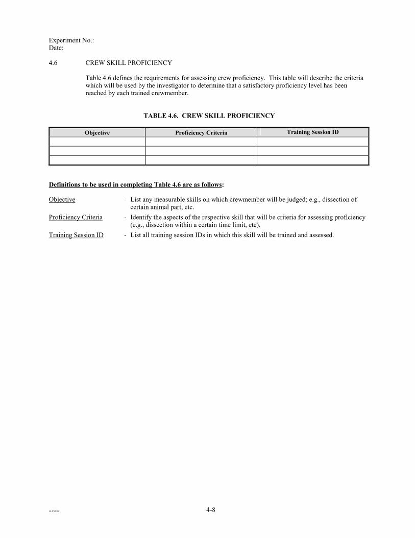
Experiment No.: Date:
LS-XXXXX 4-8
4.6 CREW SKILL PROFICIENCY Table 4.6 defines the requirements for assessing crew proficiency. This table will describe the criteria which will be used by the investigator to determine that a satisfactory proficiency level has been reached by each trained crewmember.
TABLE 4.6. CREW SKILL PROFICIENCY Objective Proficiency Criteria Training Session ID
Definitions to be used in completing Table 4.6 are as follows: Objective - List any measurable skills on which crewmember will be judged; e.g., dissection of
certain animal part, etc. Proficiency Criteria - Identify the aspects of the respective skill that will be criteria for assessing proficiency
(e.g., dissection within a certain time limit, etc). Training Session ID - List all training session IDs in which this skill will be trained and assessed.

Experiment No.: Date:
LS-XXXXX 5-1
5.0 EXPERIMENT FLIGHT SYSTEM REQUIREMENTS
5.1 EXPERIMENT SYSTEM FUNCTIONAL REQUIREMENTS
Table 5.1 defines the functional requirements for the experiment hardware system. The information provided in this table should describe, in sufficient detail, how the experiment system works and how it interfaces with the crew and the vehicle it will be used on. The information in this table will be used as a basis for developing a certification and verification acceptance test plan for the hardware system.
TABLE 5.1. EXPERIMENT SYSTEM FUNCTIONAL REQUIREMENTS
Scientific �� �� ��
Mechanical �� �� ��
Electrical �� �� ��
Interface �� �� ��
Command and Data Handling �� �� ��
Scientific - List the specific operating requirements that must be met in order to achieve the
stated scientific goals. Indicate the types and frequency of measurements that must be made by the experiment system including accuracy, range and sampling frequency. Also, list any requirements necessary to give flight crew or ground personnel feedback on operating status of the hardware.
Mechanical - List whether the experiment system is rack-mounted, stowed, or deployed during in-flight experiment operations. Also, describe how it is restrained if it is to be deployed (i.e., tethers, clamps, Velcro, etc.). Any envelope requirements, especially for systems with various operating /volumetric configurations, should also be noted. Also, note whether the system is crew, increment, or module specific.
Electrical - List how the experiment system will be powered (battery/station/shuttle) on-orbit. If station or shuttle power is required, indicate voltage and current requirements (i.e., 28 Vdc 3A).
Interface - Indicate if the experiment system will interface with existing hardware (workstation, laptop, seat tracks, etc.) and describe the interface (power, data, mechanical, etc). Also, indicate how the system will interface with the crew (i.e., keyboard and display, worn by the crew, etc.)
Command and Data Handling
- List the data storage requirements indicating the type of media used for storage (i.e., flash memory, hard drive, volatile memory, etc.). Indicate data size per collection session and indicate the total number of sessions planned. Indicate if the data is to be downloaded from the experiment system to another storage medium (i.e., PC or Workstation) and if it is to be downlinked to the ground. Indicate if the hardware is to be controlled by the crew only, if ground commanding will be required, or if a combination of both will be utilized.

Experiment No.: Date:
LS-XXXXX 5-2
5.2 EXPERIMENT SYSTEM REQUIREMENTS DOCUMENTS Fill in the table below with any existing hardware and software requirements documentation. NO PI INPUT IS REQUIRED FOR THIS TABLE. This table should include, but is not limited to, the following documentation: HRD, SRD, Interface Control Document (ICD), Interface Design Document (IDD), Functional Requirements Document (FRD), Sustaining Engineering Plan, Hardware User's Guide, Version Description Document (VDD), etc.
TABLE 5.2. EXPERIMENT SYSTEM REQUIREMENTS DOCUMENTS
Hardware Document No. Document Title Comments

Experiment No.: Date:
LS-XXXXX 6-1
6.0 EXPERIMENT HARDWARE
6.1 EXPERIMENT FLIGHT HARDWARE
In Table 6.1., the EST shall list all of the flight hardware (incl. EUE, HRF, shared hardware (h/w), etc.) that will be used at any time during the in-flight portion of the experiment.
TABLE 6.1. EXPERIMENT FLIGHT HARDWARE LIST
Hardware Name Part No. Qty. Dimensions (cm) L W H D
Mass(kg)
Volume Each (cm3)
Volume Total (cm3)
VolumeMLE
Stowed/Rack Mounted/
MD Locker Replacement
(S/R/MD)
Launch Location
Landing Location
Provided By
Definitions to be used in completing Table 6.1 are as follows:
Hardware Name - Provide Hardware Name (shall be provided by the investigator, and should be the same as that listed in Table 3.2-X). Part No. - List Part Number (should be provided by the investigator for Investigator-provided hardware, but will be provided by NASA for all
other hardware). Qty - Provide the quantity of each hardware item required in-flight. Dimensions - Provide dimensions of item using either length by width by height or height by diameter. Mass - Provide the mass of each item. Volume Each - Enter product of dimensions. Volume Total - Provide volume of total quantity of listed item Volume MLE - Use 57,000 cc = 1 Middeck Locker Equivalent (MLE). No PI input is required. Stowed/Rack Mounted/ MD Locker Replacement
- Identify whether item is rack mounted (R), stowed (S), or is a middeck locker replacement (MD).
Launch Location - Using the options below, list all the locations the hardware item can be launched in. Landing Location - Using the options below, list all the locations the hardware item can be returned in.
Location Options: (M) - Middeck (MP) - MPLM (SP) - Spacehab (S) - Soyuz (P) - Progress (NP) - No preference (HOB) - Hardware Onboard
Provided By - Identify the provider of the listed hardware item (PI, NASA, or IP). If NASA is providing the hardware, distinguish between LSE (Laboratory Support Equipment) and SSE (Station Support Equipment).

Experiment No.: Date:
LS-XXXXX 6-2
6.2 BASELINE DATA COLLECTION HARDWARE Table 6.2 will determine the total quantity of BDC hardware required to support ground-based data collection. For each BDC hardware item, list all locations where that hardware item will be required as well as the projected days of use. Based on where and when the hardware item is needed for either pre- or post flight BDC collection, as well as the quantity for each session, the total BDC hardware quantity required for experiment development will be determined.
TABLE 6.2. BASELINE DATA COLLECTION HARDWARE
Location and Dates for Pre and Postflight Activities
JSC KSC Dryden Russia Hardware Item Session ID(s) Total Qty.
Provided By
Schedule Days Qty. Schedule
Days Qty. Schedule Days Qty. Schedule
Days Qty.
Instructions for the table entries are provided below: Hardware Item - List each hardware item needed for ground-based BDC. Session ID(s) - List each ground experiment session ID (from Section 3.1) associated with the hardware item. Total Quantity - Provide an estimate of total quantity based on the dates, locations, and number of tests the BDC hardware is required. Provided by - The organization responsible for providing the hardware (i.e., NASA, PI, IP, etc). Location and Dates for Pre and Postflight Activities
- Indicate the timeframe (L- x, R+ x) when the BDC hardware item will be utilized and the quantity required at a given location. Note that NASA Dryden Flight Research Center (DFRC) is a backup landing site for the Shuttle, and plans should be made to support postflight BDC at both KSC and DFRC. Russia is also an alternate site in the event of a planned Soyuz landing.

Experiment No.: Date:
LS-XXXXX 6-3
6.3 EXPERIMENT UNIQUE EQUIPMENT SYSTEM DEVELOPMENT SUMMARY Table 6.2 lists the types (prototype, mockup, training, etc.) and quantities of experiment unique hardware that are required to support experiment ground and flight operations. Ground operations include procedures development, crew training, and BDC. The ERR version of this table, at a minimum, should include quantities for each type of hardware needed for support and indicate who will develop the hardware. The PDR version should include the information from the ERR version with the addition of any defined hardware names and part numbers. The CDR version of this table should be complete with all applicable fields filled out.
TABLE 6.3. EUE SYSTEM DEVELOPMENT SUMMARY LIST
Hardware Name Part Number Mockup Prototype Training Qualification Flight Flight Backup Total Developed
By
Instructions for the table entries are provided below: Hardware Name - Provide a name for each piece of the EUE system that is to be developed. Part Number - Provide a part number for each piece of EUE system that is to be developed. Mockup - Provide the number of mockup units to be fabricated. A mockup is an uncontrolled non-functional model that will be used as
a volumetric representation of the flight, qualification, and training units. Prototype - Provide the number of prototype units to be fabricated. A prototype is an uncontrolled functional model that will be used as
the basis for designing the flight, qualification, and training units. Training - Provide the number of training units to be fabricated. A training unit is generally uncontrolled and should be of sufficient
fidelity to be a suitable representation of physical design (i.e., same dimensions, mass, volume) and functionally equivalent to the flight and qualification units.
Qualification - Provide the number of qualification units to be fabricated. A qualification unit is generally designated as Class II and is manufactured with the same materials and processes that are used to manufacture the flight hardware. Qualification hardware will be subjected to qualification testing to ensure the reliability of the overall design.
Flight - Provide the number of flight units to be fabricated. A flight unit is designated as Class I and is intended to be flown and operated in space.
Flight Backup - Provide the number of flight backup units to be fabricated. A flight backup unit is a flight unit (Class I) that is intended to replace the primary flight unit in the event of an anomaly in the primary flight unit.
Total - Provide the total number of units that will be developed to support the experiment. Developed By - Enter the provider responsible for the development of the unit (i.e., NASA, PI, ESA, etc.).

Experiment No.: Date:
LS-XXXXX 6-4
6.4 MISSION RESOURCE REQUIREMENTS
This table documents the overall mission resources required for performance of the flight experiment. This experiment-specific information will be used to determine the overall required resources for the missions/increments to which the experiment has been assigned. Table 6.4 contains a list of important mission resources that must be documented for each experiment. These resources should be documented at each experiment review and it is expected that data entered at ERR will be refined through PDR and CDR as the design of the experiment is finalized. Calculations for this table should be based on 180-day mission duration and all values should be expressed per subject per mission unless otherwise specified in the notes section.
TABLE 6.4. MISSION RESOURCE REQUIREMENTS
Mission Resource (units) ERR PDR CDR Mass (kg) Max. Power (kW) Energy (kWh) In-flight Crewtime (M-hr)
Per subject Per operator
Pre-flight Training Crewtime (M-hr) In-flight Training Crewtime (M-hr) Pre-flight BDC Crewtime (M-hr) Post-flight BDC Crewtime (M-hr) Rack Space (Panel Units): On-orbit Stowage Space (cm3) On-orbit Stowage Space (MLE) Ascent Stowage (cm3/mission) Descent Stowage (cm3/mission) Cooling (kg/hr):
Cabin Air Rack Avionics Air
Trash Volume (cm3/subj./mission) Dry Biohazard Wet Radioactive
NOTES:

Experiment No.: Date:
LS-XXXXX 7-1
7.0 EXPERIMENT SOFTWARE The purpose of this section is to determine the need for software for the in-flight portion of the experiment. If such software is required, certain top-level information is required. This section will provide guidance and direction to the software developer. The software developer may be the PI, NASA and/or its support contractors, or an IP.
7.1 EXPERIMENT SOFTWARE INFORMATION
TABLE 7.1. EXPERIMENT SOFTWARE INFORMATION
Software required at NASA facilities? (Check all that apply)
In-flight
BDC
Data Analysis
S/W installed on wkstn/laptop? (Y/N) Embedded in h/w?
(Y/N)
Displays? (Y/N)
Has software flown before? (Y/N) Specify flights:
COTS? (Y/N)
Type of Software License required? (Concurrent, Individual, No Cost)
Software license provided by? (Indicate number of copies to be provided)
PI NASA International Partner
Government Furnished Software? (Y/N)
Software development or modification required? (Y/N)
Developed by? (check all that apply) PI NASA International Partner
Comments, Assumptions:

Experiment No.: Date:
LS-XXXXX 7-2
Definitions to be used in completing Table 7.1 are as follows: Software required at NASA facilities
- Identify whether software is needed in-flight to support the experiment, to support BDC at NASA facilities, and/or support data analysis at NASA and Russian support facilities. NASA facilities include JSC, KSC, Dryden, etc.
S/W installed on wkstn/ laptop
- Includes Shuttle PGSC, ISS Space Station Computer (SSC) or Portable Computer System (PCS), and HRF PC, workstation, or other HRF provided general purpose computers or EXpedite the PRocessing of Experiments to Space Station (EXPRESS) Rack laptop.
Embedded in h/w - Software or firmware that is installed on experiment unique hardware or facility provided hardware.
Displays - User interfaces including graphical user interfaces and h/w front panel displays (Light Emitting Diodes (LEDs), Liquid Crystal Diodes (LCDs))
Software flown before - If the software has flown on a previous mission and will not be modified for the current experiment, choose “Y” and list the previous flights. If the software has flown and will be modified to support this experiment, choose “N.”
Commercial Off-the-Shelf (COTS) software
- COTS software is defined as any software that is sold or traded to the general public in the course of normal business operations and is used “as is.”
Type of Software License required
- All COTS software has some type of license agreement. Please indicate if the software has a “No Cost” (software is distributed for free), “Concurrent” (Need one license for each user), or “Individual” (License required for every installation site regardless of the number of users) license agreement.
Software license provided by
- If the software license must be purchased, how many licenses will be provided by the PI, NASA, or IP? For software to be installed on the HRF Workstation and HRF PC, the integrated software load is distributed to over 40 computer platforms. As a result, at least 40 copies of individually licensed software must be procured.
Government Furnished Software (GFS)
- Includes any software previously developed by the US Government that is certified for use in space
Software development or modification required
- Includes modified COTS software, modified GFS, updates to an existing application, or a completely new application.
Developed by - Identify the provider of listed software item (PI, NASA, or IP) Comments, Assumptions - If required and known, list any operating systems, platforms, or specific software
versions.

Experiment No.: Date:
LS-XXXXX 7-3
7.2 EXPERIMENT FLIGHT SOFTWARE INSTALLATION PLATFORM REQUIREMENTS The purpose of Table 7.2 is to define the installation platform requirements for the experiment software required for in-flight activities. For experiments being performed on ISS, there are several computer system options available. The two primary options are the computer systems the HRF provides for individual experiment use: the HRF Workstation and the HRF PC. Both computers will support general experiment use and are capable of accepting EUSW or standard COTS applications for specific experiment needs. Information on these computers, their design, capabilities, specifications, and system upgrades, may be found in the HRF Workstation Interface Definition Document (IDD) (LS-71042-4), the Rack 2 HRF Workstation Interface Definition Document (IDD) (LS-71042-14-4), and the Portable Computer IDD (LS-71046-1). NASA also provides the ISS SSC platform and the Orbiter Payload and General Support Computer (PGSC) platform that can be used for experiments in certain circumstances. Use of SSC resources must be negotiated with the Station Portable Onboard Computer Control Board (S-POCCB) prior to software development and integration. Use of PGSC resources must be negotiated with the Portable Onboard Computer Control Board (POCCB) prior to software development and integration. Information on these computers, their design, capabilities, specifications, and system upgrades, may be found in the Operations Local Area Network Interface Definition Document (IDD) (JSC 36641) and the Shuttle/Payload Interface Definition Document for the Payload and General Support Computer (NSTS-21000-IDD-760XD)
TABLE 7.2. SOFTWARE INSTALLATION PLATFORM REQUIREMENTS
Installation Platform
Application Name
HR
F R
ack
1
WS
HR
F R
ack
2
WS
HR
F R
ack
1
PC
HR
F R
ack
2
PC
ISS
SSC
Shut
tle
PGSC
EX
PRE
SS
Rac
k L
apto
p
Constraints
Instructions for the table entries are provided below: Application Name - Enter the names of specific applications required for in-flight activities. These
applications can be COTS, GFS, or custom-built. Installation Platform - Check the appropriate column for each platform on which the application is required
to be installed. Constraints - List any constraints concerning the installation of the application to a specific
platform. These may include specific installation instructions and/or hardware that are required to successfully install the software.

Experiment No.: Date:
LS-XXXXX 8-1
8.0 JSC, KSC GROUND PROCESSING This section defines the experiment flight hardware requirements for JSC and KSC ground processing support to assure that the experiment system (1) performs properly and meets its science objectives as part of an integrated payload and (2) is properly integrated into the launch configuration at KSC. This section also defines requirements for proper removal of experiment system hardware and any experiment samples after the return of the landing Orbiter spacecraft.
8.1 JSC GROUND PROCESSING
TABLE 8.1. JSC GROUND PROCESSING REQUIREMENTS
Yes/No If YES, any additional comments or requirements may be documented below Additional Floor Space Special Power Special Water and/or Air Special Flight Hardware Shipping and Cleaning
Instructions for the table entries are provided below: Additional Floor Space - Indicate whether additional floor space at JSC is required and if so, fully define the reasons why in the comments column. Special Power - Indicate the experiment has special power requirements for ground processing of experiment hardware and/or returning experiment
samples. 120 and 28 Vdc power will be available either at a bench setting or from a flight-like station or HRF rack. For battery-powered items, a battery recharger will be made available. Although no AC power will be available on the ISS, the following types of 60 Hz facility power are also available: 120 VAC 1 phase 20 amps 208 VAC 3 phase 30 amps 480 VAC 1 phase 30 amps
Special Water and/or Air - Indicate whether the experiment has special water and/or air requirements for ground processing of experiment hardware and/or returning experiment samples. Most JSC work areas have facility air available at approximately 80 psig and standard water and drains. It should be noted that the facility air is not necessarily cleanliness-controlled.
Special Flight Hardware Shipping and Cleaning
- Indicate whether the experiment has special shipping or cleanliness requirements for ground processing of experiment hardware for shipment to KSC or PI facilities. Standard flight hardware that is not a late load or middeck stowed item is prepared for shipment to KSC or PI facilities by cleaning the items to a visibly clean level using a Freon TF (trichlorotrifluoroethane, technical), and then wrapped in static-free plastic. Shipment is provided by air, van, or airfreight.

Experiment No.: Date:
LS-XXXXX 8-2
8.2 KSC PROCESSING The KSC ground processing for life sciences experiments consists of the integration, checkout, launch, and deintegration of the experiments within the Multi-Purpose Logistics Module (MPLM) and/or the Orbiter middeck. Most of the testing and integration activities at KSC must be executed and coordinated with and through the KSC management system. This is especially true after hardware has been released to KSC for integration. The HRF Payload Project team has prime responsibility for hardware/science payload assembly, test, and servicing while processing through KSC. Payload and Orbiter integrated activities and KSC-provided services identified herein will be the responsibility of KSC. KSC is delegated by the ISS Payloads Office to provide the institutional capability at KSC for processing payloads. Processing includes offline support; physical integration and deintegration; and checkout of payload interfaces to high fidelity ISS and Orbiter simulated interfaces, as well as actual Orbiter interfaces. Payload processing activities extend from simulation(s), through preflight, in-flight, and postflight, to prelaunch and post-landing phases, including supporting late access to the MPLM and to the Orbiter middeck and payload bay, as well as early access to the MPLM and to the Orbiter middeck. Further details of these activities shall be obtained through the EST.
8.2.1 Support Requirements In Table 8.2 the description of experiment launch site processing operations and support activities will be documented. Information for this table will fall into one of the sixteen categories listed below. Further information can be obtained from the EST. • Offline Processing Area and Electrical Power Requirements - if there is a need for an offline processing area with any electrical power
requirements, enter OFF in the category column. This category will include such areas as photo dark rooms, cold rooms, surgery rooms, animal housing, the Orbital environmental simulator, and experiment test areas, etc. Information should include specifics such as: floor area, minimum door dimensions and ceiling heights, sinks, facility air/vacuum, network connections, crane requirements, and hook heights. Any experiment unique or unusual facility environmental requirements should be specified, such as: cleanliness levels, temperatures, humidity, lighting, and unique and/or critical electrical power configurations/requirements.
• On Line Processing Area and Electrical Power Requirements - if there is a need for a processing area after turnover to KSC with any electrical power requirements, enter ONL in the category column. Requirements and specifications for this category should include information at a level comparable to that above, and may be related to post test refurbishment, health checks, etc.
• User Room Area and Electrical Power Support - if there is a need for User Room area and electrical power requirements exist, place USP in the category column of and items provided by either KSC or the HRF Payload Project team for which User Room area and/or electrical power is required.
• Flight Hardware, GSE and Container Storage - if there is a need for Flight Hardware, GSE, or Container storage support, place STO in the category column and the detailed technical information necessary to fully describe the requested support should be supplied. Examples: State the physical dimensions and quantity of items to be stored; advise whether the items can be stacked with other items for purposes of storage; describe how frequently access to the item will be required (i.e., daily/weekly/monthly), and at which points during the ground processing phase; stipulate if long term storage will be required, and for how long; describe any temperature or humidity parameters which must not be exceeded for safe storage of the item; specify minimum cleanliness level required for safe storage of the item

Experiment No.: Date:
LS-XXXXX 8-3
• KSC Administrative Support - if there is a need for Administrative Support, enter ADM in the category column. These requirements include transient office areas and furniture, telephone for voice, fax and modem and computer network access, etc. Examples: Furniture and office equipment (area required in square feet, number of people, quantity of desks, chairs, tables, etc.); number of telephone handsets, fax lines, voice lines, etc.
• KSC GSE and Special Test Equipment - if there is a need for KSC GSE and Special Test Equipment support, enter STE in the category column. If there is a preferred outside vendor for the GSE/Test Equipment, please identify them, along with the equipment’s part number. Examples: Forklifts, cranes, dollies, carts, hydra sets, Leak detectors, workbenches, power supplies, MultiMate’s, vacuum GSE, Operational Intercommunication System, Digital (OIS-D) Headsets, accelerometers, temperature and humidity recorders, toxic vapor detectors, Helium (He) detectors, particle counters, plant growth chambers, exhaust hoods, laminar flow benches, etc. Additionally, indicate if there are times when GSE/Test Equipment will not be actively utilized, during which time others may use the hardware. If such times do exist, please indicate the critical time period(s) during which the Payload Developer (PD) will be actively using the equipment (i.e., the times during which it cannot be shared).
• Reusable and Expendable Supplies - if there is a need for Special Laboratory Areas and Capabilities support, enter EXP in the category column. For a particular requirement, the detailed technical information necessary to fully describe the requested support should be supplied. If there is a preferred outside vendor for the GSE/Test Equipment, please identify them, along with the equipment’s part number. Also indicate if equivalent substitutes are acceptable.
• Fluid Resources - if there is a need for Fluid resources, enter FLU in the category column. For a particular requirement, the detailed technical information necessary to fully describe the requested support should be supplied. Examples: GN2, He, Alcohol, Air, etc. Specify minimum, nominal, and maximum pressures and flow rates for each fluid, as well as the quantity of each required. Refer to SSP 30573, Space Station Program Fluid Procurement and Use Control Specification, for additional information concerning fluid specifications.
• Chemicals - if there is a need for Chemicals Support, enter CHE in the category column. Include all chemical supplies to be used at KSC; those requested from KSC, chemicals shipped to KSC, and chemicals produced by processes during processing operations. Material Safety Data Sheet (MSDS) and Process Waste Questionnaires (PWQs) must be submitted prior to first use for all chemicals to be used at KSC. For a particular requirement, the detailed technical information necessary to fully describe the requested support should be supplied. If there is a preferred outside vendor for the GSE/Test Equipment, identify them along with the equipment’s part number. Also indicate if equivalent substitutes are acceptable.
• Payload Data Transmission and Recording - if there is a need for Payload Data Transmission and Recording support, enter DAT in the category column. For a particular requirement, the detailed technical information necessary to fully describe the requested support should be supplied. Examples: List the type of data which is to be transmitted/recorded (such as OIS-D, Data, TV/Video signals, etc.). If recording is required, specify the desired recording medium (120 min Video Home System (VHS) Video Tape, 1.44 Meg 3 ½ floppy discs, C-60 audio tape, etc.). Specify the facilities or locations from which the signals will originate and to which they will be transmitted.
• Transportation/Shipping (T/S) - if there is a need for Transportation support, enter T/S in the category column of Table 9.2 and requirements. Include ground transportation of HRF Payload Project team experiment samples and equipment between payload facilities at the launch site and at the Shuttle Landing Facility (SLF) and DFRC landing facilities. Describe the type of experiment samples or equipment for which transportation assistance is required. Describe all services and/or considerations which are pertinent to the transportation of the Item. HRF will be responsible for coordinating and providing inputs per all special, sensitive, or unique T/S activities with KSC support personnel. For a particular requirement, the detailed technical information necessary to fully describe the requested support should be supplied. Examples: transportation assistance required (crane, forklifts, transport dolly, etc.); special handling constraints/techniques; environmental considerations

Experiment No.: Date:
LS-XXXXX 8-4
(temperature, cleanliness, humidity, etc.). Indicate whether the requirement involves shipping of animals, plants, or other perishable cargo. List the facilities from and to which the item should be transported.
• Technical Support Services (TSS) - if there is a need for Technical Support Services, place TSS in the category column. Specify the type of technical service required, such as: technician support (electrical, mechanical, quality inspection); special services (precision cleaning, decontamination, foam cutting, specimen preparation, sample analysis, leak detection, electromagnetic measurements, machining, optical lab services, long term hardware maintenance, etc.); animal/vertebrate; science; or unique environmental support, such as high cleanliness or low humidity.
• Photographic and Video Support - if there is a need for Photographic and Video Support, place PHO in the category column. Describe the nature of the operation/event to be photographed/recorded (such as major lift, plant growth, etc.). Describe in detail the type and specifications of desired recording medium (such as 35 mm print, Hi-Quality videotape, 800 x 600 dpi digital photos, etc.), and the estimated quantity of each type of photo/video support requested (such as number of prints, contact sheets, duplicate negatives, etc.).
• Communications - if there is a need for Communications Support, place COM in the category column. Examples: Estimate the quantity of headsets, etc., required.
• Personnel Access and Training Requirements - if there is a need for Personnel Access and Training support, place ACC in the category column and list the name of each person requiring access to KSC facilities, Company or organization affiliation, national citizenship, area of access requested (e.g., KSC Industrial Area, Space Station Processing Facility (SSPF) Clean Work Area, Orbiter Processing Facility (OPF), Pad, Animal Care Section, etc.). If unescorted access into controlled work areas is required, such as the SSPF Clean Work Area, a current certification in the NASA Personal Responsibility Program (PRP) is required.
• Hazardous Disposal, Storage, and Handling - if there is a need for hazardous disposal, storage, or handling, place HAZ in the category column and identify information necessary to accommodate hazardous products handling, storage and disposal by the HRF Payload Project team during KSC processing or a KSC activity in support of the HRF Payload Project team. For a particular requirement, the detailed technical information necessary to fully describe the requested support should be supplied. Where possible, estimate the quantity of each requirement for which disposal, storage, or handling is needed.
• Other - Identify any other support required that is not detailed in the categories above.

Experiment No.: Date:
LS-XXXXX 8-5
TABLE 8.2. LAUNCH/LANDING SITE REQUIREMENTS
Cat. Requirement Specifications Phase Comments
Definitions to be used in completing Table 8.2 are as follows: Category - From the descriptions above, and the acronyms below, assign a category to the launch/landing site requirements:
ACC Personnel Access and Training Requirements ADM KSC Administrative Support CHE Chemicals COM Communications DAT Payload Data Transmission and Recording EXP Reusable and Expendable Supplies FLU Fluid Resources HAZ Hazardous Disposal, Storage, and Handling OFF Offline Processing Area and Electrical Power Requirements ONL On Line Processing Area and Electrical Power Requirements OTH Other Requirements PHO Photographic and Video Support STO Flight Hardware, GSE and Container Storage STE KSC GSE and Special Test Equipment T/S Transportation/Shipping TSS Technical Support Services USP User Room Area and Electrical Power Support
Requirement - Identify the type of requirement needed, such as floor space, a laboratory, expendable supplies, special test equipment, etc.
Specifications - Indicate, in a short description, the actual support requirement. For a particular requirement, the detailed technical information necessary to fully describe the requested support should be supplied, i.e., temperature, relative humidity, and cleanliness parameters required for safe storage or transportation of a payload; floor area needed; crane requirements (i.e., 10-ton Monorail); facility physical dimensions; electrical power requirements (120 VAC 3-phase, 15-A, 60 Hz).
Phase - Indicate the time(s) using Launch (L)+/- or Return (R)+ during the payload processing flow when a particular support is required, from beginning to end of the support, measured in days. Indicate the duration for each requirement. Ex: Preflight (L-X to L-Y); In-flight (L+X to L+Y); Postflight (R+/-X to R+Y).
Comments - Indicate any information of importance that is not called out in any of the other requested fields.
Experiment No.: Date:
LS-XXXXX 9-1
9.0 DATA REQUIREMENTS AND MANAGEMENT This section shall describe the data products required to support the experiment. This section provides tables for the investigator to specify which products and services are required by the experiment. A separate document, the JSC TSC Capabilities Document, that lists the data products and services available, can be delivered to the investigator prior to filling out this section. Input to tables in this section will provide agenda items for meetings with NASA personnel to obtain detailed information for mission and integrated payload data requirements documents (DRDs). If an experiment requires TSC or remote site support, the detailed requirements will be compiled in a DRD prepared by NASA. The focal point for all operations and in-flight data activities will be the JSC TSC. The JSC TSC will receive and process both payload science and facility data and transmit experiment specific data to remote investigators through the Internet and a Virtual Private Network (VPN). PIs can use the TSC during experiment operations and take advantage of TSC consoles and services or choose to operate remotely from their home site(s), interfacing with the TSC as required to support each function. To do so, the PI must apply for a VPN account via the Web site http://tsc.jsc.nasa.gov, by choosing the “Request for a New Account” option. Accounts are generally needed no earlier than I-6 months. Once the account has been approved, passwords must be renewed to keep the account active. List your requirement for a VPN account in Table 9.4. NOTE: The investigator should be aware that, at times during the mission, there may be little or no communications link between the spacecraft
and the ground. If the experiment must be performed so that ground teams can see realtime video and/or data (Ku band link) and/or hear audio (S band link), that requirement must be defined as mandatory under the timelining constraints of the appropriate table in Section 3.2.

Experiment No.: Date:
LS-XXXXX 9-2
9.1 DATA MANAGEMENT REQUIREMENTS In Tables 9.1.1 and 9.1.2, the investigator shall identify information regarding data management requirements at the JSC TSC or at a remote site (investigator’s home location). If the investigator chooses to support mission activities from a remote location, minimal computer hardware, browser, and operating system requirements will be recommended for optimal performance. In some cases, more than one computer may be needed to view both real-time data and voice loops. Voice communication will be implemented using Internet Voice Distribution System (IVoDS) software that will be provided to the investigator. Remote site system requirements are available at http://tsc.jsc.nasa.gov/tsc_requirements.htm.
9.1.1 Telescience Support Center Data Management Requirements In Table 9.1.1, identify the location from which the investigator will require support (JSC TSC or remote). If remote site support is chosen, the investigator will be required to fill out Table 9.1.2
TABLE 9.1.1. TSC DATA MANAGEMENT REQUIREMENTS
Experiment team location for In-flight monitoring:
JSC TSC (Y/N) Remote site (PI, Co-I or team member facility). Please
identify location, if known.
JSC TSC based experiment team requirements Estimated # of people in TSC Unique GSE brought to TSC Hardware Item Description Interface w/TSC Equipment Display Requirements (Y/N)
Strip Chart Requirement (Y/N) Deliverable Data Products

Experiment No.: Date:
LS-XXXXX 9-3
Definitions to be used in completing Table 9.1.1 are as follows: JSC TSC - Indicate “Y” if the investigator will monitor in-flight activities from the JSC TSC. Indicate “N” if the investigator will not monitor
in-flight activities from the JSC TSC. Remote site location - Identify the address of the remote location. Estimated # of people in TSC
- Identify the number of console workstation positions required and the approximate number of people that may be on console at any one time. Each workstation will include access to ISS and Shuttle data displays, video monitoring, and voice loops, and experiment data displays
Unique GSE brought to the TSC
- Identify any GSE (laptops, etc.) the investigator will bring to the TSC that requires power or data interfaces (internet).
Display Requirements - The investigator shall indicate whether there are ground displays or strip chart recorder needed in the TSC to view real-time telemetry data.
Strip Chart Requirement - Indicate whether real-time or NRT downlink video will be needed to support your science from the TSC. Privatized video (intended for investigator only) will only be available in the TSC real-time.
Deliverable Data Products
- Identify all data products expected real-time or NRT. Data includes downlinked data files from a laptop, workstation, or other device on orbit, real-time displayed (processed) data, test or verification data, or any other data (station pressure, temperature, vehicle position, etc.) relevant to the experiment.
In Table 9.1.2 identify the requirements necessary to successfully support remote site support for investigations on Shuttle or ISS.
TABLE 9.1.2. REMOTE SITE DATA MANAGEMENT REQUIREMENTS
Remote site based experiment team requirements Voice Loop (Y/N) Monitor Two Way
Video (Y/N) Data (Y/N)
Definitions to be used in completing Table 9.1.2 are as follows: Voice loop - Identify whether voice loops will be needed to support your science from the remote site. If voice loops are indicated, indicate
Monitor only or Two-Way communication by placing and “X” in the appropriate block, otherwise leave blank. Video - Indicate whether real-time or NRT downlink video will be needed to support your science from the remote site. Real-time video
will require access to NASA Select TV and may only be available in the JSC TSC. Privatized video (intended for investigator only) will only be available in the JSC TSC real-time.
Display Requirements - Indicate whether there are ground displays needed to view real-time telemetry data.

Experiment No.: Date:
LS-XXXXX 9-4
9.2 FILE UPLINK/DOWNLINK AND COMMANDING REQUIREMENTS Onboard data files can be downlinked to the ground through the HRF Common Software on the HRF PC (laptop) and Workstation computers located in either HRF Rack. Files from other onboard station and Shuttle computers may be downlinked using other methods not controlled by HRF. Files are typically downlinked NRT and Ku-band antenna signal acquisition and bandwidth are constraining factors. Table 9.2 identifies file uplink/downlink and commanding requirements.
TABLE 9.2. FILE UPLINK/DOWNLINK AND COMMANDING REQUIREMENTS
Command Requirements
Estimated file size(s) File Downlink Number of files created for each on-orbit session
Estimated file size(s) File Uplink Number of files created for each on-orbit session
Command Requirements - Identify commanding requirements if your experiment hardware or software will allow command activation, deactivation, or control.
File Downlink - Provide an estimate of a typical file size expected and how many files will be generated per experiment session. File Uplink - Provide an estimate of the file size and quantity for file uplink and transfer capabilities.

Experiment No.: Date:
LS-XXXXX 9-5
9.3 ARCHIVED DATA REQUIREMENTS All onboard flight media are returned to the LSDA after landing, copied and the data archived. Multiple copies are kept by LSDA and one compact disc (CD) copy is forwarded to the PI via the ESM. Once the PI receives the data, it is imperative that the data be promptly reviewed, so that NASA can completely erase the flight media and recycle it for use on later flights. Original logbooks are also returned to LSDA and scanned electronically; originals are returned to the investigator, who may also request an electronic copy. Telemetered experiment data are received by the TSC, distributed NRT to the PI via the TSC Web site, and archived in the LSDA. The format and media of the data product can also be altered from that returned postflight to one more advantageous for analysis by the investigator. Table 9.3 describes the in-flight data information required by LSDA.
TABLE 9.3. FLIGHT MEDIA REQUIREMENTS
Flight Media/Log Books being used in-flight
Flight Media Capacity Telemetered Data Expected Telescience Support Center (TSC) VPN account needed? (Y/N)
Definitions applicable to experiment data management at remote sites are as follows: Flight Media/Log Books being used in-flight
- Identify the type of media returned after flight (Personal Computer Memory Card International Association (PCMCIA) cards, floppy disk, hard drive, etc.).
Flight Media Capacity - List details of flight media expected capacity and fullest capacity Telemetered Data Expected
- List the parameters to be captured
TSC VPN account needed
- Indicate whether a VPN account is desired. Access to a VPN will provide the capability to view experiment data files and gives access to download files.

Experiment No.: Date:
LS-XXXXX 9-6
9.3.1 Preflight and Postflight Baseline Data Collection Data In Table 9.3.1, describe the data product, issues, and the data formats involved.
TABLE 9.3.1. PRE AND POSTFLIGHT DATA REQUIREMENTS
“Raw” data products generated in BDC session, including data formats
Location of data collection Plan for data transfer to LSDA Proprietary data issues? (Y/N) If “Y” explain. Data encryption issues? (Y/N) Data storage issues? (Y/N) If “Y” explain. Other BDC data issues? (Y/N) If “Y” explain.
Definitions applicable to any other experiment data management concerns are as follows: “Raw” data products generated in BDC session, including data formats
- List data formats expected. Standard format examples are Excel, Word, and JPEG/TIFF/GIF images. Data can be in the following forms: spreadsheet, images, video tapes, analog tapes, and hard copy log books, lab books, others.
Location of data collection
- JSC, PI Lab, etc.
Plan for data transfer to LSDA
- Indicate how you will transfer data to the LSDA (ZIP, JAZ, optical, floppy, CD, hardcopy, File Transfer Protocol (FTP) server, etc.).
Proprietary data issues - Indicate “Y” if there are any proprietary data formulas, etc. and explain what is proprietary. EXAMPLE: Actiwatch software was developed by the investigator and is proprietary; therefore, it cannot be provided to LSDA. Indicate “N” if there are no proprietary data issues.
Data encryption issues - Indicate “Y” if the raw data products are encrypted. Indicate “N” if the raw data is not encrypted. Data storage issues - Indicate “Y” if there are any data storage issues and explain what the issues are (i.e., volume, formats, temperature sensitivity, etc).
Indicate “N” if there are no data storage issues. Other BDC data issues - Indicate “Y” if there are any other BDC data issues and explain what the issues are that need to be addressed by the LSDA in order
to complete archiving tasks. EXAMPLE: PI wants to provide analyses on Optical Disk. Indicate “N” if there are no other BDC data issues.

Experiment No.: Date:
LS-XXXXX 9-7
9.3.2 Investigators Data Analyses All analyzed data are required to be submitted to the LSDA. Some are submitted via the NASA final report, while others are published in journal articles. In addition to the raw data, LSDA requires data in an analyzable form; therefore, data used to generate results found in publications should be submitted.
TABLE 9.3.2. INVESTIGATORS DATA ANALYSES
Data formats of expected analysis Timeframe when analyses are expected to be complete
Definitions applicable to any other experiment data management concerns are as follows: Data formats of expected analysis
- Expected analyses result from pre/in/post data, including data formats. List data formats expected. Data can be in the following forms: spreadsheet, images, video tapes, analog tapes, and hard copy log books, lab books, etc. Standard format examples are Excel, Word, JPEG/TIFF/GIF images.
Timeframe when analyses are expected to be complete
- Indicate an expected timeframe for analysis completion, R+30, R+90, R+180, 1 year, etc.
For data collected on human subjects, only mean pooled (non-attributable) data sets are downloadable from the public web site. LSDA collects individual (attributable) human data, but does not distribute these data via the public web site. The PI needs to identify subjects for LSDA; the JSC CPHS has approved this process. JSC LSDA team members sign non-disclosure statements as specified by the JSC CPHS. Individual human data are kept in a secure Web-based system identical in structure to the public Web site, but the data are not on the Internet-at-large. In the future, if researchers are allowed to utilize this restricted-access Web site, the researcher will have to submit a proposal to the JSC CPHS, and the subject will have to grant permission for use of the data.

Experiment No.: Date:
LS-XXXXX 9-8
9.4 MISCELLANEOUS DATA REQUIREMENTS In Table 9.4, the investigator shall identify any data requirement not covered by the tables in Sections 9.1 through 9.3. During training/BDC at JSC or training/BDC/integration at KSC, performance of the experiment could allow verification of the data flow and also provide science verification data. If data support is required during these activities, identify this requirement. If any of the parameters are different in any of these activities than they would be for an in-flight performance of the experiment, identify those differences. Also, some investigations may require data flow monitoring on the flight to or from the ISS, either as experiment sessions or monitoring of hardware performance. Special arrangements will need to be made for this data flow. If this is a requirement, provide any known information.
TABLE 9.4. MISCELLANEOUS DATA REQUIREMENTS
Training/BDC data support required at JSC (Y/N) If “Y” above: Are the data parameters for the training/ BDC activity at JSC different from in-flight parameters (Y/N)? If “Y” explain.
Training/BDC/Integration data support required at KSC (Y/N)
If “Y” above: Are the data parameters for the training/ BDC/integration activity at KSC different from in-flight parameters (Y/N)? If “Y” explain.
Launch/Landing data flow monitoring (Y/N). If “Y” explain.
Definitions applicable to any other experiment data management concerns are as follows: Training/BDC data support - JSC
- Indicate “Y” if data support pre/post flight training and/or BDC will be required. Explain what the differences are and the rationale for the differences in the row below. Indicate “N” if no data support is required.
Training/BDC/Integration data support - KSC
- Indicate “Y” if data support pre/post flight training and/or BDC and/or integration will be required. Explain what the differences are and the rationale for the differences in the field below. Indicate “N” if no data support is required.
Launch/Landing data flow monitoring
- Indicate “Y” if the experiment or hardware must be monitored during launch or landing. Explain the rationale for monitoring and specify if it is for launch, landing, or both. Indicate “N” if no monitoring is required.

Experiment No.: Date:
LS-XXXXX 10-1
10.0 DOCUMENTATION REQUIREMENTS This section describes the documentation products that the PI is required to deliver in support of this experiment project. In addition to the requirements for filling out the information tables contained within the ED, there are a number of other items of documentation that are required to be delivered in support of this experiment project. The listings in this ED section should not in any way preclude documentation requirements or other deliverables that may be imposed on the PI as a consequence of their contract or an EUE HRD.
TABLE 10.1. DOCUMENTATION REQUIREMENTS
Experiment Phase Deliverable
Definitions to be used in completing Table 10.1 are as follows: Experiment Phase - Indicate the phase of the experiment (i.e., definition, design, or
implementation) in which the documentation will be submitted. Deliverable - Indicate the title of the document to be submitted (i.e., Experiment
Document, System Requirement Document, Procedures, etc.)
10.1 EXPERIMENT MANAGEMENT DOCUMENTATION
10.1.1 Experiment Management Plan The purpose of the Experiment Management Plan (EMP) is to document the organizational relationships within the PI’s team and the management approach that the PI will take for his/her experiment implementation. This plan is a useful tool in establishing the lines of communication and points of contact for the NASA EST. Since this plan helps to define the working relationship between NASA and the PI team, international PIs should consult their appropriate sponsoring agency representative regarding organizational and administrative requirements. Personnel who will carry out the experiment should be identified, along with a description of expected activities during all phases of the program. A graphical illustration of the relationships for managing and conducting the work is very helpful. The illustrations should include an explanation of the internal structure and lines of authority and/or responsibility for the PI's institution. External interfaces and relationships with NASA, support organizations, and associated investigators should also be delineated. The EMP is a definition phase deliverable item and is provided to the ESM. This can be done as a separate document or included with other submittals, such as budget or schedule submittals.
10.1.2 Experiment Activities and Milestones Schedule The ESM/EST shall prepare and maintain two types of schedules showing experiment milestones and activity time spans. One schedule will highlight activities performed during the experiment definition,

Experiment No.: Date:
LS-XXXXX 10-2
design, and implementation phases. Additional schedules will be created for each mission on which the given experiment is manifested. These mission specific schedules will highlight activities that will take place during the experiment’s flight phase and will be developed with the help of the NASA experiment team. Initially NASA will use the Experiment Activities and Milestones Schedule to evaluate the feasibility of developing the experiment on a timetable that is consistent with program objectives and to determine which ISS increment should be targeted for flight. Periodic updates of the schedule are then used to assess the progress of experiment development activities and to re-evaluate compliance with increment and program schedule requirements. The schedule should reflect the major development activities and milestones for the experiment, including (but not limited to) ground supporting studies, PI-provided EUE and EUSW activities, protocol development activities, BDC or other hardware procurements, etc. The schedule should be prepared using Microsoft Project. The Experiment Activities and Milestones Schedule will be continually updated during the course of the experiment development, but should be initially submitted to the ESM during the definition phase.
10.1.3 Progress Reports In order to effectively track the development of the experiment, the NASA ESM will need a periodic progress report from the PI. This requirement can be met through means other than a formal written report, such as monthly teleconferences, frequent regular communications, etc. In some circumstances, however, the generation of a written report may be the most effective way of meeting this requirement (example, a foreign PI under direct experiment development management by his/her sponsoring agency). If the NASA ESM and the PI sponsoring agency representative agree to a written report, it should include separate discussions of science activities and engineering activities (as necessary). Each of these discussions should include the following information: a. A quantitative description of overall progress b. A discussion of the work performed during the past month c. A discussion of the work to be performed during the next monthly reporting period. d. A description of any current problems which may impede performance, and a discussion of
proposed solutions for those problems. In the discussions in the monthly reports the PI should provide a clear picture of where the PI stands with respect to meeting the major milestones of the project (ERR, PDR, CDR, etc.). Any proposed changes or updates to the Experiment Activities and Milestones schedule changes should also be included in the report. This report should be provided to the ESM by the tenth day of each month for the previous month’s work.
10.2 SCIENCE SUPPORT DOCUMENTATION
10.2.1 Human Research Protocol All investigators proposing experiments involving humans shall adhere to the principles governing such research that are set forth in Protection of Human Research Subjects, NMI 7100.8A, which establishes the requirements for the contents of a protocol. A copy of the latest revision of JSC-20483, JSC Institutional Review Board: Guidelines for Investigators Proposing Human Research for Space Flight and Related Investigations, will be provided to the PI. This handbook describes the format that the PI will use for submitting human research protocols. The PI shall submit a draft version of the proposed Life Sciences Research and Training/BDC Protocols at the CDR. The final Protocols will be delivered to NASA either a) at least 60 days prior to

Experiment No.: Date:
LS-XXXXX 10-3
the CDR or b) at least two months prior to the informed consent briefing of the increment on which the experiment has been manifested. Protocols will be submitted to the respective agency CPHS two months prior to the first training session. All action items resulting from CPHS review must be closed prior to the first training session, although authority may be granted to conduct informed consent briefings with the crew. Action item closures should be forwarded to the ESS for submission by the IS to the CPHS. Tests using non-crew subjects also require the investigator to obtain CPHS approval of a human research protocol and will follow a similar process. Protocols will be promoted to the HRMRB for review prior to the first preflight BDC session. Action items resulting from this review will be handled in a manner similar to that of CPHS Action Items. The PI shall update protocol information when requested by NASA. For each protocol submission, one reproducible, signed copy shall be submitted to the ESM. Twenty copies will be made by the ESS for submission to the CPHS by the IS.
10.2.2 Experiment Operating Procedures The PI, with the assistance of the EST, will develop procedures that describe the steps to perform the experiment and explain how to operate the experiment equipment. These procedures will be formatted by NASA and used by the flight crew for experiment training and on-orbit operations. Due to the limited opportunity to train with the crew, these procedures must be desk top validated and complete usability testing for approval prior to the training sessions. This will help insure that a certain level of stability is maintained over the experiment operations and procedures in order to maximize the effectiveness of our extremely limited time with the crew. NASA will combine individual experiment procedures in the User Requirements Collection (URC) database which will consist of integrated flight crew procedures, crew checklists, cue cards, and other materials that will assist the crew in carrying out the planned flight activities. From time to time the PI will be required to assess the adequacy of these materials, and the PI will ultimately provide a certification of flight readiness for the final version of the URC database. In order to accommodate these reviews and to allow for experiment operating procedures and updates shall be submitted 60 days prior to each training exercise that requires such procedures. NASA will supply the format. One reproducible copy shall be submitted to the ESM and another copy to the ESS.
10.2.3 Experiment Manual Depending on the outcome of a training analysis or specific program requirements, the PI may be required to provide a training workbook to be used as a reference by the payload and ground crew. If required, the initial submission of this workbook shall be required no later than 30 days before the first experiment training exercise to allow for review. If required, the exact format for the workbook will be provided to the PI.
10.2.4 Supporting Studies Impact Reports In general, supporting studies are conducted to provide information about some undefined aspect of the experiment concept. The PI must advise the ESM immediately when the results of such studies indicate that there will be a previously unforeseen impact on the experiment project. Any study result that will affect the experiment project cost or schedule; the form, fit, or function of the experiment equipment; the crew time required to perform the experiment; or the feasibility of the present experiment concept, shall be reported. A supporting study impact report should be submitted as soon as the study results indicate that there is an experiment project impact. The report needs to describe the relevant results and define the impact to the experiment project that the results suggest.

Experiment No.: Date:
LS-XXXXX 10-4
If the study results indicate the need for a modification to the flight experiment in an area that is under configuration control, then the impact report shall clearly specify the anticipated change and state the date when a Change Request will be submitted. Changes to baselined requirements require SM3 CCB approval. One copy of each impact report shall be submitted to the ESM.
10.2.5 Final Supporting Study Reports For each authorized supporting study, the PI is required to submit a final report that describes the conduct and the results of that study. Each final report should contain an abstract summarizing the study plus a complete description of the study, including the study objectives, methods, results, conclusions, and recommendations. The report should include all calculations, data, charts, photographs, and drawings necessary to comprehensively explain the results. The report should also discuss any supporting study impact reports (See Section 10.2.4) associated with the study. A copy of all papers and reports pertaining to the study should be included as an appendix to the report. One copy of each report shall be submitted to the ESM. These shall be submitted no later than 60 days after the completion of the study.
10.2.6 Science Verification Report When all elements of the experiment are sufficiently mature, including flight hardware, software and crew procedures, a SVT and appropriate analyses will be performed to verify that the overall experiment system satisfies the scientific objectives stated in Section 2.0 of this ED. As a part of this process, the PI shall prepare and submit a Science Verification Report. Science verification will begin with the conduct of an SVT by JSC personnel. This test will consist of a flight-like sequence of experiment operations which includes ground support and monitoring activities and the collection of experiment data in the same format planned for the collection of actual in-flight experiment data. In some cases, the entire flight protocol may be performed, and in others a representative portion of the experiment may yield enough data for evaluation. The SVT data will then be provided to the PI who shall reduce and analyze the data using the same techniques and methods planned use with actual flight data. When the analyses have been performed, the PI will prepare and submit a Science Verification Report that describes the results of the analyses. The PI will end the report with a statement certifying the adequacy of the experiment system to support the scientific objectives of the experiment. The Science Verification Report is due to NASA no later than 30 days following receipt of the SVT data. Copies shall be addressed to the ESM.
10.3 EXPERIMENT UNIQUE SOFTWARE DOCUMENTATION If EUSW is included in the experiment system and the PI is providing that software, the PI is required to provide an Experiment Software Document according to the document LS-40072, Experiment Software Documentation Guidelines and Requirements.
10.4 SAFETY DOCUMENTATION
10.4.1 Payload Safety Data A detailed safety review will be conducted for the flight experiment and equipment. This safety review is conducted in several stages or phases, and the PI is required to provide certain information for inclusion in the safety data package. (Those PIs who are developing EUE will find additional

Experiment No.: Date:
LS-XXXXX 10-5
safety reporting requirements in their HRDs.) This information shall, at a minimum, include the following items at the appropriate phase: 1. Phase 0
a. Experiment description and operation. b. Inputs to description of safety critical subsystems and their operations.
2. Phase I (Phase 0 and I are usually grouped into a single review.) a. Input for block diagrams, schematics, and/or a description of safety-critical subsystems and
their operations. b. Input for Hazard Reports (JSC form 1230/542B). Radioactive source questionnaire (JSC
form 44), if applicable. c. A list of battery types, their uses, and manufacturer. d. Inputs to Fire Detection and Suppression approach. e. Inputs to on-orbit maintenance safety assessment.
3. Phase II a. Updates to all phase 0/I data. b. Inputs to wire sizing and fusing diagrams. c. Inputs to the list of Shuttle and/or ISS provided critical services. d. Information on test failures, anomalies, and accidents involving qualification or potential
flight hardware. e. Inputs for updated hazard reports and support data including the following:
(1) Radioactive source questionnaire (update), if applicable. (2) List of toxic materials, if applicable.
4. Phase III a. Updates to all Phase II data. b. Inputs to final as-built payload description. c. Results of applicable safety verification tests and analyses. d. A summary and safety assessment of all test failures, anomalies, and accidents. e. Information required to close all action items. f. Assistance with ID of flight safety non-compliances.
10.4.2 Payload Ground Safety Data
In addition to the flight safety review process referenced in Section 10.4.1, there is a ground safety review process which covers activities conducted at KSC. As with the flight safety process, the PI is required to provide certain information for inclusion in the safety data package. (Those PIs who are developing EUE will find additional safety reporting requirements in their HRDs.) The safety analysis data shall consider all experiment hardware and GSE. The hazard analyses shall consider the effect of each hazard on the Orbiter, the launch site facilities, other payloads, and personnel. The Phase 0, I, II, and III Ground safety reviews are usually grouped together unless the flight hardware, processing or GSE are particularly complicated. This information shall, at a minimum, include the following items at the appropriate phase: 1. Phase 0
Experiment/GSE conceptual design established. (1) Provide experiment description and operation. (2) Assist with ID of potential hazards. (3) Input to ground operations scenario.

Experiment No.: Date:
LS-XXXXX 10-6
2. Phase I Experiment/GSE preliminary design established. (1) Updates to all Phase 0 data (2) Provide block diagrams, schematics, and/or a description of safety-critical subsystems and
their operations. (3) Inputs to the ground operations concept for the integration and testing of the experiment at
KSC. (4) Inputs to the preparation of hazard reports (JSC Form 542B). (5) Estimated KSC on-dock arrival date (6) Input to post-flight operations at KSC or alternate landing site.
3. Phase II Experiment/GSE final design established. (1) Help to refine and expand safety analysis, evaluate interfaces, and ground operations
procedures. (2) Update hazard descriptions, causes, and controls. (5) Inputs to update safety-critical subsystems descriptions. (6) Provide a list of technical operating procedures to be used at KSC, with particular attention to
hazardous procedures. 4. Phase III
Experiment/GSE fabrication and testing complete. (1) Updates to all Phase 0, I, II data. (2) Submit results of applicable safety verification tests and analysis. (3) Provide technical operating procedures (provide inputs). (4) Provide a list of safety-related failures or accidents.
10.4.3 Baseline Data Collection Safety Data
Prior to any BDC activities at JSC or KSC, the BDC equipment and operations must be reviewed by the appropriate local safety organization. The BDC safety process at JSC will be conducted in the same manner as a TRR, as referenced in Section 4.3. The safety process for BDC at KSC will be included in the Ground Safety Data Package as described in Section 10.4.2.

DISTRIBUTION LIST FOR
LS-20079-2A NASA/JSC SM3/M. Anderson D. Baumann L. Campbell C. Guidry C. Haven M. Kamman A. Lee C. Maender
S. McCollum LOCKHEED MARTIN C45/C. Williamson S03/Science Payloads Library S03/M. Pickett S03/G. Sandoz S03/J. Valverde S362/TDI Center/Bldg. 36 (5)