experiment manual - thames & kosmos€¦ · small sprocket medium sprocket ... and encourages...
TRANSCRIPT
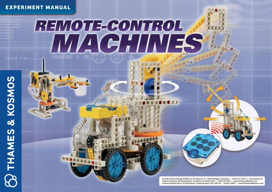
E X PE R I M E NT M A N UA L
Franckh-Kosmos Verlags-GmbH & Co. KG, Pfizerstr. 5-7, 70184 Stuttgart, Germany | +49 (0) 711 2191-0 | www.kosmos.de Thames & Kosmos, 301 Friendship St., Providence, RI, 02903, USA | 1-800-587-2872 | www.thamesandkosmos.com Thames & Kosmos UK LP, 20 Stone Street, Cranbrook, Kent, TN17 3HE , UK | 01580 713000 | www.thamesandkosmos.co.uk

REMOTE-CONTROL MACHINES | Contents and Safety Information
Receiver/Battery Holder
Remote Controller
Insert three AA batteries (1.5 V) into the combination receiver/battery holder. The polarity of the batteries and the markings on the battery compartments should match.
1. Lightly press and slide the lid outward to open it.
2. Insert two AA batteries (1.5 V) and pay attention to the polarity of the batteries and the markings on the compartments.
3. Slide back the lid.
SAFETY INFORMATION
WARNING! Not suitable for children under 3 years. Choking hazard — small parts. WARNING! Only for use by children aged 8 years and older. Instructions for parents or other supervising adults are included and have to be observed. Keep packaging and instructions as they contain important information.
ADVICE TO PARENTS AND ADULT SUPERVISORS
1. Please read the instructions, follow the safety rules, and keep them for reference. We recommend that you make the models in the given order. You will then be able to better understand the assembly and operation of the parts.
2. This is a kit designed for children over 8 years of age. It helps children develop mechanical thinking and problem solving skills.
3. Discuss the safety warnings and possible risks involved with the children before allowing them to build the models.
4. Do not insert the wire connectors and other components into any electrical sockets, which will cause a serious damage. Only the recommended batteries are allowed for use with this kit.
5. CLEANING:- Before cleaning, remove the batteries.- Use only a cloth that has been slightly dampened with water.- Never use soap or detergent.
Parts List ..................................................................................................................................................................... 3
The Remote Control System ............................................................................................................................... 4
About the Gears ....................................................................................................................................................... 6
Model 1 - Car ............................................................................................................................................................ 10
Model 2 - Three-Wheeler ................................................................................................................................... 12
Model 3 - Crane ....................................................................................................................................................... 14
Model 4 - Bulldozer ................................................................................................................................................ 18
Model 5 - Antique Car .......................................................................................................................................... 22
Model 6 - Bulldozer II ............................................................................................................................................ 25
Model 7 - Folding Car ........................................................................................................................................... 30
Model 8 - Formula Car ......................................................................................................................................... 33
Model 9 - Three-Blade Bulldozer ................................................................................................................... 37
Model 10 - Robotic Arm ...................................................................................................................................... 43
To later remove a battery from the holder, use the “B” end of the part separator tool.
B
Notes on Disposal of Electrical and Electronic Components:The electronic components of this product are recyclable. For the sake of the environment, do not throw them into the household trash at the end of their lifespan. They must be delivered to a collection location for electronic waste, as indicated by the following symbol: Please contact your local authorities for the appropriate disposal location.
››› You will need 5 AA batteries (1.5 Volt, type AA LR6).
››› Never perform experiments using household current! The high voltage can be extremely dangerous or fatal!
››› The supply terminals are not to be short-circuited. A short circuit can cause the wires to overheat and the batteries to explode.
››› Different types of batteries or new and used batteries are not to be mixed.
››› Do not mix old and new batteries.››› Do not mix alkaline, standard (carbon-zinc), or
rechargeable (nickel-cadmium) batteries. ››› Batteries are to be inserted with the correct
polarity. Press them gently into the battery compartment. Close the battery compartment of the remote controller with the lid (see above).
››› Non-rechargeable batteries are not to be recharged. They could explode!
››› Rechargeable batteries are only to be charged under adult supervision.
››› Rechargeable batteries are to be removed from the toy before being charged.
››› Exhausted batteries are to be removed from the toy.
››› Be sure not to bring batteries into contact with coins, keys, or other metal objects.
››› Avoid deforming the batteries.››› Remove the batteries when not planning to use
the device for a long period of time.››› Misuse of batteries can cause them to leak,
which damages and corrodes the area around the battery, creating the danger of fire, explosion, and personal injury.
››› Dispose of used batteries in accordance with environmental provisions, not in the household trash.
Safety for Experiments with Batteries

3
Parts List | REMOTE-CONTROL MACHINES
NO
1
2
3
4
5
6
7
8
9
10
11
12
13
PARTS NAME
WHEEL AND TIRE
JOINT PIN
SMALL SPROCKET
MEDIUM SPROCKET
LARGE SPROCKET
CHAIN UNIT (BLACK)
CHAIN UNIT (YELLOW)
AXLE LOCK
11-HOLE ROD (GRAY)
11-HOLE ROD (YELLOW)
SMALL GEAR (20T)
MEDIUM GEAR (40T)
LARGE GEAR (60T)
PCS
4
6
3
1
1
28
25
2
6
3
4
1
3
NO
14
15
16
17
18
19
20
21
22
23
24
25
26
PCS
2
2
1
1
1
6
2
5
7
2
5
1
26
PARTS NAME
SHAFT PIN
LONG AXLE
MOTOR AXLE
ROD CONNECTOR
EXTRA LONG AXLE
3-HOLE ROD
5-HOLE ROD
3-HOLE DUAL ROD
SQUARE FRAME
SHORT AXLE
LONG FRAME
PART SEPARATOR TOOL
ANCHOR PIN
TOTAL 182
NO
27
28
29
30
31
32
33
34
35
36
PARTS NAME
TWO-TO-ONE CONVERTER
CURVED ELBOW ROD
90 DEGREE CONVERTER - LEFT
80T GEAR
GEARED MOTOR WITH WIRE CONNECTOR
REMOTE CONTROLLER
RECEIVER/BATTERY HOLDER
WORM GEAR II
MEDIUM AXLE
DIE-CUT CARDBOARD PIECES
PCS
13
1
4
1
3
1
1
3
6
1

4
REMOTE-CONTROL MACHINES | The Remote Control System
A. REMOTE CONTROLLER
1. Operating Principle
When the user’s fingers approach the touch pad of the remote controller, the capaci-tance will change. The driver IC (integrated circuit) of the touch pad determines the amount the capacitance has changed and converts it into coordinates (X, Y, angle). In this way, the touch pad is able to detect the movement of fingers. The touch pad is not only easy and flexible to use, but envi-ronmentally friendly because it reduces the electronic elements needed for assembly.
2. IR Remote Control (Infrared Remote Control):
The remote controller uses an infrared beam to send control signals to the re-ceiver. It is directional (the infrared beam has to be outputted toward the receiver) and has a short-distance range (about 20 feet, or 7 meters, in general).
3. The three sets of touch pads correspond to the three outputs on the receiver/battery holder from left to right. Each set of touch pads controls the rotation of the corresponding output motors, one turning them clockwise and the other counterclockwise. When the touch pad is touched and the signal received, the speaker and the LED will produce sound and light effects.
4. The user can touch three touch pads (one in each set) at the same time so that the three corresponding output motors can all be activated at the same time. How-ever, touching the two touch pads at the same set simultaneously won’t cause any action because the motor cannot move forward and in reverse at the same time.
5. Two AA batteries (1.5 V) are needed. Set the switch to OFF when not in use in order to save energy.
Fig. 3 The back side of the remote controllerFig. 2 The front side of the remote controller
This kit offers children a new experience with remote control toys. It incorporates a touch pad remote-controller and three geared motors into a set of building com-ponents. Children can use the building blocks to construct a series of machines, and then control them using the six capacitive sensors (touch pads) on the remote control. This kit allows children to create models and learn about electricity, phys-ics, and mechanics in a hands-on way.Fig. 1 shows you the electronic parts of this kit, which include:
A. Remote Controller B. Receiver/Battery Holder C. Geared Motors
Fig. 1 The Remote-Control Machines system
Speaker
Switch
Touch Pad
LED
IR Projector
Insert two 1.5V size AA batteries
Press and slide the lid outward to open it.
C. Geared Motors
Motor 1Output 1
Set 1Set 2Set 3
Output 2
Output 3
Motor 2
Motor 3
B. Receiver/Battery Holder A. Remote Controller

5
The Remote Control System | REMOTE-CONTROL MACHINES
C. GEARED MOTOR WITH WIRE CONNECTOR
The interior structure of the geared motor with wire connector is shown on Fig. 5 and Fig. 6. When the motor is activated, the power is transmitted from the motor to the gearbox, which contains three gear sets: Set A gives a gear ratio 20 to 8, Set B gives a gear ratio 28 to 8, and Set C gives a gear ratio 30 to 8. The overall gear ratio of the system is 20/8 x 28/8 x 30/8; that is, 32.8125 to 1. In other words, the motor has to turn 32.8125 times to turn the axle X once. If the motor turns at 3200 rpm, the axle X in this system will turn at 100 rpm. In other words, the speed of the axle X will decrease by 32 times but the torque (turning force) will increase by 32 times.
B. RECEIVER/BATTERY HOLDER
When the IR receiver receives a message from the remote controller, the built-in IC chip will judge which corresponding touch pads were touched, and then convert the control message into the corresponding electrical outputs. Three AA bat-teries (1.5 V) are set in series in the receiver/battery holder. Each output gives a 3 V direct current.
This kit introduces children to the principles of wire communications and remote control technology with this simple IR remote-control device that has three corresponding normal outputs. It instructs children to build specific models with different remote-control functions, and encourages them to design and build their own models using their creativity. The models can each incorporate up to three motors which can be installed in different ways to allow the models to move in six directions (that is, forward or backward, left or right, up or down).
When you finish playing with this kit, please remove one of the batteries from the receiver/battery holder because the receiver/battery holder will still consume some electricity even in a standby. This will save energy and keep it safe.
Fig. 4 Receiver / Battery Holder
Three Electricity Outputs IR IC Receiver
Fig. 5 Fig. 6MOTOR Set A Set B Set C AXLE X
MOTOR
CB
A
D

Gears are wheels with teeth on them. The teeth, or cogs, of one gear mesh with the teeth of another gear to transmit force between them. A combination of two or more gears is called a transmission, or gear train. You can see transmissions with meshing gears inside old toys or old clocks. Gearboxes can be found inside the trans-mission system of cars, which combine meshing gears of different sizes. This allows the car’s driver to easily change between different speeds.
Do you know how gears work? You can learn how gears work and why they are useful by reading this manual and building the models in this kit that use gears. The building blocks in this kit were designed based on the number ten and its multiples, including the size of the components, the distance between the holes, or the unique gears. This makes it easy to both assemble the gears and also conveniently calculate the gear ratio or change the rotary speed. Different from other gear designs that use the number seven or eight as their fundamental number, these gears were created to be perfect for teaching science to kids because they are easy to assemble and they make it easy to calculate gear ratios (explained below).
We recommend a gradual learning process using these gears, which begins with very basic assemblies to understand how each of the components fit together. After you build all of the models in this instruction book and understand how to use gear trains, you can put your unlimited creativity to work and design vehicles and machines on your own. Let your imagination guide you!
Now let’s look closely at gears and how we use them. Find the gears in this kit. The wheels which have many tooth-shaped objects sticking out of their edges are gears. Two gears can mesh with each other using the teeth on the edges. When one gear rotates, the other one will be driven to rotate as well. The intermeshing teeth of the two gears transmit torque (turning force) and rotation.
The big gear has more teeth than the small gear. Despite the number of teeth or the size of the gears, all of the teeth on all of the gears in the same gear system must all be the same size. In simple gear trains, the driver and driven gears will rotate in oppo-site directions. When a third gear is inserted between the driver gear and driven gear, and makes them rotate in the same direction, it is called an idler gear.
The gears in this gear system come in five different types: 20T, 40T, 60T, 80T, and 160T, the extra large gears.
The gear set contains both spur and bevel gears. This kit contains “spur gears,” which mesh in the same plane and regulate the speed or the turning direction of the shafts, and “bevel gears” (the beveled edges of the gears) which mesh together at right angles to the initial turning plane of the gears and shafts to change the plane of rotation.
6
REMOTE-CONTROL MACHINES | About the Gears
Fig. 7 The intermeshing of gears can effectively transmit force to cause rotation. The red circle represents the actual diameter of the transmission, which is called the pitch diameter. The special shape of the teeth allows for smooth intermeshing and transmits power along the pitch.
Fig. 8 Gear ratio calculation Fig. 9 Gears
160T Gear is not included in this kit.
GEAR
40 teethdriven gear
20 teethdriver gear
4020
21 ( 2:1 )
Velocityratio
Tooth number of the driven gearTooth number of the driver gear=
= =

7
About the Gears | REMOTE-CONTROL MACHINES
Fig. 10 Gear Fig. 11 The transmission between the pitches during the meshing of two gears
Fig. 12
Fig. 13
The pitch diameter of the gears in this gear system is proportional to the number of gear teeth. In other words, the pitch diameter of the 20T gears is 20 millimeters while the pitch diameter of the 40T gears is 40 millimeters. Again, the pitch diameters are the imaginary circles between the meshed gear teeth as shown in Figure 11.
In Fig. 11, the distance between the centers of the two gears is calculated like this:
Therefore you can easily place the two gears on a rod or frame so that they mesh together smoothly. The other sizes of gears are designed with the same elegantly simple concept, so that all of the gears can easily be assembled into working gear trains.
According to the instructions above, can you figure out how many holes there are between a 40T and a 60T gear when they are meshed?
UNDERSTANDING GEARS 1
1. Use a 20T gear, a 40T gear, and two small axles to assemble the structure shown in Fig. 12.
2. How many times do you need to turn gear A to make gear B rotate once?
3. You will see that when a 20T gear drives a 40T gear, the gear ratio is 2:1,
4. You will also see that as the teeth of the two gears mesh together, the two gears rotate in opposite directions.
UNDERSTANDING GEARS 2
1. Use two 20T gears, one 40T gear, two small axles, and one medium axle to assemble the structure shown in Fig. 13.
2. How many times do you need to turn gear A to make gear B rotate once?
3. You will see that when a 20T gear drives a 40T gear, the gear ratio is 2:1, i.e. the gear ratio is the number of teeth on the driven gear divided by the number of teeth on the driver gear
4. You will also see that as an idler gear is inserted in between the two gears, gears A and B now rotate in the same direction.
If you were to insert two idler gears in between gears A and B instead of just one, in which direction would A and B rotate?
i.e. the gear ratio = = =
R1 R2
A 20T
B 40T
A
B
Idler gear

8
REMOTE-CONTROL MACHINES | About the Gears
Fig. 14
Fig. 15
Fig. 16 Gears mesh as bevel gears at right angles.
UNDERSTANDING GEARS 3
1. Use two 20T gears, two 60T gears, two small axles, and one medium axle to assemble the structure in Fig. 14.
2. How many times do you need to turn gear A to make gear D rotate once?
3. You will see that the gear ratio for the 20T gear A to drive the 60T gear B is 3:1, while the gear ratio for 20T gear C to drive 60T gear D is 3:1.
4. You will also see that when the axle of compound gears (B and C) is inserted, the first (A) and the last (D) gears rotate in the same direction.
When an additional 20T red-gear is added to the small axle at position X, why can’t the gears rotate?
UNDERSTANDING GEARS 4
1. On the previous structure, add an additional 40T blue gear, a 20T red gear, and a medium axle to assemble the struc-ture as shown in Fig. 15.
2. Can you calculate how many times the 20T gear at position X needs to turn in order to make gear D rotate once?
3. Turn it yourself, and count how many times it turns. Were your calculations correct?
UNDERSTANDING GEARS 5
Fig. 15 shows the gears meshing as bevel gears at right angles. The calculations of gear ratio and the principles of rotary directions are the same as with spur gears.
A
B
X
D
C
D
C
40T
20T
X
A
90°

9
About the Gears | REMOTE-CONTROL MACHINES
ROTARY GEARBOX
Fig. 17
Fig. 17 is an another example showing two gears meshing as beveled gears at a right angle. The 80T Gear with the built-in pitch holes, acts as a rotary stage here on which the frame structure can be built.
UNDERSTANDING GEARS 6
Worm gears
The gears in this kit can combine in yet another way. A worm gear and gear wheel are combined together as a worm gearbox. As the worm gear rotates once, the gear wheel turns only a one-tooth distance. Take the 40-tooth blue gear as an example, the gear ratio would reach 40:1 to achieve a huge speed reduction and torque increase. When friction is not considered, the speed reduction reaches 40 times, and the torque increases 40 times. In addition, the structure of the worm gearbox also has another characteristic: the transmis-sion can only be conducted from the worm gear to the gear wheel, but cannot be conducted in reverse. Because of this characteristic, the worm gearbox can only be used for speed reduction and not for speeding up. For this reason, it is commonly used in the opening de-vice for garage doors to prevent the possibility of the door dropping unexpectedly.
The examples below illustrate the assembly of the frames, gears, and axles. The gears are easy to install on the rods and frames in this kit, because the rods and frames have holes positioned in incre-ments of ten millimeters. The pitch diameters are in multiples of 20 millimeters, and thus the distance between the center points of the gears is in multiples of ten millimeters.
Fig. 20Fig. 19
Gear Wheel
Worm Gear
Fig. 18 Structure of a worm gearbox
20T80T

10
REMOTE-CONTROL MACHINES | Model 1 Car
Size (cm) : 18 (L) x 10.5 (W) x 13 (H)
Tips for Assembly:● The axle locks on the long axles must be spaced 1 mm away from the frame so that the axles
can turn smoothly.● Use the end of the part separator tool marked with "A" to pry up the anchor pin. ● If the motor doesn't work, check to make sure the wire connector of the motor and the output
of the receiver/battery holder are well connected, or that the batteries are not dead.
1 2 3
4
5
525 2
How to Operate:
1. Turn on the switch on the remote controller.2. Touch the touch pad 2 or 5 on the remote controller to activate the motor
connected to its corresponding output (the middle one) on the receiver/battery holder, and the model car will drive forward or backward.

11
Model 1 Car | REMOTE-CONTROL MACHINES
Completed
67
8
910

12
REMOTE-CONTROL MACHINES | Model 2 Three-Wheeler
Size (cm) : 22 (L) x 21 (W) x 11 (H)
Draw a square or put a sheet of paper on the ground to form a parking spot. Try to control the car to move it backward, and see if you can park it perfectly inside the lines of the parking area.
1 2
3
4
● The red gears on driving axle must keep 1 mm away from the curved elbow rod so that they can turn smoothly.
● Use the end of the part separator tool marked with "A" to pry up the pin.
● If the motor doesn’t work, check to make sure the wire connector of the motor and the output of the receiver/battery holder are well connected, or that the batteries are not dead.
13
46
13
46
31
+64
+
How to Operate:
1. Turn on the switch on the remote controller.
2. Touch the touch pad 1 or 4 on the remote controller to activate the motor connected to its corresponding output (the one on the left) on the receiver/battery holder, and the three-wheeler will turn counterclockwise or clockwise.
3. Touch the touch pad 3 or 6 on the remote controller to activate the motor connected to its corresponding output (the one on the right) on the receiver/battery holder, and the three-wheeler will turn clockwise or counterclockwise.
4. Touch two touch pads 1 and 6 (or 3 and 4 ) on the remote controller at the same time, and the three-wheeler will keep turning around.
Challenge:Park the three-wheeler in a certain area backward with the remote controller.
Tips for Assembly:

13
Model 2 Three-Wheeler | REMOTE-CONTROL MACHINES
Completed
56
7
8
9 10
11
14
Size (cm) : 23 (L) x 12 (W) x 46 (H)
REMOTE-CONTROL MACHINES | Model 3 Crane
12
3
45
6
● Press the gear A downward and gear B upward to hold the 80T Gear in place.
● The wheels and the drive chain must be kept 1 mm away from the frame so they can turn smoothly.
● Use the end of the part separator tool marked with "A" to pry up the anchor pin.
● If the motor doesn’t work, check to make sure the wire connector of the motor and the output of the receiver/battery holder are well connected, or that the batteries are not dead.
4
6
1
3
5
2
1
3
4
62
5
How to Operate:
1. Turn on the switch on the remote controller.
2. Touch the touch pad 2 or 5 on the remote controller to lower down or lift up the long crane arm. Don't lift it up higher than 90 degrees.
3. Touch the touch pad 3 or 6 to turn the 80T gear clockwise or counterclock-wise. Don't turn it more than 270 degrees or the wire will get twisted up.
4. Touch the touch pad 1 or 4 to drive the crane forward or backward.
Tips for Assembly:A
B

15
Model 3 Crane | REMOTE-CONTROL MACHINES
7
8
12
13 14
15
16
17
18
19 20
9 10
11
C
A
B
41 pcs

16
REMOTE-CONTROL MACHINES | Model 3 Crane
21 22 23 24 25
26 27
28
29
30
31
32
33
34
35
36C
B
D
D

17
Model 3 Crane | REMOTE-CONTROL MACHINES
Completed
Decreases speed by 3 times
37 38
39
41
42
43
40
Decreases speed by 120 times
Decreases speed by 12 times
A
40
3
3 4
3

18
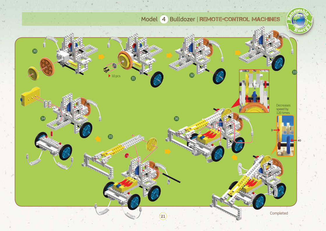
REMOTE-CONTROL MACHINES | Model 4 Bulldozer
Size (cm) : 32 (L) x 16 (W) x 21 (H)
1
2
5
6
7
8
3
4
Make a goal area with some other building blocks or some cardboard pieces (not included in this kit) as shown here.
How to Operate:1. Turn on the switch on
the remote control-ler.
2. Touch the touch pad 3 on the remote
controller briefly at first and then the touch pads 3 and 1 together at the same time so that the bulldozer will turn slightly clockwise at first and then head forward.
3. Touch the touch pad 2 to raise the blade and the touch pad 5 to lower it back down. Don't raise the blade higher than 90 degrees.
Challenge:
Use the remote controller to move blocks into a des-ignated area with the blade of the bulldozer.
● The gears and wheels on the drive axles must be kept 1 mm away from the frame so that they can turn smoothly.
● Use the end of the part separator tool marked with "A" to pry up the anchor pin.
● If the motor doesn’t work, check to make sure the wire connec-tor of the geared motor and the output of the receiver/battery holder are well connected, or that the batteries are not dead.
13
46
2 5
136
31
+64
+
4
Tips for Assembly:

19
Model 4 Bulldozer | REMOTE-CONTROL MACHINES
9
12
13 14
15
16 17 1819
10
11

20
REMOTE-CONTROL MACHINES | Model 4 Bulldozer
20
21
22
23
24
25
2627
28
29
21
Model 4 Bulldozer | REMOTE-CONTROL MACHINES
Completed
30
3132
33
34
35
36
Decreases speed by 120 times
40
3
10 pcs

22
Size (cm) : 21 (L) x 15 (W) x 15 (H)
REMOTE-CONTROL MACHINES | Model 5 Antique Car
1
2
3
4
Draw a square or put a sheet of paper on the ground to form a parking spot. Try to control the car to move backward, and see if you can park it perfectly inside the lines of the parking spot.
● The wheels and drive chain must be kept 1 mm away from the frame so that they can turn smoothly.
● Use the end of the part separator tool marked with "A" to pry up the anchor pin.
● If the motor doesn’t work, check to make sure the wire connector of the motor and the output of the receiver/battery holder are well connected, or that the batteries are not dead.
How to Operate:
Challenge:
Park the antique car in a certain area backward with the remote controller.
1. Turn on the switch on the remote controller.
2. Touch the touch pad 3 or 6 on the remote
controller to make the model car turn clockwise or counter-clockwise.
3. Touch the touch pad 1 or 4 on the remote controller to make the model car drive forward or backward.
13
46
36
14
Tips for Assembly:

23
Model 5 Antique Car | REMOTE-CONTROL MACHINES
5
9
10
1112
6
78

24
REMOTE-CONTROL MACHINES | Model 5 Antique Car
Completed
13
16
17
18
19
1415
Decreases speed by 3 times
Decreases speed by 20 times
20
3
39 pcs
25
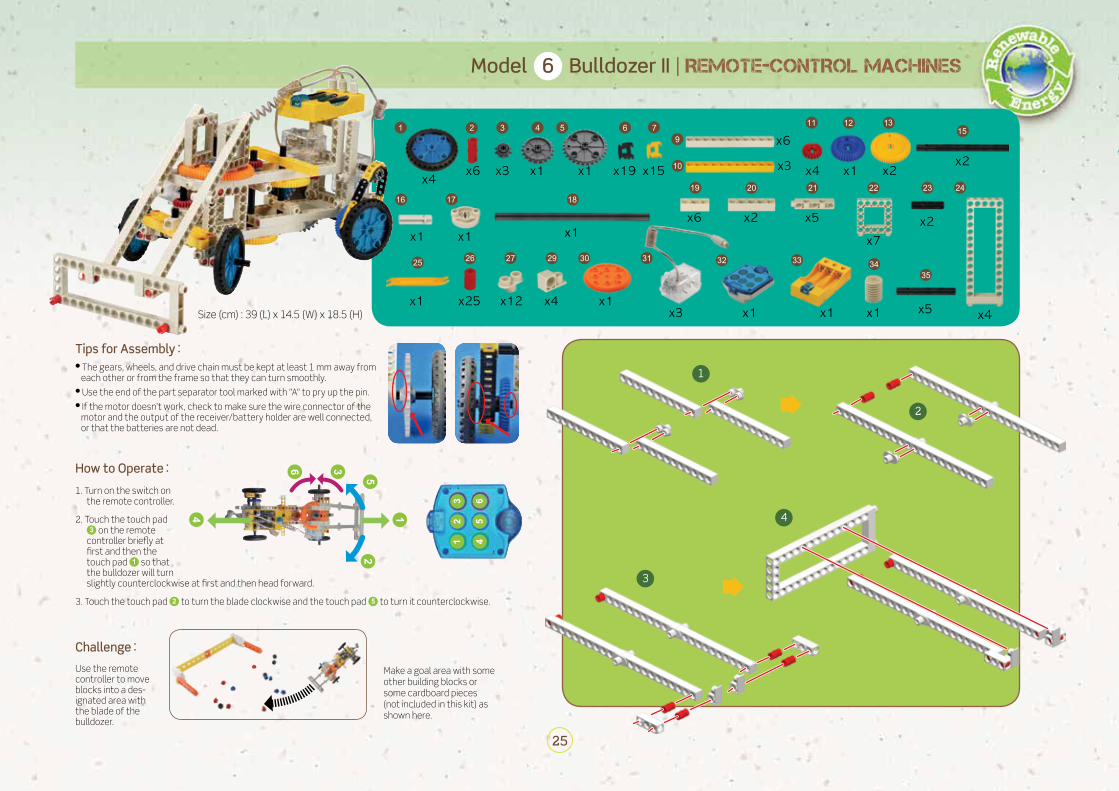
Model 6 Bulldozer II | REMOTE-CONTROL MACHINES
1
2
3
4
Size (cm) : 39 (L) x 14.5 (W) x 18.5 (H)
How to Operate:1. Turn on the switch on
the remote controller.
2. Touch the touch pad 3 on the remote
controller briefly at first and then the touch pad 1 so that the bulldozer will turn slightly counterclockwise at first and then head forward.
3. Touch the touch pad 2 to turn the blade clockwise and the touch pad 5 to turn it counterclockwise.
Challenge:
● The gears, wheels, and drive chain must be kept at least 1 mm away from each other or from the frame so that they can turn smoothly.
● Use the end of the part separator tool marked with "A" to pry up the pin.● If the motor doesn’t work, check to make sure the wire connector of the
motor and the output of the receiver/battery holder are well connected, or that the batteries are not dead.
13
46
2 5
1
25
4
36
Tips for Assembly:
Make a goal area with some other building blocks or some cardboard pieces (not included in this kit) as shown here.
Use the remote controller to move blocks into a des-ignated area with the blade of the bulldozer.

26
REMOTE-CONTROL MACHINES | Model 6 Bulldozer II
The motor should be installed after the medium axle is connected to the worm gear.
5
910
1112
13
14 15
6
7
8

27
Model 6 Bulldozer II | REMOTE-CONTROL MACHINES
16
19 20
21
17
18
28
REMOTE-CONTROL MACHINES | Model 6 Bulldozer II
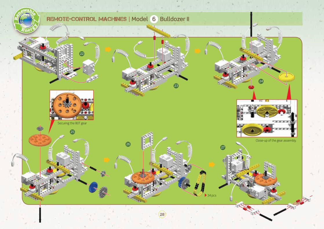
Securing the 80T gear
Close-up of the gear assembly.
22
23
25
2627
24
34 pcs

29
Model 6 Bulldozer II | REMOTE-CONTROL MACHINES
28
32
33
29
30
31
CompletedAdjust the blade to make the bulldozer work correctly.
Decreases speed by 20 times
Decreases speed by 2 times
Decreases speed by 36 times
20
2
4 3
3

30
REMOTE-CONTROL MACHINES | Model 7 Folding Car
Size (cm) : 34 (L) x 17.5 (W) x 14 (H)
1
2
3
4
Pay attention to the direction of the S. gear.
Draw a square or put a sheet of paper on the ground to form a parking spot. Try to control the car to move it backward, and see if you can park it perfectly in the parking spot.
● The red gears on the drive axle must be kept 1 mm away from the rod so that they can turn smoothly.
● Use the end of the part separator tool marked with "A" to pry up the anchor pin.
● If the motor doesn’t work, check to make sure the wire con-nector of the motor and the output of the receiver/battery holder are well connected, or that the batteries are not dead.
Challenge:
Park the folding car in a designated area backward using the remote controller.
31
+
64
+
13
46
2 5
31
64
How to Operate:
1. Turn on the switch on the remote controller.
2. Touch the touch pads 3 and 4(or 1 and 6 ) together at the same time, and the car will keep turning around.
3. Touch the touch pads 3 and 1 (or 6 and 4 ) together at the same time, and the car will go forward (or backward).
4. Touch the touch pad 2 to activate the car’s folding mechanism and touch the touch pad 5 to release it.
Tips for Assembly:
2

31
Model 7 Folding Car | REMOTE-CONTROL MACHINES
56
7
8 9
10

32
REMOTE-CONTROL MACHINES | Model 7 Folding Car
11 12
13
14
15
Decreases speed by
120 times
Completed
3 40
33
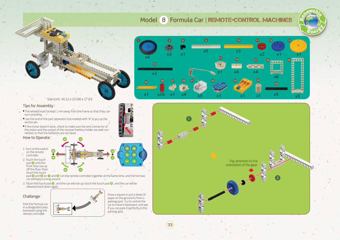
Model 8 Formula Car | REMOTE-CONTROL MACHINES
1
2
Size (cm) : 41 (L) x 23 (W) x 17 (H)
Pay attention to the orientation of the gear.
How to Operate:
1. Turn on the switch on the remote controller.
2. Touch the touch pad 2 until the front tires rise up off the floor, then touch the touch pad 3 and 4 (or 1 and 6 ) on the remote controller together at the same time, and the formula car will keep turning around.
3. Touch the touch pad 2 , and the car will rise up; touch the touch pad 5 , and the car will be released back down again.
Challenge:
● The wheels must be kept 1 mm away from the frame so that they can turn smoothly.
● Use the end of the part separator tool marked with "A" to pry up the anchor pin.
● If the motor doesn’t work, check to make sure the wire connector of the motor and the output of the receiver/battery holder are well con-nected, or that the batteries are not dead.
Draw a square or put a sheet of paper on the ground to form a parking spot. Try to control the car to move it backward, and see if you can park it perfectly in the parking spot.
Park the formula car in a designated area backward using the remote controller.
13
46
2 5
31
+
64
+
31
64
Tips for Assembly:

34
REMOTE-CONTROL MACHINES | Model 8 Formula Car
3
4
5
7
6
8 9

35
Model 8 Formula Car | REMOTE-CONTROL MACHINES
10
1112
13 14

36
REMOTE-CONTROL MACHINES | Model 8 Formula Car
Completed
Decreases speed by 120 times
15
16
17
3 40
Make a goal area with some other building blocks or some cardboard pieces (not included in this kit) as shown here.
Use the remote controller to move blocks into a des-ignated area with the blades of the bulldozer.
37
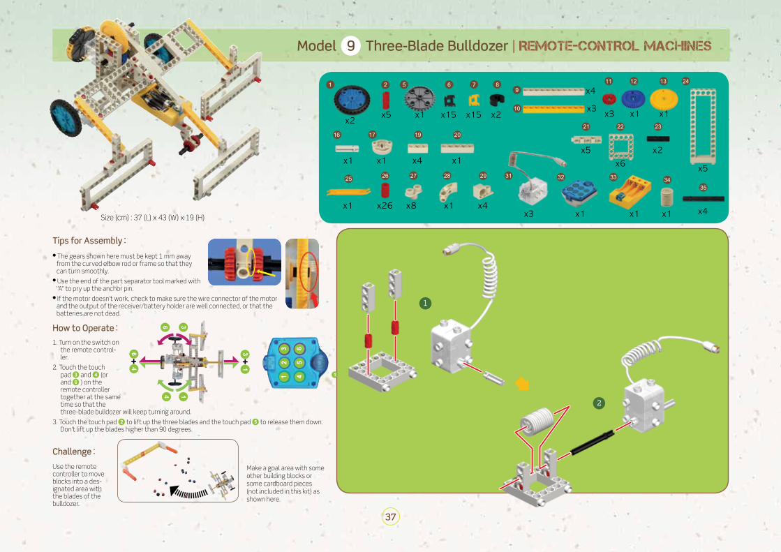
Model 9 Three-Blade Bulldozer | REMOTE-CONTROL MACHINES
Size (cm) : 37 (L) x 43 (W) x 19 (H)
1
2
How to Operate:1. Turn on the switch on
the remote control-ler.
2. Touch the touch pad 3 and 4 (or 1 and 6 ) on the remote controller together at the same time so that the three-blade bulldozer will keep turning around.
3. Touch the touch pad 2 to lift up the three blades and the touch pad 5 to release them down. Don't lift up the blades higher than 90 degrees.
Challenge:
● The gears shown here must be kept 1 mm away from the curved elbow rod or frame so that they can turn smoothly.
● Use the end of the part separator tool marked with "A" to pry up the anchor pin.
● If the motor doesn’t work, check to make sure the wire connector of the motor and the output of the receiver/battery holder are well connected, or that the batteries are not dead.
31
+
64
+
13
46
2 5
64
31
Tips for Assembly:

38
REMOTE-CONTROL MACHINES | Model 9 Three-Blade Bulldozer
3
4
5
6
7
8

39
Model 9 Three-Blade Bulldozer | REMOTE-CONTROL MACHINES
9
1011
12
13
30 pcs

40
REMOTE-CONTROL MACHINES | Model 9 Three-Blade Bulldozer
14
15
16
1718

41
Model 9 Three-Blade Bulldozer | REMOTE-CONTROL MACHINES
19
22
2324
25
26
20
21

42
REMOTE-CONTROL MACHINES | Model 9 Three-Blade Bulldozer
Completed
Decreases speed by 120 times
The angle of the blade can be adjusted by hand.
27 28
29
40 3

43
Model 10 Robotic Arm | REMOTE-CONTROL MACHINES
Size (cm) : 32 (L) x 16 (W) x 28 (H)
How to Operate:
1. Turn on the switch on the remote controller.
2. Touch the touch pad 3 or 6 on the remote con-troller to close or open the gripper.
3. Touch the touch pad 2 or 5 to turn the whole arm clockwise or counterclockwise. Don't turn it more than 180 degrees.
4. Touch the touch pad 1 or 4 to lower or raise the arm. Don't raise it up higher than 90 degrees.
● Press the gear A downward and gear B upward to secure the 80T gear in place.
● Always keep the gear against the middle of the worm gear when they are to be meshed together. In this way they will run smoothly.
● Keep the drive axle shown here steady by pressing the red gear A downward, red gear B upward, and moving red gear C down to mesh with the worm gear.
A
B
AB
C1 2
3
41 3
4 6
2
5
54
36
12
Tips for Assembly:

44
REMOTE-CONTROL MACHINES | Model 10 Robotic Arm
5
6
7
8
9
10
11

45
Model 10 Robotic Arm | REMOTE-CONTROL MACHINES
Insert the shaft pin to secure the large gear first, and then insert the medium axle.
12
1314
15
16
17
18
A

46
REMOTE-CONTROL MACHINES | Model 10 Robotic Arm
19
23
24
25
20
21
22

47
Model 10 Robot | REMOTE-CONTROL MACHINES
Completed
26
27
28
Decreases speed by 60 times
Decreases speed by 80 times
Decreases speed by 60 times
Set up challenges for your robotic arm. For example, try moving a paper cup.
A
60
20
4
60

© Genius Toy Taiwan Co., Ltd., Taichung, Taiwan, R.O.C.7th Edition © 2010, 2012, 2014, 2015, 2016, 2017 Thames & Kosmos, LLC, Providence, RI, USAThames & Kosmos® is a registered trademark of Thames & Kosmos, LLC.
This work, including all its parts, is copyright protected. Any use outside the specific limits of the copyright law without the consent of the publisher is prohibited and punishable by law. This applies specifically to reproductions, translations, microfilming, and storage and processing in electronic systems and networks. We do not guarantee that all material in this work is free from copyright or other protection.
Manual illustrations and photos: Genius Toy Taiwan Co., Ltd., Taichung, Taiwan, R.O.C., and Thames & Kosmos
The publisher has made every effort to locate the holders of image rights for all of the photos used. If in any individual cases any holders of image rights have not been acknowledged, they are asked to provide evidence to the publisher of their image rights so that they may be paid an image fee in line with the indus-try standard.
Distributed in North America by Thames & Kosmos, LLC. Providence, RI 02903 Phone: 800-587-2872; Web: www.thamesandkosmos.com
Distributed in United Kingdom by Thames & Kosmos UK LP. Cranbrook, Kent TN17 3HEPhone: 01580 713000; Web: www.thamesandkosmos.co.uk
We reserve the right to make technical changes.
Printed in Taiwan / Imprimé en Taiwan
FCC Part 15 StatementThis device complies with Part 15 of the FCC Rules. Operation is subject to the following two conditions: (1) this device may not cause harmful interference, and (2) this device must accept any interference received, including interference that may cause undesired operation.
Changes or modifications not expressly approved by the party responsible for compliance could void the user’s authority to operate the equipment.
NOTE: This equipment has been tested and found to comply with the limits for a Class B digital device, pursuant to Part 15 of the FCC Rules. These limits are designed to provide reasonable protection against harmful interference in a residential installation. This equipment generates, uses and can radiate radio frequency energy and, if not installed and used in accordance with the instructions, maybe cause harmful interference to radio communications. However, there is no guarantee that interference will not occur in a particular installation. If this equipment does cause harmful interference to radio or television reception, which can be determined by turning the equipment off and on, the user is encouraged to try to correct the interference by one or more of the following measures:
- Reorient or relocate the receiving antenna.
- Increase the separation between the equipment and receiver.
- Connect the equipment into an outlet on a circuit different form that to which the receiver is connected.
- Consult the dealer or an experienced radio/TV technician for help.
5550
04-0
2-09
1017