experimental and numerical investigation of i 65⁰...
TRANSCRIPT

International Journal of Mechanical & Mechatronics Engineering IJMME-IJENS Vol:19 No:05 115
192005-4343-IJMME-IJENS © October 2019 IJENS I J E N S
Abstract— In this study, a circular cylinder cut by 65 degrees
on both sides was placed aligned with the axis returning turbine
vane of a Savonius rotor turbine. This type of cylinder is called
an I-65⁰ type cylinder and is designed to bring down the drag
forces on the returning blade, aerodynamically. Wind turbine
performance was investigated experimentally and numerically
under two conditions, with and without the installation of a type
I-65⁰ cylinder in line with a horizontal axis returning turbine
blade. The study was conducted with Reynolds number Re = 9.9 x
104 based on free stream velocity (U) 5 m/s and a characteristic
length L = 2D-b, where D is the outer diameter of the vane and b
is the diameter of the rod. The I-65⁰ type cylinder, which has a
diameter of 0.5D, is placed at a distance of 1.4D in front of the
returning turbine blade. In numerical studies, a 3D simulation
was conducted to analyze the Savonius turbine flow using
Commercial CFD software, Ansys Fluent version 19.1. The
experimental output shows that installing an I-65⁰ type cylinder
in front of the returning blade can increase the Cp of the
Savonius turbine. Compared to the conventional turbine, the
maximum power coefficient of the Savonius turbines increased to
around 23.6% due to the installation of an I-65⁰ type cylinder,
and this was achieved at a tip-speed ratio (TSR) of 0.8. This result
is justified by numerical results carried out in this study.
Index Term— Savonius turbine; I-65⁰ type cylinder; returning
blade; performance; transient; sliding mesh.
I. INTRODUCTION
In order to participate in efforts to increase new and renewable
energy sources, many studies have conducted that utilize
environmentally friendly sources of energy such as wind
energy, ocean energy, biomass, solar energy, and geothermal
energy. Wind energy is one of the abundant and easily found
resources around us, where a turbine is needed to take
advantage of it. The Savonius rotor turbine is one of Vertical
Axis Wind Turbine (VAWT), which is quite common in
construction, independent from wind direction, and proof to
rotate at relatively low wind speed. The Savonius rotor turbine
spinning in consequence of the difference in drag pressure
between the returning blade and the advancing blade as an
aerodynamic reaction from the airflow that crossed the
turbine. Based on its principle operation, the Savonius rotor
turbine is also named as drag type turbine. This type of turbine
has a unique advantage where the turbine is capable of
rotating on its own even though the airspeed through it is very
low. With this behavior, the turbine suitable for the area where
there are low wind speed and no need external push support
device. However, this type of rotor turbine has a weak
coefficient of power compared to other types of rotor turbines.
This is what emphasizes the importance of various studies
conducted in order to augment the performance of the
Savonius rotor turbine. Figure. 1. shows the comparison of
performance between several types of wind turbines expressed
in the Coefficient of Power (Cp) as a function of the Tips-
Speed Ratio (λ). It presented that the Savonius rotor turbine
has a maximum Cp of probably 18%-20% at TSR: 0.7-0.8.
This performance is stated to be the lowest between other
types of Savonius rotor turbines. This accomplishment of the
Savonius turbine also has been investigated by many authors
from 1977 until 2019 to specify the perfect design parameters.
Nevertheless, the most popular wind turbines currently are
ideal propellers, which is the power coefficient directly
proportional to the tips-speed ratio. The following are some of
the studies that will be discussed as a sustainable principle of
this report.
Fig. 1. Power coefficient function Tip-Speed Ratio (λ) for various wind
turbines Morshed K.N. [1].
Experimental and Numerical Investigation of I-
65⁰ Type Cylinder Effect on the Savonius Wind
Turbine Performance
Gunawan Sakti1,4 Triyogi Yuwono2,3* Wawan Aries Widodo2,
1Graduate Student in the Department of Mechanical Engineering, Institut Teknologi Sepuluh
Nopember, 2Department of Mechanical Engineering, Institut Teknologi Sepuluh Nopember,
3Center of Excellence in Automotive Control & System, Institut Teknologi Sepuluh Nopember,
Kampus Keputih-Sukolilo, Jl. Arif Rahman Hakim, Surabaya, 60111, Indonesia, 4Aircraft Maintenance Engineering Technology AMTO147D-010, Politeknik Penerbangan Surabaya,
Jl. Jemur Andayani I No.73 Wonocolo, Surabaya, 60236, Indonesia
*Corresponding Author: [email protected]
International Journal of Mechanical & Mechatronics Engineering IJMME-IJENS Vol:19 No:05 116
192005-4343-IJMME-IJENS © October 2019 IJENS I J E N S
The experimental method for reducing the main cylinder drag
by installed I-type bluff body cut performed by [2]. The I-type
bluff body cut off in several scission angles between
0⁰≤θs≤65⁰ were installed in upstream and aligned at the line
axis of the main cylinder at a distance S/d =1.375. The result
presented that optimum drag reduction is obtained in the bluff
body within cutting angle 65⁰, Reynolds number Re = 5.3 x
104, which is the primary cylinder drag decreased up to 52%.
Investigation of the Installation D-shape and I-shape cylinder
in front of the primary cylinder circular conducted by [3]. The
ranges of cutting angles for both shape cylinders between 50⁰-
53⁰ and the Reynolds number Re > 2.3 x 10⁴. The output
shows that the wake behind the main cylinder becomes
narrowed, and vortex arises downstream. The experimental
investigation of the bluff body cut related to the flow
characteristics from the circular cylinder reported by [4]. The
bluff body volume reduction is identic to d/2( 1 — cos θs),
where d and θs defined as the diameter and the position angles,
respectively. Where θs are stretched in the interval 0⁰ ≤ θs, ≤
72.5⁰, and Reynolds Number Re = 2.0 x 10⁴ and 3.5 x 10⁴. The
result shows the optimum decrease in the drag coefficient CD
is obtained at θs = 53⁰ when Re > 2.5 x 10⁴. Whereas for
Re=3.1×10⁴ and θs > 60◦, the coefficient drag CD is higher
than the circular one for the D-type. The other reports by [5],
experimentally put down the rod upstream circular cylinder
with diameter D = 40 mm. The rod diameter varies from 1 ≤ d
≤ 10 mm, the spaces from center to center between main
cylinder and rod 50 < L < 120 mm and Reynolds Number Re =
1.5 x 10⁴ – 6.2 x 10⁴. The result show the peak conditions of
the pressure drag reductions are d/D = 0.25, L/D = 1.75-2.0. In
these ways, the drag reduced up to 63% contrast with a normal
cylinder. The experimental investigation corresponds to the
installation of a small control rod in the direction of airflow or
upstream the central cylinder executed by [6]. The control rod
diameter (d) varies between 0.133 ≤ d/D ≤ 0.267, where D is
defined as the diameter of the main cylinder (30 mm). The
coefficient of drag of the main cylinder dropped about 29%
when a regulator rod with the diameter d = 7mm (d/D = 0.233)
is mounted at a ratio of the pitch near to the significant value
of Lc/D =2.081. Concerning the study about the Savonius
turbine, the scientific reports [7] investigated the installation
of a curtain upstream of the Savonius rotor turbine in order to
disappear returning blade negative moments within both
numerical and experimental approaches. Performance
investigation carried out with the use and unused curtain
installation. The result shows that significantly increased in
Savonius rotor turbine performance has been achieved by the
installation of the curtain. The curtain varies in dimension
involved of both side parts length (ℓ1 and ℓ2) and angles (α and
β). The Power Coefficient (Cp) increase up to 38.5 % with
optimal curtain dimension ℓ1 = 45 cm and ℓ2 = 52 cm and α =
45o and β = 15o. The research reports [8] investigated
experimentally in order to improve the final power parameters
of the Savonius rotor turbine include the static moments,
which calculated the turbine's self-starting capability. Both
objectives achieved by the geometry skeleton line that is
maximalized in the existence of the disturbance plate. The
result shows that the turbine’s coefficient of power climb up to
40% at the tip-speed ratio TSR (λ) = 0.7. The static torque as a
benchmark of self-starting ability strengthened in the positive
area at any angle, it means the turbine no need external
devices to rotate. The investigation in diverse Savonius
geometries is conducted experimentally with the intention to
decide the most successful operation parameters involved in
power coefficients and static torque carry out by [9]. The
results show that two blades rotor, rotor with endplates,
second stages rotor, and rotor without overlap is more efficient
than the others. The investigation proves that the aspect ratio
directly proportional to the power coefficient. Static torque
measurement of all types of rotors at different speeds verify
the results of the investigation. The corresponding reports by
[10] have studied numerically about the impact of the breadth
of a unique curtain on the capability of the Savonious rotor
turbine. They proved that the installing of the curtain in front
of the returning blade of the turbine for improving the
performance of the turbine is dependent on the width of the
curtain and the Reynolds number. For the width of the large
curtain of S/D = 2.0 at Re = 9 x 10⁴, the performance of the
turbine is estimated lower than when the turbine without the
curtain. In the same case, the scientific reports [11] have also
investigated the problem experimentally. They also proved
that the placement of the curtain plate in front of the convex
blade for improving the performance of the turbine depends on
the breadth of the curtain plate and the Re. Where for the
wider curtain (S/D>1.4) at Re = 9 x 10⁴, the coefficient of
power turbine is less than when the turbine without the curtain
plate. In this way, the Cp of the turbine with the curtain plate
may fall to 60.8% of the turbine without the curtain plate, for
S/D = 1.83 at Re = 9 x 10⁴. The numerical investigation related
to the Savonius wind turbine with Novel blade shapes
developed from Myring Equation performed by [12]. The
results show that the effect of blade fullness increased peak
power coefficient 10.98% higher than conventional Savonius
wind turbine obtained at tips speed ratio 0.8.
According to the above summarize, this study is conducted
in objectives to improve the performance of the Savonius rotor
turbine experimentally and numerically by mounting an I-65⁰
type cylinder upstream convex of the turbine. The
experimental is performed by decided the center to center
distance between axes of returning blade and I-65⁰ cylinder
S/D = 1.4 and at Reynolds Number Re = 9.9 x 10⁴. The
numerical computation is conducted by use commercial solver
ANSYS-Fluent 19.1 in order to validate the experimental data
and recognized the flow behavior at an adjacent turbine wall.
According to Triyogi et al. [2], that an I-65o type cylinder gives the highest reduction in drag of the main cylinder behind
it, due to the highest drag coefficient (CD) of the I-65o type
cylinder. As it is known that the highest CD is generally due to
the broader wake region behind the cylinder, so the shear layer
of the I-65o type cylinder is most effective in affecting a bluff
body in the downstream. Inspired by Triyogi et al. [2], the idea
of using a type I-65o cylinder, as a passive control, mounted
upstream of the convex blade is intended to reduce the drag
force of the convex blade so that positive torque increases and
ultimately increases Savonius turbine power.
International Journal of Mechanical & Mechatronics Engineering IJMME-IJENS Vol:19 No:05 117
192005-4343-IJMME-IJENS © October 2019 IJENS I J E N S
II. METHODS
A. Experimental Arrangement
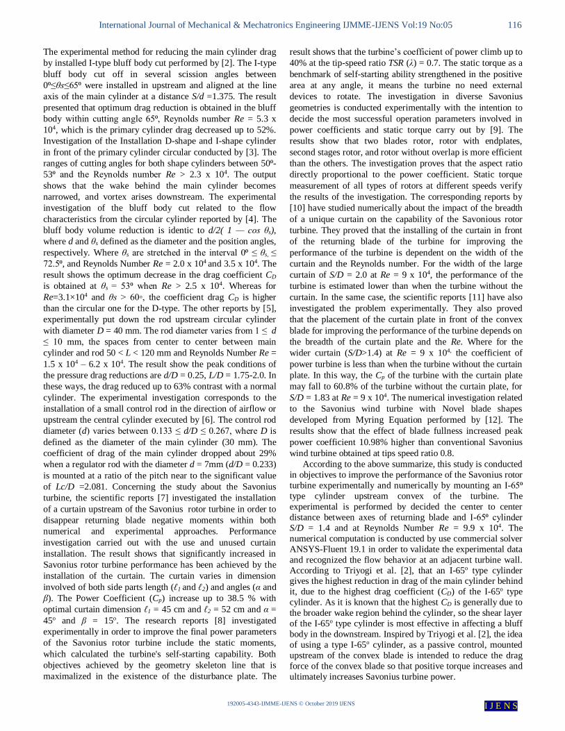
Figure 2a describes the Savonius wind turbine configuration
with the installation I-65⁰ type cylinder cut upstream returning
blade, where this I-65⁰ type cylinder cut is a circular cylinder
with d = 88.5 mm in diameter cut at both sides in parallel with
y-axis. The turbine constructed from polyvinyl chloride plastic
material with blade diameter D = 165.2 mm, it gives the d/D =
0.54 (this diameter size is chosen without special
consideration, but a similar research is currently being carried
out for variations in circular cylinder diameters sizes by other
groups at the same laboratory) and height H = 294.4 mm, with
the shaft diameter b = 19 mm. The turbine rotor is equipped
with an end-plate that has a diameter of 333.7 mm. The I-65⁰
type cylinder is also assembled by polyvinyl chloride plastic
material whose height is 500 mm installed in the upstream
returning blade. The I-65⁰ type cylinder is also set within
distance center to center relative to the turbine diameter S/D =
1.4. This is because, according to Triyogi et al. [2], small-type
I cylinder with cutting angles θs = 65⁰ and mounted at the
distance S/D=1.4 in front of the main cylinder give the highest
drag reduction among the small cylinders tested in their
investigation. Also, based on the results theses of Sakti [13],
that placing an I-65o type cylinder upstream the convex blade
at a distance relative to the blade diameter S/D = 1.4 provides
the highest increase in Savonius turbine power, among other
distances tested in his study. The experiments are conducted
with freestream speed (U) of 5 m/s coincide to Re = 9.9x10⁴.
The Reynolds Number is obtained from the length of
characteristic L = (2D-b) and free stream speed (U) from the
blower. Figure 2b describes the turbine dynamics moment that
is measured by a rope-brake type dynamometer, based on
research Mahmoud et al., Kadam & Patil [9, 14] as references.
The rope-brake dynamometer assembly contains pulley,
weighing pan, spring balanced, and nylon string. The
weighing pan is linked by spring balance with nylon string 1.0
mm in diameter, were the wire string is wrapped one loop over
the pulley.
Fig. 2. (a). The Savonius wind turbine configuration with an I-65⁰ type
cylinder is installed in front of Returning Blade. (b). The Schematic diagram
of rope-brake dynamometer measurement
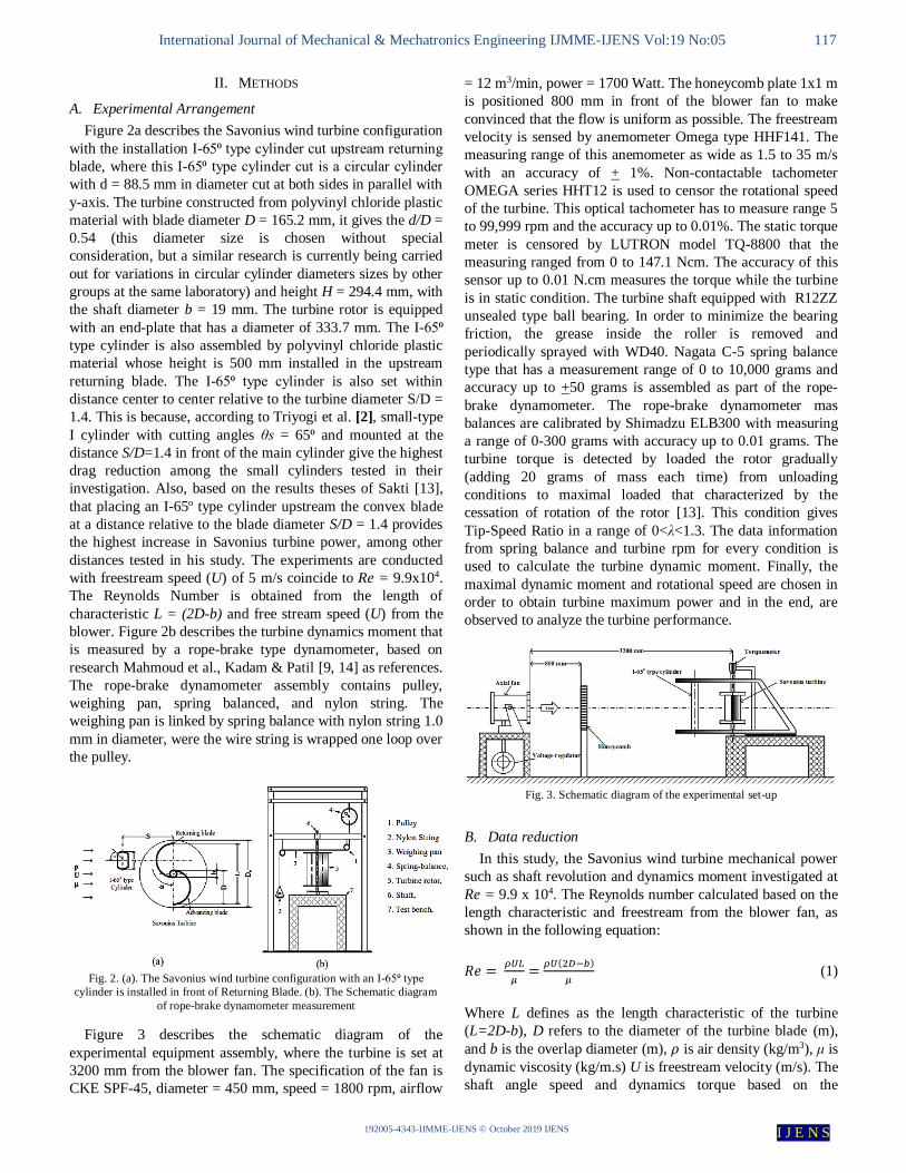
Figure 3 describes the schematic diagram of the
experimental equipment assembly, where the turbine is set at
3200 mm from the blower fan. The specification of the fan is
CKE SPF-45, diameter = 450 mm, speed = 1800 rpm, airflow
= 12 m3/min, power = 1700 Watt. The honeycomb plate 1x1 m
is positioned 800 mm in front of the blower fan to make
convinced that the flow is uniform as possible. The freestream
velocity is sensed by anemometer Omega type HHF141. The
measuring range of this anemometer as wide as 1.5 to 35 m/s
with an accuracy of + 1%. Non-contactable tachometer
OMEGA series HHT12 is used to censor the rotational speed
of the turbine. This optical tachometer has to measure range 5
to 99,999 rpm and the accuracy up to 0.01%. The static torque
meter is censored by LUTRON model TQ-8800 that the
measuring ranged from 0 to 147.1 Ncm. The accuracy of this
sensor up to 0.01 N.cm measures the torque while the turbine
is in static condition. The turbine shaft equipped with R12ZZ
unsealed type ball bearing. In order to minimize the bearing
friction, the grease inside the roller is removed and
periodically sprayed with WD40. Nagata C-5 spring balance
type that has a measurement range of 0 to 10,000 grams and
accuracy up to +50 grams is assembled as part of the rope-
brake dynamometer. The rope-brake dynamometer mas
balances are calibrated by Shimadzu ELB300 with measuring
a range of 0-300 grams with accuracy up to 0.01 grams. The
turbine torque is detected by loaded the rotor gradually
(adding 20 grams of mass each time) from unloading
conditions to maximal loaded that characterized by the
cessation of rotation of the rotor [13]. This condition gives
Tip-Speed Ratio in a range of 0<λ<1.3. The data information
from spring balance and turbine rpm for every condition is
used to calculate the turbine dynamic moment. Finally, the
maximal dynamic moment and rotational speed are chosen in
order to obtain turbine maximum power and in the end, are
observed to analyze the turbine performance.
Fig. 3. Schematic diagram of the experimental set-up
B. Data reduction
In this study, the Savonius wind turbine mechanical power
such as shaft revolution and dynamics moment investigated at
Re = 9.9 x 10⁴. The Reynolds number calculated based on the
length characteristic and freestream from the blower fan, as
shown in the following equation:
𝑅𝑒 = 𝜌𝑈𝐿
𝜇=
𝜌𝑈(2𝐷−𝑏)
𝜇 (1)
Where L defines as the length characteristic of the turbine
(L=2D-b), D refers to the diameter of the turbine blade (m),
and b is the overlap diameter (m), 𝜌 is air density (kg/m3), μ is
dynamic viscosity (kg/m.s) U is freestream velocity (m/s). The
shaft angle speed and dynamics torque based on the
International Journal of Mechanical & Mechatronics Engineering IJMME-IJENS Vol:19 No:05 118
192005-4343-IJMME-IJENS © October 2019 IJENS I J E N S
experiment result is used to determine the mechanical power
Pm with the following equation;
𝑃𝑚 = 𝑇𝜔 (2)
Where the letter T as dynamic torque (N.m), ω is shaft angle
speed or angular velocity (rad/s). Individually the active
torque is calculated with the following equation:
𝑇 = 𝐹𝑟 (3)
Where r expressed as the radius of the pulley and the letter F
is the force step on the rotor shaft that could be determined
with the following equation:
𝐹 = (𝑀 − 𝑠)𝑔 (4)
The angular velocity ω could be calculated by the equation
below:
𝜔 =2𝜋𝑁
60 (5)
Where the letter N expressed as the number revolution per
minute (rpm). The coefficient of a moment for each turbine
blade determined for a sequence with calculated the swept
area before by using the following equation:
𝐴 = 𝐻𝐷 (6)
Where A defines as the swept area (m2), and the letter H
described as the height of the rotor (m). Then the following
equation uses to calculate the coefficient moment.
𝑐𝑚 =4𝑇
𝜌𝐴𝐿𝑉2 (7)
After getting the angular speed ω, the tip speed ratio TSR or λ
determined with the following equation below:
𝑇𝑆𝑅 = 𝜆 =𝜔𝐿
2𝑉 (8)
The coefficient power is the power efficiency of the turbine or
ratio between turbine power input and turbine power output
that could be determined by the following equation:
𝐶𝑝 =𝑃𝑚
𝑃𝑤
(9)
Where Pw defines as wind power act as input, and Pm described as mechanical power act as an output. The wind power Pw
could be determined by the equation below:
𝑃𝑤 = 1
2𝜌𝐴𝑈3 (10)
In the fullness of time, refers to the (2), (3), (4), (5), (9), and
(10) the power coefficient determined by the equations below:
𝑐𝑝 =𝑔𝑟𝑁(𝑀−𝑠)
15𝜌𝐴𝑈3 (11)
Based on the multiplication between of coefficient moment
and tips speed ratio found the alternatives equation in order to
calculated coefficient power as explained below;
𝑐𝑝 =𝑃𝑚
0.5𝜌𝐴𝑈3 (12)
Based on Young D. Hugh (1962), the uncertainty value is a
critical consideration in an experimental study [18]. Table 1
presented the uncertainty of coefficient moment and
coefficient power that computed at the maximum amount of
5.2% and 5.3%, respectively.
TABLE 1
THE UNCERTAINTY COMPUTATION RESULT FOR SEVERAL PARAMETERS
Parameter Uncertainty (%)
Reynolds Number
Coefficient Moment
Coefficient Power
Tips Speed Ratio
2.7
5.2
5.3
2.0
C. Numerical analysis
Based on the literature, it can be understood that a
precision CFD simulation of the flow behavior near Savonius turbine is very complex and crucial work, primarily due to its
time consuming and the system efficiency strongly influences
by flow separation. Therefore it is essential to observe the
simulation procedures carefully with full attention. Following
the series of that procedures, the results of the numerical
simulation approach must be validated.
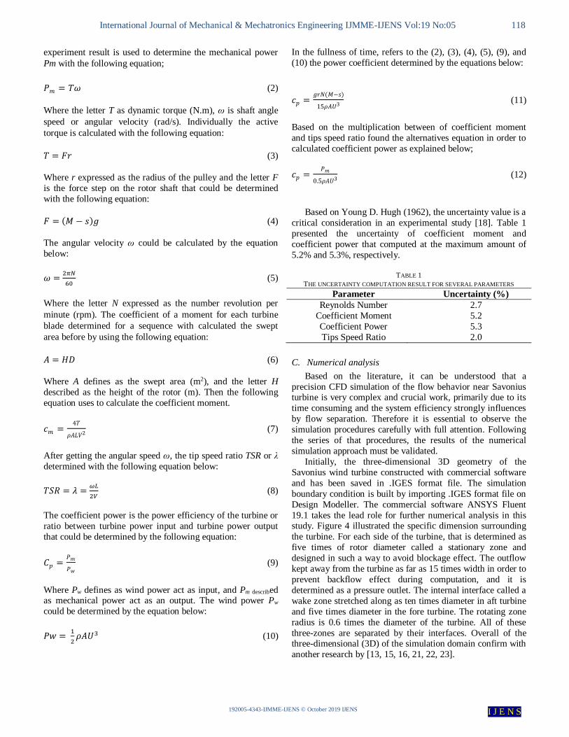
Initially, the three-dimensional 3D geometry of the
Savonius wind turbine constructed with commercial software
and has been saved in .IGES format file. The simulation
boundary condition is built by importing .IGES format file on
Design Modeller. The commercial software ANSYS Fluent
19.1 takes the lead role for further numerical analysis in this study. Figure 4 illustrated the specific dimension surrounding
the turbine. For each side of the turbine, that is determined as
five times of rotor diameter called a stationary zone and
designed in such a way to avoid blockage effect. The outflow
kept away from the turbine as far as 15 times width in order to
prevent backflow effect during computation, and it is
determined as a pressure outlet. The internal interface called a
wake zone stretched along as ten times diameter in aft turbine
and five times diameter in the fore turbine. The rotating zone
radius is 0.6 times the diameter of the turbine. All of these
three-zones are separated by their interfaces. Overall of the three-dimensional (3D) of the simulation domain confirm with
another research by [13, 15, 16, 21, 22, 23].
International Journal of Mechanical & Mechatronics Engineering IJMME-IJENS Vol:19 No:05 119
192005-4343-IJMME-IJENS © October 2019 IJENS I J E N S
10L 15L
5L
5L
Vel
oci
ty I
nle
t
3L
3L
5L 10L
symmetry
symmetry
Pre
ssu
re o
utl
et (
Pat
m)
blades, no
slip wall1.2 L
Z
X
Y
I-65o type
cylinder
Fig. 4. The detailed description of the 3D three-dimensional
computation domain and boundary condition plotted in the y-
axis.
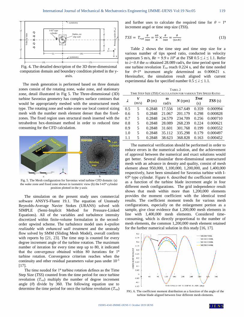
The mesh generation is performed based on three domain
zones consist of the rotating zone, wake zone, and stationary
zone, detail illustrated in Fig 5. The Three-dimensional (3D)
turbine Savonius geometry has complex surface contours that
would be appropriately meshed with the unstructured mesh
type. The rotating zone and wake-zone use local control sizing
mesh with the number mesh element denser than the fixed-
zones. The fixed region uses structural mesh inserted with the
tetrahedron hex-dominant method in order to reduced time
consuming for the CFD calculation.
Fig. 5. The Mesh configuration for Savonius wind turbine CFD domain: (a)
the wake zone and fixed zone shown in isometric view (b) the I-65⁰ cylinder
position plotted in the y-axis
The simulation on the present study uses commercial
software ANSYS-Fluent 19.1. The equation of Unsteady
Reynolds-Average Navier Stokes (URANS) solved with
SIMPLE (Semi-Implicit Method for Pressure-Linked
Equations). All of the variables and turbulence intensity
discretized within finite-volume formulation in the second-
order upwind scheme. The turbulence model uses k-epsilon
realizable with enhanced wall treatment and the unsteady flow solved by SMM (Sliding Mesh Model), overall confirm
with reports by [21, 23]. The time step is counted for every
degree increment angle of the turbine rotation. The maximum
number of iteration for every time step up to 80, it indicated
that the convergence obtained within 80 iterations for 1⁰
turbine rotation. Convergence criterion reaches when the
continuity and other residual parameters value pass under 10-5
[17].
The time needed for 1⁰ turbine rotation defines as the Time
Step Size (TSS) counted from the time period for once turbine
revolution (Trot) multiply the number of degree increment
angle (θ) divide by 360. The following equation use to determine the time period for once the turbine revolution (Trot)
and further uses to calculate the required time for θ = 1⁰
increment angel or time step size (TSS).
𝑇𝑆𝑆 = 𝑇𝑟𝑜𝑡𝜃
360=
60
𝑁×
𝜃
360=
𝜃
(6×𝑁) (13)
Table 2 shows the time step and time step size for a
various number of tips speed ratio, conducted in velocity
upstream 5 m/s, Re = 9.9 x 10⁴ at the TSR 0.5 ≤ λ ≤ 1.1. Refer
to λ=0.8 the ω obtained 28.089 rad/s, the time period spent for one turbine revolution Trot reach 0.224 s, and the time needed
for θ=1⁰ increment angle determined as 0.000621 s.
Hereinafter, the simulation result aligned with current
experimental data for specified number 0.5 ≤ λ ≤ 1.1.
TABEL 2
TIME STEP SIZE (TSS) CALCULATION FOR VARIOUS TIPS SPEED RATIO
λ V
(m/s) D (m)
ω
rad/s N (rpm)
Trot
(s) TSS (s)
0.5 5 0.2848 17.556 167.649 0.359 0.000994
0.6 5 0.2848 21.067 201.179 0.298 0.000828
0.7 5 0.2848 24.579 234.709 0.256 0.000710
0.8 5 0.2848 28.089 268.239 0.224 0.000621
0.9 5 0.2848 31.601 301.768 0.199 0.000552
1.0 5 0.2848 35.112 335.298 0.179 0.000497
1.1 5 0.2848 38.623 368.828 0.163 0.000452
The numerical verification should be performed in order to
reduce errors in the numerical solution, and the achievement
of approval between the numerical and exact solutions would
get better. Several dissimilar three-dimensional unstructured mesh with an advance in density and quality, consist of mesh
element about 950,000, 1,100,000, 1,200,000, and 1,400,000
respectively, have been simulated for Savonius turbine with I-
65⁰ type cylinder. Figure 6. described the coefficient moment
as a function of the turbine blade increment angle in four
different mesh configurations. The grid independence result
shows that mesh within more than 1,200,000 elements
provides the moment coefficient with the identical trend
results. The coefficient moment trends for various mesh
configurations, especially on the enlargement portion as a
sample, give clear evidence that 1,200,000 mesh elements in line with 1,400,000 mesh elements. Considered time-
consuming, which is directly proportional to the number of
mesh elements, the common 1,200,000 mesh element retained
for the further numerical solution in this study [16, 17].
FIG. 6. The coefficient moment distribution as a function of the angle of the
turbine blade aligned between four different mesh elements.
International Journal of Mechanical & Mechatronics Engineering IJMME-IJENS Vol:19 No:05 120
192005-4343-IJMME-IJENS © October 2019 IJENS I J E N S
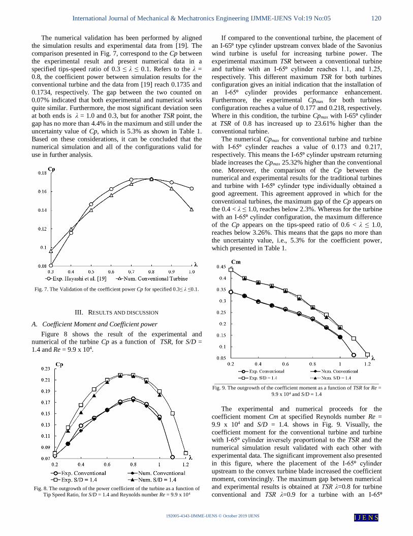
The numerical validation has been performed by aligned
the simulation results and experimental data from [19]. The
comparison presented in Fig. 7, correspond to the Cp between
the experimental result and present numerical data in a
specified tips-speed ratio of 0.3 ≤ λ ≤ 0.1. Refers to the λ =
0.8, the coefficient power between simulation results for the conventional turbine and the data from [19] reach 0.1735 and
0.1734, respectively. The gap between the two counted on
0.07% indicated that both experimental and numerical works
quite similar. Furthermore, the most significant deviation seen
at both ends is λ = 1.0 and 0.3, but for another TSR point, the
gap has no more than 4.4% in the maximum and still under the
uncertainty value of Cp, which is 5.3% as shown in Table 1.
Based on these considerations, it can be concluded that the
numerical simulation and all of the configurations valid for
use in further analysis.
Fig. 7. The Validation of the coefficient power Cp for specified 0.3≤ λ ≤0.1.
III. RESULTS AND DISCUSSION
A. Coefficient Moment and Coefficient power
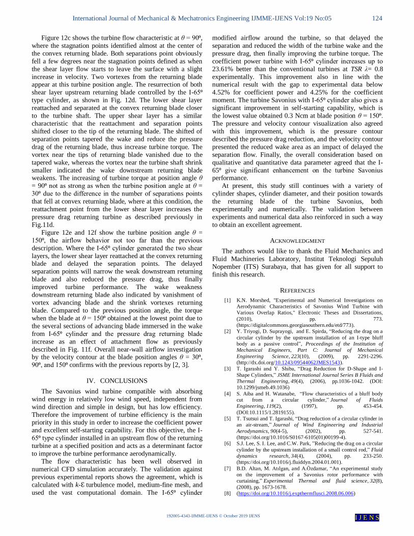
Figure 8 shows the result of the experimental and numerical of the turbine Cp as a function of TSR, for S/D =
1.4 and Re = 9.9 x 10⁴.
Fig. 8. The outgrowth of the power coefficient of the turbine as a function of
Tip Speed Ratio, for S/D = 1.4 and Reynolds number Re = 9.9 x 10⁴
If compared to the conventional turbine, the placement of
an I-65⁰ type cylinder upstream convex blade of the Savonius
wind turbine is useful for increasing turbine power. The
experimental maximum TSR between a conventional turbine
and turbine with an I-65⁰ cylinder reaches 1.1, and 1.25,
respectively. This different maximum TSR for both turbines configuration gives an initial indication that the installation of
an I-65⁰ cylinder provides performance enhancement.
Furthermore, the experimental Cpmax for both turbines
configuration reaches a value of 0.177 and 0.218, respectively.
Where in this condition, the turbine Cpmax with I-65⁰ cylinder
at TSR of 0.8 has increased up to 23.61% higher than the
conventional turbine.
The numerical Cpmax for conventional turbine and turbine
with I-65⁰ cylinder reaches a value of 0.173 and 0.217,
respectively. This means the I-65⁰ cylinder upstream returning
blade increases the Cpmax 25.32% higher than the conventional
one. Moreover, the comparison of the Cp between the numerical and experimental results for the traditional turbines
and turbine with I-65⁰ cylinder type individually obtained a
good agreement. This agreement approved in which for the
conventional turbines, the maximum gap of the Cp appears on
the 0.4 < λ ≤ 1.0, reaches below 2.3%. Whereas for the turbine
with an I-65⁰ cylinder configuration, the maximum difference
of the Cp appears on the tips-speed ratio of 0.6 < λ ≤ 1.0,
reaches below 3.26%. This means that the gaps no more than
the uncertainty value, i.e., 5.3% for the coefficient power,
which presented in Table 1.
Fig. 9. The outgrowth of the coefficient moment as a function of TSR for Re =
9.9 x 10⁴ and S/D = 1.4
The experimental and numerical proceeds for the
coefficient moment Cm at specified Reynolds number Re =
9.9 x 10⁴ and S/D = 1.4. shows in Fig. 9. Visually, the
coefficient moment for the conventional turbine and turbine with I-65⁰ cylinder inversely proportional to the TSR and the
numerical simulation result validated with each other with
experimental data. The significant improvement also presented
in this figure, where the placement of the I-65⁰ cylinder
upstream to the convex turbine blade increased the coefficient
moment, convincingly. The maximum gap between numerical
and experimental results is obtained at TSR λ=0.8 for turbine
conventional and TSR λ=0.9 for a turbine with an I-65⁰

International Journal of Mechanical & Mechatronics Engineering IJMME-IJENS Vol:19 No:05 121
192005-4343-IJMME-IJENS © October 2019 IJENS I J E N S
cylinder type. This particular condition of the maximum gap
calculated reaches 2.65% and 4.25%, respectively. The whole
coefficient moment Cm specific for TSR number ranges to
0.3<λ≤1.0 considered still below the uncertainty value, i.e.,
5.2% from table 1. This means that the deviation of the Cm
value between both turbines configuration still in an acceptable area. Consider the facts founded, the coefficient
moment at all TSR points confirms the improvement of the
turbine performance.
B. Self Starting Capability
Another principal consideration affiliated with turbine performance is the turbine capability for starting its self. In
order to resolve this issue, the experimental static torque
measurement conducted and plotted only in a given angle 0⁰ ≤
θ ≤ 180⁰ due to the periodicity of the turbine rotation [8, 16].
Figure 10 shows the achieved static torque (Ncm) for the
conventional turbine and turbine with an I-65⁰ cylinder
specified at Re = 9.9 x 10⁴. Compared to the conventional
turbine, the experiment result leading to significant
improvement of static torque as an effect of placement I-65⁰
cylinder upstream returning blade. The static torque of the
conventional turbine is partly in the negative domain, e.g., 127⁰≤θ≤163⁰. This negative domain indicates that the
conventional turbine does not have the self-starting capability,
or this means that when the turbine starts to received wind
energy at these angles, they need other external forces to begin
in its rotation. For the turbine with an I-65⁰ cylinder mounted
upstream from the returning turbine blade, the negative static
torque zone completely disappears with a specific static torque
value of more than 0.13 N.cm. The peak static torque obtained
at the blade position angle θ=30⁰ for both the conventional
turbine and turbine with I-65⁰ cylinder installation and its
reaches values of 3.75 N.cm and 4.29 N.cm, respectively. The
maximum static torque obtained at θ=30⁰ confirms with other experimental results by [13] and numerical results by [8].
Based on this reason, the blade position angle θ=30⁰, 90⁰, and
also 150⁰ considered as the critical angle for the subsequent
further numerical investigation in this report. The overall
analysis, according to the static torque measurement, the
installation of the I-65⁰ type cylinder upstream of the returning
blade, has a substantial positive effect on the turbine
performance, where the self-starting capability is obtained at
every angle position in the turbine configuration.
Fig. 10. The outgrowth of the static torque (Ncm) as a function of the blade
angle θ for Re = 9.9 x 10⁴, comparison between the conventional Savonius
wind turbine and the turbine with I-65⁰ cylinder for S/D = 1.4.
C. Pressure contour and Velocity contour
The Savonius turbine works based on the difference in
pressure drag between the returning and advancing blade [23].
In this section, the consideration of turbine performance based
on the pressure drag changes and the associated of static
torque as an effect of placement the I-65⁰ cylinder. The value
of TSR λ=0.8 and the position angle (θ) within 30⁰, 90⁰, and
150⁰ (represent the maximum coefficient and the static torque
critical angles) used as reference points in this consideration.
Figure 11 shows the various numerical data plotted in the
pressure contour aligned between turbine conventional and
turbine with an I-65⁰ type cylinder at the position angle of 30⁰, 90⁰, and 150⁰, S/D = 1.4, TSR λ=0.7 and Re = 9.9 x 10⁴. Figure
11a shows the conventional turbine at an angle θ = 30⁰, the
positive pressure about +10 pa appear over the whole concave
sides of the advancing blade and partial part convex sides of
returning blade. Meanwhile, the negative pressure appears
over the entire convex advancing blade and the entire concave
returning blade. The minimum negative pressure at the
downstream area detected up to -40 pa. When the I-65⁰
cylinder mounted in the upstream returning blade as shown in
Fig.11b, the pressures decrease up to +5 pa at both the
concave advancing and convex returning blade, but at the part of the convex returning blade near turbine shaft, the pressure
drops to +0 pa. At the same time, the downstream area
relatively steady, not affected by the I-65⁰ cylinder. This
pressure change behavior modified the pressure difference
between the upstream and downstream turbine blade causes
reducing at the returning blade pressure drag. Finally, it
increases the positive torque of the turbine. As to confirm with
Fig.10, at this position angle θ=30⁰ the static torque reach the
peak point for both turbines configuration.
Figured 11c and 11d identified the turbines at position
angle θ = 90⁰, given identic pressure changes behavior when
the blade at a position angle of θ = 90⁰, where the presence I-65⁰ type cylinder reduces pressure distribution at the convex
returning blade, reducing its pressure drag and improve the
turbine performance. The differentiate situation is appearance
tiny positive pressure at the convex returning blade that
confirmed later as a reattachment area from I-65⁰ cylinder
separation flow. This tiny positive pressure area reduces the
effect of the I-65⁰ cylinder and also reduces turbine
performance slightly below the turbine when at position angle
θ = 30⁰. This phenomenon agreed with the evolution of static
torque, as shown in Fig.10.
Figure 11e and 11f show both turbines at position angle θ = 150⁰. The I-65⁰ cylinder influences the pressure difference
between the upstream and downstream returning blade and
also decreases its pressure drag. The role of the I-65⁰ cylinder
is not as active as when the turbine at 0<θ<150 due to
increasing the tiny positive pressure at the convex returning
blade and the position of the blade itself related to the
cylinder. This normal drag pressure in line with the lower
static torque that appears when the turbine at the position
angle θ = 150⁰. The velocity contour presented to support
initial supposed and confirm the previous analysis so that the
aerodynamic effect of the I-65⁰ cylinder stated actively on the
turbine Savonius performance improvement.

International Journal of Mechanical & Mechatronics Engineering IJMME-IJENS Vol:19 No:05 122
192005-4343-IJMME-IJENS © October 2019 IJENS I J E N S
a. b.
c. d.
e. f. Fig. 11. The static pressure contour comparing between turbine conventional and turbine with I-65⁰ type cylinder at TSR λ= 0.8, Re= 9.9 x10⁴, and S/D=1.4.
a) 30⁰ the turbine conventional, b) 30⁰ the turbine with I-65⁰ cylinder, c). 90o the turbine conventional, d). 90o the turbine with I-65⁰ cylinder, e). 150o the
turbine conventional, f). 150o the turbine with an I-65⁰ cylinder.
Figure 12 shows the velocity contour compared between
turbine conventional and turbine with an I-65⁰ type cylinder in several position angle. This velocity contour is presented at
the Reynolds number Re = 9.9 x 10⁴, and the tip-speed ratio
TSR λ= 0.8. The negative value at the contour legends indicate
the direction of the flow relative to the Y-axis; it means the
backflow marks as a positive value and blue area. The red area
that appears on these contours indicates the velocity reaches
the peak value and also confirms with Fig. 11, where the
pressure obtained at the lowest value in the same area. The
following are the discussion about several types of airflow
presented in the velocity contours. Figure 12a shows the flow characteristic of the
conventional turbine at θ = 30⁰, where the stagnation point
occurs at a specific point on the surface of the convex
returning blade. The separation point determined when the
upstream flow deceleration against the friction of the surface
blade and the adverse pressure gradient then start to separation
with a slight increase in its velocity [2, 20]. The intensive
tiny positive
pressure
tiny positive
pressure
pa
pa pa
pa
pa pa

International Journal of Mechanical & Mechatronics Engineering IJMME-IJENS Vol:19 No:05 123
192005-4343-IJMME-IJENS © October 2019 IJENS I J E N S
vortex raised up near shaft at both returning and advancing
blade as an effect of turbine rotation.
Figure 12b shows the I-65⁰ cylinder creates both an upper
and lower shear layer. The lower shear layer reattached at a
specific point of the convex returning blade, and the relative
shifted out than the stagnation point of the conventional turbine. This shifted attachment points also delayed the
separation point at the returning blade and reduced the width
of the wake downstream returning blade. The tapered wake
behind the returning blade reduced the drag pressure, thus
increase the turbine torque. The reduced width of the wake
also indicated by the width shrinking of both vortexes near the
turbine shaft. On the other hand, there are other parts of the
lower shear layer also reattached at a concave advancing blade given more positive torque at the Savonius turbine.
a. b.
c. d.
e. f. Fig. 12. The velocity contour comparing between the turbine conventional and turbine with I-65⁰ cylinder at TSR = 0.8, Re = 9.9 x 10⁴
and S/D = 1.4. a) 30⁰ the turbine conventional, b) 30⁰ the turbine with I-65⁰ cylinder, c). 90o the turbine conventional, d). 90o the turbine
with I-65⁰ cylinder, e). 150o the turbine conventional, f). 150o the turbine with an I-65⁰ cylinder.
Stagnation point
Vortex of
ret. blade
Separation point
Separation point
Reattachment
point
Separation
point
Vortexes of
ret. blade
Stagnation point
Separation point
Vortexes of
ret. blade
Vortex of
adv. blade
Stagnation point
Vortex of
ret. blade
Separation point
Vortex of
adv. blade
Lower shear layer
Reattachment points
Vortex of
adv. blade
Vortex of
ret. blade
Separation point
Reattachment
points
m/s
Separation point
Reattachment
points
Separation point
Vortex of
ret. blade
m/s
m/s m/s
m/s m/s
International Journal of Mechanical & Mechatronics Engineering IJMME-IJENS Vol:19 No:05 124
192005-4343-IJMME-IJENS © October 2019 IJENS I J E N S
Figure 12c shows the turbine flow characteristic at θ = 90⁰,
where the stagnation points identified almost at the center of
the convex returning blade. Both separations point obviously
fell a few degrees near the stagnation points defined as when
the shear layer flow starts to leave the surface with a slight
increase in velocity. Two vortexes from the returning blade appear at this turbine position angle. The resurrection of both
shear layer upstream returning blade controlled by the I-65⁰
type cylinder, as shown in Fig. 12d. The lower shear layer
reattached and separated at the convex returning blade closer
to the turbine shaft. The upper shear layer has a similar
characteristic that the reattachment and separation points
shifted closer to the tip of the returning blade. The shifted of
separation points tapered the wake and reduce the pressure
drag of the returning blade, thus increase turbine torque. The
vortex near the tips of returning blade vanished due to the
tapered wake, whereas the vortex near the turbine shaft shrink
smaller indicated the wake downstream returning blade weakens. The increasing of turbine torque at position angle θ
= 90⁰ not as strong as when the turbine position angle at θ =
30⁰ due to the difference in the number of separations points
that fell at convex returning blade, where at this condition, the
reattachment point from the lower shear layer increases the
pressure drag returning turbine as described previously in
Fig.11d.
Figure 12e and 12f show the turbine position angle θ =
150⁰, the airflow behavior not too far than the previous
description. Where the I-65⁰ cylinder generated the two shear
layers, the lower shear layer reattached at the convex returning blade and delayed the separation points. The delayed
separation points will narrow the weak downstream returning
blade and also reduced the pressure drag, thus finally
improved turbine performance. The wake weakness
downstream returning blade also indicated by vanishment of
vortex advancing blade and the shrink vortexes returning
blade. Compared to the previous position angle, the torque
when the blade at θ = 150⁰ obtained at the lowest point due to
the several sections of advancing blade immersed in the wake
from I-65⁰ cylinder and the pressure drag returning blade
increase as an effect of attachment flow as previously
described in Fig. 11f. Overall near-wall airflow investigation by the velocity contour at the blade position angles θ = 30⁰,
90⁰, and 150⁰ confirms with the previous reports by [2, 3].
IV. CONCLUSIONS
The Savonius wind turbine compatible with absorbing
wind energy in relatively low wind speed, independent from
wind direction and simple in design, but has low efficiency.
Therefore the improvement of turbine efficiency is the main priority in this study in order to increase the coefficient power
and excellent self-starting capability. For this objective, the I-
65⁰ type cylinder installed in an upstream flow of the returning
turbine at a specified position and acts as a determinant factor
to improve the turbine performance aerodynamically.
The flow characteristic has been well observed in
numerical CFD simulation accurately. The validation against
previous experimental reports shows the agreement, which is
calculated with k-ℇ turbulence model, medium-fine mesh, and
used the vast computational domain. The I-65⁰ cylinder
modified airflow around the turbine, so that delayed the
separation and reduced the width of the turbine wake and the
pressure drag, then finally improving the turbine torque. The
coefficient power turbine with I-65⁰ cylinder increases up to
23.61% better than the conventional turbines at TSR λ= 0.8
experimentally. This improvement also in line with the numerical result with the gap to experimental data below
4.52% for coefficient power and 4.25% for the coefficient
moment. The turbine Savonius with I-65⁰ cylinder also gives a
significant improvement in self-starting capability, which is
the lowest value obtained 0.3 Ncm at blade position θ = 150⁰.
The pressure and velocity contour visualization also agreed
with this improvement, which is the pressure contour
described the pressure drag reduction, and the velocity contour
presented the reduced wake area as an impact of delayed the
separation flow. Finally, the overall consideration based on
qualitative and quantitative data parameter agreed that the I-
65⁰ give significant enhancement on the turbine Savonius performance.
At present, this study still continues with a variety of
cylinder shapes, cylinder diameter, and their position towards
the returning blade of the turbine Savonius, both
experimentally and numerically. The validation between
experiments and numerical data also reinforced in such a way
to obtain an excellent agreement.
ACKNOWLEDGMENT
The authors would like to thank the Fluid Mechanics and
Fluid Machineries Laboratory, Institut Teknologi Sepuluh
Nopember (ITS) Surabaya, that has given for all support to
finish this research.
REFERENCES
[1] K.N. Morshed, "Experimental and Numerical Investigations on
Aerodynamic Characteristics of Savonius Wind Turbine with
Various Overlap Ratios," Electronic Theses and Dissertations,
(2010), pp. 773.
(https://digitalcommons.georgiasouthern.edu/etd/773).
[2] Y. Triyogi, D. Suprayogi, and E. Spirda, “Reducing the drag on a
circular cylinder by the upstream installation of an I-type bluff
body as a passive control”, Proceedings of the Institution of
Mechanical Engineers, Part C: Journal of Mechanical
Engineering Science, 223(10), (2009), pp. 2291-2296.
(http://dx.doi.org/10.1243/09544062JMES1543).
[3] T. Igarashi and Y. Shiba, “Drag Reduction for D-Shape and I-
Shape Cylinders,” JSME International Journal Series B Fluids and
Thermal Engineering, 49(4), (2006), pp.1036-1042. (DOI:
10.1299/jsmeb.49.1036)
[4] S. Aiba and H. Watanabe, “Flow characteristics of a bluff body
cut from a circular cylinder,” Journal of Fluids
Engineering, 119(2), (1997), pp. 453-454.
(DOI:10.1115/1.2819155).
[5] T. Tsutsui and T. Igarashi, “Drag reduction of a circular cylinder in
an air-stream,” Journal of Wind Engineering and Industrial
Aerodynamics, 90(4-5), (2002), pp. 527-541.
(https://doi.org/10.1016/S0167-6105(01)00199-4).
[6] S.J. Lee, S. I. Lee, and C.W. Park, ”Reducing the drag on a circular
cylinder by the upstream installation of a small control rod,” Fluid
dynamics research, 34(4), (2004), pp. 233-250.
(https://doi.org/10.1016/j.fluiddyn.2004.01.001).
[7] B.D. Altan, M. Atılgan, and A.Özdamar, “An experimental study
on the improvement of a Savonius rotor performance with
curtaining,” Experimental Thermal and fluid science, 32(8),
(2008), pp. 1673-1678.
[8] (https://doi.org/10.1016/j.expthermflusci.2008.06.006)

International Journal of Mechanical & Mechatronics Engineering IJMME-IJENS Vol:19 No:05 125
192005-4343-IJMME-IJENS © October 2019 IJENS I J E N S
[9] M.H. Mohamed, G. Janiga, E. Pap and D. Thévenin, “Optimization
of Savonius turbines using an obstacle shielding the returning
blade,” Renewable Energy, 35(11), (2010), pp. 2618-2626.
[10] (https://doi.org/10.1016/j.renene.2010.04.007)
[11] N.H. Mahmoud, A.A El-Haroun, E. Wahba, and M.H. Nasef, “An
experimental study on the improvement of Savonius rotor
performance,” Alexandria Engineering Journal, 51(1), (2012), pp.
19-25.
[12] (https://doi.org/10.1016/j.aej.2012.07.003).
[13] Y. Triyogi, A. Abdul Latip, N. Prastiya Putri, M. Ubaidillah, E.
Mazhilna, C. Ariyanto, U. Andaryani, and A. Fauzi, “Numerical
study on the effect of the width of a single curtain on the
performance of a Savonius wind turbine”, MATEC Web of
Conferences 154, (2018a), 01110.
(https://doi.org/10.1051/matecconf/201815401110.).
[14] Y. Triyogi, A. Abdul Latip, N. Prastiya Putri, M. Ubaidillah, E.
Mazhilna, C. Ariyanto, U. Andaryani, and A. Fauzi, “The effect of
the width of a single curtain on the performance of the Savonius
wind turbine,” AIP Conference Proceedings. Vol. 1983, (2018b),
020023. (https://doi.org/10.1063/1.5046219).
[15] W. Tian, B. Song, J. VanZwieten, and P. Pyakurel,
“Computational fluid dynamics prediction of a modified Savonius
wind turbine with unique blade shapes,” Energies, 2015, 8, (2015),
pp. 7915-7929. (DOI:10.3390/en8087915).
[16] Sakti, Gunawan, Investigasi Kinerja Turbin Angin Savonius
Dengan Metode Pengganggu Type I-65⁰ Sebagai Kontrol Pasif
Aliran Pada Sudu Returning - Investigation Of Savonius Wind
Turbine Performance With I-65⁰ Type Cylinder As A Upstream
Passive Flow Control Of Returning Blade, Masters thesis, Dept. of
Mechanical Eng. Institut Teknologi Sepuluh Nopember (ITS),
Surabaya, Indonesia (2018).
[17] (http://repository.its.ac.id/view/divisions/S2=5FTek=5FMes/2018.
html)
[18] A.A. Kadam and S.S. Patil, “A review study on Savonius wind
rotors for accessing power performance. IOSR Journal of
Mechanical and Civil Engineering, 5, (2013), pp. 18-24.
[19] A.R. Hassanzadeh, O. Yaakob, Y.M. Ahmed and M.A. Ismail,
“Comparison of the conventional and helical Savonius marine
current turbine using computational fluid dynamics,” World
Applied Sciences Journal, 28(8), (2013), pp. 1113-1119.
[20] (DOI: 10.5829/idosi.wasj.2013.28.08.1385).
[21] P.A. Setiawan, Y. Triyogi and W.A. Widodo, “Effect of a Circular
Cylinder in Front of Advancing Blade on the Savonius Water
Turbine by Using Transient Simulation,” International Journal of
Mechanical & Mechatronics Engineering IJMME-IJENS Vol.19
No.01, (2019), pp. 151-159.
[22] P.A. Setiawan, Y. Triyogi and W.A. Widodo, “Numerical
simulation on improvement of a Savonius vertical axis water
turbine performance to advancing blade side with a circular
cylinder diameter variations”, IOP Conf. Series: Earth and
Environmental Science. Vol. 200. (2018).
[23] (https://doi.org/10.1088/1755-1315/200/012029).
[24] H.D. Young, “Statistical Treatment of Experimental Data (p.
144)”. McGraw-Hill Book Company, New York (1962).
[25] T. Hayashi, Y. Li, Yan, and Y. Hara, “Wind Tunnel Tests on a
Different Phase Three-Stage Savonius Rotor”, Jsme International
Journal Series B-fluids and Thermal Engineering - JSME INT J
SER B. 48. (2005), 9-16. 10.1299/jsmeb.48.9.
[26] (DOI: https://doi.org/10.1299/jsmeb.48.9).
[27] R.W. Fox, A.T. McDonald, and P.J. Pritchard, Introduction to fluid
mechanics, 7th Edition, John Wiley & Sons. Inc. (2010).
[28] O. Yaakob, Y.M. Ahmed, and M.A. Ismail, “Validation study for
Savonius vertical axis marine current turbine using CFD
simulation”, In The 6th Asia-Pacific Workshop on Marine
Hydrodynamics-APHydro2012, (September 2012), pp. 3-4.
[29] J.V. Akwa, G.A. da Silva Júnior and A.P. Petry, “Discussion on
the verification of the overlap ratio influence on performance
coefficients of a Savonius wind rotor using computational fluid
dynamics”, Renewable Energy, 38(1), (2012), pp. 141-149.
(https://doi.org/10.1016/j.renene.2011.07.013).
[30] H.A. Saeed, A.M.N. Elmekawy and S.Z. Kassab, “Numerical
study of improving the Savonius turbine power coefficient by
various blade shapes”, Alexandria Engineering Journal. Volume
58, Issue 2, (June 2019), pp. 429-441.
[31] (https://doi.org/10.1016/j.aej.2019.03.005).