experimental assessment of stamping …umpir.ump.edu.my/6565/1/cd7784.pdfexperimental assessment of...
TRANSCRIPT
ii
EXPERIMENTAL ASSESSMENT OF STAMPING PARAMETERS IN A NON-
ISOTHERMAL SHEET METAL FORMING TECHNOLOGY
NUR ASYRAN WANIE BINTI BAHAROM
Thesis submitted fulfillment of the requirements
for the award of the degree of
Bachelor of Engineering in Manufacturing
Faculty of Manufacturing Engineering
UNIVERSITI MALAYSIA PAHANG
JUNE 2013

viii
ABSTRACT
Hot stamping with high strength steel is becoming more popular in automotive industry.
The hot stamping technology (press hardening) is one of the most successful in
producing complex components with superior mechanical properties. The hot stamping
process can be described by the following steps; punching of dog bone specimen,
heating to 950◦C in a furnace to austenitization followed by simultaneous forming and
quenching in forming tools. In hot stamping, specimen is hot formed and press hardened
in a water-cooled tool to achieve high strength. Hence, design of the tool with necessary
cooling significantly influences the final properties of the specimen and the process
time. This research was carried out to analyze of flow rate and stamping time while
stamping process for boron steel 22MnB5 in order to achieve the cooling rate and tensile
strength of the material. In this paper a new method based on systematic optimization to
design cooling ducts in tool is introduced. Three different location of cooling system
were used in this experiment which is cooling system at punch only, cooling system at
die only and cooling system at both of punch and die simultaneously. Results show that,
different type of flow rate parameters and location of cooling system has significant
effect to cooling rate and ultimate tensile strength.
ix
ABSTRAK
Pengecapan panas dengan keluli kekuatan tinggi menjadi lebih popular dalam industri
automotif. Teknologi pengecapan panas (tekan pengerasan) adalah salah satu yang
penghasilan komponen yang kompleks paling berjaya dengan sifat-sifat mekanikal
unggul. Proses stamping panas boleh digambarkan oleh langkah-langkah berikut;
membentuk spesimen, pemanasan untuk 950 ◦ C dalam relau untuk pengaustenitan
diikuti dengan pembentukan serentak dan pelindapkejutan dalam die. Dalam pengecapan
panas, specimen yang panas dibentuk dan dikeraskan dalam alat penyejukan untuk
mencapai kekuatan yang tinggi. Oleh itu, reka bentuk alat dengan penyejukan perlu
ketara bagi mempengaruhi sifat akhir spesimen dan masa proses. Kajian ini telah
dijalankan untuk menganalisis kadar aliran dan masa process pengecapan manakala
proses pengecapan untuk keluli boron 22MnB5 untuk mencapai kadar penyejukan dan
kekuatan tegangan bahan. Dalam kertas ini satu kaedah baru berdasarkan
pengoptimuman sistematik untuk mereka bentuk saluran penyejukan dalam alat
diperkenalkan. Tiga lokasi yang berbeza daripada sistem penyejukan yang digunakan
dalam eksperimen ini yang merupakan sistem penyejuk pada punch sahaja, sistem
penyejukan pada die sahaja dan sistem penyejukan di kedua-dua punch dan die serentak.
Keputusan menunjukkan bahawa parameter kadar aliran dan lokasi sistem penyejukan
yang berlainan mempunyai kesan yang besar kepada kadar penyejukan dan kekuatan
tegangan.
x
TABLE OF CONTENT
Page
EXAMINER’S APPROVAL DOCUMENT iii
SUPERVISOR’S DECLARATION iv
STUDENT’S DECLARATION v
ACKNOWLEDGEMENT vii
ABSTRACT viii
ABSTRAK ix
TABLE OF CONTENTS x
LIST OF TABLES xiii
LIST OF FIGURES xv
LIST OF ABBREVIATIONS xvi
CHAPTER 1 INTRODUCTION
1.1 Introduction 1
1.2 Project Background 1
1.3 Problem Statement 3
1.4 Project Objectives 3
1.5 Scope of Project 4
1.6 Summary 4
CHAPTER 2 LITERATURE REVIEW
2.1 Introduction 5
2.2 Hot Stamping 5
2.2.1 Direct Method 6
2.2.2 Indirect Method 7
2.2.3 Phase Transformation 8
xi
2.3 Tribology Characteristics Of Boron Steel 22MnB5 9
2.3.1 Chemical Composition 9
2.3.2 Continuous Cooling Transformation (CCT) Curve 10
2.4 Tool In Hot Stamping 11
2.4.1 Die Design 11
2.4.2 Cooling System In Stamping Tools 12
2.5 Quenching Process 13
2.6 Important Aspects In Hot Stamping 14
2.6.1 Cooling Rate 14
2.6.2 Stamping Time 15
2.6.3 Flow Rate 16
2.6.4 Temperature Distribution 17
2.7 Final Properties 18
2.8 Summary 20
CHAPTER 3 METHODOLOGY
3.1 Introduction 21
3.2 Project Planning 22
3.3 Material 23
3.4 Stamping Tool 24
3.5 Machine 26
3.5.1 Makino KE55 CNC Milling Machine 26
3.5.2 Hydraulic Press Machine 27
3.6 Furnace 27
3.7 Data Logger ZR-RX25 OMRON 29
3.8 Experiment Setup 31
3.8.1 Experimental Planning 31
3.8.2 Procedure of experiment 32
3.7 Summary 35
xii
CHAPTER 4 RESULT AND DISCUSSION
4.1 Introduction 36
4.2 Stamping Result 36
4.2.1 Cooling Rate 36
4.2.2 Tensile Strength 40
4.3 Analysis Of Data 43
4.3.1 Analysis Data For Cooling Rate 43
4.3.1.1 Analysis Data For Cooling Rate At Different
Stamping Time 43
4.3.1.2 Analysis Data for Cooling Rate at Different
Flow Rate 48
4.3.2 Analysis Data For Tensile Strength 52
4.3.2.1 Analysis Data for Tensile Strength at Different
Stamping Time 53
4.3.2.2 Analysis Data for Tensile Strength at Different
Flow Rate 57
CHAPTER 5 CONCLUSION AND RECOMMENDATION
5.1 Introduction 62
5.2 Conclusion 62
5.3 Recommendation 64
REFERENCES 66
APPENDICES
A Gantt Chart for Final Year Project 1 68
B Gantt Chart for Final Year Project 2 69
C Tensile Strength Graph 70
D Temperature Graph 84
xiii
LIST OF TABLES
Table No. Title Page
2.1 Chemical composition of boron steel 22MnB5 9
2.2 Mechanical properties as delivered before hot stamping 18
2.3 Mechanical properties after hot stamping 18
3.1 Chemical composition of the 22MnB5 23
3.2 Thermal properties of SKD61 24
3.3 Chemical composition of the SKD16 24
3.4 Specifications of Makino KE55 CNC Milling Machine 26
3.5 Specification of hydraulic press machine 27
3.6 The measurement accuracy for thermocouple type K 29
3.7 The specifications for data logger 30
3.8 Parameters for experimental run 32
3.9 Stamping Process Condition 33
4.1 Result Cooling Rate For Cooling System At Punch Only 37
4.2 Result Cooling Rate For Cooling System At Die Only 38
4.3 Result Cooling Rate For Cooling System At Punch And Die 39
4.4 Result Tensile Strength For Cooling System At Punch Only 40
4.5 Result Tensile Strength For Cooling System At Die Only 41
4.6 Result Tensile Strength For Cooling System At Punch and Die 42
4.7 Analysis Data for Cooling Rate At Stamping Time=20s 43
4.8 Analysis Data for Cooling Rate At Stamping Time=25s 45
4.9 Analysis Data for Cooling Rate At Stamping Time=30s 46
4.10 Analysis Data for Cooling Rate At Flow Rate=20 l/min 48
4.11 Analysis Data for Cooling Rate At Flow Rate=40 l/min 49
4.12 Analysis Data for Cooling Rate At Flow Rate=60 l/min 51
4.13 Analysis Data for Tensile Strength At Stamping Time=20 s 53
4.14 Analysis Data for Tensile Strength At Stamping Time=25 s 54
4.15 Analysis Data for Tensile Strength At Stamping Time=30 s 56
4.16 Analysis Data for Tensile Strength At Flow Rate=20l/min 57

xiv
4.17 Analysis Data for Tensile Strength At Flow Rate=40l/min 59
4.18 Analysis Data for Tensile Strength At Flow Rate=60l/min 60
6.1 Conclusion For Cooling Rate 63
6.2 Conclusion For Tensile Strength 63
xv
LIST OF FIGURE
Table No. Title Page
2.1 Direct hot stamping method 7
2.2 Indirect hot stamping method 7
2.3 Phase transformation 8
2.4 FTTT diagram of Arcelor’s USIBOR 1500P 10
2.5 Tensile strength and microstructure change during hot stamping 19
3.1 Methodology flow chart 22
3.2 Specimen for boron steel 22MnB5 23
3.3 Stamping tool with cooling system 25
3.4 Cooling arrangement of stamping tool 25
3.5 3-Axis Makino KE55 CNC Milling Machine 27
3.6 Hydraulic press machine 28
3.7 Furnace 28
3.8 Data Logger 29
3.9 Location of cooling system (a) cooling system at punch only
(b) cooling system at die only (c) cooling system at punch and
die 31
3.10 Universal Testing Machine 34
4.1 Analysis Data for Cooling Rate At Stamping Time=20s 44
4.2 Analysis Data for Cooling Rate At Stamping Time=25s 45
4.3 Analysis Data for Cooling Rate At Stamping Time=30s 47
4.4 Analysis Data for Cooling Rate At Flow Rate=20 l/min 48
4.5 Analysis Data for Cooling Rate At Flow Rate=40 l/min 50
4.6 Analysis Data for Cooling Rate At Flow Rate=60 l/min 51
4.7 Analysis Data for Tensile Strength At Stamping Time=20 s 53
4.8 Analysis Data for Tensile Strength At Stamping Time=25 s 55
4.9 Analysis Data for Tensile Strength At Stamping Time=30 s 56
4.10 Analysis Data for Tensile Strength At At Flow Rate=20l/min 58
4.11 Analysis Data for Tensile Strength At At Flow Rate=40l/min 59
4.12 Analysis Data for Tensile Strength At Flow Rate=60l/min 61

xvi
LIST OF ABBREVIATIONS
22MnB5 Manganese Boron (boron steel)
CCT Continuous cooling transformation
MPa Megapascal
CHAPTER 1
INTRODUCTION
1.1 INTRODUCTION
This chapter discussed a short description of the project background including
objectives, scopes and problem statement of this project on effect of fluid flow rates and
stamping time parameters to the tensile strength of hot-stamping parts.
1.2 PROJECT BACKGROUND
In the upcoming years, one of the most important challenges for the automotive
industry is to meet the demand of reducing the fuel consumption with a
contemporaneously increase of the safety properties. This can be primarily realized by
reducing the weight of body by using thinner materials with higher strength. Therefore
more high and ultra-high strength steels such as boron 22MnB5 are increasingly used in
the automotive industry, due to their improved forming properties. Therefore, hot
stamping is a viable alternative solution and widely used. According to Naderi et al.
(2008), hot stamping is a non isothermal forming process for sheet metals, where
forming and quenching take place in one combined process step. Hot stamping is more
energy-intensive than the conventional processes. Hot-stamped parts are stronger and
less steel is needed to produce an equally strong part, which means lower energy
consumption as steel producers need to process less raw material based on the article
Merklein et al., (2006).
2
As-delivered the base material 22MnB5 has a ferritic-pearlitic microstructure
with a tensile strength of about 600 MPa. After passing through the hot forming process,
the component finally exhibits a martensitic microstructure with strength of about 1500
MPa. A pre-condition for the desired final high strength martensitic microstructure, is
that the blank must be austenitized first for about 5–10 min in a furnace at about 900–
950◦C. After having achieved a homogeneous austenitic microstructure the blank is
transferred automatically to the water cooled die within three seconds, where forming
and quenching takes place simultaneously. Strength of steel sheet can improved through
fast cooling after heating it to a temperature range where an austenitic phase exists and
through the phase transformations of the austenite to martensite phases (Merklein et al.,
2006).
Cooling rate and flow rate have very strong effects on the properties of
quenching process in hot stamping. To meet the high cooling rates required for
quenching, the cooling water must flow at very high velocities, and such flows are
highly turbulent and separated.
Furthermore, to obtain efficient cooling rate and flow rate in the tool, the optimal
designing of an economical cooling channel or cooling system in hot stamping must be
consider. In additional, the efficiently cooling tool must be designed to achieve
homogeneous temperature distribution of the hot stamped part. Besides that, in
quenching process, the flow of cooling must be considered at different cooling channel
such as cooling must be flow at die, punch and both of tool channel.
An experiment is set up to examine the effect of cooling rate and flow rate on hot
stamping process of boron steel 22MnB5. This experiment set up to different flow of
cooling where cooling through the punch only, die only, and both of stamping tools.
That is for investigate the best result for tensile strength.
3
1.3 PROBLEM STATEMENT
As-delivered the base material 22MnB5 has a ferritic-pearlitic microstructure
with a tensile strength of about 600 MPa. So, hot stamping is the best alternative to solve
this problem. In order to achieve high strength by hot stamping with high strength
steels, materials should be heated above austenitic temperature and then cooled rapidly
such that the martensitic transformation will occur. Normally, the tools are heated up to
200°C without active cooling systems in serial production (Hoffmann et.al.,2007).
However, in hot forming processes, the tool temperature must maintain below 200°C to
achieve high strength. So, in this studies have been conducted regarding the design of
cooling systems in a hot stamping tool and the flow of cooling that can investigate the
best strength for the materials.
Water is the fastest method for cooling between the other method such as air, oil
and vacuum. So, in stamping process, flow water source must be control at room
temperature (24 °C) of water. The different flow rate is uses in this project. Then,
compare the cooling flow to evaluate which is the most effective flow rate that effect to
stamping process. To meet the high flow rates required for stamping, the cooling water
must flow at very high velocities, and such flows are highly turbulent and separated.
Consequently, there is a need for good understanding of these flows and their
consequences for the process.
1.4 PROJECT OBJECTIVES
The objectives of the project are to:
(i) To investigate the effect of different flow rate and stamping time to tensile
strength and cooling rate for boron steel 22MnB5 during stamping process.
(ii) To analyze the effect of different location flow of cooling through the
stamping tool to tensile strength during stamping.
4
1.5 SCOPE OF PROJECT
In order to achieve the objectives of this project, an experimental study on the
hot stamping is conducted to determine the best parameters that effect strength of the
final part. For the stamping process, the constant parameter is hydraulic pressure when
stamping process, temperature specimen when heating in furnace and distance of
cooling channel configurations. A study also determine effect when using various
location flow of cooling at stamping tool namely the cooling flow at punch, die and both
of tools during stamping. The result of the experiment for the effect of the parameters
and location flow of cooling is analyzed by performing tensile test. Besides, the material
temperature was measured using type k of thermocouple contacted to the surface of the
specimen where it connect to data logger device and the data using Pico Log software.
1.6 SUMMARY
This chapter has been discussed generally about project, problems statement,
objective and the scope of the project in order to achieve the objective as mention. Apart
from the analysis of problems and research needs, objectives and scope project was set
to give a preliminary and a more functional clearly to ensure the smooth running of the
project has been developed. This chapter is as a fundamental for this project and as a
guidelines to complete the project research. Overall, this chapter was describing the
early stages carried out before a more thorough study is done to develop this project.

CHAPTER 2
LITERATURE REVIEW
2.1 INTRODUCTION
This chapter will discusses about the previous related study and researches on
hot stamping. The sources of the review are extracted from journals, articles, reference
books and internet. The purpose of this section is to provide additional information and
relevant facts based on past researches which related to this project. This chapter will
over the corresponding terms such as the hot stamping, quenching process, flow rate
cooling rate, pressure, cooling time and temperature which had been proved
experimentally.
2.2 HOT STAMPING
Hot stamping, also called hot press forming or press hardening, is the process of
forming metal while it is very hot about 950°C and then cooling it quickly known as
quenching in the die. According to Naderi et al. (2008) during quenching, the austenitic
microstructure transforms into a martensitic one because of rapid cooling. The cooling
velocity must be high enough (>30 ˚C/s) to obtain a final martensitic structure giving the
desired mechanical properties to the part. The martensite evolution during quenching
causes an increased tensile strength of up to 1500 MPa, which is verified in different
works using tensile tests and hardness measurements (Naderi, 2007).
6
According to Mori K. (2012), the hot stamping has the advantages such as the
forming load is considerably reduced due to the decrease in flow stress, almost no
springback is caused, the formability is largely increased due to the increase in ductility
and the tensile strength of the formed parts is approximately 1500 MPa due to the die-
quenching. Since the sheets are soft during the forming and the formed parts are hard,
the hot stamping is an attractive forming process.
In hot stamping process, the part usually presents a very complex shape and
requires a high mechanical quality to be used as an automotive component. The applied
hot stamped parts in the automotive industry are chassis components, like A-pillar, B-
pillar, bumper, roof rail, rocker rail and tunnel. Karbasia et al. (2010) described the two
different methods in hot stamping process is the direct and the indirect hot stamping
method.
2.2.1 Direct Method
In the direct method as Figure 2.1, the 22MnB5 blanks are austenitised at
temperatures between 900 and 950°C for 4 to 10 minutes inside a continuous feed
furnace and subsequently transferred to an internally cooled die set via a transfer unit.
The transfer usually takes less than 3 seconds. At high temperature (650 to 850°C), the
material has high formability and complex shapes can be formed in a single stroke. The
blanks are stamped and cooled down under pressure for a specific amount of time
according to the sheet thickness after drawing depth is reached. During this period the
formed part is quenched in the closed die set that is internally cooled by water
circulation at a cooling rate of 50 to 100°C/s, completing the quenching (martensitic
transformation) process. The total cycle time for transferring, stamping, and cooling in
the die is 15 to 25 seconds. The part leaves the hot stamping line at about 150°C and
with high mechanical properties of 1400 to 1600 MPa and a yield strength between 1000
and 1200MPa.Because of the high strength of final part, operations like final trimming
and piercing are difficult to achieve (Merklein et al., 2008).
7
2.2.2 Indirect Method
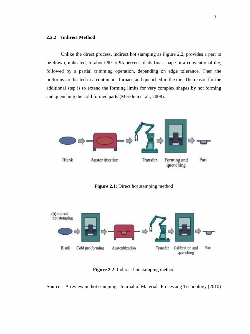
Unlike the direct process, indirect hot stamping as Figure 2.2, provides a part to
be drawn, unheated, to about 90 to 95 percent of its final shape in a conventional die,
followed by a partial trimming operation, depending on edge tolerance. Then the
preforms are heated in a continuous furnace and quenched in the die. The reason for the
additional step is to extend the forming limits for very complex shapes by hot forming
and quenching the cold formed parts (Merklein et al., 2008).
Figure 2.1: Direct hot stamping method
Figure 2.2: Indirect hot stamping method
Source : A review on hot stamping, Journal of Materials Processing Technology (2010)
8
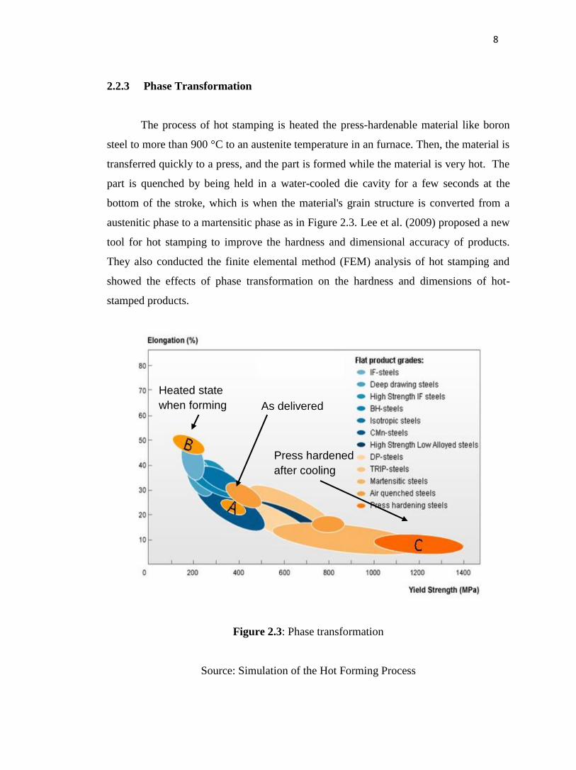
2.2.3 Phase Transformation
The process of hot stamping is heated the press-hardenable material like boron
steel to more than 900 °C to an austenite temperature in an furnace. Then, the material is
transferred quickly to a press, and the part is formed while the material is very hot. The
part is quenched by being held in a water-cooled die cavity for a few seconds at the
bottom of the stroke, which is when the material's grain structure is converted from a
austenitic phase to a martensitic phase as in Figure 2.3. Lee et al. (2009) proposed a new
tool for hot stamping to improve the hardness and dimensional accuracy of products.
They also conducted the finite elemental method (FEM) analysis of hot stamping and
showed the effects of phase transformation on the hardness and dimensions of hot-
stamped products.
Figure 2.3: Phase transformation
Source: Simulation of the Hot Forming Process
As delivered
Heated state
when forming
Press hardened
after cooling

9
2.3 TRIBOLOGY CHARACTERISTICS OF BORON STEEL 22MNB5
In the automotive industry for direct and indirect hot stamping the quenchenable,
ultra-high strength steel 22MnB5 is commonly used. Also, 22MnB5 is one of the
representative materials of ultra high strength steels. Merklein et al. (2006) describe
within the scope of paper a cold-rolled strip with a material thickness of 1.75mm
produced by Arcelor is used. The boron/manganese micro-alloyed steel, so-called
USIBOR 1500P, exhibits a ferritic-pearlitic microstructure with a hardness of 171
HV10, a yield strength of 400MPa and tensile strength of approximately 600MPa. M.
Naderi et al. (2011) also describe the same material 22MnB5 reached component
strength levels over 1500MPa at elongations of 5–8% while with MS-W 1200 strength
value of at most 1200MPa were obtained.
2.3.1 Chemical Composition
Within the scope of this paper the dog-bone specimen of 22MnB5 steel with a
thickness of 1.7mm is used. Many companies produce this grade with different trade
names such as BTR165 and Usibor 1500. As described in Nikravesh et.al’s article, the
microstructure of plates consists of 78vol.% (±5%) ferrite and 22vol.% (±5%) pearlite in
as-received condition. The chemical composition is given in Table 2.1.
Table 2.1: Chemical composition of the 22MnB5 steel.
Source: J. Min et al. / Materials Science and Engineering A 550 (2012)
Alloy
elements C Mn P S Si Al Ti B Cr
Content
(wt%)
0.221 1.211 0.019 0.003 0.258 0.0360 0.0390 0.0037 0.190
10
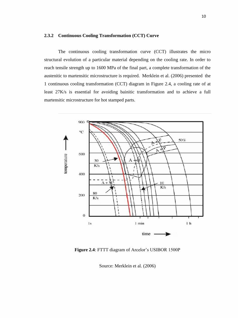
2.3.2 Continuous Cooling Transformation (CCT) Curve
The continuous cooling transformation curve (CCT) illustrates the micro
structural evolution of a particular material depending on the cooling rate. In order to
reach tensile strength up to 1600 MPa of the final part, a complete transformation of the
austenitic to martensitic microstructure is required. Merklein et al. (2006) presented the
1 continuous cooling transformation (CCT) diagram in Figure 2.4, a cooling rate of at
least 27K/s is essential for avoiding bainitic transformation and to achieve a full
martensitic microstructure for hot stamped parts.
Figure 2.4: FTTT diagram of Arcelor’s USIBOR 1500P
Source: Merklein et al. (2006)
11
2.4 TOOL IN HOT STAMPING
The complete tooling solution contains the tool steel, die design and
construction, process parameters, and dies maintenance.
Lei et al.,(2012) described the common cooling methods of hot-stamping dies
can be divided to cooling by dies themselves and cooling water system, the research of
cooling effect on hot-stamping dies is very little until now. According to Hoffmann et al.
(2007), temperature changes of hot-stamping dies were studied for many times cycles by
comparing thermal analysis and thermo-mechanical analysis, but the influences of
processing parameters on temperature distribution were not studied.
In Lei et al.,(2012) also described , the design method of hot-stamping dies and
optimization schemes of cooling system were presented. The heat transfer process was
simulated by the method of setting heat transfer coefficients on the pipe surfaces of
cooling system, but the process of turbulent flow in the pipes could not be simulated.
Also in Lei et al.,(2012) ,cooling effects of different cooling circuits in hot-stamping
dies were analyzed and the critical flow rate of cooling water was presented, but the
contact thermal resistance was not considered in the process of hot forming.
2.4.1 Die Design
Two main functions of the hot stamping die are forming the part and extracting
the heat from the blank. The tool must be able to achieve a minimum cooling rate of 27
K/s to guarantee a complete martensitic transformation. Furthermore, the heat extraction
capability of the die determines the productivity of the hot stamping line.
In design of die, thermocouple is the important to used for measured the
temperature at tools and specimen as described in journal by Naderi M. et al, (2011)
where they were used three Pt/Pt–Rh10% thermocouples for each steel. One
thermocouple was soldered to the die, 10 mm beneath the contact surface and the other
was soldered to the punch, 10 mm above the contact surface. The third thermocouple
12
was soldered to the blank 20 mm far from the edge of the blank. Every 0.2 second, the
temperature was recorded. It should be pointed that different regions of blanks do not
experience the same cooling regime because of their location. Something that results in
homogeneity of microstructure and correspondingly hardness profiles. Same with Liu et
al. (2012) described considering constraints in drilling and high cooling effectiveness
which is required that ducts should be placed as close as possible to surface of tools for
efficient cooling but at the same time sufficiently away from tool contour to avoid any
deformation of tool during hot forming process
2.4.2 Cooling Systems in Stamping Tools
The tool must be designed to cool efficiently in order to achieve maximum
cooling rate and homogeneous temperature distribution of the hot stamped part. Hence, a
cooling system needs to be integrated into the tools. The cooling system with cooling
ducts near to the tool contour is currently well known as an efficient solution. However,
the geometry of cooling ducts is restricted due to constraints in drilling and also the
ducts should be placed as near as possible for efficient cooling but sufficiently away
form the tool contour to avoid any deformation in the tool during the hot forming
process. To guarantee good characteristics of the drawn part, the whole active parts of
the tool need to be designed to cool sufficiently (Hoffmann et al. 2007). Naderi et al.
(2011) presented the cooling system was settled just inside the punch so that quenching
was started as soon as forming began.
Liu et al. (2012) described about cooling system in stamping tools is In order to
provide an effective cooling system, three tool components: punch, blank holder, and die
need to be actively cooled. The die cooling system is economical if water is used as fluid
coolant, but another important factor affecting hot stamping production cost and even
the final properties of hot stamped part is the cooling system manufacturing methods.
Employment of manufacturing method depends on geometrical shape of part which
conditions cavities of die, punch thus the arrangement of pipes of cooling system in tools
and the hot stamping production cost. A new method for designing and optimizing
cooling system is presented to improve the effectiveness of quenching during hot
13
stamping of high strength steel through thermal analysis, heat transition analysis,
together with mechanical analysis of tools used in hot stamping.
2.5 QUENCHING PROCESS
Usually when hot steel is quenched, most of the cooling happens at the surface,
as does the hardening. Different quenching media provide a variety of cooling rates.
Quenching can be done by plunging the hot steel in water. The water adjacent to the hot
steel vaporizes, and there is no direct contact of the water with the steel. This slows
down cooling until the bubbles break and allow water contact with the hot steel. As the
water contacts and boils, a great amount of heat is removed from the steel. With good
agitation, bubbles can be prevented from sticking to the steel, and thereby prevent soft
spots.
Water is a good rapid quenching medium, provided good agitation is done. When
the fastest cooling rate is required, water solutions are used as quenching media. When
suddenly quenched, the martensite is formed. This is a very strong and brittle structure.
Xing et al. (2009) study about numerical simulation of hot stamping of quenchable
boron steel where the result is the heat of quenchable steel in the furnace to austenitic
phase, then stamping in the die equipped with water-cooling system and get martensite
through quenching. After hot stamping, the tensile strength of the material is improved
by 2.5 times than that before hot stamping. However, water is corrosive with steel, and
the rapid cooling can sometimes cause distortion or cracking. Abubakre et al. (2009)
also same investigated the final stage of quenching is the most important in controlling
and reducing distortion and cracking.
Quenches are usually done to room temperature. Most medium carbon steels and
low alloy steels undergo transformation to 100% martensite at room temperature. When
the cooling rate is extremely slow then it would be mostly pearlite which is extremely
soft. However, high carbon and high alloy steels have retained austenite at room
temperature. To eliminate retained austenite, the quench temperature has to be lowered.
This quenching media produces the lowest cooling rate Abubakre et al. (2009).
14
2.6 IMPORTANT ASPECTS IN HOT STAMPING
2.6.1 Cooling Rate
Cooling rate is the rate at which heat loss occurs from the surface of an object. It
is either expressed in J/time unit or in °C/time unit. Cooling rate is an indicator to
achieve desired mechanical properties such as hardness. Bardelcik et al. (2010)
presented to investigate the effect of cooling rate on the high strain rate behavior of
hardened boron steel. In quenching tests of 22MnB5 steel samples were heated to 950
°C and quenched in three different media namely water bath at 22 °C, heated oil bath at
85 °C, and compressed air at low and high flow rates. They concluded that mechanical
properties and microstructure are strongly dependent on quenching rate, and that ideal
conditions can be achieved with the proper selection of furnace temperature and
quenching rate.
The time a material takes to cool off depends on the temperature difference
between the material and the die , the movement of the cooling at cooling channel,
shape of the die and distance of cooling channel, the material of the die, cooling flow
rate, the pressure of the cooling and the volume of the cooling. Hoffmann et al. (2007)
was study about the optimal designing of an economical cooling system in hot stamping
tools to obtain efficient cooling rate in the tool.
Merklein et al. (2006) represented further results of investigations on the thermo-
mechanical flow properties of the quenchenable, ultra high strength steel 22MnB5 in
dependency of the temperature, the strain and the cooling rate where they have been
chosen three cooling rates as parameters namely air cooling, 50 K/s and 80 K/s, in order
to detect their influence on the flow behavior.
While Nishibata et al. (2012) investigated the effect of the cooling rate on the
hardness and microstructure of the hot-stamped boron steel containing 0.2 % mass
carbon. They results showed that the upper critical cooling rate is about 30 °C/s and the
upper critical cooling rate to achieve fully lath-martensite is about 300 °C/s. They results