experimental clock calibration on a crystal-free mote-on-a
TRANSCRIPT
HAL Id: hal-02266563https://hal.inria.fr/hal-02266563
Submitted on 14 Aug 2019
HAL is a multi-disciplinary open accessarchive for the deposit and dissemination of sci-entific research documents, whether they are pub-lished or not. The documents may come fromteaching and research institutions in France orabroad, or from public or private research centers.
L’archive ouverte pluridisciplinaire HAL, estdestinée au dépôt et à la diffusion de documentsscientifiques de niveau recherche, publiés ou non,émanant des établissements d’enseignement et derecherche français ou étrangers, des laboratoirespublics ou privés.
Experimental Clock Calibration on a Crystal-FreeMote-on-a-Chip
Ioana Suciu, Filip Maksimovic, David Burnett, Osama Khan, Brad Wheeler,Arvind Sundararajan, Thomas Watteyne, Xavier Vilajosana, Kris Pister
To cite this version:Ioana Suciu, Filip Maksimovic, David Burnett, Osama Khan, Brad Wheeler, et al.. ExperimentalClock Calibration on a Crystal-Free Mote-on-a-Chip. IEEE INFOCOM - CNERT 2019 : InternationalWorkshop on Computer and Networking Experimental Research using Testbeds, Apr 2019, Paris,France. �hal-02266563�
Experimental Clock Calibrationon a Crystal-Free Mote-on-a-Chip
Ioana Suciu1, Filip Maksimovic2, David Burnett2, Osama Khan2, Brad Wheeler2,Arvind Sundararajan2, Thomas Watteyne3, Xavier Vilajosana1 4, Kris Pister2
1 Worldsensing, Spain. [email protected] University of California, Berkeley, USA. {fil,db,oukhan,brad.wheeler,arvinds,ksjp}@berkeley.edu
3 Inria, France. [email protected] Universitat Oberta de Catalunya and Worldsensing, Spain [email protected]
Abstract—The elimination of the off-chip frequency reference,typically a crystal oscillator, would bring important benefitsin terms of size, price and energy efficiency to IEEE802.15.4compliant radios and systems-on-chip. The stability of on-chiposcillators is orders of magnitude worse than that of a crystal.It is known that as the temperature changes, they can driftmore than 50ppm/◦C. This paper presents the result of anextensive experimental study. First, we propose mechanisms forcrystal-free radios to be able to track an IEEE802.15.4 joinproxy, calibrate the on-chip oscillators and maintain calibrationagainst temperature changes. Then, we implement the resultingalgorithms on a crystal-free platform and present the results ofan experimental validation. We show that our approach is ableto track a crystal-based IEEE802.15.4-compliant join proxy andmaintain the requested radio frequency stability of ±40ppm, evenwhen subject to temperature variation of 2◦C/min.
Index Terms—crystal-free radio, IEEE802.15.4, short-rangewireless, standard-compliance, clock calibration, reference fre-quency stability, low-power wireless mesh networking.
I. INTRODUCTION
IEEE802.15.4 [1] is a popular standard for short-range wire-less communication. IEEE802.15.4-compliant radios typicallyoperate in the 2.4 GHz frequency band. It is the underlyingtechnology in protocol stacks such as ZigBee or 6TiSCH,which organize a number of IEEE802.15.4-compliant devicesin a mesh network topology. These types of networks arewidely used in home automation, smart building, smart cityand industrial applications.
Manufacturers building IEEE802.15.4-compatible chipsmust ensure a radio frequency stability not exceeding ±40ppmwhile transmitting a packet [2]. Crystals are typically usedas the reference oscillators for synthesizing the radio fre-quency, and keeping time. Crystals are popular because theyprovide the necessary stability while remaining low-power. Itis common to use two crystals: a “slow” ultra low-powercrystal oscillator for time-keeping (typ. 32,768 Hz) and a“fast” and more power-hungry crystal oscillator for radiofrequency synthesis (typ. 12-48 MHz) [3]. Crystal oscillatorsare, however, off-chip elements. They contribute to the energyconsumption, size and cost of the final product, which becomessignificant at high volumes (millions of chips) [4].
To further integrate IEEE802.15.4-compliant chips, researchis being done on designing on-chip oscillators that couldreplace the off-chip (crystal) oscillators [5]–[7], aiming to
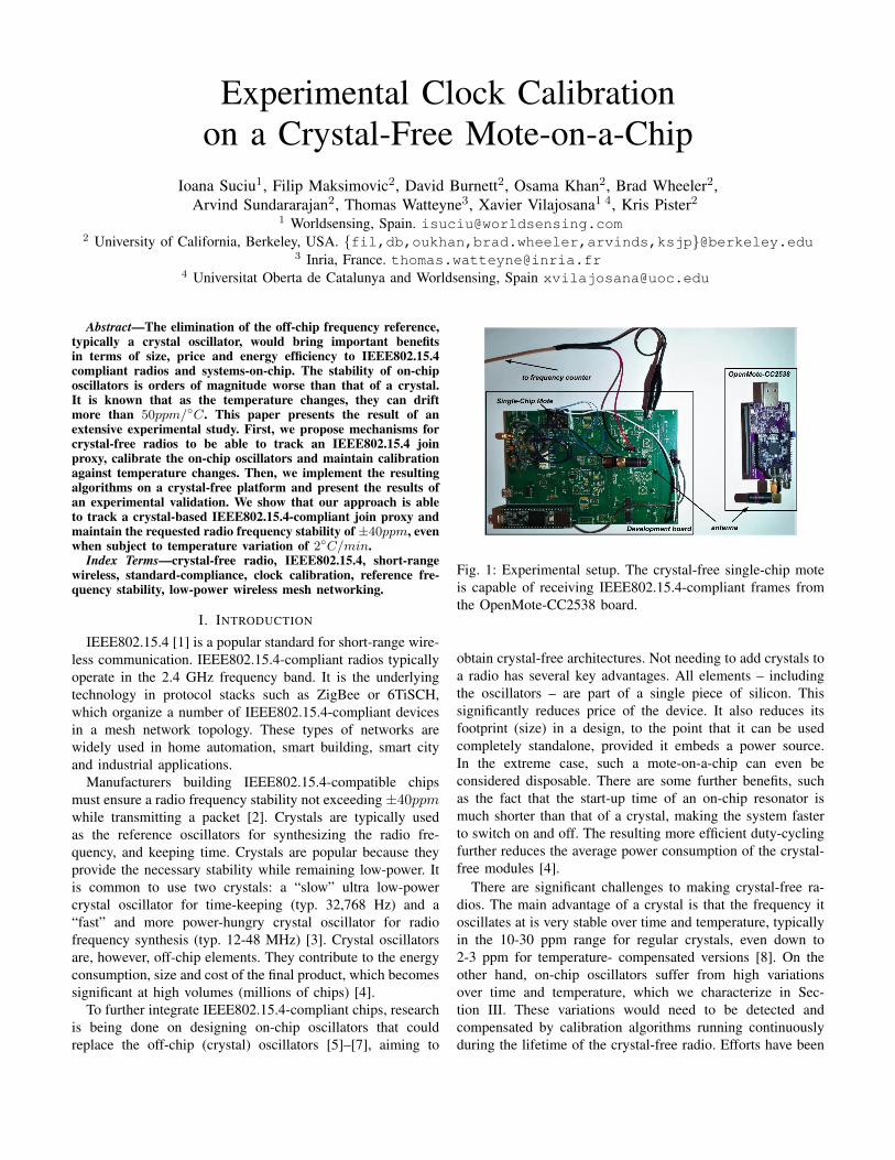
Fig. 1: Experimental setup. The crystal-free single-chip moteis capable of receiving IEEE802.15.4-compliant frames fromthe OpenMote-CC2538 board.
obtain crystal-free architectures. Not needing to add crystals toa radio has several key advantages. All elements – includingthe oscillators – are part of a single piece of silicon. Thissignificantly reduces price of the device. It also reduces itsfootprint (size) in a design, to the point that it can be usedcompletely standalone, provided it embeds a power source.In the extreme case, such a mote-on-a-chip can even beconsidered disposable. There are some further benefits, suchas the fact that the start-up time of an on-chip resonator ismuch shorter than that of a crystal, making the system fasterto switch on and off. The resulting more efficient duty-cyclingfurther reduces the average power consumption of the crystal-free modules [4].
There are significant challenges to making crystal-free ra-dios. The main advantage of a crystal is that the frequency itoscillates at is very stable over time and temperature, typicallyin the 10-30 ppm range for regular crystals, even down to2-3 ppm for temperature- compensated versions [8]. On theother hand, on-chip oscillators suffer from high variationsover time and temperature, which we characterize in Sec-tion III. These variations would need to be detected andcompensated by calibration algorithms running continuouslyduring the lifetime of the crystal-free radio. Efforts have been

made towards achieving an on-chip frequency reference ofhigher accuracy [5]–[7], but the temperature influence on theseoscillators is still too high for compliance with IEEE802.15.4,as that standard mandates a drift below 40 ppm at all times.
The contribution of this paper is two-fold. First, we de-velop an method by which a crystal-free platform with anun-calibrated on-chip oscillator tunes its radio to receiveIEEE802.15.4-compliant frames, and cope with temperaturevariations. The resulting algorithm tracks the IEEE802.15.4frames it receives and continuously fine-tunes the radio tostay within the IEEE802.15.4 oscillator specifications [2]The algorithm is generic and can be applied to any crystal-free platform. Second, we implement and test the algorithmon the “Single-Chip Mote” (SCM) [9], a crystal-free plat-form that contains a micro-controller and an ultra low-powerIEEE802.15.4-compliant radio in a single chip. We evaluatethe performance of the solution by having the Single-ChipMote communicate with an OpenMote [10], a well-knowncrystal-based IEEE802.15.4 compliant platform. From the bestof our knowledge, this paper is the first one to show a crystal-free radio successfully communicating with a crystal-basedIEEE802.15.4 compliant radio.
The remainder of this paper is organized as follows. Sec-tion II surveys related work on crystal-free radios. Section IIIcharacterizes the on-chip oscillators most relevant to this pa-per. Section IV develops the algorithm for the start-up calibra-tion of the crystal-free radio, and evaluates its performance onSCM. Section V extends the algorithm and the evaluation onmaintaining calibration over temperature. Finally, Section VIconcludes this paper.
II. RELATED WORK
Watteyne et al. did some early work with the eZ430-RF2500 platform to replace the “slow” 32 kHz crystal bythe internal oscillators of the MSP430 micro-controller onthat platform [8]. They implement an adaptive synchronizationtechnique where neighbor nodes re-synchronize to one anotherat least every 10 s. The resulting drift is approx. 100 ppm.While this work does not attempt to replace the “fast” crystalused by the radio (which is what our paper does), it does showthat getting < 40 ppm using on-chip oscillators is a challenge.
Mehta et al. explore whether it is possible to relax therequirement IEEE802.15.4 puts on maximum oscillator driftrequirements for the RF carrier frequency accuracy from± 40 ppm to ± 1000 ppm [11]. They show, by simulation,that standards-compliant narrow-band wireless communicationis still feasible with ± 1000 ppm oscillators by compensatingtheir drift using a wide bandwidth channel-select filter, ademodulator and an adaptive feedback loop in the receiver.
Wheeler et al. focus on the design parameters and theelectronic scheme of a crystal-free radio that has a driftdue to phase noise less than the ± 40 ppm specificationof IEEE802.15.4 over 13 h in a constant-temperature envi-ronment, and a drift of 95 ppm/◦C when the temperaturechanges [12]. In order to deal with temperature variations,the authors use demodulator-based feedback to allow the
receiver to track the drift of the transmitter when the trans-mitter is placed in a temperature chamber and subjected to atemperature variation of 2◦C/min. The devices used in theexperiments are composed of FPGA boards and communicateover a wire on which jitter is added to emulate the wirelessmedium. The receiver is able to track the transmitter’s signal.
Khan et al. propose a solution to calibrate the frequencyof a crystal-free radio by tracking the beacons sent by anode that has a crystal reference [13]. This work assumes thecrystal-free radio is able to receive the beacons. In order todemonstrate the feasibility of the proposal, the authors useoff the shelf OpenMote-CC2538 boards [10]. One OpenMote-CC2538 board is programmed to use its crystal and transmit.The other two OpenMote-CC2538 boards simulate a crystal-free device: RX and RC connected to an FPGA that calibratesthe RC oscillator. The authors obtain an accuracy of 70 ppmfor a 1 MHz RC oscillator.
Khan et al. extend this work by testing their approach on aFPGA implementation of the digital system of a crystal-freemote [4]. Using a wired setting, the accuracy obtained usingnetwork calibration is 47 ppm for a 25 MHz oscillator.
Our paper takes the state of the art one step further,as it presents a complete solution for initially tuning andmaintaining the tuning so a crystal-free radio is able toreceive a IEEE802.15.4-compliant frame sent by an off-the-shelf crystal-based device. To the best of our knowledge, thisis the first paper to achieve this.
III. IEEE 802.15.4 CRYSTAL-FREE RADIOCHARACTERIZATION
This section details the challenges is terms of clocking ofa crystal-free radio.
For being able to receive and/or transmit IEEE802.15.4frames, there are two important frequencies that need tobe correctly generated by any compliant-device: the radiochannel frequency (in the 2.4 GHz band) and the ”chipping”frequency (2 MHz) used to modulate/demodulate the packets.In this paper, we refer to the oscillators generating the radiochannel frequency and the 2 MHz frequency as the “RFclock” and the “chipping clock”, respectively. Link-layer leveltime synchronization between devices that communicate overIEEE802.15.4 are out of scope of this paper, and is a wellstudied topic [8].
When in receive mode (RX mode), the RF clock is theonly one that needs calibration for setting it on the chosencommunication channel. This happens because, for RX mode,the chipping clock can be recovered from the incomingIEEE802.15.4 frames by a clock and data recovery module(CDR). When the platform is in transmit mode (TX mode),the on-chip oscillator generating the chipping clock has to becalibrated along with the one generating the RF clock. Thesystem is half duplex: at any given time, the RF clock is usedeither for transmit, or for receive.
In the remainder of this section, we discuss the stabilityover time and temperature of the two oscillators that generatethe RF clock and TX mode chipping clock, respectively.
(a)
(b)
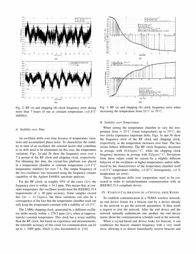
Fig. 2: RF (a) and chipping (b) clock frequency error duringmore than 7 hours of run at constant temperature (±0.3◦Cstability).
A. Stability over Time
An oscillator drifts over time because of temperature varia-tions and accumulated phase noise. To characterize the stabil-ity in time of an oscillator, the external factors that contributeto its drift need to be eliminated (in this case, the temperaturevariation). Figs. 2a and 2b show the frequency error over a7 h period of the RF clock and chipping clock, respectively.For obtaining this data, the crystal-free platform was placedin a temperature chamber at constant temperature (±0.3◦Ctemperature stability) for over 7 h. The output frequency ofthe two oscillators was measured using the frequency countercapability of the Agilent E4440A spectrum analyzer.
For the RF clock, in roughly 95% of the cases (2σ), thefrequency error is within ± 34.1 ppm. This means that, at con-stant temperature, this oscillator would meet the IEEE802.15.4requirements of ± 40 ppm accuracy. Some samples exceedthis (3σ = 51.15ppm), but these variations can also be aconsequence of the fact that the temperature chamber used canonly keep the temperature constant with a stability of ±0.3◦C.
The 2 MHz chipping clock, generated by a different oscilla-tor, drifts mostly within ± 278.5 ppm (2σ), when at (approxi-mately) constant temperature. This clock has a worse stabilitythan the RF clock, but based on experience and measurements,the tolerable accuracy of this clock for communication can beup to ± 1000 ppm, which is also documented in [14].
(a)
(b)
Fig. 3: RF (a) and chipping (b) clock frequency error whenincreasing the temperature from 25◦C to 70◦C.
B. Stability over Temperature
When setting the temperature chamber to vary the tem-perature from ≈ 25◦C (room temperature) up to 70◦C, thetwo clocks experience important drifts. Figs. 3a and 3b showthe frequency error of the RF clock and chipping clock,respectively, as the temperature increases over time. The twoclocks behave differently. The RF clock frequency decreasesin average with 48.64ppm/◦C, while the chipping clockfrequency increases in average with 355ppm/◦C. Deviationsfrom these values could be caused by a slightly differentbehavior of the oscillators at higher temperatures and/or influ-enced by the characteristics of the temperature chamber itself(±0.3◦C temperature stability, ±3.25◦C homogeneity, ±2 %temperature set error).
These significant drifts over temperature need to be cor-rected in order to initiate/maintain communication with anIEEE802.15.4 compliant device.
IV. STARTUP CALIBRATION OF A CRYSTAL-FREE RADIO
To establish communication in a TDMA wireless network,an end device listens for a beacon sent by a device alreadyin the network to get the network parameters. It then sendsa request to join the network. After the end device and thenetwork mutually authenticate one another, the end devicelearns about the communication schedule used in the network.
When a crystal-based end device looks for beacons, it cansynthesize the beacon channel frequency with a very smallerror, allowing it to almost immediately receive beacons and
(a)
(b)
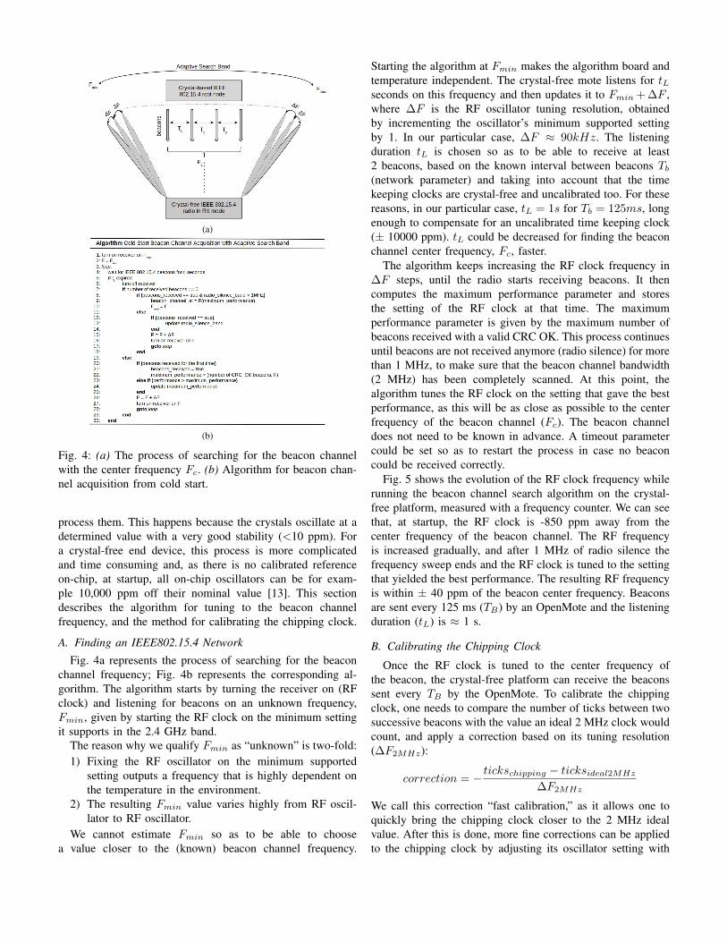
Fig. 4: (a) The process of searching for the beacon channelwith the center frequency Fc. (b) Algorithm for beacon chan-nel acquisition from cold start.
process them. This happens because the crystals oscillate at adetermined value with a very good stability (<10 ppm). Fora crystal-free end device, this process is more complicatedand time consuming and, as there is no calibrated referenceon-chip, at startup, all on-chip oscillators can be for exam-ple 10,000 ppm off their nominal value [13]. This sectiondescribes the algorithm for tuning to the beacon channelfrequency, and the method for calibrating the chipping clock.
A. Finding an IEEE802.15.4 Network
Fig. 4a represents the process of searching for the beaconchannel frequency; Fig. 4b represents the corresponding al-gorithm. The algorithm starts by turning the receiver on (RFclock) and listening for beacons on an unknown frequency,Fmin, given by starting the RF clock on the minimum settingit supports in the 2.4 GHz band.
The reason why we qualify Fmin as “unknown” is two-fold:1) Fixing the RF oscillator on the minimum supported
setting outputs a frequency that is highly dependent onthe temperature in the environment.
2) The resulting Fmin value varies highly from RF oscil-lator to RF oscillator.
We cannot estimate Fmin so as to be able to choosea value closer to the (known) beacon channel frequency.
Starting the algorithm at Fmin makes the algorithm board andtemperature independent. The crystal-free mote listens for tLseconds on this frequency and then updates it to Fmin + ∆F ,where ∆F is the RF oscillator tuning resolution, obtainedby incrementing the oscillator’s minimum supported settingby 1. In our particular case, ∆F ≈ 90kHz. The listeningduration tL is chosen so as to be able to receive at least2 beacons, based on the known interval between beacons Tb(network parameter) and taking into account that the timekeeping clocks are crystal-free and uncalibrated too. For thesereasons, in our particular case, tL = 1s for Tb = 125ms, longenough to compensate for an uncalibrated time keeping clock(± 10000 ppm). tL could be decreased for finding the beaconchannel center frequency, Fc, faster.
The algorithm keeps increasing the RF clock frequency in∆F steps, until the radio starts receiving beacons. It thencomputes the maximum performance parameter and storesthe setting of the RF clock at that time. The maximumperformance parameter is given by the maximum number ofbeacons received with a valid CRC OK. This process continuesuntil beacons are not received anymore (radio silence) for morethan 1 MHz, to make sure that the beacon channel bandwidth(2 MHz) has been completely scanned. At this point, thealgorithm tunes the RF clock on the setting that gave the bestperformance, as this will be as close as possible to the centerfrequency of the beacon channel (Fc). The beacon channeldoes not need to be known in advance. A timeout parametercould be set so as to restart the process in case no beaconcould be received correctly.
Fig. 5 shows the evolution of the RF clock frequency whilerunning the beacon channel search algorithm on the crystal-free platform, measured with a frequency counter. We can seethat, at startup, the RF clock is -850 ppm away from thecenter frequency of the beacon channel. The RF frequencyis increased gradually, and after 1 MHz of radio silence thefrequency sweep ends and the RF clock is tuned to the settingthat yielded the best performance. The resulting RF frequencyis within ± 40 ppm of the beacon center frequency. Beaconsare sent every 125 ms (TB) by an OpenMote and the listeningduration (tL) is ≈ 1 s.
B. Calibrating the Chipping Clock
Once the RF clock is tuned to the center frequency ofthe beacon, the crystal-free platform can receive the beaconssent every TB by the OpenMote. To calibrate the chippingclock, one needs to compare the number of ticks between twosuccessive beacons with the value an ideal 2 MHz clock wouldcount, and apply a correction based on its tuning resolution(∆F2MHz):
correction = − tickschipping − ticksideal2MHz
∆F2MHz
We call this correction “fast calibration,” as it allows one toquickly bring the chipping clock closer to the 2 MHz idealvalue. After this is done, more fine corrections can be appliedto the chipping clock by adjusting its oscillator setting with
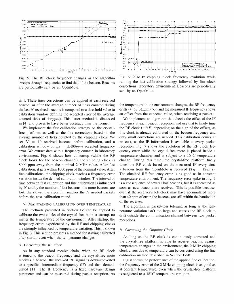
Fig. 5: The RF clock frequency changes as the algorithmsweeps through frequencies to find that of the beacon. Beaconsare periodically sent by an OpenMote.
± 1. These finer corrections can be applied at each receivedbeacon, or after the average number of ticks counted duringthe last N received beacons is compared to a threshold value (acalibration window defining the accepted error of the averagecounted ticks of ±xppm). This latter method is discussedin [4] and proves to have better accuracy than the former.
We implement the fast calibration strategy on the crystal-free platform, as well as the fine corrections based on theaverage number of ticks counted by the chipping clock. Weset N = 10 received beacons before calibration, and acalibration window of ±x = ±400ppm accepted frequencyerror. We extract data with a frequency counter, in laboratoryenvironment. Fig. 6 shows how at startup (while the RFclock looks for the beacon channel), the chipping clock is8000 ppm away from the nominal 2 MHz value. After fastcalibration, it gets within 1000 ppm of the nominal value. Afterfine calibrations, the chipping clock reaches a frequency errorvariation inside the defined calibration window. The interval oftime between fast calibration and fine calibration is influencedby N and by the number of lost beacons: the more beacons arelost, the slower the algorithm reaches the N needed packetsbefore the next calibration round.
V. MAINTAINING CALIBRATION OVER TEMPERATURE
The methods presented in Section IV can be applied tocalibrate the two clocks of the crystal-free mote at startup, nomatter the temperature of the environment. After startup, thefrequency errors experienced by the RF and chipping clocksare strongly influenced by temperature variation. This is shownin Fig. 3. This section presents a method for staying calibratedafter startup even when the temperature changes.
A. Correcting the RF clock
As in any standard receive chain, when the RF clockis tuned to the beacon frequency and the crystal-free motereceives a beacon, the received RF signal is down-convertedto a specified intermediate frequency (IF) and then demod-ulated [11]. The IF frequency is a fixed hardware designparameter and can be measured during packet reception. As
Fig. 6: 2 MHz chipping clock frequency evolution whilerunning the fast calibration strategy followed by fine clockcorrections, laboratory environment. Beacons are periodicallysent by an OpenMote.
the temperature in the environment changes, the RF frequencydrifts (≈ 48.64ppm/◦C) and the measured IF frequency showsan offset from the expected value, when receiving a packet.
We implement an algorithm that checks the offset of the IFfrequency at each beacon reception, and use that to finely tunethe RF clock (±∆F , depending on the sign of the offset), asthis clock is already calibrated on the beacon frequency andonly small corrections are needed. This calibration comes atno cost, as the IF information is available at every packetreception. Fig. 7 shows the evolution of the RF clock fre-quency error while the crystal-free mote is placed inside atemperature chamber and is subject to a 15◦C temperaturechange. During this time, the crystal-free platform finelytunes the RF clock based on the measured IF every timea beacon from the OpenMote is received (TB = 125ms).The obtained RF frequency error is as good as in constanttemperature environment. The frequency error spike in Fig. 7is a consequence of several lost beacons, but it is corrected assoon as new beacons are received. This is possible because,even if the receiver’s RF clock may have accumulated morethan 40 ppm of error, the beacons are still within the bandwidthof the receiver.
The algorithm is packet-loss tolerant, as long as the tem-perature variation isn’t too large and causes the RF clock todrift outside the communication channel between two packetreceptions.
B. Correcting the Chipping Clock
As long as the RF clock is continuously corrected andthe crystal-free platform is able to receive beacons againsttemperature changes in the environment, the 2 MHz chippingclock errors due to temperature can be corrected using the finecalibration method described in Section IV-B.
Fig. 8 shows the performance of the applied fine calibration:the frequency error of the 2 MHz chipping clock is as good asat constant temperature, even when the crystal-free platformis subjected to a 15◦C temperature variation.
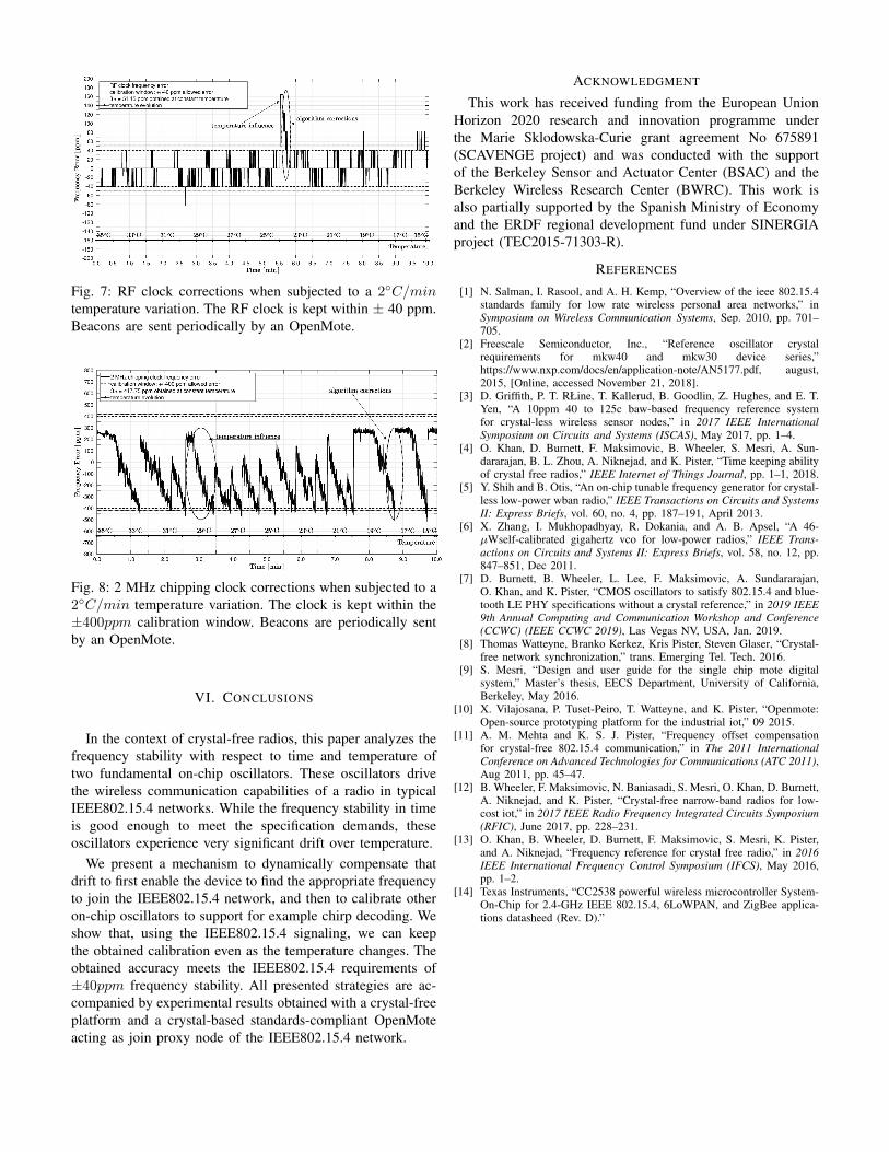
Fig. 7: RF clock corrections when subjected to a 2◦C/mintemperature variation. The RF clock is kept within ± 40 ppm.Beacons are sent periodically by an OpenMote.
Fig. 8: 2 MHz chipping clock corrections when subjected to a2◦C/min temperature variation. The clock is kept within the±400ppm calibration window. Beacons are periodically sentby an OpenMote.
VI. CONCLUSIONS
In the context of crystal-free radios, this paper analyzes thefrequency stability with respect to time and temperature oftwo fundamental on-chip oscillators. These oscillators drivethe wireless communication capabilities of a radio in typicalIEEE802.15.4 networks. While the frequency stability in timeis good enough to meet the specification demands, theseoscillators experience very significant drift over temperature.
We present a mechanism to dynamically compensate thatdrift to first enable the device to find the appropriate frequencyto join the IEEE802.15.4 network, and then to calibrate otheron-chip oscillators to support for example chirp decoding. Weshow that, using the IEEE802.15.4 signaling, we can keepthe obtained calibration even as the temperature changes. Theobtained accuracy meets the IEEE802.15.4 requirements of±40ppm frequency stability. All presented strategies are ac-companied by experimental results obtained with a crystal-freeplatform and a crystal-based standards-compliant OpenMoteacting as join proxy node of the IEEE802.15.4 network.
ACKNOWLEDGMENT
This work has received funding from the European UnionHorizon 2020 research and innovation programme underthe Marie Sklodowska-Curie grant agreement No 675891(SCAVENGE project) and was conducted with the supportof the Berkeley Sensor and Actuator Center (BSAC) and theBerkeley Wireless Research Center (BWRC). This work isalso partially supported by the Spanish Ministry of Economyand the ERDF regional development fund under SINERGIAproject (TEC2015-71303-R).
REFERENCES
[1] N. Salman, I. Rasool, and A. H. Kemp, “Overview of the ieee 802.15.4standards family for low rate wireless personal area networks,” inSymposium on Wireless Communication Systems, Sep. 2010, pp. 701–705.
[2] Freescale Semiconductor, Inc., “Reference oscillator crystalrequirements for mkw40 and mkw30 device series,”https://www.nxp.com/docs/en/application-note/AN5177.pdf, august,2015, [Online, accessed November 21, 2018].
[3] D. Griffith, P. T. RŁine, T. Kallerud, B. Goodlin, Z. Hughes, and E. T.Yen, “A 10ppm 40 to 125c baw-based frequency reference systemfor crystal-less wireless sensor nodes,” in 2017 IEEE InternationalSymposium on Circuits and Systems (ISCAS), May 2017, pp. 1–4.
[4] O. Khan, D. Burnett, F. Maksimovic, B. Wheeler, S. Mesri, A. Sun-dararajan, B. L. Zhou, A. Niknejad, and K. Pister, “Time keeping abilityof crystal free radios,” IEEE Internet of Things Journal, pp. 1–1, 2018.
[5] Y. Shih and B. Otis, “An on-chip tunable frequency generator for crystal-less low-power wban radio,” IEEE Transactions on Circuits and SystemsII: Express Briefs, vol. 60, no. 4, pp. 187–191, April 2013.
[6] X. Zhang, I. Mukhopadhyay, R. Dokania, and A. B. Apsel, “A 46-µWself-calibrated gigahertz vco for low-power radios,” IEEE Trans-actions on Circuits and Systems II: Express Briefs, vol. 58, no. 12, pp.847–851, Dec 2011.
[7] D. Burnett, B. Wheeler, L. Lee, F. Maksimovic, A. Sundararajan,O. Khan, and K. Pister, “CMOS oscillators to satisfy 802.15.4 and blue-tooth LE PHY specifications without a crystal reference,” in 2019 IEEE9th Annual Computing and Communication Workshop and Conference(CCWC) (IEEE CCWC 2019), Las Vegas NV, USA, Jan. 2019.
[8] Thomas Watteyne, Branko Kerkez, Kris Pister, Steven Glaser, “Crystal-free network synchronization,” trans. Emerging Tel. Tech. 2016.
[9] S. Mesri, “Design and user guide for the single chip mote digitalsystem,” Master’s thesis, EECS Department, University of California,Berkeley, May 2016.
[10] X. Vilajosana, P. Tuset-Peiro, T. Watteyne, and K. Pister, “Openmote:Open-source prototyping platform for the industrial iot,” 09 2015.
[11] A. M. Mehta and K. S. J. Pister, “Frequency offset compensationfor crystal-free 802.15.4 communication,” in The 2011 InternationalConference on Advanced Technologies for Communications (ATC 2011),Aug 2011, pp. 45–47.
[12] B. Wheeler, F. Maksimovic, N. Baniasadi, S. Mesri, O. Khan, D. Burnett,A. Niknejad, and K. Pister, “Crystal-free narrow-band radios for low-cost iot,” in 2017 IEEE Radio Frequency Integrated Circuits Symposium(RFIC), June 2017, pp. 228–231.
[13] O. Khan, B. Wheeler, D. Burnett, F. Maksimovic, S. Mesri, K. Pister,and A. Niknejad, “Frequency reference for crystal free radio,” in 2016IEEE International Frequency Control Symposium (IFCS), May 2016,pp. 1–2.
[14] Texas Instruments, “CC2538 powerful wireless microcontroller System-On-Chip for 2.4-GHz IEEE 802.15.4, 6LoWPAN, and ZigBee applica-tions datasheed (Rev. D).”