experimental evaluation of the markl fatigue methods and asme piping stress … · 2018-09-21 ·...
TRANSCRIPT
Experimental Evaluation of the Markl Fatigue Methods and ASME Piping Stress
Intensification Factors
2008 ASME PVP ConferenceChicago, IL
July 28, 2008
Tony PaulinPaulin Research Group
Houston, TX
Chris HinnantPaulin Research Group
Houston, TX
Introduction

3
Introduction
• 12 new experimental piping fatigue tests have been completed to help examine the Markl fatigue methods.
• 10 Girth Butt Welds
• 2 Unreinforced Tees
• 600 butt welds were gathered and compared to the Markl girth mean butt weld fatigue curve.
• Although Markl’s data points are within scatter band of the reported data, Markl’s mean fatigue curve does not agree with the same experimental data.
• A new mean girth butt weld is proposed for use with SIF testing (B31.J) and the ASME piping codes.

44
Why Perform New Tests?
• There aren’t many low cycle girth butt weld tests.
• Some tests indicate that Markl’s slope and mean curve may not be representative of larger data sets.
• Paulin Research Group’s analytical and experimental experience has been that SIF’s are often too low – difficult to match Markl’s results.
• Markl’s curve does not follow the expected trends for fatigue of weldments. Slope coefficient of 5.0 vs. 3.0
• Several active ASME Technology projects are reevaluating the current SIF’s and flexibility factors
• Piping codes are being applied beyond simple thermal expansion cases.
• Understanding how and why components fail is becoming more important.

Background

66
Markl Testing and Stress Intensification Factors
• Markl & George began fatigue testing piping components in the late 1940’s.
• The majority of experiments used 4” SCH 40 piping.
• End result was a mean fatigue curve for girth butt welded pipe and Stress Intensification Factors (SIF’s) for piping components.
• SIF rules are base-lined to an SIF of 1.0 which is for girth butt welds.
• “Girth butt weld” really pertains most directly to girth butt welds joining weld neck flanges to pipes. In some Markl tests, tapered forgings were used for girth butt weld tests.
• Markl’s work is the primary basis of ASME B31 piping rules.

77
What is an SIF?
• A Stress Intensification Factor (SIF) is the average nominal bending stress to cause failure in a girth butt weld divided by the nominal stress to cause failure in the component being tested.
f
f
N
f
fN
SfNksi
SIFi
NksiSfi20.0
20.0
490
490−
−
⋅==
⋅=⋅

88
Markl’s Mean Girth Butt Weld Curve
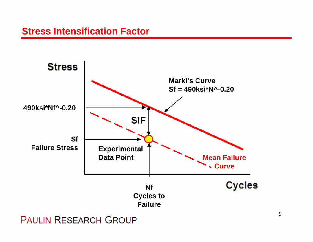
9
Stress Intensification Factor
SfFailure Stress
NfCycles to
Failure
Markl’s CurveSf = 490ksi*N^-0.20
SIF
Experimental Data Point
490ksi*Nf^-0.20
Mean FailureCurve

Description of Tests
1111
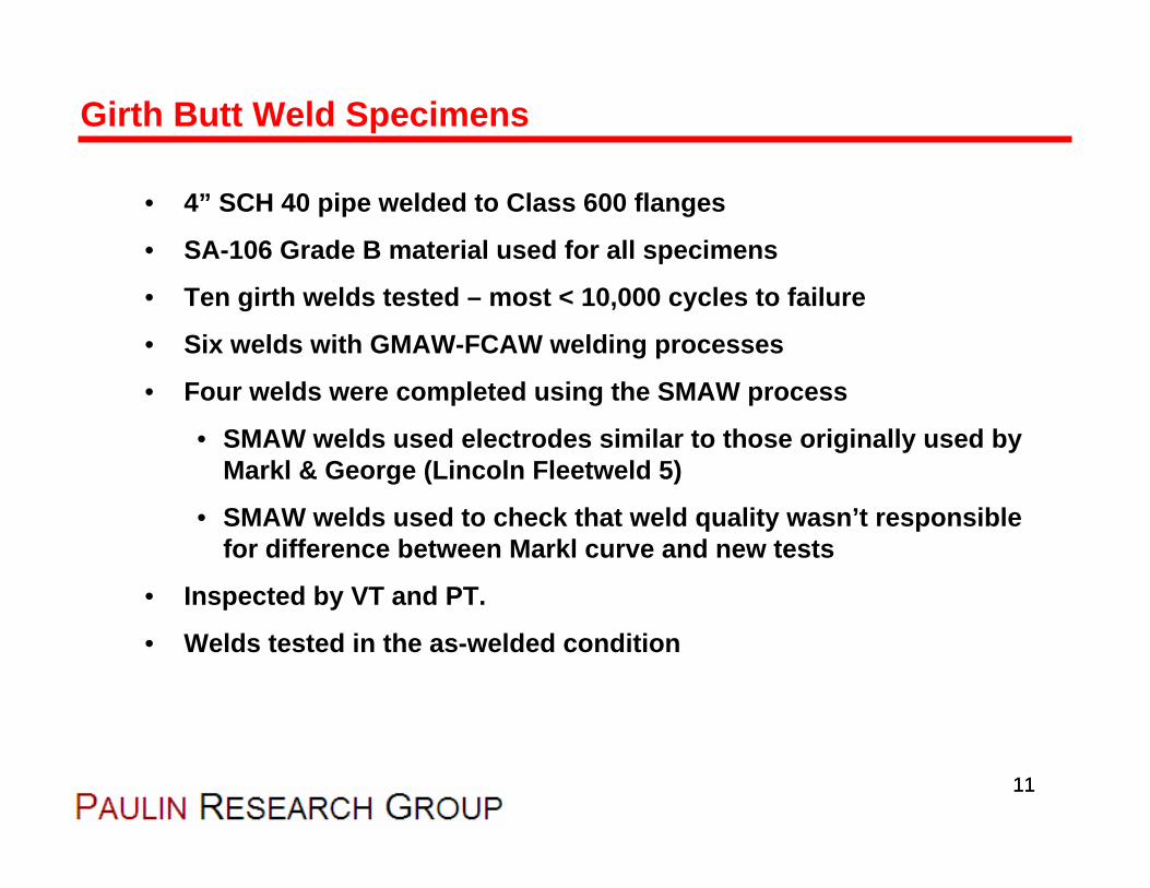
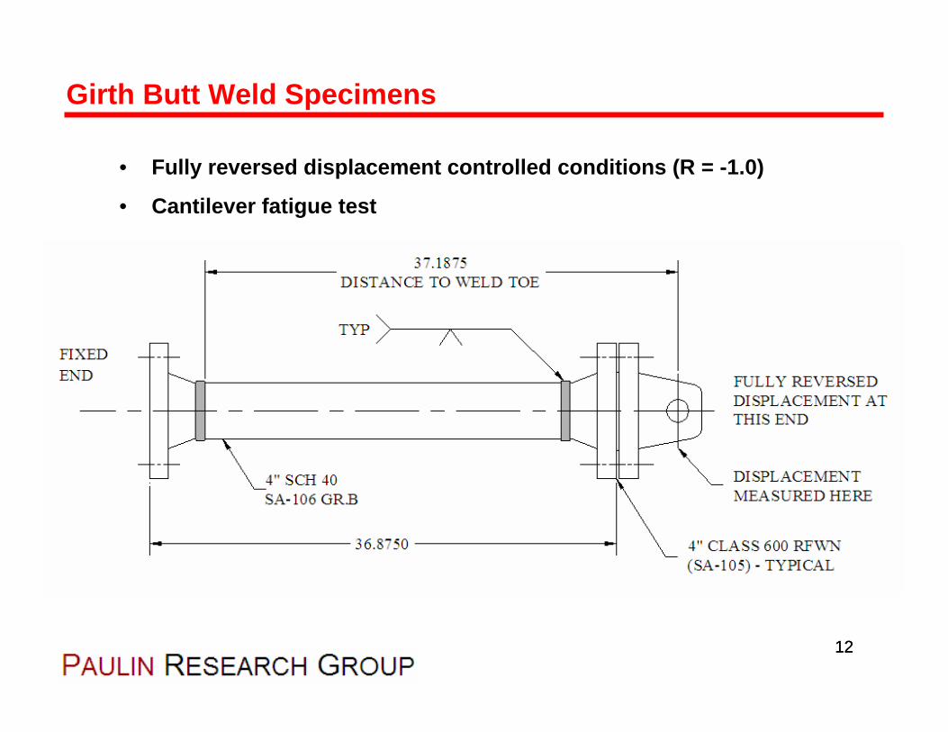
Girth Butt Weld Specimens
• 4” SCH 40 pipe welded to Class 600 flanges
• SA-106 Grade B material used for all specimens
• Ten girth welds tested – most < 10,000 cycles to failure
• Six welds with GMAW-FCAW welding processes
• Four welds were completed using the SMAW process
• SMAW welds used electrodes similar to those originally used by Markl & George (Lincoln Fleetweld 5)
• SMAW welds used to check that weld quality wasn’t responsible for difference between Markl curve and new tests
• Inspected by VT and PT.
• Welds tested in the as-welded condition
1212
Girth Butt Weld Specimens
• Fully reversed displacement controlled conditions (R = -1.0)
• Cantilever fatigue test

1313
Girth Butt Weld Specimens
SMAW Weld
GMAW-FCAW Weld

1414
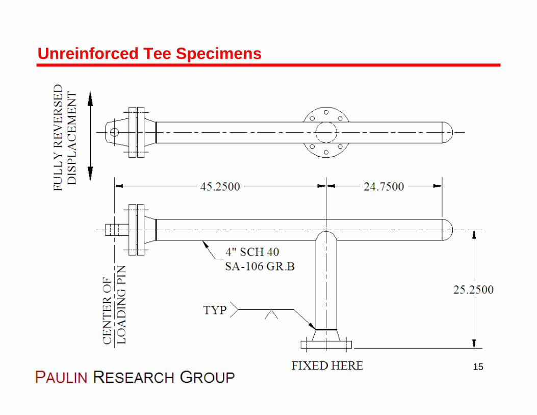
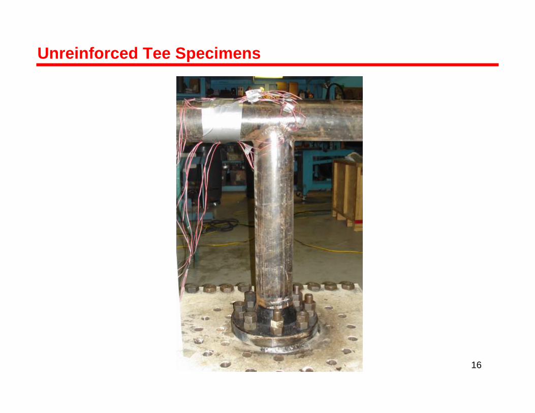
Unreinforced Tee Specimens
• Two size-on-size UFT’s tested
• 4” SCH 40 pipe, SA-106 Grade B
• GTAW welding process
• Out-of-plane loading through the header pipe
• Fully reversed displacement controlled conditions
• Inspected by VT and PT.
• Welds tested in the as-welded condition.
Unreinforced Tee Specimens
15
Unreinforced Tee Specimens
16

Unreinforced Tee Specimens

Experimental Procedure

General “Markl” Procedure:
• Step 1 – Apply strain gauges
• Step 2 – Mount specimen to fatigue test machine
• Step 3 – Fill specimens with room temperature water
• Step 4 – Generate a load-deflection curve
• Step 5 – Select a displacement range for fatigue test
• Step 6 – Run test until visible leakage occurs
• Step 7 – Record the cycles to failure, stress is based on extrapolation of the elastic stiffness from Step #4
Experimental Procedure
19
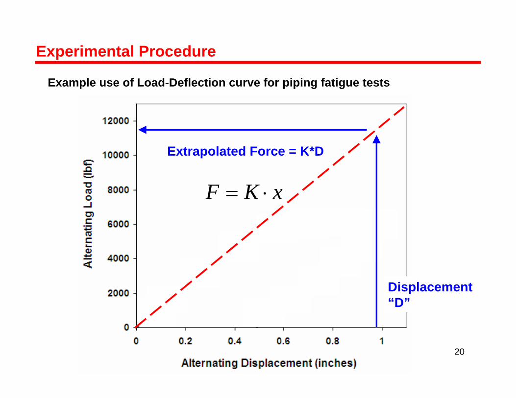
Example use of Load-Deflection curve for piping fatigue tests
Experimental Procedure
xKF ⋅=
Displacement“D”
Extrapolated Force = K*D
20
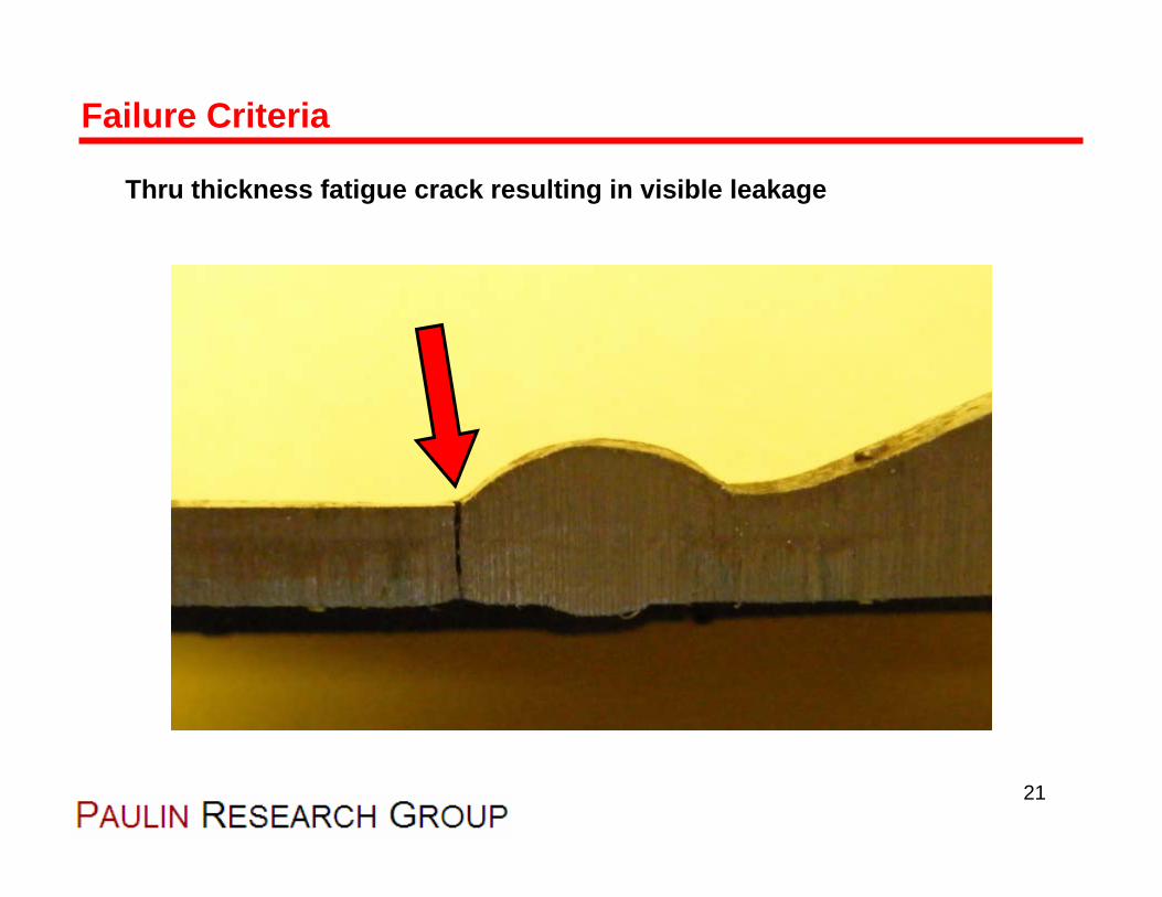
Thru thickness fatigue crack resulting in visible leakage
Failure Criteria
21

Experimental Results

• Results of 10 new girth butt weld tests are shown below.
• Standard deviation of Log(N) with best-fit curve 0.082
• Standard deviation about Markl’s mean curve is 0.78
Girth Butt Weld Tests
314.01465 −⋅= fN NksiSff
23
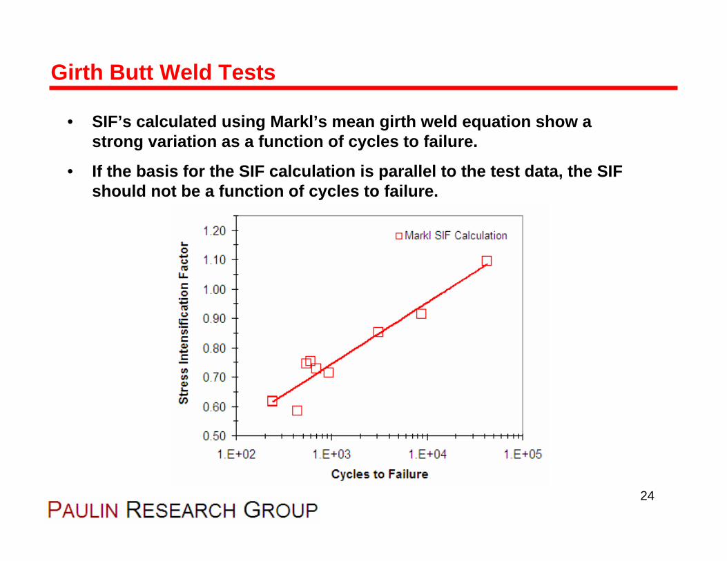
• SIF’s calculated using Markl’s mean girth weld equation show a strong variation as a function of cycles to failure.
• If the basis for the SIF calculation is parallel to the test data, the SIF should not be a function of cycles to failure.
Girth Butt Weld Tests
24
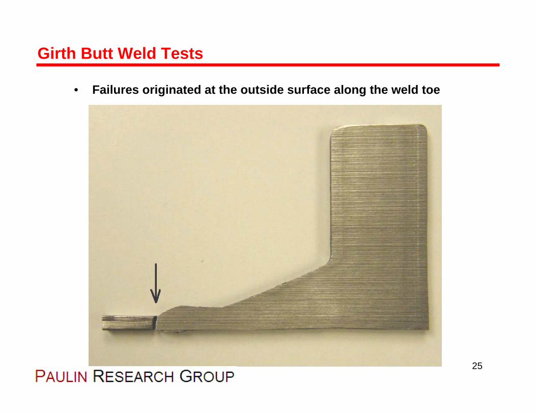
• Failures originated at the outside surface along the weld toe
Girth Butt Weld Tests
25
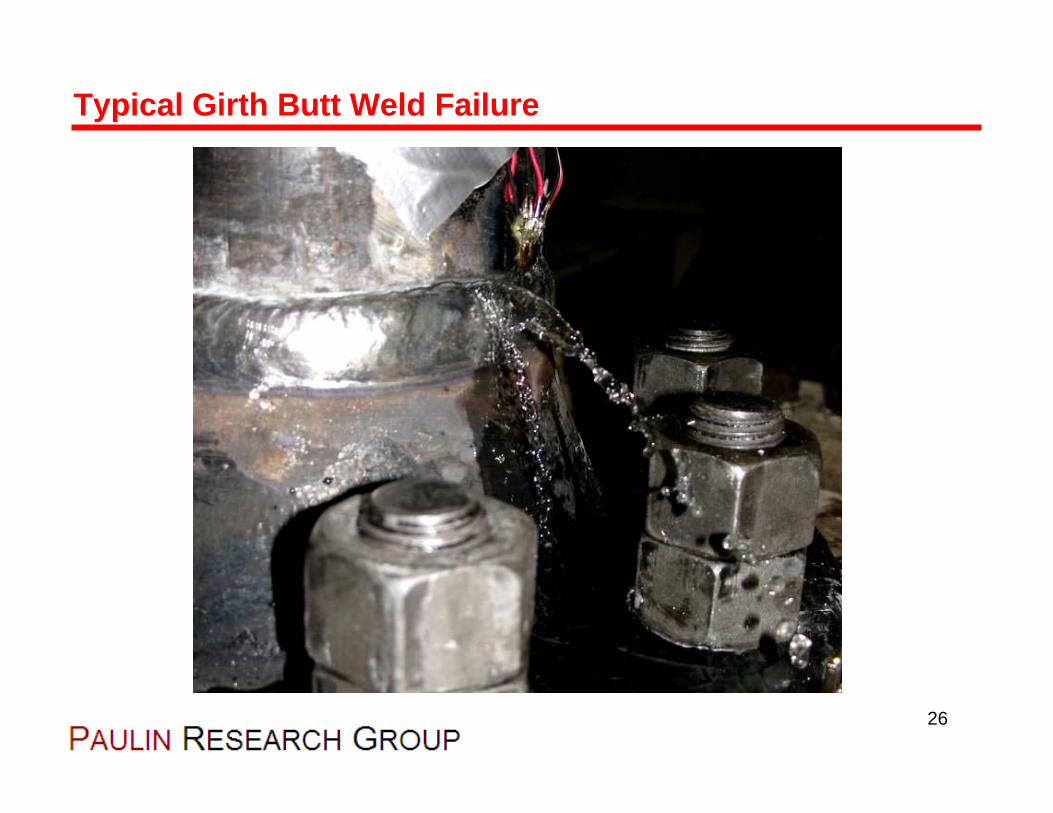
Typical Girth Butt Weld Failure
26

• Results of 2 new girth butt weld tests shown below.
• Three failures sites in the two samples.
• Best-Fit equation slope is close to m = -1/3 (not -1/5 like Markl)
Unreinforced Tee Results
295.0387 −⋅= fN NksiSff
27
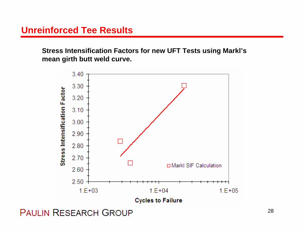
Stress Intensification Factors for new UFT Tests using Markl’s mean girth butt weld curve.
Unreinforced Tee Results
28
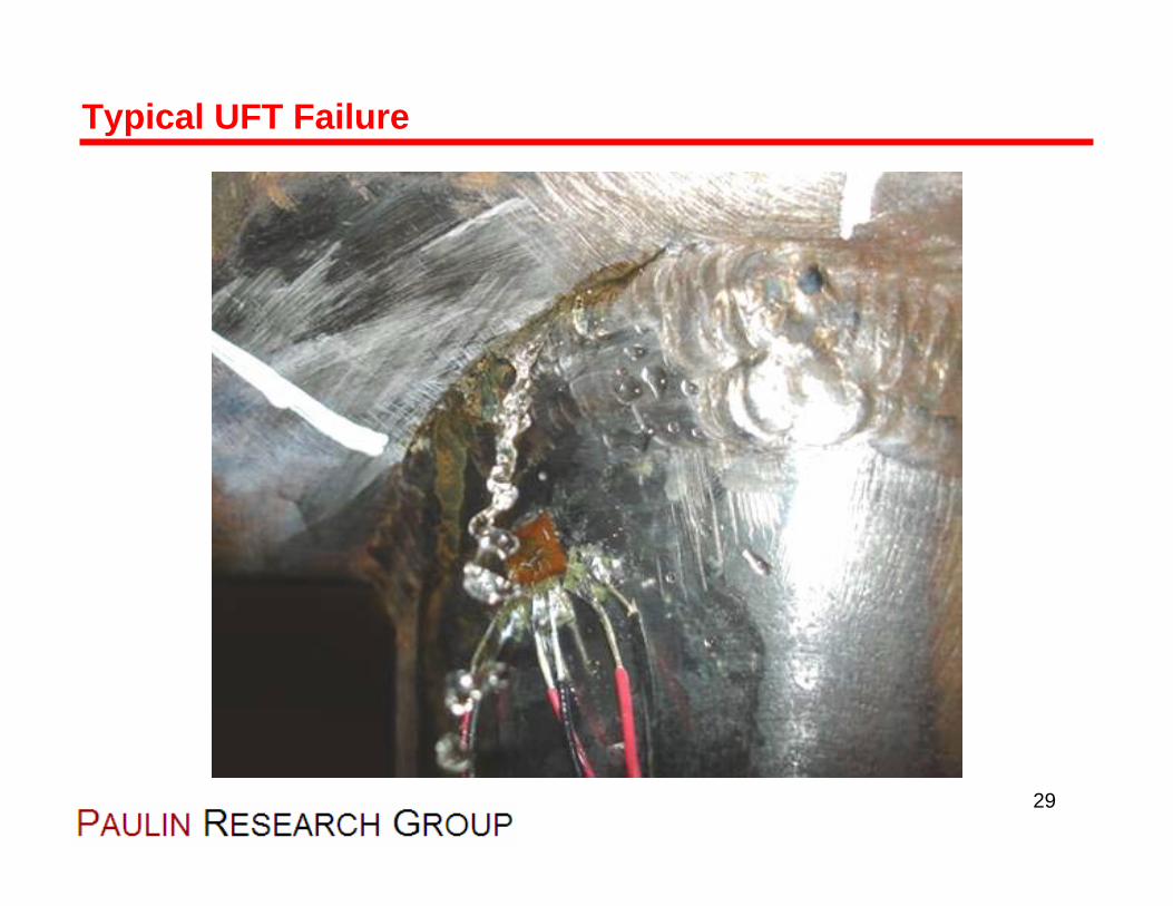
Typical UFT Failure
29

Validation of Resultsand Markl Comparisons
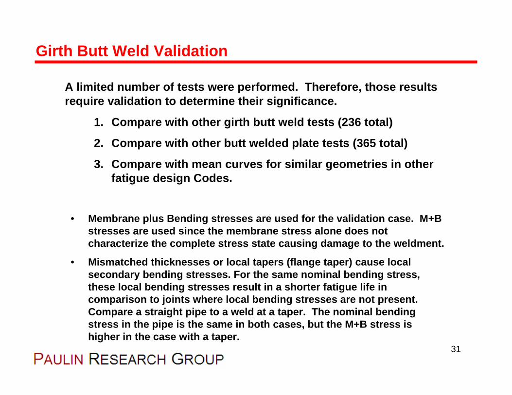
A limited number of tests were performed. Therefore, those results require validation to determine their significance.
1. Compare with other girth butt weld tests (236 total)
2. Compare with other butt welded plate tests (365 total)
3. Compare with mean curves for similar geometries in other fatigue design Codes.
• Membrane plus Bending stresses are used for the validation case. M+B stresses are used since the membrane stress alone does not characterize the complete stress state causing damage to the weldment.
• Mismatched thicknesses or local tapers (flange taper) cause local secondary bending stresses. For the same nominal bending stress,these local bending stresses result in a shorter fatigue life incomparison to joints where local bending stresses are not present. Compare a straight pipe to a weld at a taper. The nominal bending stress in the pipe is the same in both cases, but the M+B stress is higher in the case with a taper.
Girth Butt Weld Validation
31

• PRG girth butt weld test validation with 236 girth butt welds
• Note difference between the mean data curve and Markl’s curve.
Girth Butt Validation
32

• 236 girth welds and 365 flat plate butt welds
• Poor comparison between “Best Fit” curve and Markl’s curve.
Girth Butt Validation
33
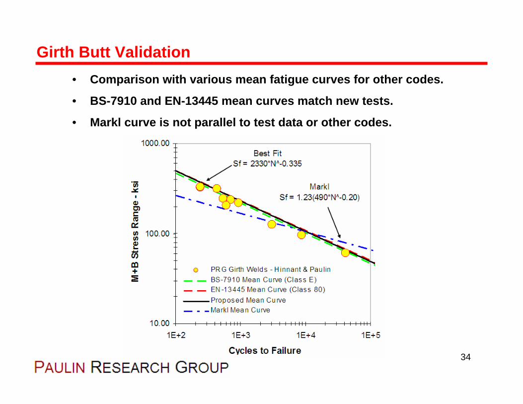
• Comparison with various mean fatigue curves for other codes.
• BS-7910 and EN-13445 mean curves match new tests.
• Markl curve is not parallel to test data or other codes.
Girth Butt Validation
34
Summary of girth butt weld validation:
1. Approximately 600 butt weld tests have been reviewed.
2. New PRG tests match existing pipe and plate data.
3. Markl’s mean curve differs from the mean curve for the data collected in this work.
4. Markl’s mean curve is not parallel to the data collected.
Girth Butt Weld Validation
35
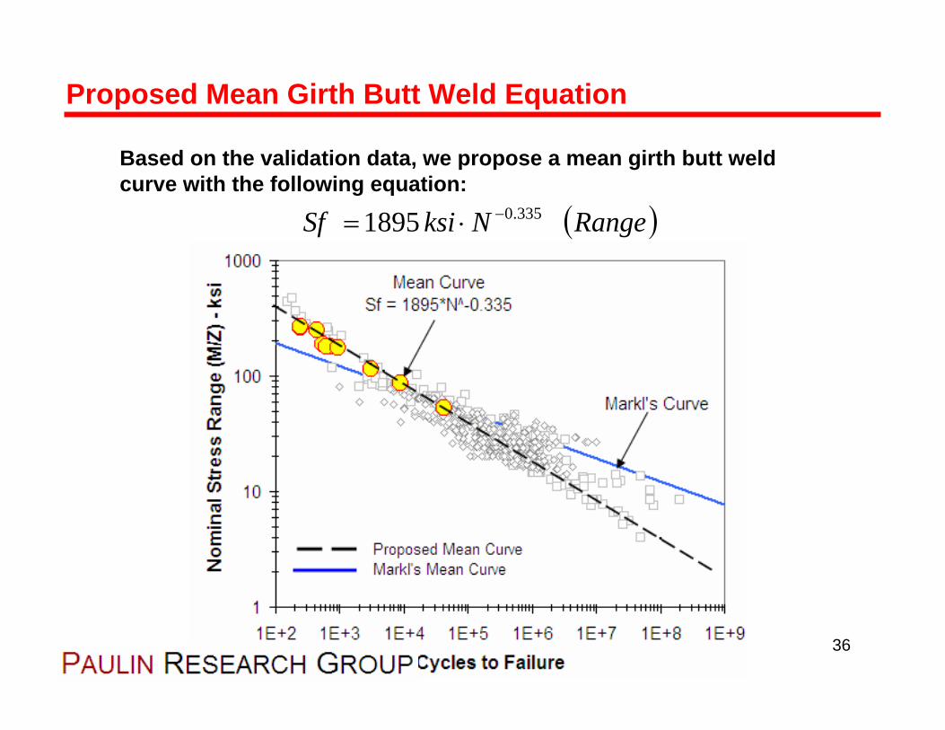
Based on the validation data, we propose a mean girth butt weld curve with the following equation:
Proposed Mean Girth Butt Weld Equation
( )RangeNksiSf 335.01895 −⋅=
36

Significance to the Piping Codes

• Markl’s mean butt weld curve is not consistent with the new PRG tests, other data collected, and other fatigue codes.
• Potential issues affect any piping rules that rely on the Markl methodologies (for example B31.1, B31.3, Section III Class 2/3)
• Most apparent discrepancy is the difference in slope coefficients
• Markl’s equation uses -1/5, test data suggests -1/3
There are three areas of importance relative to the Codes:
1. An errant slope produces a variable design margin.
2. Low cycle SIF testing with Markl’s curve may lead to inappropriately low SIF’s. This is important for B31.J.
3. High cycle design with rules derived from Markl’s tests may over predict the fatigue life.
Significance to the Piping Codes
38

• ASME B31.3 provides a design margin of 1.63 on stress for the fatigue life of girth butt welds (11.5 on cycles)
• Data here shows that the B31.3 margin of 1.63 is maintained up to 22,790 cycles.
• Above 22,790 cycles, the design margin relative to the presented data continues to decrease.
• At 850,000 cycles the B31.3 design life equals the mean life to failure for the data presented here (design margin is zero).
• Above 850,000 cycles, the B31.3 Code permits design lives in excess of the average failure life.
Item #1 - Variable Design Margin
For basic conditions with carbon steel material:
39

• SIF’s may be underestimated by using Markl’s mean curve in the low cycle regime.
Item #2 - Errors in Low Cycle SIF Testing
Markl Mean Curve
MarklSIF
RecommendedMean Curve
TestData
Actual SIF
40

Using a low cycle SIF may result in reduced margins at higher design lives.
Item #2 - Errors in Low Cycle SIF Testing
Markl Mean Curve
Markl Predicted Fatigue Life
MarklSIF
RecommendedMean Curve
SIFErrorActual Fatigue
Behavior
41

• Is this trend only for butt welds? NO –all geometries are affected.
• UFT tests by PRG and Wais & Rodabaugh suggest that Markl’s slope does not fit the experimental data.
Item #2 - Errors in Low Cycle SIF Testing
42
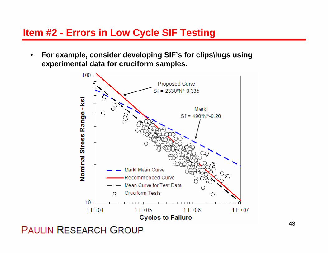
• For example, consider developing SIF’s for clips\lugs using experimental data for cruciform samples.
Item #2 - Errors in Low Cycle SIF Testing
43
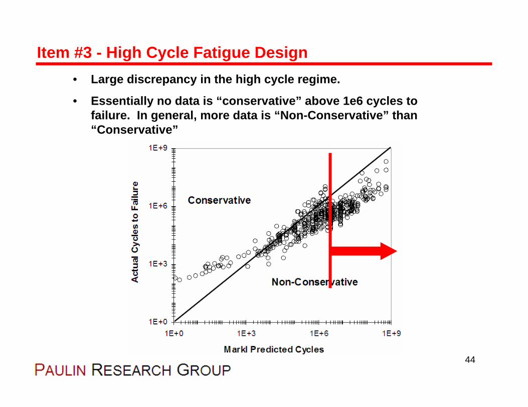
• Large discrepancy in the high cycle regime.
• Essentially no data is “conservative” above 1e6 cycles to failure. In general, more data is “Non-Conservative” than “Conservative”
Item #3 - High Cycle Fatigue Design
44

Recommendations

• Consider use of recommended girth butt weld equation for SIF development and possible implementation into the B31 Codes
• The proposed equation has several benefits in light of the test data reviewed to date:
1. Increased low cycle design lives
2. Better correlation with other fatigue methods and state-of-the-art today
3. Improved predictions in the high cycle regime
4. More consistent design margins for all portions of the SN design curves
5. An opportunity for alignment to harmonize with other ASME fatigue methods.
Recommendations
46
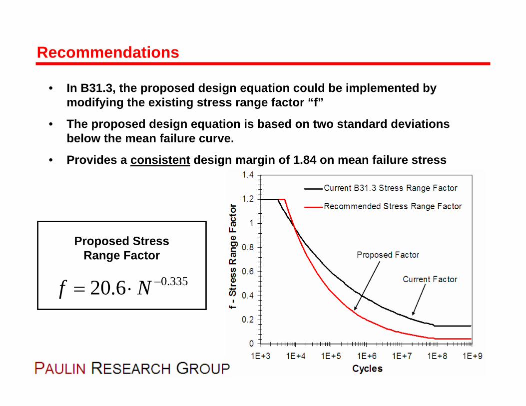
• In B31.3, the proposed design equation could be implemented by modifying the existing stress range factor “f”
• The proposed design equation is based on two standard deviationsbelow the mean failure curve.
• Provides a consistent design margin of 1.84 on mean failure stress
Recommendations
335.06.20 −⋅= Nf
Proposed Stress Range Factor
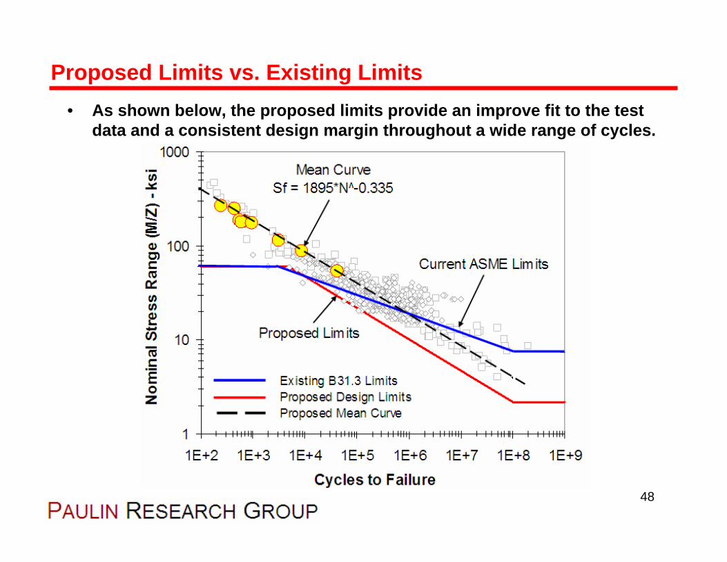
• As shown below, the proposed limits provide an improve fit to the test data and a consistent design margin throughout a wide range of cycles.
Proposed Limits vs. Existing Limits
48
• New test results presented here suggest amendments to the Markl piping methods are warranted. These conclusions are supported by other experimental references and design codes.
• The fatigue curve slope used by Markl’s equations does not match results for existing test data.
• Current B31.3 code rules do not provide a consistent design margin for the reported tests. Above 850,000 cycles, the rules may allow design lives in excess of the mean failure life.
• Markl’s mean girth weld equation may lead to inconsistent SIF’s. SIF’s tested within the low cycle regime may be under predicted.
• High cycle fatigue strength appears to be over estimated by Markl’s curve.
• A new girth butt weld equation has been proposed that fits a large population of data and agrees with other fatigue design methods.
Conclusions
49

This presentation will be available for download at:
www.paulin.com
This presentation will be repeated in an upcoming Webinar (online presentation). Check our website for details and other
technical papers, downloads, etc.
Thanks for your time!