experimental investigation of an active twist model rotor ... · the blades is changing and the...
TRANSCRIPT
ABSTRACTSmart materials that are directly embedded in the rotor blade structure are an attractive concept for active blade control. A promising approach is the use of anisotropic piezoelectric strain actuators embedded in the rotor blade skin. Especially in Europe and the US this concept has been intensively investigated over the past years. A major drawback of all configurations studied so far is the high operation voltage of up to 2,000V of state of the art piezoelectric actuators. Within the Green Rotorcraft Project of the European Joint Technology Initiative Clean Sky, a new approach with a low voltage piezoelectric actuation system is investigated to demonstrate the feasibility of this technology.
A first major step in this direction was completed by conducting a centrifugal test with a model rotor blade. The objective of the centrifugal test was to demonstrate the performance of the actuation system and the structural concept under centrifugal loads by showing that the expected twist deformation can be achieved at the nominal rotation speed and different actuation frequencies.
It was demonstrated that the new actuation system is capable of operating under representative centrifugal loads. In comparison to state-of-the-art actuators (operation voltage 500V to +1500V) the new actuation system (operation voltage −20V to 120V) exhibits higher active twist perfor-mance per active area.
The AeronAuTicAl JournAl December 2015 Volume 119 no 1222 1499
Paper No. 4367. Manuscript received 7 February 2015, revised version received 7 May 2015, accepted 24 July 2015.This is an adapted version of a paper first presented at 40th The European Rotorcraft Forum
hosted by the Royal Aeronautical Society in Southampton, UK, September 2014.
Experimental investigation of an active twist model rotor blade with a low voltage actuation system P. Wierach [email protected] S. Opitz and S. KalowInstitute of Composite Structures and Adaptive Systems German Aerospace Centre (DLR) Braunschweig Germany

1500 The AeronAuTicAl JournAl December 2015
NOMENCLATUREAFC active fibre compositeAMR active material rotorATR active twist rotorBVI blade vortex interactionCSJU Clean Sky Joint UndertakingCTE coefficient of thermal expansion [1/K]d31, d33 piezoelectric charge constants [m/V]DLR German Aerospace CenterGRC green rotor craftICP integrated circuit piezoelectric sensorLED light-emitting diodeMFC macro fibre compositeMIT Massachusetts Institute of TechnologyNACA National Advisory Committee for AeronauticsNASA National Aeronautics and Space AdministrationPZT lead zirconium titanaterev revolution RPM rotations per minute
1.0 INTRODUCTIONThe superposition of flight speed and the rotational speed of the main rotor leads to asymmetric flow conditions between the advancing and retreating side. This asymmetric the flow condition in the rotor disk grows with increasing flight speed. At the advancing side, the flow reaches transonic and critical velocities resulting in local shock waves which are a major source of noise in high-speed forward flight. At the retreating side flow, separation and stall occur. Flow separation and shock waves are highly dynamic in nature, which induces vibrations.
In low speed flight and descent flight, rotor noise and vibration are mainly caused by blade vortex interactions (BVI). In contrast to fixed-wing aircraft, for which tip vortices are moving downstream away from the wing, those created by helicopters remain in the vicinity of the rotor for several revolutions. This causes multiple blade vortex interactions when rotor blades encounter previously generated tip vortices or pass them very closely. Consequently, the velocity field around the blades is changing and the altered angle of attack generates unsteady airloads on the blades, which generate noise and vibration.
A reduction of noise and vibration is most effective when the disturbing forces are attenuated at their source, e.g. by individual control of the blades. A promising approach is the use of anisotropic piezoelectric strain actuators embedded in the rotor blade structure, capable of generating a direct twist deformation of the rotor blade. In comparison to approaches using flaps, which generate an aerodynamic moment to deform the blade, the complexity of the actuation system is rather low. Since no moving parts are involved there is no friction and wear. This is of special importance in a helicopter environment with high centrifugal forces. The same applies for the fact that no heavy mechanical components have to be installed inside the blade causing high loads on the rotor blade structure. Additionally, the active twist concept guarantees a very smooth blade surface whereas flaps have distinct edges, which additional vortices and sources for noise and vibration.
WierAch et al experimenTAl inVesTigATion of An AcTiVe TWisT moDel roTor blADe ... 1501
2.0 STATE OF THE ART IN ACTIVE TWIST BLADESThe first active twist rotors using piezoceramic materials to actuate the blade were presented by Chen and Chopra from the University of Maryland. From 1993 to 1996 they built and hover tested a series of 1/8th Froude scaled model rotors. The rotor blade skins incorporated piezoceramic plates using the transversal piezoelectric d31-effect(1). They achieved twist angles of 0.3° in a hover test.
In 1995 a team joining scientists from Boeing, Penn State University, and MIT started research in the field of active rotors. After proving the concept with a 1/16th Froude scale model rotor, they investigated the capability of active twist of two 1/6th Mach scale rotors (active material rotor AMR). At the time it was not clear whether the direct generation of structural twist or twist generation via flaps was favorable, so the first phase of this project included the design, manufac-turing, and testing of both design principles. At the beginning of the project, the active twist concept was rated as the high risk approach whereas the flap design was considered to have low risk. This direct comparison by the same team of engineers developing both concepts side-by-side pointed out many advantages of the active twist concept. Because of the encouraging results obtained, the active twist concept was applied to a modern planform and airfoil rotor blade. The active twist blades were actuated by interdigitated piezo fibre composites integrated in the spar of the rotor blade and achieved active twist angles of 2.8° in a hover test (2).
In 1999, 2000 and 2002 a joint venture between NASA, Army, and MIT built and tested an active twist rotor (ATR) with a structural design similar to the Boeing model rotor. This rotor was conceived for testing in a heavy gas medium, in the NASA Langley Transonic Dynamics Tunnel. This rotor is so far the only one that has been wind-tunnel tested under forward flight conditions. The twist was generated via active fibre composite piezoelectric actuators embedded into the rotor blade spar(3-5).
In 2004, Boeing investigated the possibility of scaling the results of the Mach-scaled rotor to a full-scale rotor blade. The main focus of this investigation was on production and manufacturing approaches concerning the incorporation of the piezoelectric actuators, and the development of a robust and reliable wiring, to provide the necessary power to the actuators. A 1.8m CH-47D blade section with 24 layers of active fibre composites embedded in the spar laminate was built and successfully tested in a non-rotating environment. It was shown that a full-scale active twist blade with a meaningful actuation capability and acceptable natural frequencies can be built within the weight limit of a passive blade(6).
Motivated by these promising results and the potential benefits, the German Aerospace Centre (DLR) started to work on active twist blades with improvements in actuation technology and alternative structural concepts to bring this technology a step forward(7-9). First experiments to demonstrate the performance of an active twist model rotor blade under centrifugal loads showed an active twist angle of about 4°(10). Several generations of active twist blades with different planforms and airfoils have been built and successfully tested(11,12). Up to now all blades used state of the art high voltage actuation technology. The purpose of the present work is to prove the feasibility of a new low voltage actuation system for active twist rotor blades.
3.0 ACTUATION TECHNOLOGYActuators and sensors based on smart materials are essential components of active rotor systems. As an integral part of the rotor blade structure, the smart material components must be capable of carrying structural loads, as well. Due to several advantages both technical and practical, piezoceramic materials are most commonly used as smart materials for active rotor systems. On
1502 The AeronAuTicAl JournAl December 2015
the technical side, the ability to operate at high frequencies and the high stiffness of the material (typical 60GPa) is important. Additionally it is relatively easy to actuate the material by means of a simple electrical field. The ‘practical’ reasons are primarily the availability and the reliable quality of the material. Piezoceramic materials are produced on an industrial level, and a growing number of manufactures offer different types and shapes. Also, the price is quite moderate in comparison to more exotic materials. The primary disadvantage of piezoceramic materials is their inherent brittleness. Whereas it is no problem to apply high compressive loads, tensile loads must be avoided at all times. Therefore, the processing and structural integration of this sensitive material must be done very carefully to avoid damages.
An appropriate solution for this problem is the use of so called ‘piezo composites’(13). Piezo composites are a combination of piezoceramic materials and ductile polymers, which form a robust and easy to use actuator and/or sensor. The actuator/sensor susceptibility to damage is significantly reduced by this measure. By properly arranging the piezoceramic material, the properties of the composite (e.g., stiffness or damping) can be specifically adjusted. Components like electrodes, electrical contacts, or insulators can also be embedded into the composite. Generally the embedding is done at the curing temperature of the polymer (typical 120-180°C). Because of the different coefficients of thermal expansion (CTE) of the polymer in comparison to the piezoceramic material and due to the shrinking of the polymer during curing, the piezo material is provided with a beneficial mechanical pre-compression. This pre-compression allows applying (limited) tensile loads to the actuator during operation.
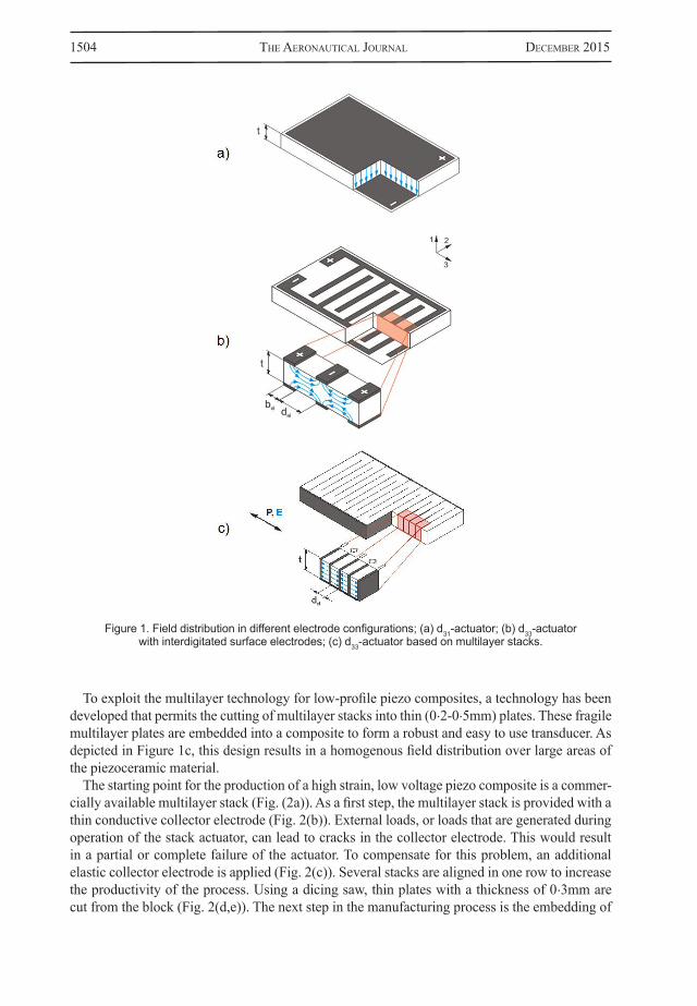
In adaptive structures only the longitudinal (d33-effect) and the transversal (d31-effect) effect are used for technically relevant piezo composites. The arrangement of the electrodes determines which effect will be used. The simplest configuration can be realized by using the d31 effect. In this case, the in plane contraction of the piezoceramic material (i.e., Poisson’s ratio effect) is used when a positive electrical field is applied in a direction normal to the thickness of the piezoce-ramic plate. Thus, the piezoceramic plate is provided with very thin layers of conductive material (a few µm) to build uniform surface electrodes. The electrical field is generated homogenously between these electrodes (Fig.1(a)). The thickness of the piezoceramic plate defines the distance between the upper and lower electrode and therefore the voltage that is needed to generate a certain electrical field. With a usual plate thickness of 0.2mm a voltage of 200V is necessary to generate an electrical field of 1kV/mm.
Up to three times higher deformations can be achieved with the d33-effect. In this case, the electrical field and the effective deformation are in the same direction. Applying a positive field will result in an expansion of the piezoceramic device in the direction of the field and a contraction perpendicular to this direction. The challenge is the generation of an in-plane electrical field. A feasible technical solution is the use of interdigitated electrodes. In this configuration, the electrodes are made of two comb-like electrodes with opposite polarity, which are applied on the surface of the piezoceramic material. The electrical field is generated between the fingers of the electrode and penetrates the piezoceramic material. Due to this special design, the electrical fields are not very homogenous (Fig. 1(b)). This has a direct impact on the minimum electrode distance and hence on the operating voltage. If the distance between the electrode fingers is too small in comparison to the thickness of the piezoceramic material, the electrical field cannot sufficiently penetrate the piezoceramic material and the efficiency of the actuator is reduced. Additionally, the areas directly below the electrode fingers do not contribute to the actuation strain. If the electrode distance is reduced, the number of electrode fingers increases, as does the ‘dead’ area below the electrodes. This can only partly be compensated by using very thin electrode fingers. Besides technical limitations in producing very thin electrode fingers, such a configuration will also cause very

WierAch et al experimenTAl inVesTigATion of An AcTiVe TWisT moDel roTor blADe ... 1503
high electrical field gradients in the vicinity of the electrodes. These high gradients lead to high mechanical loads in the piezoceramic material, resulting in an impact on lifetime and durability. A suitable electrode distance for a piezoceramic device with a thickness of 0.2mm is between 0.5-1mm. In this case, without considering the field inhomogeneity, a voltage of 500-1,000V is necessary to generate an electrical field of 1kV/mm.
For piezo composites with interdigitated electrodes, fibre like architectures that are referred to as active fibre composites (AFC) turned out to be advantageous in comparison to monolithic designs(14). Cracks caused by the inhomogeneity of the electrical field will propagate through monolithic plates; however, these cracks are stopped at each interface between the polymer and the piezoceramic fibre. Besides this, fibre-based actuators allow a directed actuation what is an advantage particularly for active twist rotor blades. A negative aspect of fibres with a circular cross section, as with the AFC actuators, is that there is only a very small contact area between the electrode fingers and the piezoceramic fibre. Thus the penetration of the electrical field is minimal, which results in even higher operation voltages and less performance. An improvement is the usage of fibres with rectangular cross sections to reduce the dielectric loss(15).
An essential drawback of fibre based composites is the very labour intensive manufacturing process. Early actuator systems, like the AFC, required handwork to place many single fibres close to one another. This causes quality problems resulting in deviations of the actuator characteristics. Also, the production and the following sintering process of PZT fibres are very cost intensive. An alternative manufacturing process uses commercially available PZT-wafers that are cut into ribbons(16). In this case the wafer is placed on a tacky film and cut with a wafer saw that is commonly used in the production of silicon-based integrated circuits. With this automated process, the rectangular fibres or ribbons are aligned exactly in parallel. This type of piezocomposite is called the macro fibre composite (MFC) and is commercialised by Smart Materials Co-operation (17).
In many applications, it is a requirement to significantly reduce the operating voltage of the piezoelectric actuators without reducing the active strain produced. The use of high voltages in technical systems is sometimes associated with some serious drawbacks. Besides more stringent safety regulations, there are insulation issues, sparking, and high voltage electronic components are usually more expensive. Also the acceptance of the user community is sometimes lacking. The desire to reduce the operating voltage of piezoelectric actuators led to the development of multilayer stack actuators. Conventional stack actuators are made of piezoceramic plates, which are glued together in a stacking sequence. To contact the electrodes, sheets of copper are also incorporated within the glue layer. The drawback of this design is the decreasing stiffness of the actuator with increasing length (or increasing number of glue layers). Also, the operating voltage cannot be reduced significantly because this would mean a reduction of the piezoceramic plate thickness, hence an increased number of plates with even more glue layers. Also the manufacturing and handling of individual thin plates is difficult. In the manufacturing process of multilayer stacks, the electrodes are incorporated during the sintering process as very thin layers (few µm). The stack itself is a monolithic block with integrated electrode layers. Therefore the influence of the electrodes on stiffness and performance is very low. This allows a reduction of the distance between the electrodes, which leads to a significantly reduced operating voltage. Standard multilayer stack actuators are operated with a maximum voltage between 120-160V, achieving active strains up to 1,800µm/m. Recent developments in automotive industry lead to the usage of multilayer stacks in fuel injection systems. Due to the mass production, a reduction in price and an improvement in quality and reliability of multilayer stacks have been observed. Encouraged by this progress, a concept has been developed to utilise multilayer stack actuators for a new type of low profile piezo composite actuator(18-20).
1504 The AeronAuTicAl JournAl December 2015
To exploit the multilayer technology for low-profile piezo composites, a technology has been developed that permits the cutting of multilayer stacks into thin (0.2-0.5mm) plates. These fragile multilayer plates are embedded into a composite to form a robust and easy to use transducer. As depicted in Figure 1c, this design results in a homogenous field distribution over large areas of the piezoceramic material.
The starting point for the production of a high strain, low voltage piezo composite is a commer-cially available multilayer stack (Fig. (2a)). As a first step, the multilayer stack is provided with a thin conductive collector electrode (Fig. 2(b)). External loads, or loads that are generated during operation of the stack actuator, can lead to cracks in the collector electrode. This would result in a partial or complete failure of the actuator. To compensate for this problem, an additional elastic collector electrode is applied (Fig. 2(c)). Several stacks are aligned in one row to increase the productivity of the process. Using a dicing saw, thin plates with a thickness of 0.3mm are cut from the block (Fig. 2(d,e)). The next step in the manufacturing process is the embedding of
Figure 1. Field distribution in different electrode configurations; (a) d31-actuator; (b) d33-actuator with interdigitated surface electrodes; (c) d33-actuator based on multilayer stacks.

WierAch et al experimenTAl inVesTigATion of An AcTiVe TWisT moDel roTor blADe ... 1505
the brittle and sensitive multilayer plate in a polymer to form the actual composite (Fig. 2(f)). Because the dimensions of the multilayer plates are limited, an array of plates can be arranged in a single composite to enlarge the active area. To increase the productivity of the process, several composites are manufactured at once and separated afterwards.
A typical strain-voltage curve of a multilayer piezo composite is plotted in Fig. 3. With an electrode distance of 53µm and a maximum voltage of 120V, a maximum electrical field of 2.26kV/
Figure 2. Principle manufacturing steps to produce a low voltage high strain piezocomposite actuator; (a) multilayer stack; (b) collector electrode; (c) flexible collector electrode; (d) dicing; (e) multilayer plate;
(f) packaging.
Figure 3. Exemplary strain-voltage curve of a multilayer piezocomposite.
1506 The AeronAuTicAl JournAl December 2015
mm was applied. All measurements were made applying a quasi-static excitation of 0.1Hz with a triangle wave form. The average active free strain that was measured with an operation voltage of 120V was 1,285µm/m. In comparison to state of the art d33-piezocomposites with interdigitated surface electrodes, which need voltages of up to 1,500V or even 2,000V to achieve same active strain levels, this actuator has demonstrated that it is possible to drastically reduce the operation voltage of d33-piezocomposites without a loss in strain performance.
It should be pointed out that the amount of electrical power required to operate the low voltage actuators is not significantly lower in comparison to high voltage MFC actuators. Since the capacity is increasing with a reduction of the electrode distance the necessary current is also increasing accordingly.
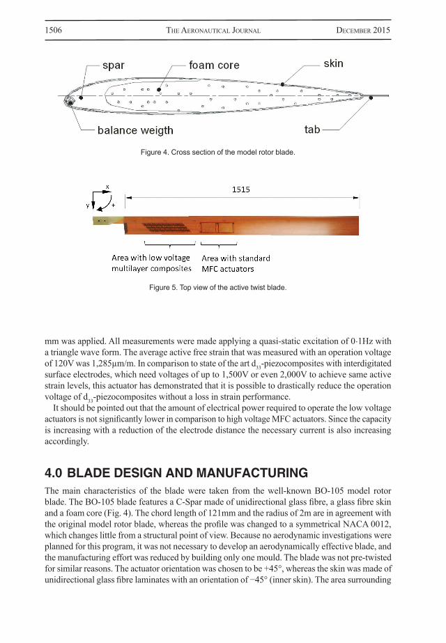
4.0 BLADE DESIGN AND MANUFACTURINGThe main characteristics of the blade were taken from the well-known BO-105 model rotor blade. The BO-105 blade features a C-Spar made of unidirectional glass fibre, a glass fibre skin and a foam core (Fig. 4). The chord length of 121mm and the radius of 2m are in agreement with the original model rotor blade, whereas the profile was changed to a symmetrical NACA 0012, which changes little from a structural point of view. Because no aerodynamic investigations were planned for this program, it was not necessary to develop an aerodynamically effective blade, and the manufacturing effort was reduced by building only one mould. The blade was not pre-twisted for similar reasons. The actuator orientation was chosen to be +45°, whereas the skin was made of unidirectional glass fibre laminates with an orientation of −45° (inner skin). The area surrounding
Figure 4. Cross section of the model rotor blade.
Figure 5. Top view of the active twist blade.

WierAch et al experimenTAl inVesTigATion of An AcTiVe TWisT moDel roTor blADe ... 1507
the actuators was provided with additional unidirectional glass fibre layers in a +45° direction in order to carry the loads of the actuators and to decrease the change in stiffness in the transition region between the skin and actuators. The anisotropy of the skin allows the actuators to work in a relatively soft direction (approximately perpendicular to the fibres in the inner skin), whereas the complete blade still maintains its torsional stiffness by the shear stiffness perpendicular to the actuators.
The manufacturing process of the upper and lower blade skin started with the placement of the actuators into the mould followed by the glass fibre prepreg. Accordingly, the strain gauge instru-mentation and the complete wiring were positioned onto the uncured prepreg. In the next step, the lay-up was placed in a vacuum bag and cured in an autoclave at a temperature of 120°C and a pressure of 6 bars. Because actuation and instrumentation are entirely integrated into the rotor blade skins, it was possible to keep the internal design similar to that of conventional passive blades. The spar and the foam core were machined to the desired shape using pre-cured unidirectional glass fibre laminates and foam blocks, respectively. Balancing weights made of tungsten 40mm long rods were added into the nose of the spar using a cold setting epoxy. Finally, the upper and lower skin, the spar, and the foam core were bonded together with an adhesive film and cured at 120°C.
To keep the costs of the experiment to a minimum, only a small section of the blade was equipped with 25 multilayer actuators on each side. To compare the new actuators with a conventional approach, two standard 45° macro fibre composite (MFC) actuators were placed on each side of the blade (Fig. 5). The designs of the two actuators are depicted in Fig. 6. In this configuration, the low-voltage multilayer actuators covered an active surface of 0.0104m² and the MFC actuators covered an active surface of 0.0194m². Each of the multilayer actuators consists of three individual multilayer plates with a length of 18mm, a width of 5mm, and a thickness of 0.3mm. At the ends of each multilayer plate there is a passive ceramic area reducing its effective active area to 69.17mm². This is due to the design of the available multilayer stack actuators from which the plates were cut. As a result the multilayer actuator shown in Fig. 1 has a total active area of 207.51mm². Because of the interconnections between the multilayer plates and the insulating edges, the overall area of the actuator adds up to 627.75mm². By using larger multilayer stacks it is possible to improve the area ratio between active and passive material. This is primarily an issue of the available actuators
Figure 6. (a) Low voltage multilayer actuators operating at −20V to +100V; (b) High voltage MFC actuators operating at −500V to 1,000V(17).

1508 The AeronAuTicAl JournAl December 2015
for this study and not a principle limit of the technology. Therefore it is a reasonable approach to compare the active surface areas of the different actuator types.
A detailed view of the multilayer actuators integrated into the blade skin is shown in Fig. 7.
5.0 EXPERIMENTAL TEST SETUPThe objective of the test was to demonstrate the performance of the actuation system and the structural concept under centrifugal loads by showing that the expected twist deformation can be achieved at the nominal rotation speed and different actuation frequencies. For this purpose, a test rig was installed at the DLR rotor tower in Braunschweig (Fig. 8).
The test rig is driven by a 30kW DC shunt-wound motor. A balancing weight is mounted on the opposite side to balance the blade. The direction of rotation is clockwise. To reduce the mechanical complexity, the pitch links have been removed. Data transfer is realized by 24 slip rings and an
Figure 7. Detailed view of the multilayer actuators integrated into the blade skin.
Figure 8. Blade mounted in the test rig.

WierAch et al experimenTAl inVesTigATion of An AcTiVe TWisT moDel roTor blADe ... 1509
additional telemetry system with 12 channels for strain gauge measurements (full bridge or half bridge) and four ICP channels for acceleration sensors. Four specially designed high voltage slip rings transfer the required electrical power to the actuators in the blade. The actuators were driven with power amplifiers capable of producing a peak to peak voltage of ±2,000V and a maximum current of 400mA. A camera, installed in the rotor tower, allows a permanent monitoring of the experiment from the control room.
To measure the active twist angle an optical measurement system was installed. The system consists of two LEDs attached at the leading- and trailing edge of the rotor blade tip and a stationary high speed camera system. By properly triggering the camera the twist movement of the blade can be visualized by the two light dots of the LEDs. In comparison to a system that needs a powerful stroboscope light capable of sufficiently illuminate the blade tip, this solution is easier and facili-tates the analysis of the blade tip motion. Because the LEDs appear as clearly distinguishable points, a Matlab image processing tool box was used to automatically determine the twist angle.
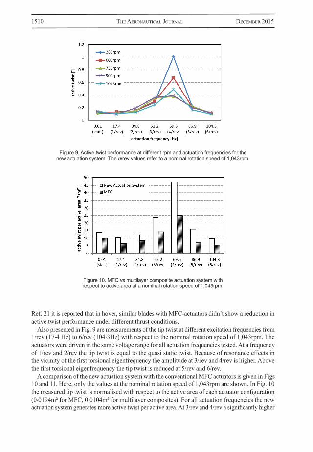
6.0 TEST RESULTSFor the centrifugal tests, a comprehensive test matrix (Table 1) was derived beginning with the measurement of the static peak¬ to peak twist displacement with increasing rotation speed starting from 280rpm up to the nominal rotation speed of 1,043rpm (109rad/s; 17.35Hz). All measurements were made using the optical measurement system. The actuators were driven within a voltage range of −500V to +1,000V for the MFC actuators and −20V to +100V for the multilayer composites with a quasi-static excitation of 0.15Hz. Due to limitations of the test rig, the pitch of the blade was set to 0°.
As shown in Fig. 9, the tip produced by the new actuation system when actuated at a quasi-static frequency of 0.01Hz is nearly the same across all rotor speeds tested. This measurement confirms that the actuation system is capable of generating sufficient twist under centrifugal loads and that there is no performance decrease in comparison to the nonrotating case. Because the test rig didn’t allow a pitch variation it was not possible to investigate the effect of higher angles-of-attack. In
Table 1Text matrix for centrifugal test
RPMFreq. 280 600 750 900 1,0430.01 Hz(stat.) 34.8 Hz(2/rev) 52.2(3/rev) 69.5 Hz(4/rev) 86.9 Hz(5/rev) 104.3 Hz(6/rev)
A:Macro fibre composite (MFC)
Operation voltage: −500 to +1,000V
B:New actuation system
Multilayer composite actuatorOperation voltage: −20 to +120V
1510 The AeronAuTicAl JournAl December 2015
Ref. 21 it is reported that in hover, similar blades with MFC-actuators didn’t show a reduction in active twist performance under different thrust conditions.
Also presented in Fig. 9 are measurements of the tip twist at different excitation frequencies from 1/rev (17.4 Hz) to 6/rev (104.3Hz) with respect to the nominal rotation speed of 1,043rpm. The actuators were driven in the same voltage range for all actuation frequencies tested. At a frequency of 1/rev and 2/rev the tip twist is equal to the quasi static twist. Because of resonance effects in the vicinity of the first torsional eigenfrequency the amplitude at 3/rev and 4/rev is higher. Above the first torsional eigenfrequency the tip twist is reduced at 5/rev and 6/rev.
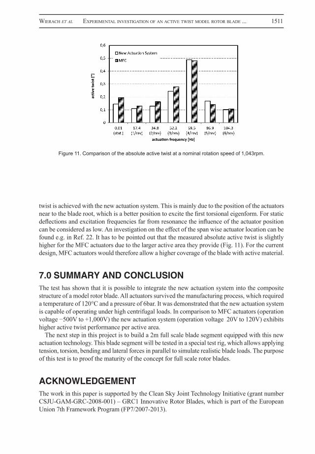
A comparison of the new actuation system with the conventional MFC actuators is given in Figs 10 and 11. Here, only the values at the nominal rotation speed of 1,043rpm are shown. In Fig. 10 the measured tip twist is normalised with respect to the active area of each actuator configuration (0.0194m² for MFC, 0.0104m² for multilayer composites). For all actuation frequencies the new actuation system generates more active twist per active area. At 3/rev and 4/rev a significantly higher
Figure 9. Active twist performance at different rpm and actuation frequencies for the new actuation system. The n/rev values refer to a nominal rotation speed of 1,043rpm.
Figure 10. MFC vs multilayer composite actuation system with respect to active area at a nominal rotation speed of 1,043rpm.
WierAch et al experimenTAl inVesTigATion of An AcTiVe TWisT moDel roTor blADe ... 1511
twist is achieved with the new actuation system. This is mainly due to the position of the actuators near to the blade root, which is a better position to excite the first torsional eigenform. For static deflections and excitation frequencies far from resonance the influence of the actuator position can be considered as low. An investigation on the effect of the span wise actuator location can be found e.g. in Ref. 22. It has to be pointed out that the measured absolute active twist is slightly higher for the MFC actuators due to the larger active area they provide (Fig. 11). For the current design, MFC actuators would therefore allow a higher coverage of the blade with active material.
7.0 SUMMARY AND CONCLUSIONThe test has shown that it is possible to integrate the new actuation system into the composite structure of a model rotor blade. All actuators survived the manufacturing process, which required a temperature of 120°C and a pressure of 6bar. It was demonstrated that the new actuation system is capable of operating under high centrifugal loads. In comparison to MFC actuators (operation voltage −500V to +1,000V) the new actuation system (operation voltage 20V to 120V) exhibits higher active twist performance per active area.
The next step in this project is to build a 2m full scale blade segment equipped with this new actuation technology. This blade segment will be tested in a special test rig, which allows applying tension, torsion, bending and lateral forces in parallel to simulate realistic blade loads. The purpose of this test is to proof the maturity of the concept for full scale rotor blades.
ACKNOWLEDGEMENTThe work in this paper is supported by the Clean Sky Joint Technology Initiative (grant number CSJU-GAM-GRC-2008-001) – GRC1 Innovative Rotor Blades, which is part of the European Union 7th Framework Program (FP7/2007-2013).
Figure 11. Comparison of the absolute active twist at a nominal rotation speed of 1,043rpm.
1512 The AeronAuTicAl JournAl December 2015
REFERENCES1. choprA, I. Status of application of smart structures technology to rotorcraft systems, J American
Helicopter Soc, 2000, 45, (4), pp 228–252.2. DerhAm, r., Weems, D.b., mATheW, m.b. and bussom, r.C. The design evolution of an active materials
rotor, 2001, American Helicopter Society.3. Shin, s., cesnik, c.e.s. and hAll, s.r. Closed-loop control test of the NASA/ARMY/MIT active twist
rotor for vibration reduction, 59th AHS Annual Forum, 6-8 May 2003, Phoenix, AZ, USA.4. Wilbur, m.l., YeAger, W.T., Wilkie, W.k., cesnik, c.e.s. and shin, s. Hover testing of the NASA/
ARMY/MIT active twist rotor prototype blade, 2000, American Helicopter Society.5. Wilbur, m.l., mirick, p.h., YeAger, W.T., lAngsTone, c.l., cesnik, c.e.s. and shin, s. Vibratory
loads reduction testing of the NASA/ARMY/MIT active twist rotor, 2001, American Helicopter Society, Washington, DC, USA
6. Weems, D.b., AnDerson, D.m., mATheW, b.m. and bussom, r.c. A large-scale active-twist rotor, 60th AHS Annual Forum, 7-10 June 2004, Baltimore, MD, USA.
7. riemenschneiDer, J., WierAch, p. and keYe, S. Preliminary study on structural properties of active twist blades, 2003, 29th European Rotorcraft Forum, Friedrichshafen, Germany.
8. riemenschneiDer, J., keYe, s., WierAch, p. and mercier Des rocheTTes, h. Overview of the common DLR/ONERA project active twist blade, 2004, 30th European Rotorcraft Forum, Marseille, France.
9. WierAch, p., riemenschneiDer, J. and keYe, s. Development of an active twist rotor blade with distributed actuation and orthotropic material, SPIE 2005, San Diego, CA, USA.
10. WierAch, p., riemenschneiDer, J., opiTz, s. and hoffmAn, f. Experimental investigation of an active twist model rotor blade under centrifugal loads, 2007, 33th European Rotorcraft Forum, Kazan, Russia.
11. monner, h.p., keYe, s., riemenschneiDer, J. and WierAch, p. Evolution of active twist rotor designs at DLR, 2008, 49th AIAA Structures, Structural Dynamics and Materials Conference, Schaumburg, IL, USA.
12. hoffmAnn, f., keYe, s. and riemenschneiDer, J. Validation of active twist modelling based on whirl tower tests, 2009, American Helicopter Society 65th Annual Forum, Grapevine, TX, USA
13. WierAch, p., monner, h.p., shönecker, A. and Dürr, J.k. Application specific design of adaptive structures with piezoceramic patch actuators, 2002, SPIE’s Ninth Symposium on Smart Structures and Materials, San Diego, CA, USA.
14. benT, A.A., hAgooD, n.W. and roDgers, J.p. Anisotropic actuation with piezoelectric fiber composites,, J Intelligent Materials Systems and Structures, May 1995, 6.
15. genTilmAn, r. Enhanced performance active fiber composites, 2001, SPIE 10th Symposium on Smart Structures and Materials, San Diego, CA, USA.
16. Wilkie, W., high, J., mirick, p., fos, r., liTTle, b., brYAnT, r., hellbAum and JAlink, r. A. Low cost piezocomposite actuator for structural control applications, Proceedings SPIE’s Seventh International Symposium on Structures and Materials, 5-9 March 2000, Newport Beach, CA, USA.
17. www.smart-material.com, accessed 25 June 2014.18. WierAch, p. Low profile piezo actuators based on multilayer technology, 17th International Conference
on Adaptive Structures and Technologies, Taipei, Taiwan, 2006.19. grohmAnn, b., mAucher, c., Jänker, p. and WierAch, P. Embedded piezoceramic actuators for smart
helicopter rotor blade, 2008, 16th AIAA/ASME/AHS Adaptive Structures Conference, Schaumburg, IL, USA.
20. WierAch, p., hennig, e., DiTAs, p. and linke, s. Piezocomposite actuators based on multilayer technology, 2009, International Symposium on Piezocomposite Application ISPA, Dresden, Germany.
21. hoffmAnn f., schneiDer o., VAn Der WAll b.g., keimer r., kAloW s., bAuknechT A., eWers b., pengel k. and feensTrA g. STAR hovering test – Proof of functionality and representative results, 2014, 40th European Rotorcraft Forum, Southampton, UK.
22. PAWAr, p.m. and Jung, s.n. Single crystal material based induced shear actuation for vibration reduction of helicopters with composite rotor system, Smart Materials and Structures, December 2008, 17, (6), pp 1-11.