experimental investigation of minimum quantity lubrication ...umpir.ump.edu.my/8484/1/cd8180.pdf ·...
TRANSCRIPT

EXPERIMENTAL INVESTIGATION OF MINIMUM QUANTITY
LUBRICATION ON TOOL WEAR IN ALUMINUM ALLOY
6061-T6 USING DIFFERENT CUTTING TOOLS
PUVANESAN A/L MUTHUSAMY
Report submitted in partial fulfillment of requirements
for award of the Degree of
Bachelor of Mechanical Engineering
Faculty of Mechanical Engineering
UNIVERSITI MALAYSIA PAHANG
JUNE 2013
vi
ABSTRACT
In manufacturing, a great challenge are currently being faced which is
competitive marketing place due to manufacturing environment, low costs, aim for
high rates of productivity and also with high quality as required by the customers.
Aluminum alloys are competitively being used in current industries especially in
automotive and aeronautics sector. This study is to experimental investigation of
minimum quantity lubricant (MQL) for the end milling machining characteristics
towards the tool wear during machining aluminum alloy 6061-T6. The process
parameters including the cutting speed, depth of cut and feed rate are selected for
study. To develop a model of process optimization based on the response surface
method. This experiment was conducted based on central composite design method.
Three types of tools used in this experiment which are coated CTP 2235, coated CTP
1235 and uncoated CTW 4615 carbide tool. For every cuts, the tool wear was
checked under scanning electron microscope. The tool wear data was then used to
make the quadratic models. A number of graphs were plotted to find the connections
between input parameter and tool wear. Based on the data generated by multi
objective optimization, an optimized tool wear data was made to identify the best
inserts and also the compatibility with MQL. It was identified that the insert does not
have much tool wear and all of them are in range of below 0.3 mm. Uncoated
carbide CTW 4615 was chosen as the best insert at the end of this experiment from
the optimized data.
vii
ABSTRAK
Dalam indutri pembuatan, satu cabaran besar sedang dihadapi yang
merupakan tempat pemasaran kompetitif berikutan persekitaran industri, kos rendah,
cabaran untuk kadar produktiviti yang tinggi dan juga tahap kualiti yang tinggi
seperti yang dikehendaki oleh pelanggan. Aloi aluminium yang mencabar kini
digunakan dalam industri semasa terutama dalam sektor automotif dan aeronautik.
Kajian ini adalah untuk siasatan ujikaji pelincir kuantiti minimum terhadap
pemesinan aloi aluminium 6061-T6. Parameter proses termasuk kelajuan memotong,
kedalaman pemotongan dan kadar gerakan meja yang dipilih untuk kajian. Untuk
membangunkan model pengoptimuman proses berdasarkan kaedah maklum balas
permukaan. Eksperimen ini telah dijalankan berdasarkan kaedah reka bentuk
komposit pusat. Tiga jenis alat yang digunakan dalam eksperimen ini yang disalut
CTP 2235, disalut CTP 1235 dan tidak bersalut CTW 4615 karbida alat. Bagi setiap
kerosakan, alat karbida tersebut diperiksa di bawah mikroskop elektron imbasan.
Data tersebut kemudiannya digunakan untuk membuat model kuadratik. Beberapa
graf telah diplot untuk mencari hubungan antara parameter input dan alat karbida.
Berdasarkan data yang dihasilkan melalui pengoptimuman data tersebut diguna
untuk mengenal pasti yang nilai terbaik dan juga keserasian dengan MQL. Bersalut
karbida CTW 4615 telah dipilih sebagai karbida yang terbaik pada akhir eksperimen
ini daripada data yang dioptimumkan.
viii
TABLE OF CONTENTS
Page
SUPERVISOR’S DECLARATION ii
STUDENT’S DECLARATION iii
DEDICATION iv
ACKNOWLEDGEMENTS v
ABSTRACT vi
ABSTRAK vii
TABLE OF CONTENTS viii
LIST OF TABLES xi
LIST OF FIGURES xii
LIST OF SYMBOLS xiv
LIST OF ABBREVIATIONS xv
CHAPTER 1 INTRODUCTION
1.1 Introduction 1
1.2 Problem Statement 2
1.3 Objectives of Study 3
1.4 Scopes of the Study 3
1.5 Organization of Thesis 4
CHAPTER 2 LITERATURE REVIEW
2.1 Introduction 5
2.2 End Milling 5
2.3 Process Parameters 7
2.3.1 Spindle Speed 7
2.3.2 Feed Rate 9
2.3.3 Axial Depth of Cut 9
2.4 Response Parameters 10
2.4.1 Surface Roughness 10
2.4.2 Material Removal Rate 12
2.4.3 Tool Wear 12
ix
2.5 Cutting Fluids 15
2.6 Response Surface Method 17
2.7 Cutting Tools 17
2.8 Chip Formation 18
CHAPTER 3 METHODOLOGY
3.1 Introduction 20
3.2 Workpiece Materials 20
3.3 Process Parameter 22
3.3.1 Spindle Speed 23
3.3.2 Feed rate 24
3.3.3 Depth Of Cut 24
3.3.4 Cutting tool 25
3.4 Response Parameters 26
3.5 Design of Experiments 29
3.6 Workpiece Preparation 31
3.7 Experimental Setup 32
3.8 Surface Roughness Measurement 35
3.9 Tool Wear Measurement 36
3.10 Cutting Fluid 38
3.11 Flow Chart of Study 40
3.12 Summary 41
CHAPTER 4 RESULTS AND DISCUSSION
4.1 Introduction 42
4.2 Experimental Data 42
4.2.1 Regression Analysis 42
4.2.2 Development of Mathematical Model 43
4.2.3 Progression Of Tool Wear 45
4.2.4 Multi Objective Generic Algorithm 52
4.2.5 Optimization of Surface Roughness,
Material Removal Rate and Tool Wear
in MQL
59

x
CHAPTER 5 CONCLUSIONS AND RECOMMENDATION
5.1 Introduction 61
5.2 Summary of Findings 61
5.3 Recommendation For Future Work 62
REFERENCES 63
xi
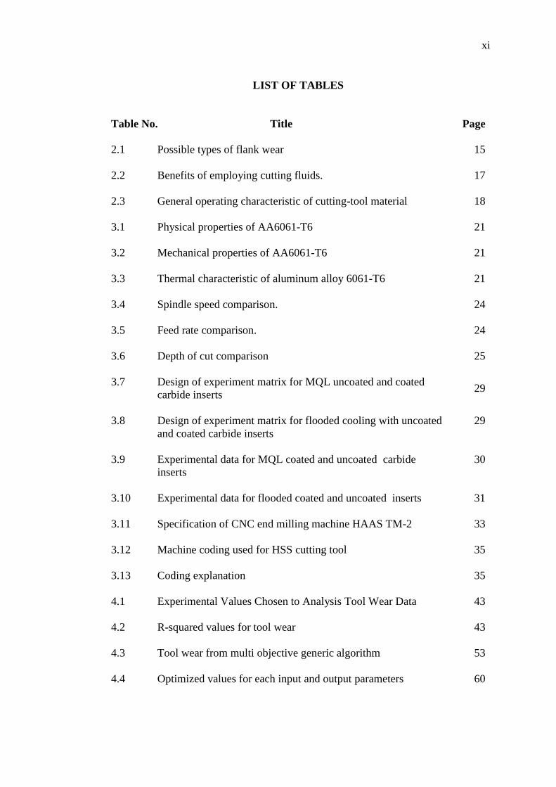
LIST OF TABLES
Table No. Title Page
2.1 Possible types of flank wear 15
2.2 Benefits of employing cutting fluids. 17
2.3 General operating characteristic of cutting-tool material 18
3.1 Physical properties of AA6061-T6 21
3.2 Mechanical properties of AA6061-T6 21
3.3 Thermal characteristic of aluminum alloy 6061-T6 21
3.4 Spindle speed comparison. 24
3.5 Feed rate comparison. 24
3.6 Depth of cut comparison 25
3.7 Design of experiment matrix for MQL uncoated and coated
carbide inserts 29
3.8 Design of experiment matrix for flooded cooling with uncoated
and coated carbide inserts
29
3.9 Experimental data for MQL coated and uncoated carbide
inserts
30
3.10 Experimental data for flooded coated and uncoated inserts 31
3.11 Specification of CNC end milling machine HAAS TM-2 33
3.12 Machine coding used for HSS cutting tool 35
3.13 Coding explanation 35
4.1 Experimental Values Chosen to Analysis Tool Wear Data 43
4.2 R-squared values for tool wear 43
4.3 Tool wear from multi objective generic algorithm 53
4.4 Optimized values for each input and output parameters 60

xii
LIST OF FIGURES
Figure No. Title Page
2.1 CNC vertical type end milling machine 6
2.2 Vertical end milling 7
2.3 Surface finish 11
2.4 Surface roughness parameters relation to other parameters 11
2.5 Flank Wear 13
2.6 Tool wear 14
2.7 Cost comparison of MQL and flooded coolant 16
2.8 Effect of feed on chip formed 19
3.1 Work piece Aluminum Alloy 6061-T6 22
3.2 Insert tighten on tool holder 25
3.3 (a) Coated 1235, (b) coated 2235, and (c) uncoated 4615
carbide insert
26
3.4 Surface roughness profile 27
3.5 Workpiece clamped on machine. 32
3.6 CNC end milling machine HAAS TM-2 32
3.7 Z-depth compensation being set by dial gage 33
3.8 G54 setting with H spindle 34
3.9 Surface roughness measuring device 36
3.10 Optical video measuring system 37
3.11 Tool dimension measurement of HSS tool 37
3.12 UNIST Coolube MQL supply 38
3.13 Nozzle configuration around the HSS tool 38

xiii
4.1 Variation of tool wear on spindle speed for MQL and flooded
conditions
46
4.2 Variation of tool wear against feed rate for MQL and flooded
conditions
47
4.3 Variation of tool wear on depth of cut for MQL and flooded
condition
49
4.4 Variations of tool wear on MQL flow rate for different inserts 50
4.5 Tool wear on different inserts for MQL and flooded conditions
(i) coated carbide 2235; (ii) coated carbide 1235; (iii) uncoated
carbide 4615.
51
4.6 Significance of Input Parameter in Tool Wear on (i) coated
carbide 1235, (ii) coated carbide 2235 and (iii) uncoated
carbide 4615
54
4.7 Tool wear versus spindle speedfor coated CTP 2235, coated
CTP 1235 and uncoated CTW 4615.
56
4.8 Tool wear versus feed rate for coated CTP 2235, coated CTP
1235 and Uncoated CTW 4615.
57
4.9 Tool wear versus depth of cutfor coated CTP 2235, coated CTP
1235 and Uncoated CTW 4615.
58
4.10 Tool wear versus MQL flow ratefor coated CTP 2235, coated
CTP 1235 and Uncoated CTW 4615.
59
xiv
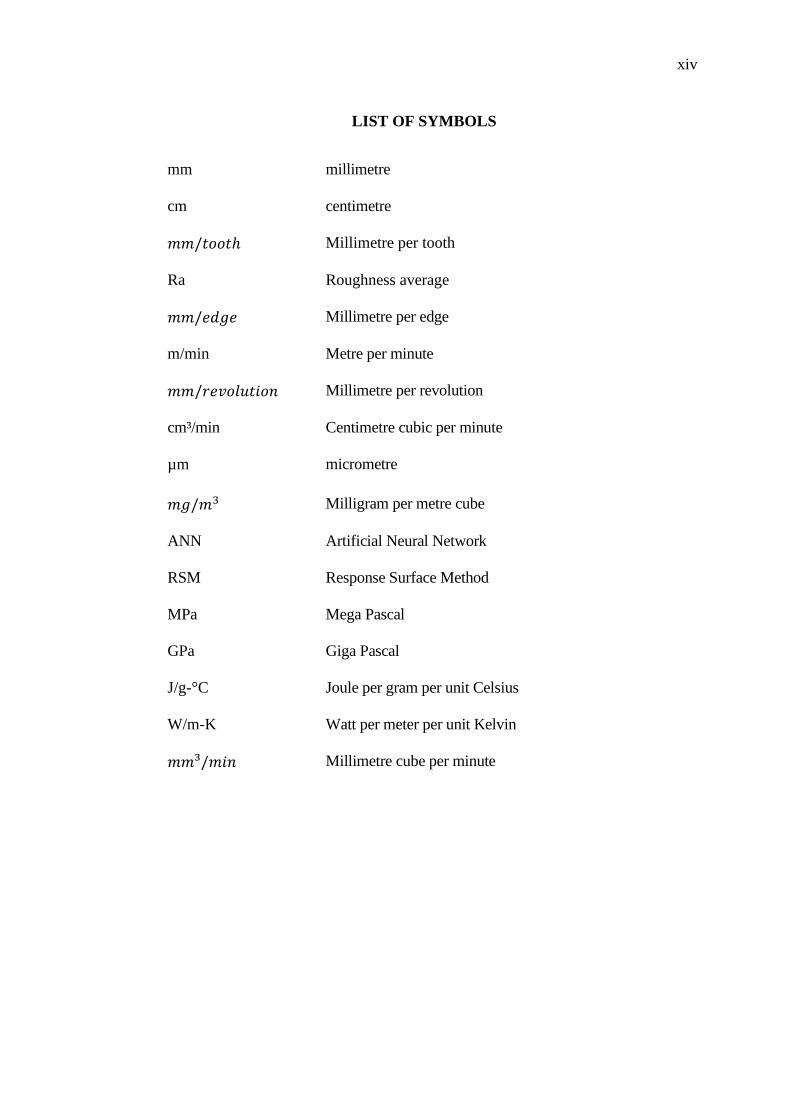
LIST OF SYMBOLS
mm millimetre
cm centimetre
Millimetre per tooth
Ra Roughness average
Millimetre per edge
m/min Metre per minute
Millimetre per revolution
cm³/min Centimetre cubic per minute
µm micrometre
Milligram per metre cube
ANN Artificial Neural Network
RSM Response Surface Method
MPa Mega Pascal
GPa Giga Pascal
J/g-°C Joule per gram per unit Celsius
W/m-K Watt per meter per unit Kelvin
Millimetre cube per minute
xv
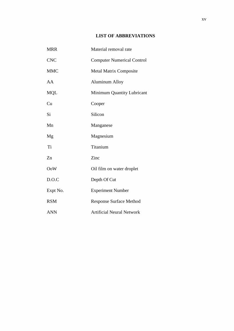
LIST OF ABBREVIATIONS
MRR Material removal rate
CNC Computer Numerical Control
MMC Metal Matrix Composite
AA Aluminum Alloy
MQL Minimum Quantity Lubricant
Cu Cooper
Si Silicon
Mn Manganese
Mg Magnesium
Ti Titanium
Zn Zinc
OoW Oil film on water droplet
D.O.C Depth Of Cut
Expt No. Experiment Number
RSM Response Surface Method
ANN Artificial Neural Network

CHAPTER 1
INTRODUCTION
1.1 INTRODUCTION
Aluminum alloys are trending materials for machining in current world (El-
Gallab and Salad, 1998). This is due to its low density (0.33 times density of steel),
high fatigue, mass reduction (50% less than grey iron), resistance to corrosion and
improved mechanical and chemical properties. According to Frankel and McCreery
(2001), aluminum alloys are well known for aerospace industries especially the 2000
series aluminum alloys with high amount of copper. They also stated that a large
amount of money being spent for the study of performance improvement and also
resistivity towards the corrosion. The use of aluminum base alloy bearings are
famous in industrial application especially in internal combustion engines, which
needs a good friction and wear resistant material (Liu, 1991).The aluminum alloys
are potential to adhere the tool, thus causing built up edge (BUE) and built up layer
(BUL) (Broga et al., 2002). According to Cho and Bes (2006), due to improvement
in metallurgical and heat treatment process, precipitate were used to improve
strength and toughness in alloys, such as Al 2139, which can be applied in military
purpose. The aluminum alloy 6061-T6 is one of the popular materials in fabricating
thermally stable, high strength and light weighted nanostructure material through
large strain deformation (Shankar et al., 2005).
In machining, cutting fluids are important. The large amount of coolant usage
contains harmful chemicals both to health of workers engaged in daily machining
process and also to the environment (Kalita, 2009). These coolants are expensive in
term of recycling and also application. Besides, heavy usage of coolant also does not
promise a good lubrication. On the other hand, according to some research, dry

2
grinding caused an excessive friction force between grinding wheel and work piece
(Shen et al., 2008). This leads to high temperature in grinding contact area and
causes tool wear, poor work piece surface cut and accumulation of chips. Aluminum
alloys are competitively being used in current industries especially in automotive and
aeronautics sector. The unique property of it, which is light and strong, makes it a
good material for production purpose. This study helps to identify the machinability
of aluminum alloy 6061-T6. This research is mainly intended to machine the
aluminum alloy 6061-T6 under minimum quantity lubricant. Besides, the urges to
use MQL in industries are increasing. This is due to the bad effect of flooded coolant
towards the environment and human health. According to Boswell and Islam, (2012),
the challenge of MQL usage is to dissipate the heat from the tool and work piece in
order to ensure the dimensional integrity.
Response parameter such as surface quality is an important parameter
especially when producing parts like airfoil in order to reduce the friction (Fuh and
Wu, 1995). There are several ways to find the optimized parameter values before
machining. Kadirgama et al. (2008) found the optimized value by using response
surface method (RSM) and radian basis function network (RBFN). They also
mentioned that surface roughness is significant as rough surfaces wear much faster
due to the irregularities in the surface which might form nucleation sites for crack
and corrosion.
1.2 PROBLEM STATEMENT
A great challenge is currently being faced which is competitive marketing
place due to manufacturing environment, low costs, aim for high rates of
productivity and also requirement for high quality by the customers. According to
Kadirgama et al. (2011), the important characteristics of tool wear are cracking, flank
wear, catastrophic, notching, chipping, plastic lowering and the cutting edge and so
on. Broga et al. (2002) mentioned that aluminum alloys are potential to adhere the
tool, thus causing built up edge and built up layer. Certain process is very significant
such as finishing process should be in given dimension, surface finish, type of
surface generations, tolerances, and other behaviours (Yahya, 2007). The accuracy of

3
work piece dimension, surface finish, tool wear and tool life towards material
removal rate and cutting tool have increased for enhancing the product performance
in relation to the impact of environment (Ulutan and Ozel, 2011). The machinability
characteristics could be improved if a proper amount of lubricant is applied during
machining (Sreejith, 2008). According to Kalita (2009), MQL in high energy
machining might not be suitable due to the high temperature and thermal spread over
longer time at machining surface. Keeping in mind about this constrains and
problems, this study is conducted by considering all the important parameters such as
spindle speed, feed rate, tool wear, surface roughness, material removal rate and
depth of cut. Besides, a mathematical model are presented to find a combination of
independent variables of CNC end milling process to achieve a good result.
1.3 OBJECTIVES OF STUDY
The objectives of this study are as follows:
1) To investigate the end milling machining characteristics towards the tool wear.
2) To develop a model of process optimization based on the response surface method.
3) To evaluate the progression of tool wear due to the usage of minimum quantity
lubricant compared to the flooded coolant.
1.4 SCOPE OF STUDY
This study is related to machining of aluminum alloy 6061-T6 under different
conditions. The machining type was chosen end milling. The process parameters
including the cutting speed, depth of cut and feed rate are selected for study. Since
this study includes minimum quantity lubrication (MQL), the amount of MQL will
be varied. Three types of tools will be used in this experiment which are coated
carbide CTP 2235, coated carbide CTP 1235 and uncoated carbide CTW 4615 tool.
The cutting is made with flooded condition and MQL condition for the purpose of
comparison. The diameter of tool holder is 10 mm. This experiment was conducted
based on central composite design (CCD) method. After each cut, the tool condition
are brought for tool wear inspection under the optical video measuring system and

4
scanning electron microscope. The chips will be collected after every cut. The
surface roughness will be measured and recorded for further analysis.
1.5 ORGANIZATION OF THESIS
This report was prepared with sufficient information based on theories,
observation, facts, procedures and argument. There are five chapters including
introduction chapter in this study. Chapter 2 presents the literature review of previous
studies includes the end milling, process parameters, response parameters, prediction
modelling. Meanwhile, Chapter 3 discusses the design of experiment, preparation of
experimentation, mathematical modelling techniques and statistical methods. In
Chapter 4, the important findings are presented in this chapter. Chapter 5 concludes
the outcomes of this study and recommendations for future research.

CHAPTER 2
LITERATURE REVIEW
2.1 INTRODUCTION
This chapter provides the review from previous research efforts related to
milling process, CNC milling machine, cutting parameters in milling machine, and
cutting tools. This chapter also involves a review on research studies such as
response surface method which are related to the mathematical modelling.
Substantial literature has been studied on machinability of aluminum alloys which is
covers on surface roughness, tool life, tool wear cutting force and chip formation.
This review has been well elaborated to cover different dimensions about the current
content of the literature, the scope and the direction of current research. This study
has been made in order to help identifying proper parameters involved in this
experiment. The review is fairly detailed so that the present research effort can be
properly tailored to add to the current body of the literature as well as to justify the
scope and direction of present.
2.2 END MILLING
Kalpakjian and Schmid (2006) states that milling includes a high performed
machining operation by using milling cutter in different types of configuration.
Milling cutter is multi-tooth tool that cuts the workpiece and produces a number of
chip in a revolution. End milling is one of the common machining operation due to
its capability of producing different profiles and curved surfaces. Cutter used in end
milling is known as end mill. It is either straight shank for small size or tapered
shank for large cutters and is mounted into the spindle of milling machine. The cutter
6
usually spins on an axis perpendicular to the workpiece surface which is mounted on
the work table. This cutter can be tilted for the purpose of machine tapered or curved
surfaces. End milling is useful in producing variety of surface at any depths such as
curved, stepped and pocketed. End mills usually are made of high speed cutting steel
or from carbide inserts. The typical dimensional tolerances of the end mills used are
in between 0.13 mm to 0.25 mm (Kalpakjian and Schmid, 2006).This type of
machining must be handled with care and there are certain guidelines for a proper
handling of this machine such as stated follows:
a) Standard milling cutters are preferable and costly ones should be avoided.
b) Internal cavities and pockets with sharp edges must be avoided due to the
difficulty of milling them. If possible, corner radius should match the
milling cutter geometry.
c) Clamping of workpieces must be rigid to avoid deflection and unwanted
results in the end of machining. This rule also applies to the tool holders
and other fixtures.
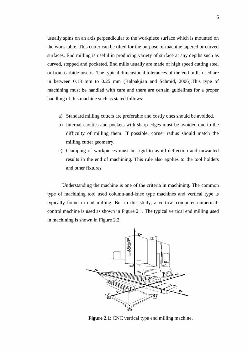
Understanding the machine is one of the criteria in machining. The common
type of machining tool used column-and-knee type machines and vertical type is
typically found in end milling. But in this study, a vertical computer numerical-
control machine is used as shown in Figure 2.1. The typical vertical end milling used
in machining is shown in Figure 2.2.
Figure 2.1: CNC vertical type end milling machine.

7
Figure 2.2: Vertical end milling.
A number of machining types were compared and reviewed that milling
relative cost for machinery and equipment ranges from low to medium (Kalpakjian
and Schmid, 2006). Due to low cost, milling was selected as preferable machining
type. Besides, the number of labour in charge for this machine is less. CNC machine
is widely used to perform milling process because of its small computers with large
memories, low cost programmable controller and microprocessor, and also due to
program editing capabilities. Yazdi and Khorram (2010) mentioned that economy of
machining operation plays a key role in competitiveness in the market. With multi-
tooth cutting tools, it is able to produce complex shapes. On the other hand, Itoigawa
et al. (2006) realised the end milling by using MQL is much more effective than
turning. According to Thangarasu and Sivasubramaniam (2012), optimum
parameters are important in end milling to reduce the machining cost and time to
increase the accuracy and precision.
2.3 PROCESS PARAMETERS
2.3.1 Spindle Speed
There are four important input parameters that decide the outcome of the
machining of aluminium alloy. Spindle speeds are one of the important parameters.
Cutting Tool
Workpiece

8
A general recommended speed was given by Kalpakjian and Schmid (2006) for
aluminium alloy of 300 m/min to 3000 m/min. Wang and Hsu (2004) set up spindle
speed with a range of 1005 m/min to 3519 m/min in order to achieve a good surface
roughness and at the same time to increase the material removal rate on aluminium
alloy 6061-T6. By increasing spindle speed, it will increase the surface roughness
due to chatter problem. The final optimum cutting speed parameter of 1257 m/min
has been chosen to get the best surface finish and material removal rate. According to
Yazdi and Khorram (2010) for a good surface finishing of aluminium alloy 6061-T6,
the spindle speed of 754 m/min to 1508 m/min were used. The optimum value was
1508 m/min for a good surface finish. Rao and Shin (2001) were analysed on high
speed face milling of 7075-T6 aluminium using carbide cutters with cutting speed
range of 518 m/min to 1585 m/min. Surface roughness improved with cutting speed
of 1524 m/min. On the other hand, Fuh and Wu (1995) proposed statistical model for
surface quality prediction in end milling of aluminium alloy. The workpiece used
was 2014 aluminium alloy, with spindle speed between 31.42 m/min to 235.6 m/min.
According to their result, optimum value of cutting speed was 125.66 m/min.
Another experiment carried out by Kadirgama et al. (2008) using aluminium alloy
6061-T6 as the workpiece with cutting speed between 100 m/min to 180 m/min. This
experiment was carried out to find the best surface roughness in end milling of
AA6061-T6 using surface response method and radian basis method. Optimum value
of surface roughness was achieved at 100 m/min. Thangarasu and Sivasubramaniam
(2012), a cutting speed of 3000 m/min to 12000 m/min were selected for a high
speed CNC milling on aluminium alloys. The optimum spindle speed was 3544
m/min. By using aluminium silicon alloy, Boswell and Islam (2012) used end milling
with spindle speed range of 135 m/min to 165 m/min. A number of different types of
experiments were carried out with MQL, dry, MQL with air, air, and flooded. At 150
m/min, a minimum surface roughness result was shown with minimum quantity of
lubrication. Meanwhile, Fuh and Chang (1997) used different types of aluminum
alloy with different hardness. Machining of aluminum alloy 6061-T6 is related to
present study machined with a cutting speed range of 40 to 160 m/min. At 90 m/min,
it shows an error of 7% which is low.

9
2.3.2 Feed Rate
Kalpakjian and Schmid (2006) recommended a value of feed rate between
0.08 mm/tooth to 0.46 mm/tooth. Ginta et al. (2008) showed that tool life gets longer
at lower feed rate. According to Wang and Hsu (2004), the feed rate was chosen as
their experiment range values with 40 m/min to 90 m/min. The optimum feed rate
was 90 m/min to achieve the best surface roughness and material removal rate.
Reduced feed rate causes the material removal rate to reduce. On the other hand,
Yazdi and Khorram (2010) used a range between 0.5 to 2 m/min feed rate values. A
good surface finish obtained at 0.5 m/min. With different types of aluminum alloy
(Fuh and Chang, 1997) used a feed rate of 0.03 mm/edge to 0.12 mm/edge for the
peripheral milling. By using end milling, Arokiadass et al. (2012) set up feed rate
between 0.04 to 0.24 m/min. Maximum feed rate for a minimum tool flank wear was
chosen of 0.044 m/min. On the other hand, Rao and Shin (2001) used a value of 0.2
mm/tooth for feed rate with carbide inserts. Other experiments carried out by Fuh
and Wu (1995), used a feed rate between 0.05 to 0.2 mm/edge and the optimum
result was 0.03 mm/edge. Kadirgama et al. (2008) used feed rate between 0.1
mm/rev to 0.2 mm/rev. For a fine surface the result was 0.2 mm/rev. Thangarasu and
Sivasubramaniam (2012), the range of feed rate on CNC milling of aluminium was
36 m/min to 108 m/min. Feed rate of 85.8 m/min would yield a better material
removal rate. A constant feed rate was used by Boswell and Islam (2012) was 0.4
m/min to make a better decision with different cooling parameters.
2.3.3 Axial Depth of Cut
An axial depth of cut has an important effect on cutting force (Lai, 2000). The
length of engaged flute increases with the axial depth of cut and thus increasing the
cutting force which affects the cutting tools. Wang and Hsu (2004) chosen to use the
axial depth of cut with range of 0.055 mm to 0.085 mm. The optimum depth of cut
was 0.08 mm with better removal rate. Yazdi and Khorram (2010) used depth of cut
ranging from 0.25 mm to 1.0 mm. The optimum value was 1 mm for a good surface
cut. Meanwhile, Arokiadass et al. (2012) chosen a range of depth of cut within 0.5
mm to 2.5 mm and the optimum result was 0.5893 mm. In Rao and Shin (2001), the
10
depth of cut chosen was between 0.76 mm to 2.29 mm. With depth of cut of 2.54
mm, chip thickness obtained was 0.122 mm. Fuh and Wu (1995) used depth of cut
between 1 to 6 mm and the optimum depth of cut was 2.5 mm. Kadirgama et al.
(2008) mentioned the best result was 0.1 mm for a fine surface cut. The range used
was between 0.1 to 0.2 mm. The higher the depth of cut, the better removal rate it
could yield. Fuh and Chang (1997) applied an axial depth of cut with range of 8 mm
to 32 mm for peripheral milling different types of aluminum alloys. According to
Thangarasu and Sivasubramaniam (2012), the depth of cut used was within 0.4 to 1
mm and the optimum result was 0.65 mm. On the other hand, with different types of
cooling parameter, Boswell and Islam (2012) used a constant axial depth of cut
which was 3 mm.
2.4 RESPONSE PARAMETERS
2.4.1 Surface Roughness
Wang and Hsu (2004) experimentally investigated that the best surface
roughness was 0.04878 µm. Optimum result was chosen to get this values. In the
other experiment carried by Yazdi and Khorram (2010), the best surface roughness
obtained was 0.11 µm. From Fuh and Wu (1995), it showed that the minimum
surface roughness was 2.95 µm. They received a better surface roughness at spindle
speed up till 1524 m/min and degrades after that value. An increase in depth of cut
has slightly increased the roughness of aluminum 7075-T6 surface. The surface
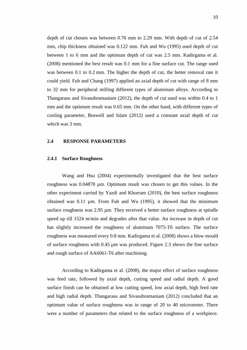
roughness was measured every 0.8 mm. Kadirgama et al. (2008) shows a blow mould
of surface roughness with 0.45 µm was produced. Figure 2.3 shows the fine surface
and rough surface of AA6061-T6 after machining.
According to Kadirgama et al. (2008), the major effect of surface roughness
was feed rate, followed by axial depth, cutting speed and radial depth. A good
surface finish can be obtained at low cutting speed, low axial depth, high feed rate
and high radial depth. Thangarasu and Sivasubramaniam (2012) concluded that an
optimum value of surface roughness was in range of 20 to 40 micrometer. There
were a number of parameters that related to the surface roughness of a workpiece.

11
Figure 2.4 shows the fish bone diagram shows the parameters involved. With 150
m/min, Boswell and Islam (2012) acquired the surface roughness about 0.7
micrometer. This was the minimum result with the usage of minimum quantity
lubrication. The surface roughness was measured parallel to the feed direction
(Sreejith, 2008). At all experiment, it was realized that surface of workpiece could be
improved by applying lubricant.
(a) Fine surface (b) Rough surface
Figure 2.3: Surface finish (Kadirgama et al., 2008).
Figure 2.4: Surface roughness parameters relation to other parameters.
Source: Thangarasu and Sivasubramaniam (2012).
Surface Roughness
Cutting Phenomena
Chip Formation
Machining Parameters
Process Kinematics,
Cooling Fluid , Depth of Cut,
Feed rate, Cutting speed,
tool angle
Cutting Properties
Tool material,
tool shape.
Workpiece Properties
Workpiece length,
workpiece diameter, workpiece hardness

12
2.4.2 Material Removal Rate
Material removal rate is the amount of material removed in forms of chip
during the milling process. Basically, the higher the material removal rate, the better
it is due to faster processing and to save the power of cutting several times. Even
though higher material removal rate is good. The maximum removal rate could cause
the tool to wear easily and also causes higher surface roughness. Therefore, an
optimum result must be chosen which has a lower surface roughness and higher
material removal rate. Wang and Hsu (2004) obtained material removal rate with a
value of 495 mm³/min. Besides, Yazdi and Khorram (2010) acquired a better
material removal rate with a value of 29800 mm³/min. On the other hand,
Thangarasu and Sivasubramaniam (2012) chosen material removal rate ranging from
1500 to 2000 mm-3
as the optimum result. Equation (2.1) is to calculate material
removal rate.
1000
vdwQ
(2.1)
where,
Q = material removal rate.
w = width of cut (mm)
d = depth of cut (mm)
v = feed rate (mm/min)
2.4.3 Tool Wear
Kalpakjian and Schmid (2006) studied the relationship of tool wear, the
surface finish and integrity, dimensional accuracy, temperature rise, force and power.
Tool life needs to be longer for an economical machinability. Tool life basically
relates to the tool wear and the failure. Tool wear generally classified as flank wear,
cutter wear, nose wear, notching, plastic deformation of the tool tip, chipping and
gross fracture. Flank wear occurs at relief of the tool due to contact of the tool along
machined surface and high temperatures between tool and workpieces. Nouari et al.

13
(2003) mentioned that coating in tools helps to reduce the tool wear and thus,
increase tool life. The heat produced during the machining is critical in tool wear and
workpiece surface quality especially in dry machining. Arokiadass et al. (2012),
investigated that the carbide tool flank wear and the minimum flank wear obtained
was 0.1102 mm. The flank wear was measured with Metzer tool maker's microscope.
The workpiece used in this experiment was LM25 aluminium alloy. Boswell and
Islam (2012) applied a criteria whereby a maximum notch wear of 1.0 mm. Tools
were expected to reach its limit with the observation on part surface quality and burr
formation. Arokiadass et al. (2012), investigated at high temperature, the flank wear
increases. They have used flat end uncoated solid carbide tool. Figure 2.5 shows the
flank wear in cutting tool (Arokiadass et al. 2012).
Figure 2.5: Flank wear.
Source: Arokiadass et al. (2012)
Sreejith (2008) carried out the studied that the effect of different types of
coolant environment for tool wear. The adhesion of tool wear increases with increase
in spindle speed. The worst rates of tool wear were recorded for dry machining.
Material adhesion was checked on the tool surface such as flank, rake and clearance
surface. Tool wear can be reduced by using smaller nose radius and by geometrically