experimental investigation of quadrifilar helix antennas ... · 6 the amsat journal may/june 2004...
TRANSCRIPT

6 The AMSAT Journal May/June 2004 www.amsat.org
ANTENNAS
Experimental Investigation of Quadrifilar Helix Antennas for 2400 MHzby Domenico Marini, I8CVS
This article first appeared in the AMSAT-DL Journal. Translated by Reinhard Richter, DJ1KM.Translated for The AMSAT Journal by John J. Bubbers, W1GYD
Figure 1Four sample Quadrifilar Antennas
T he Quadrifilar HelixAntenna as shown inFigure 1 has already been
described in detail and discussedin references [1], [2], [3], [4]. Thatdiscussion will not be repeatedhere. Unfortunately, very little hasbeen written on how to built aQuadrifilar Helix Antenna toradiate with RHCP (Right HandCircular Polarization) or withLHCP (Left Hand CircularPolarization).To test the radiation characteristicsof a Quadrifilar Helix antenna,four prototypes were built for 2400MHz. As can be seen from Figure1, RHCP or LHCP is achieved ifboth loops are wound in thereverse direction of the desiredfield rotation so that LHCP isachieved by winding both loopsright hand and RHCP by windingboth loops left hand, which isexactly the opposite of a W8JKtype helix antenna.Figure 2 contains the designdetails. Half of the small bifilarloop was made of semi-rigidcoaxial cable, UT-047. Silverplated copper wire with a diameterof 1.2 mm was used for the other half of thesmall bifilar loop and for the entire larger,second bifilar loop.In Figure 2 the ends of the loops areconnected to a so-called infinite balunhaving a phase relationship that herereinforces the field in the upward directionto generate endfire radiation. That cancelsthe field toward the SMA connector and feedpoint.In Figure 3 it can be seen how the small andthe large bifilar loops of a RHCP QuadrifilarHelix are wound in the left-hand directionand are connected to the infinite balunhaving a phase relationship that reinforcesthe field in the downward direction togenerate a backfire radiation that reinforcesthe right-hand circular field toward thefeedpoint and creates a null in the upwarddirection of the picture in Figure 3.Because the phase relationship in Figures 2and 3 produces currents that reinforce thefield in one direction and a field cancellationin the opposite direction, then both the aboveRHCP Quadrifilar Helix antennas become
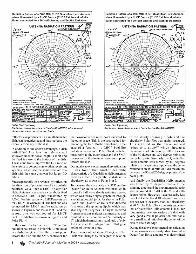
The radiation pattern in Polar Plot1 shows the result of theseexperiments for a RHCPQuadrifilar Helix Antenna withendfire radiation. Polar Plot 2shows the same for a RHCPQuadrifilar Helix Antenna withbackfire radiation.As a further explanation, endfireradiation by definition takes placeopposite to the feed point whilebackfire radiation points towardthe feed point of the antenna. SeePolar Plots 1 to 4.During experimentation withconnections of the loops to theinfinite balun has been found thata connection producing endfireradiation in a RHCP Quadrifilargenerates backfire radiation in aLHCP Quadrifilar as showncomparing Figure 4 to Figure 6.Likewise connections producingendfire radiation in a LHCPQuadrifilar generates backfireradiation in a RHCP Quadrifilaras shown comparing Figure 6 toFigure 5.Another point, which has notbeen discussed in great detail inthe references, is the feeding and
phasing method with help of the infinitebalun. This make it possible the selfmatching of the loop elements to a 50 ohmline as well to feed the loop element in sucha way that either circular endfire radiationor circular backfire radiation can beachieved depending on loop connections tothe infinite balun as schematically illustratedin each of the radiation patterns.The gain of a Quadrifilar Helix Antennaamounts to about 5 dBi and radiationpatterns from Polar Plots 1-4 show that themajor lobe of this type of antenna is verywell suited to be used as a feed to illuminatedishes with a f/D ratio of 0.3. Because theillumination angle for feed at the edge ofthe dish is approximately 159 degrees, thespace attenuation is 4.6 dB and the desiredtaper is 5.4 dB for –10 dB edge illumination.A further advantage of the Quadrifilar Helixantenna compared to a helix or to a patchused as a feed in a parabolic dish is its smallsize because the Quadrifilar Helix Antennais a directional antenna which does not needa reflector, so that the shadow, which a
a directional antenna, which does not needa reflector.Figure 4 shows an enlarged view of theinfinite balun, which is connected for endfireRHCP, as is shown in Polar Plot 1. In Figure4 the RHCP radiation pattern points in thedirection of the viewer. The interconnectionfor RHCP backfire radiation is shown inFigure 5 with the pattern shown in Polar Plot2. In Figure 5 the RHCP radiation takes placein the opposite direction of the viewer andso is toward the feedpoint.Figure 6 shows an enlarged view of theinfinite balun, which is connected for LHCPendfire radiation, which is shown in PolarPlot 3. In Figure 6 the LHCP radiationpattern points at the viewer. In Figure 7 theinterconnection for LHCP backfire radiationis shown in accordance with Polar Plot 4. InFigure 7 the LHCP radiation takes place inthe opposite direction of the viewer and sotoward the feedpoint.

The AMSAT Journal May/June 2004 www.amsat.org 7
Figure 2 (above)Construction of the RCHP-Endfire Type
Figure 3 (above)Construction of the RHCP-Backfire Type
Figure 4 (above)Detail photograph of the RHCP-Endfire
Figure 5 (above)Detail photograph of the RHCP-Backfire
8 The AMSAT Journal May/June 2004 www.amsat.org
Polar Plot 1 (above)Radiation characteristics of the Endfire-RHCP with severaldimensions and construction hints.
Polar Plot 2 (above)Radiation characteristics and hints for the Backfire-RHCP.
reflector can produce with a small diameterdish, can be neglected and thus increase theoverall efficiency of the dish.In addition to the above advantage, a dishwith f/D=0.3 or less has only a smallspillover since its focal length is short andthe feed is close to the bottom of the dish.These conditions improve the G/T ratio ofthe system in comparison to other receivingsystems, which use the same receiver to adish with the same diameter but larger f/Dratios.Since a parabolic dish reverses by reflectionthe direction of polarization of a circularlypolarized wave, then a LHCP QuadrifilarHelix Antenna is needed as a parabolic feedto receive a RHCP signal transmitted byAO40. For this reason two LHCP prototypesfor 2400 MHz where built .The first one wasconnected for LHCP endfire radiation asshown in Figure 6 and Polar Plot 3 and thesecond one was connected for LHCPbackfire radiation as shown in Figure 7 andPolar Plot 4.In the case of a feed with a LHCP endfireradiation pattern as in Polar Plot 3 mountedin a dish, the Quadrifilar Helix must pointtoward the dish and the SMA connector for
the downconverter must point outward tothe outer space. This is the best method formounting the feed. On the other hand, in thecase of a feed with a LHCP backfireradiation pattern as in Polar Plot 4 the helixmust point to the outer space and the SMAconnector for the downconverter must pointtoward the dish.During the above experimental investigationit was found that another desirablecharacteristic of a Quadrifilar Helix Antennaused as a feed in a parabolic dish is itscircularity, as shown in Polar Plot 5.To measure the circularity a RHCP endfireQuadrifilar Helix Antenna was installed infront of a half wave slowly spinning dipole,which was fed by a signal generator througha rotating coaxial joint. As shown in PolarPlot 5, the Quadrifilar Helix was directedfirst toward the spinning dipole, which wasat an angle of 0 degrees. The signal receivedfrom a spectrum analyzer was measured andresulted in the curve marked “circularity at0”, which had a maximum axial ratio of only1 dB between the 0-degree and 180-degreepoints of the polar plots.Then the axis of radiation of the QuadrifilarHelix was changed by 30 degrees in relation
to the slowly spinning dipole and thecircularity Polar Plot was again measured.This resulted in the curve marked“circularity at 30°” which showed amaximum axial ratio of only 1 dB in the caseof the 90-degree and 270-degree-points onthe polar plots. Similarly the QuadrifilarHelix antenna was turned by 60 degreesrelative to the spinning dipole, and the curveresulted in an axial ratio of 3 dB maximumbetween the 90 and 270-degree points of thepolar plots.And finally the Quadrifilar Helix antennawas turned by 90 degrees relative to thespinning dipole and the maximum axial ratiowas measured at 16 dB at the 90 and 270-degree points. However, it decreased by lessthan 1 dB at the 0 and 180-degree points, ascan be seen in the curve marked “circularityat 90°”. The Polar Plot circularity indicatesthat a Quadrifilar Helix antenna is ideal forilluminating the entire surface of a dish withvery good circular polarization and has avery small axial ratio from the center of thedish to about its edge.During the above experimental investigationthe unknown circularity direction of aQuadrifilar Helix antenna was determined

The AMSAT Journal May/June 2004 www.amsat.org 9
Figure 6 (above)Detail photograph of the LHCP-Endfire.
Figure 7 (above)Detail photograph of the LHCP-Backfire.
against a reference patch antenna connectedfor LHCP. A 2400 MHz signal generator asa transmitter drove the patch antenna whilethe Quadrifilar Helix antenna was connectedto a spectrum analyzer as a receiver as seenin Figure 8. If the output from the QuadrifilarHelix antenna remains constant or variesvery little, by less than 1 dB, as the patch isrotated manually through 360°, then theQuadrifilar Helix antenna under test is alsoLHCP. If, however, there are two deep nullsand two peaks observed when rotating thesource patch antenna through 360°, then theQuadrifilar Helix antenna under test hasopposite polarization or RHCP in thisexample.
For those who would like to build andduplicate the Quadrifilar Helix antenna forRHCP or LHCP all of the electricaldimensions and materials to be used as wellas winding directions for the smaller andlarger loops are given in their respectiveillustrations, Figures 2 to 5. For still moredetailed construction designs consult thereferences (3) and (4). For those who wouldlike to know more about the theory and howQuadrifilar Helix Antennas function ingeneral and who want to learn more detailsof the workings of infinite baluns, includinghow the 90-degrees phase shift for circularpolarization as well as the self-matching toa 50-Ohm-feedline takes place, should
definitely study the references (1) and (2).An additional article being planned will dealwith the results obtained with a QuadrifilarHelix Antenna for 2400 MHz used as a feedon dishes with f/D ratio ranging from 0.3 to0.35 hopefully using the RHCP mediumbeacon of AO40 otherwise using the2401.500 MHz LHCP beacon of UO-11.References:[1] “Reflection Transmission Lines andAntennas” by M. Walter Maxwell, W2DU,ARRL, order no. 2995, ISBN 0-87259-299-5.[2] “The ARRL Antenna Book” publishedby The American Radio Relay League(ARRL).[3] “The Satellite Experimenters Handbook”by Martin Davidoff, K2UBC, secondedition, ARRL order No. 3185.[4] “The AMSAT Journal”, March/April1994, “Quadrifilar Antennas for Amateurand 137 MHz Satellites”, by Dave Guimont,WB6LLO.
Figure 8 (left)Measurement bench to determine theunknown circularity direction of aQuadrifilar-Helix antenna against a referencepatch antenna connected for LHCP (see text).
Figures continue on the next page.

10 The AMSAT Journal May/June 2004 www.amsat.org
Polar Plot 3 (above)Radiation characteristics and hints for the Endfire-LHCP.
Polar Plot 4 (above)Radiation characteristics and hints for the Backfire-LHCP.
Polar Plot 5 (left)Antenna axial ratio pattern and measurementbench to determine the circularity of theQuadrifilar-Helix at different squint anglesagainst a spinning half wave dipole.